EP0520908B1 - Linear antenna array - Google Patents
Linear antenna array Download PDFInfo
- Publication number
- EP0520908B1 EP0520908B1 EP19920401820 EP92401820A EP0520908B1 EP 0520908 B1 EP0520908 B1 EP 0520908B1 EP 19920401820 EP19920401820 EP 19920401820 EP 92401820 A EP92401820 A EP 92401820A EP 0520908 B1 EP0520908 B1 EP 0520908B1
- Authority
- EP
- European Patent Office
- Prior art keywords
- antenna
- carrying
- face
- les
- des
- Prior art date
- Legal status (The legal status is an assumption and is not a legal conclusion. Google has not performed a legal analysis and makes no representation as to the accuracy of the status listed.)
- Expired - Lifetime
Links
Images


Classifications
-
- H—ELECTRICITY
- H01—ELECTRIC ELEMENTS
- H01Q—ANTENNAS, i.e. RADIO AERIALS
- H01Q21/00—Antenna arrays or systems
- H01Q21/24—Combinations of antenna units polarised in different directions for transmitting or receiving circularly and elliptically polarised waves or waves linearly polarised in any direction
-
- H—ELECTRICITY
- H01—ELECTRIC ELEMENTS
- H01Q—ANTENNAS, i.e. RADIO AERIALS
- H01Q21/00—Antenna arrays or systems
- H01Q21/0006—Particular feeding systems
- H01Q21/0075—Stripline fed arrays
- H01Q21/0081—Stripline fed arrays using suspended striplines
-
- H—ELECTRICITY
- H01—ELECTRIC ELEMENTS
- H01Q—ANTENNAS, i.e. RADIO AERIALS
- H01Q21/00—Antenna arrays or systems
- H01Q21/06—Arrays of individually energised antenna units similarly polarised and spaced apart
- H01Q21/08—Arrays of individually energised antenna units similarly polarised and spaced apart the units being spaced along or adjacent to a rectilinear path
Definitions
- the invention relates to a linear array antenna with high efficiency.
- Such an antenna is particularly advantageous in the Synthetic Aperture Radar or SAR) used in particular in the space sector.
- network lobes appear in the radiation diagram. Their level is greater than that required for the side lobes, which decreases the antenna gain and creates ambiguities.
- the antenna having a long length, to generate a end lobe in the plane this condition leads to a number of sources prohibitive.
- the document EP 317 414 A1 describes a planar antenna with microstrip suspended, and self-supporting ground planes with thick radiating slots, without positioning pads. This antenna is intended for ground applications of consumer goods, for example satellite TV reception, and its design aims above all at a low production cost.
- the object of the linear array antenna of the invention is to meet all of these specifications.
- the invention proposes, in fact, a linear array antenna composed of a radiating element formed by an alignment of slots annulars excited by at least one distributor element, characterized in that this distributor element is a buried distributor, included in the radiating element, and therefore invisible from the radiating face of said antenna; so as to avoid any stray radiation from said dispatcher.
- Such an antenna is provided to radiate (or receive) simultaneously in two linear polarizations, or for radiate (or receive) simultaneously with two polarizations circular (right and left).
- said antenna includes an integrated radome and a distributor floor.
- said antenna only comprises thin substrates, and therefore of low mass, spaced apart by conductive spacers without mechanical continuity in the plane of the network, so as to avoid differential expansions with substrates.
- said antenna comprises shields, between polarizations of a sub-network and between adjacent sub-networks, radiant elements and distributors so as to avoid any coupling between them.
- the antenna is a broadband antenna using resonant discs etched on the distributor stage, resonating at a frequency close to that of annular slots.
- the antenna is a dual-band antenna using resonant disks engraved on the distributor stage, resonating at a frequency far from that of the annular slots.
- the antenna according to the invention is a linear array antenna composed of an alignment of annular slots excited by at least one buried distribution element, included in the radiating element, and therefore invisible from the radiating face of said antenna; so as to avoid any stray radiation from said distributor.
- Such an antenna is intended to radiate (or receive) simultaneously in two linear polarizations; or to radiate (or receive) simultaneously in two circular polarizations (right and left).
- both half-shells 10 and 15 must be connected to the same potential. This is provided by the first substrate thanks to the metallization of surfaces opposite with the two half-shells and the presence of a large number of metallized holes located on the periphery of the cavities, connecting these two surfaces.
- These three substrates 25, 32 and 37 are spaced apart by the conductive spacers 41, for example of aluminum, which delimit the cavities of the annular slots and the channels of the distributors.
- the assembly can be carried out in a single operation by brazing in the oven after depositing a solder preform at the interfaces between the spacers and the copper substrates, or by tinning the spacers.
- the materials and process used in such realization guarantee very good performances in cost and mass subnets.
- the spacers of small dimensions and without continuity in the network plan allow the use of materials with low coefficient of expansion, compatible for example with a carbon structural panel ensuring high rigidity to the antenna.
- the subnets are much shorter, which allows for a antenna with slightly higher ohmic losses.
- the invention thus makes it possible, in any one of these embodiments to form a space radar antenna with synthesis of aperture comprising a network of 1.33 x 10 m 2 composed of sub-panels of 0.66 x 1 m 2 .
- the elevation scan requiring a step between the subnets of approximately 0.7 ⁇ at 5.3 GHz, no azimuth scanning not being specified, to avoid an additional distributor stage supplying short radiating elements, bipolar sub-networks of the length of the panel (about 1 m) are therefore best suited.
- the invention makes it possible to satisfy all of these specifications with sub-networks of 24 annular slots.
- the antenna therefore performs the functions of radiating element and distributor on one level. Lower and upper spaces are made by aluminum half-shells assembled by screws. The excitation of the two polarizations is achieved by coaxial probes thumbnails placed near the center of the network.
- the radiation diagrams for the horizontal and vertical polarizations are given in FIGS. 4 and 5.
- the normal polarization diagrams 60 and 61 in the azimuth planes are very close to those of an equi-amplitude equi-phase opening like the show the indicators at "*" at ⁇ 3.22 ° which correspond to the first nulls of such an opening.
- the cross polarization diagrams 62 and 63 in the axis are less than 30 dB / max over the entire bandwidth.
Description
L'invention concerne une antenne réseau linéaire à haute efficacité. Une telle antenne est particulièrement avantageuse dans le domaine des radars à synthèse d'ouverture ("Synthetic Aperture Radar" ou SAR) utilisés notamment dans le domaine spatial.The invention relates to a linear array antenna with high efficiency. Such an antenna is particularly advantageous in the Synthetic Aperture Radar or SAR) used in particular in the space sector.
Les antennes utilisées pour de tels radars doivent posséder les propriétés suivantes :
- un gain élevé pour minimiser la puissance émise par le radar ;
- un lobe très fin dans le plan d'azimut (parallèle à l'orbite), de largeur variable pour maintenir une faute constante au sol dans le plan d'élévation (perpendiculaire à la trace) ;
- un balayage très élevé dans le plan d'élévation pour pouvoir accéder très rapidement à n'importe quel site (mission de surveillance) et viser les mêmes sites-test à faible puis forte incidence à 24 heures d'intervalle (observation de la végétation, séparation des effets du sol et du feuillu) ;
- un balayage peu élevé dans le plan d'azimut pour suivre une même zone afin d'augmenter la longueur synthétique de l'antenne et d'obtenir un pouvoir de résolution de quelques mètres parallèlement à l'orbite ;
- deux polarisations linéaires orthogonales (horizontale H et verticale V) pour séparer la rétrodiffusion du sol et celle de la couverture végétale ;
- un niveau de polarisation croisée très faible sur le domaine de balayage de l'antenne ;
- des éléments rayonnants de coût et de masse les plus faibles possibles vu leur grand nombre sur l'antenne.
- a high gain to minimize the power emitted by the radar;
- a very fine lobe in the azimuth plane (parallel to the orbit), of variable width to maintain a constant fault on the ground in the elevation plane (perpendicular to the trace);
- a very high sweep in the elevation plan to be able to access any site very quickly (monitoring mission) and target the same test sites at low then high incidence at 24 hour intervals (observation of vegetation, separation of soil and hardwood effects);
- a low scanning in the azimuth plane to follow the same area in order to increase the synthetic length of the antenna and to obtain a resolving power of a few meters parallel to the orbit;
- two orthogonal linear polarizations (horizontal H and vertical V) to separate the backscattering of the soil and that of the plant cover;
- a very low cross-polarization level on the scanning range of the antenna;
- the lowest possible cost and mass radiating elements given their large number on the antenna.
Ces spécifications ne peuvent être tenues qu'avec une antenne à
rayonnement direct de grande dimension constituée d'un très grand
nombre d'éléments rayomants planaires. En effet, la théorie des lobes
de réseaux montre que, dès que l'angle maximum de dépointage de
l'antenne ( max) dépasse quelques degrés, la distance d entre les
points de commande de phase sur l'antenne doit vérifier la relation :
Avec Bw largeur à la base du lobe principal de l'antenne réseau lorsque celui-ci est pointé selon la normale à l'antenne.With Bw width at the base of the main lobe of the network antenna when it is pointed at normal to the antenna.
Si on ne respecte pas cette condition, des lobes de réseau apparaíssent dans le diagramme de rayonnement. Leur niveau est supérieur à celui demandé pour les lobes secondaires, ce qui diminue le gain de l'antenne et crée des ambiguïtés.If this condition is not met, network lobes appear in the radiation diagram. Their level is greater than that required for the side lobes, which decreases the antenna gain and creates ambiguities.
Une telle condition entraíne les conséquences suivantes :
- Pour le balayage en élévation, le pas doit être proche de λ/2.
- Pour le balayage en azimut, le faible dépointage est compatible avec un pas proche de λ.
- For elevation scanning, the step must be close to λ / 2.
- For the azimuth scan, the weak deflection is compatible with a step close to λ.
Néanmoins, l'antenne ayant une grande longueur, pour générer un lobe fin dans le plan cette condition conduit à un nombre de sources prohibitif.However, the antenna having a long length, to generate a end lobe in the plane this condition leads to a number of sources prohibitive.
Trois solutions sont alors possibles pour réduire le nombre de commandes :
- un réseau raréfié qui rompt la périodicité de la loi d'éclairement et par conséquent détruit les lobes de réseau mais provoque une perte de gain très élevée.
- un réseau à pas non régulier, obtenu en augmentant progressivement la distance entre commandes de phase lorsqu'on s'éloigne du centre de l'antenne. Cette solution, pour ne pas baisser le gain de l'antenne, nécessite de réaliser de nombreux types d'éléments rayonnants différents, ce qui interdit le découpage de l'antenne en sous-panneaux tous identiques et augmente considérablement le coût.
- un réseau formé de sous-réseaux dont la loi d'éclairement dans le plan d'azimut doit être la plus proche possible de celle d'une ouverture uniforme de même longueur. Dans ce cas, pour une visée dans l'axe, les lobes de sous-réseaux de l'antenne sont annulés par les premiers zéros du diagramme du sous-réseau. Cette condition n'est plue vérifiée lors d'un faible balayage en azimut. On détermine alors, pour l'angle de dépointage azimut maximum, la longueur maximale des sous-réseaux pour maintenir les lobes de réseaux à un niveau inférieur à celui des lobes latéraux.
- a rarefied network which breaks the periodicity of the law of illumination and consequently destroys the network lobes but causes a very high loss of gain.
- a non-regular pitch network, obtained by gradually increasing the distance between phase commands when moving away from the center of the antenna. This solution, in order not to lower the gain of the antenna, requires making many different types of radiating elements, which prohibits the cutting of the antenna into all identical sub-panels and considerably increases the cost.
- a network formed by sub-networks whose law of illumination in the azimuth plane must be as close as possible to that of a uniform aperture of the same length. In this case, for an aiming in the axis, the sub-array lobes of the antenna are canceled by the first zeros of the diagram of the sub-array. This condition is no longer verified during a weak azimuth scan. The maximum length of the sub-networks is then determined, for the maximum azimuth depointing angle, to maintain the network lobes at a level lower than that of the lateral lobes.
De même, on constate que, si aucun dépointage en azimut n'est spécifié, un sous-réseau de longueur égale à celle de l'antenne suffit. En pratique, la longueur des sous-réseaux est limitée par la taille des panneaux de l'antenne (1 à 3 mètres) pour être compatible avec l'encombrement sous coiffe du lanceur.Similarly, we note that, if no azimuth deflection is specified, a sub-network of length equal to that of the antenna enough. In practice, the length of the sub-networks is limited by the size of the antenna panels (1 to 3 meters) to be compatible with the space taken up under the launcher's cap.
Actuellement, l'ensemble de ces spécifications ne sont pas tenues pour les éléments rayonnants des radars à synthèse d'ouverture. En effet :
- Les guides à fentes, tels que décrits dans l'article intitulé "the planar array antennas for the european remote sensing satellite ERS-1" de Robert Peterson et Per Ingvarson publié dans "Proceedings of IGARSS 1988", utilisés notamment sur ERS-1 (1991), RADARSAT (1995) et SIR-C (X-SAR), malgré leurs faibles pertes ne permettent pas de réaliser aisément la bipolarisation car il faudrait intercaler deux guides différents rayonnant l'un en polarisation H et l'autre en polarisation V dans le pas d'un réseau très réduit à cause du fort balayage en élévation. De plue, si un balayage en azimut est spécifié, pour limiter le niveau des lobes de réseau, ces guides doivent être coupés en petits tronçons ce qui rend notablement plus complexe leur réalisation et diminue leur intérêt. Cette technologie n'est intéressante que pour les radars possédant une polarisation en bande C ou dans des fréquences supérieures, sans balayage dans le plan d'azimut.
- Les éléments rayonnants imprimés sur nid d'abeilles en bandes L et S, tels que décrits dans l'article intitulé "SEASAT and SIR-A microstrip antennas" de L.R. Murphy paru dans "Proceedings of Workshop on printed antennas technology" (Las Cruces; 1979; pages 18-1 à 18-20), utilisés sur SEASAT (1978), SIR-A (1981), SIR B (1984) et J. ERS (japonais 1992) sont plus légers que les guides et permettent une bipolarisation. Cependant leurs pertes linéiques sont élévées. Ceci limite donc la longueur des sous-réseaux à quelques longueurs d'onde (10 λ au maximum); ces pertes ne permettant pas d'obtenir un éclairement uniforme sur le sous-réseau.
- The slotted guides, as described in the article entitled "the planar array antennas for the european remote sensing satellite ERS-1" by Robert Peterson and Per Ingvarson published in "Proceedings of IGARSS 1988", used in particular on ERS-1 ( 1991), RADARSAT (1995) and SIR-C (X-SAR), despite their low losses, do not allow bipolarization to be easily achieved because two different guides should be inserted, radiating one in H polarization and the other in V polarization in the step of a very reduced network because of the strong sweep in elevation. Furthermore, if an azimuth scan is specified, in order to limit the level of the network lobes, these guides must be cut into small sections which makes their construction considerably more complex and reduces their interest. This technology is only interesting for radars having a polarization in C band or in higher frequencies, without scanning in the azimuth plane.
- The radiating elements printed on honeycomb in L and S bands, as described in the article entitled "SEASAT and SIR-A microstrip antennas" by LR Murphy published in "Proceedings of Workshop on printed antennas technology" (Las Cruces; 1979; pages 18-1 to 18-20), used on SEASAT (1978), SIR-A (1981), SIR B (1984) and J. ERS (Japanese 1992) are lighter than the guides and allow bipolarization. However their linear losses are high. This therefore limits the length of the sub-gratings to a few wavelengths (10 λ maximum); these losses do not make it possible to obtain uniform illumination on the sub-network.
Le document EP 317 414 A1 décrit une antenne plane à microruban suspendu, et plans de masse autoporteurs à fentes rayonnantes épaisses, sans plots de positionnement. Cette antenne est destinée aux applications sol de grande consommation, par exemple la réception de télévision par satellite, et sa conception vise surtout un faible coût de réalisation. The document EP 317 414 A1 describes a planar antenna with microstrip suspended, and self-supporting ground planes with thick radiating slots, without positioning pads. This antenna is intended for ground applications of consumer goods, for example satellite TV reception, and its design aims above all at a low production cost.
L'antenne à réseau linéaire de l'invention a pour objet de satisfaire toutes ces spécifications.The object of the linear array antenna of the invention is to meet all of these specifications.
L'invention propose, en effet, une antenne réseau linéaire composée d'un élément rayonnant formé d'un alignement de fentes annulaires excitées par au moins un élément répartiteur, caractérisée en ce que cet élément répartiteur est un répartiteur enterré, inclue dans l'élément rayonnant, et donc invisible de la face rayonnante de ladite antenne; de manière à éviter tout rayonnement parasite issu dudit répartiteur. Une telle antenne est prévue pour rayonner (ou recevoir) simultanément dans deux polarisations linéaires, ou pour rayonner (ou recevoir) simultanément à deux polarisations circulaires (droite et gauche).The invention proposes, in fact, a linear array antenna composed of a radiating element formed by an alignment of slots annulars excited by at least one distributor element, characterized in that this distributor element is a buried distributor, included in the radiating element, and therefore invisible from the radiating face of said antenna; so as to avoid any stray radiation from said dispatcher. Such an antenna is provided to radiate (or receive) simultaneously in two linear polarizations, or for radiate (or receive) simultaneously with two polarizations circular (right and left).
Dans une réalisation avantageuse utilisant seulement trois niveaux de conducteurs ladite antenne comprend un radome intégré et un étage répartiteur. Avantageusement ladite antenne ne comprend que des substrats de faible épaisseur, et donc de faible masse, espacés par des entretoises conductrices sans continuité mécanique dans le plan du réseau, de manière à éviter les dilatations différentielles avec les substrats. Avantageusement ladite antenne comprend des blindages, entre polarisations d'un sous-réseau et entre sous-réseaux adjacents, des éléments rayonnants et des répartiteurs de manière à éviter tout couplage entre ceux-ci.In an advantageous embodiment using only three conductor levels said antenna includes an integrated radome and a distributor floor. Advantageously, said antenna only comprises thin substrates, and therefore of low mass, spaced apart by conductive spacers without mechanical continuity in the plane of the network, so as to avoid differential expansions with substrates. Advantageously, said antenna comprises shields, between polarizations of a sub-network and between adjacent sub-networks, radiant elements and distributors so as to avoid any coupling between them.
Dans une réalisation particulière de l'invention, l'antenne est une antenne large bande utilisant des disques résonants gravés sur l'étage répartiteur, résonant à une fréquence proche de celle des fentes annulaires.In a particular embodiment of the invention, the antenna is a broadband antenna using resonant discs etched on the distributor stage, resonating at a frequency close to that of annular slots.
Dans une autre réalisation particulière de l'invention; l'antenne est une antenne bi-bande utilisant des disques résonants gravés, sur l'étage répartiteur, résonant à une fréquence éloignée de celle des fentes annulaires.In another particular embodiment of the invention; the antenna is a dual-band antenna using resonant disks engraved on the distributor stage, resonating at a frequency far from that of the annular slots.
Une telle antenne présente de nombreux avantages; Elle permet d'obtenir notamment :
- de faibles pertes,
- un faible niveau de polarisation croisée sur le domaine de balayage,
- une utilisation en bipolarisation : l'antenne réseau selon l'invention pouvant rayonner (ou recevoir) simultanément dans deux polarisations linéaires ou circulaires (droite et gauche);
- un large domaine de balayage en élévation;
- une longueur importante des sous-réseaux;
- un gain élevé;
- des pertes par dépointage similaires dans les deux polarisations.
- low losses,
- a low level of cross polarization on the scanning domain,
- use in bipolarization: the array antenna according to the invention can radiate (or receive) simultaneously in two linear or circular polarizations (right and left);
- a wide sweep range in elevation;
- a significant length of the sub-networks;
- high gain;
- similar depointing losses in the two polarizations.
Les caractéristiques et avantages de l'invention ressortiront d'ailleurs de la description qui va suivre, à titre d'exemple non limitatif, en référence aux figures annexées sur lesquelles :
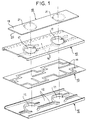
- la figure 1 illustre une vue éclatée d'un tronçon de sous-réseau d'une réalisation de l'antenne selon l'invention;
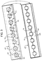
- les figures 2 et 3 illustrent deux vues éclatées de tronçons de sous-réseaux de réalisations de deux variantes de l'antenne selon l'invention;
- les figures 4
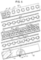
et 5 illustrent respectivement les diagrammes de rayonnement pour les polarisations horizontale et verticale, - les figures 6 et 7 illustrent deux autres variantes de l'antenne selon l'invention.
- Figure 1 illustrates an exploded view of a subarray section of an embodiment of the antenna according to the invention;
- Figures 2 and 3 illustrate two exploded views of sections of sub-arrays of embodiments of two variants of the antenna according to the invention;
- FIGS. 4 and 5 respectively illustrate the radiation diagrams for the horizontal and vertical polarizations,
- Figures 6 and 7 illustrate two other variants of the antenna according to the invention.
L'antenne selon l'invention est une antenne réseau linéaire composée d'un alignement de fentes annulaires excitées par au moins un élément répartiteur enterré, inclus dans l'élément rayonnant, et donc invisible de la face rayonnante de ladite antenne; de manière à éviter tout rayonnement parasite issu dudit répartiteur.The antenna according to the invention is a linear array antenna composed of an alignment of annular slots excited by at least one buried distribution element, included in the radiating element, and therefore invisible from the radiating face of said antenna; so as to avoid any stray radiation from said distributor.
Une telle antenne est prévue pour rayonner (ou recevoir) simultanément dans deux polarisations linéaires; ou pour rayonner (ou recevoir) simultanément dans deux polarisations circulaires (droite et gauche).Such an antenna is intended to radiate (or receive) simultaneously in two linear polarizations; or to radiate (or receive) simultaneously in two circular polarizations (right and left).
La figure 1 illustre un tronçon de sous-réseau d'une telle antenne qui comprend :
- une demi-coquille inférieure 10 en matériau conducteur
(aluminium, fibre de carbone métallisée, ou plastique conducteur par
exemple) dans laquelle est réalisée la cavité 11 des éléments
rayonnants et le
conduit 12 des répartiteurs des deux polarisations; - un premier substrat 13 très mince (
par exemple d'environ 0,1 mm d'épaisseur), possédant un coefficient de dilatation proche de celui du matériau des demi-coquilles, sur lequel sont gravés, en face supérieure, les répartiteursH et V 14; - une demi-coquille supérieure 15 dans laquelle est réalisée le
conduit 16 des répartiteurs des deux polarisations et percée (17) la partie supérieure de la cavité. - un
second substrat 18 identique au premier substrat dont une face supérieure 19 est entièrement décuivrée et l'autre 20 contient les fentes annulaires gravées 21. Ce substrat a pour but de centrer les fentes annulaires au-dessus des cavités et d'assurer une fonction de radôme.
- a lower half-
shell 10 of conductive material (aluminum, metallized carbon fiber, or conductive plastic for example) in which thecavity 11 of the radiating elements and theduct 12 of the distributors of the two polarizations is produced; - a first very thin substrate 13 (for example about 0.1 mm thick), having a coefficient of expansion close to that of the material of the half-shells, on which are etched, on the upper face, the distributors H and
V 14; - an upper half-
shell 15 in which is made theconduit 16 of the distributors of the two polarizations and pierced (17) the upper part of the cavity. - a
second substrate 18 identical to the first substrate, oneupper face 19 of which is completely uncoppered and the other 20 of which contains the etchedannular slots 21. The purpose of this substrate is to center the annular slots above the cavities and to provide a function of radome.
Pour un fonctionnement en "triplaque suspendu" les deux
demi-coquilles 10 et 15 doivent être reliées au même potentiel. Ceci
est assuré par le premier substrat grâce à la métallisation des
surfaces en regard avec les deux demi-coquilles et à la présence d'un
grand nombre de trous métallisés situés sur la périphérie des cavités,
reliant ces deux surfaces.For a "suspended triplate" operation both
half-
Une telle antenne a été réalisée et testée sur des sous-réseaux de 10, 12 et 24 fentes annulaires. L'adéquation entre les spécifications du sous-réseau et ses différents éléments constituants est donné ci-dessous; un tel sous-réseau permet d'obtenir :
- de faibles pertes : le répartiteur en technologie triplaque suspendu sur substrat très mince et de faible tangente de perte avec des parois argentées assure parfaitement cette fonction. L'élément rayonnant est réalisée dans la même technologie.
- un faible niveau de polarisation croisée sur le domaine de balayage : Grâce à l'utilisation d'une technologie triplaque, on évite le rayonnement parasite des lignes et des coudes d'un répartiteur gravé sur le plan rayonnant. On génère un diagramme différence sur la polarisation croisée, grâce à des répartiteurs symétriques par rapport à l'axe du réseau. Ceci permet d'annuler le niveau, déjà faible, de polarisation croisée des fentes annulaires sur tout le domaine de balayage.
- une utilisation en bipolarisation : l'excitation des fentes annulaires est obtenue par deux polarisations linéaires orthogonales ou par deux polarisations circulaires en insérant un coupleur 3 dB à deux sorties déphasées de 90° au centre du sous-réseau rayonnant.
- un large domaine de balayage en élévation : L'utilisation de canaux pour les répartiteurs permet une très grande compacité sur le sous-réseau sans risque de couplage entre polarisations. Le pas dans le plan d'élévation est ainsi considérablement réduit et autorise un large dépointage en élévation.
- une longueur importante des sous-réseaux : Les faibles pertes du répartiteur assurent un éclairement quasi-uniforme en amplitude et en phase du sous-réseau. Sa longueur n'est limitée que par la modification de la loi d'éclairement sur la bande passante du sous-réseau.
- un gain élevé : une adaptation parfaite de la directivité de l'élément rayonnant à celle de la maille du réseau est obtenue grâce à l'utilisation d'une cavité concentrique dont le diamètre permet d'ajuster très précisément cette grandeur. Le domaine de réglage est compris entre 6 dBi pour des fentes quasi-découplées de la cavité dont le périmètre, à la résonance, correspond à la largeur d'onde guidée λg, et 9 dBi pour des fentes résonant à 1,5 λg On couvre ainsi le domaine des mailles carrées de 0,56 à 0,8 λ requises pour de tels réseaux.
- des pertes par dépointage similaires dans les deux polarisations : Les fentes annulaires sur cavité ont un diagramme à quasi-symétrie de révolution. Dans le plan d'élévation, le diagramme est donc invariant avec la polarisation, ce qui garantit les mêmes pertes sur le domaine de balayage.
- des sous-réseaux de faibles coût et masse.
- low losses: the distributor in triplate technology suspended on very thin substrate and low loss tangent with silver walls perfectly performs this function. The radiating element is made in the same technology.
- a low level of crossed polarization on the scanning domain: Thanks to the use of a triplate technology, the parasitic radiation of the lines and the bends of a distributor engraved on the radiating plane is avoided. A difference diagram on the cross polarization is generated, by means of distributors symmetrical with respect to the axis of the network. This cancels the already low level of cross-polarization of the annular slots over the entire scanning range.
- use in bipolarization: the excitation of the annular slits is obtained by two orthogonal linear polarizations or by two circular polarizations by inserting a 3 dB coupler with two outputs phase shifted by 90 ° in the center of the radiating sub-network.
- a wide range of elevation scanning: The use of channels for the distributors allows a very compactness on the sub-network without risk of coupling between polarizations. The pitch in the elevation plane is thus considerably reduced and allows a large depointing in elevation.
- a significant length of the sub-networks: The low losses of the distributor ensure an almost uniform illumination in amplitude and phase of the sub-network. Its length is only limited by the modification of the lighting law on the bandwidth of the subnetwork.
- a high gain: a perfect adaptation of the directivity of the radiating element to that of the mesh of the network is obtained thanks to the use of a concentric cavity whose diameter makes it possible to very precisely adjust this quantity. The adjustment range is between 6 dBi for slots almost decoupled from the cavity whose perimeter, at resonance, corresponds to the guided wavelength λ g , and 9 dBi for slots resonating at 1.5 λ g This covers the range of square meshes of 0.56 to 0.8 λ required for such networks.
- similar depointing losses in the two polarizations: The annular slots on the cavity have a quasi-symmetry of revolution diagram. In the elevation plane, the diagram is therefore invariant with the polarization, which guarantees the same losses on the scanning domain.
- low cost and mass subnets.
Une réalisation particulièrement avantageuse de l'antenne selon l'invention est représentée sur la figure 2. Pour obtenir une faible masse, l'antenne est constituée de trois substrats, d'environ 0,1 mm d'épaisseur, dont les fonctions sont les suivantes :
- un substrat inférieur 25 ayant :
- une face inférieure 26 localement cuivrée (zone 27) autour des
connecteurs d'alimentation
RF 28et 29, collée au panneau structural; une face supérieure 30 entièrement cuivrée (sauf épargne d'alimentation RF), utilisée comme plan de masse;- des trous métallisés 31 reliant les deux surfaces.
- une face inférieure 26 localement cuivrée (zone 27) autour des
connecteurs d'alimentation
- un substrat intermédiaire 32 ayant :
- une face inférieure 33 cuivrée sur les surfaces en regard avec les cloisons formées par des entretoises conductrices 41;
une face supérieure 34 cuivrée sur les surfaces 42 en regard avec les cloisons et sur lescircuits 35 de répartition H et V;- des trous métallisés 44, assurant la liaison électrique entre les deux plans de masse, qui sont disposés à la verticale des cloisons formées par les entretoises 41; (les troue 36 servent pour la soudure des âmes des connecteurs 28 et 29 alimentant les répartiteurs H et V 35);
- un substrat supérieur 37 ayant :
- une face inférieure 38 entièrement cuivrée sauf aux endroits des fentes annulaires 39 et servant de plan de masse au triplaque;
une face supérieure 40 entièrement décuivrée et faisant fonction de radôme.
- a
lower substrate 25 having:- a locally copper-plated lower face 26 (zone 27) around the
RF power connectors - an
upper face 30 entirely coppery (except RF power saving), used as a ground plane; - metallized
holes 31 connecting the two surfaces.
- a locally copper-plated lower face 26 (zone 27) around the
- an
intermediate substrate 32 having:- a copper-plated
lower face 33 on the surfaces facing the partitions formed byconductive spacers 41; - an
upper face 34 coppery on thesurfaces 42 facing the partitions and on the distribution circuits H and V; - metallized
holes 44, ensuring the electrical connection between the two ground planes, which are arranged vertically to the partitions formed by thespacers 41; (theholes 36 are used for soldering the cores of theconnectors
- a copper-plated
- an
upper substrate 37 having:- a
bottom face 38 entirely coppered except at the locations of theannular slots 39 and serving as a ground plane for the triplate; - an
upper face 40 fully uncoppered and acting as a radome.
- a
Ces trois substrats 25, 32 et 37 sont espacés par les
entretoises conductrices 41, par exemple en aluminium, qui délimitent
les cavités des fentes annulaires et les canaux des répartiteurs.These three
L'assemblage peut être réalisé en une seule opération par brasage au four après dépôt d'une préforme de soudure aux interfaces entre les entretoises et les substrats cuivrée, ou par étamage des entretoises. Les matériaux et procédée utilisée dans une telle réalisation garantissent de très bonnes performances en coût et masse des sous-réseaux.The assembly can be carried out in a single operation by brazing in the oven after depositing a solder preform at the interfaces between the spacers and the copper substrates, or by tinning the spacers. The materials and process used in such realization guarantee very good performances in cost and mass subnets.
Au niveau thermique, les entretoises de faibles dimensions et sans continuité dans le plan du réseau permettent d'utiliser des matériaux à coefficient de dilatation faible, compatibles par exemple avec un panneau structural en carbone assurant une grande rigidité à l'antenne.At the thermal level, the spacers of small dimensions and without continuity in the network plan allow the use of materials with low coefficient of expansion, compatible for example with a carbon structural panel ensuring high rigidity to the antenna.
Dans le cas où un dépointage en azimut est spécifié, les sous-réseaux sont beaucoup plus courts, ce qui autorise de prévoir une antenne avec des pertes ohmiques légèrement plus élevées.If an azimuth offset is specified, the subnets are much shorter, which allows for a antenna with slightly higher ohmic losses.
Une variante de l'antenne précèdente est présenté sur la figure 3. L'antenne n'est alors constituée que de deux parties :
- une partie inférieure 45 en matériau conducteur : le plan de
masse est réalisé
par un substrat 43 de faible épaisseur sur lequel sont brasées les entretoises 46; - une partie supérieure 47 en matériau diélectrique; C'est un
substrat qui contient sur la
face supérieure 48 les fentes annulaires 49 et sur laface inférieure 50 les répartiteurs depolarisation 51 et 52 et les excitateurs 53 de fentes. La continuité de la cavité des fentes annulaires dans le substrat est assurée par des trous métallisés 54 qui relient les entretoises au plan de masse des fentes. L'alimentation des répartiteurs se fait par sonde coaxiale à travers deux trous métallisés 55et 56 pour la continuité de masse entre la sonde et le triplaque.
- a
lower part 45 of conductive material: the ground plane is produced by athin substrate 43 on which thespacers 46 are brazed; - an
upper part 47 of dielectric material; It is a substrate which contains on theupper face 48 theannular slots 49 and on thelower face 50 thepolarization distributors slot exciters 53. The continuity of the cavity of the annular slots in the substrate is ensured by metallizedholes 54 which connect the spacers to the ground plane of the slots. The distributors are supplied by coaxial probe through two metallizedholes
Cette variante de l'invention conserve toutes les propriétés de l'antenne représentée sur la figure 1. Seules les pertes ohmiques sont légèrement augmentées au profit d'une simplification de réalisation. Cette augmentation des pertes tout à fait acceptable pour des sous-réseaux courte (< 10 λ ) est due à l'utilisation :
- d'un répartiteur "triplaque suspendu" où l'énergie micro-onde
se propage essentiellement dans le vide car les lignes sont supportées
par une substrat très fin (
environ 0,1 mm); - d'un répartiteur "micro-ruban inversé" où la propagation se fait en grande partie dans le substrat diélectrique d'épaisseur plue forte (environ 1 mm).
- a "suspended triplate" distributor where the microwave energy propagates essentially in a vacuum because the lines are supported by a very thin substrate (about 0.1 mm);
- an "inverted micro-ribbon" distributor where the propagation takes place largely in the dielectric substrate of greater thickness (about 1 mm).
L'invention permet, ainsi, dans l'une quelconque de ces réalisations de former une antenne radar spatial à synthèse d'ouverture comprenant un réseau de 1,33 x 10 m2 composé de sous-panneaux de 0, 66 x 1m2.The invention thus makes it possible, in any one of these embodiments to form a space radar antenna with synthesis of aperture comprising a network of 1.33 x 10 m 2 composed of sub-panels of 0.66 x 1 m 2 .
Le balayage en élévation nécessitant un pas entre les sous-réseaux d'environ 0,7 λ à 5,3 GHz, aucun balayage en azimut n'étant spécifié, pour éviter un étage répartiteur supplémentaire alimentant des éléments rayonnants de faible longueur, des sous-réseaux bipolarisés de la longueur du panneau (environ 1 m) sont donc les mieux adaptée. L'invention permet de satisfaire toutes ces spécifications avec des sous-réseaux de 24 fentes annulaire.The elevation scan requiring a step between the subnets of approximately 0.7 λ at 5.3 GHz, no azimuth scanning not being specified, to avoid an additional distributor stage supplying short radiating elements, bipolar sub-networks of the length of the panel (about 1 m) are therefore best suited. The invention makes it possible to satisfy all of these specifications with sub-networks of 24 annular slots.
L'antenne assure donc les fonctions d'élément rayonnant et de répartiteur sur un seul niveau. Les espaces inférieurs et supérieurs sont réalisés par des demi-coquilles en aluminium assemblées par vis. L'excitation des deux polarisations est réalisés par sondes coaxiales miniatures placées près du centre du réseau.The antenna therefore performs the functions of radiating element and distributor on one level. Lower and upper spaces are made by aluminum half-shells assembled by screws. The excitation of the two polarizations is achieved by coaxial probes thumbnails placed near the center of the network.
Les diagrammes de rayonnement pour les polarisations horizontale
et verticale sont donnés sur les figures 4 et 5. Les diagrammes de
polarisation normale 60 et 61 dans les plans d'azimut sont très
proches de ceux d'une ouverture équi-amplitude équi-phase comme le
montrent les indicateurs à "*" à ± 3,22° qui correspondent aux
premiers nuls d'une telle ouverture. Les diagrammes de polarisation
croisée 62 et 63 dans l'axe sont inférieurs à 30 dB/max sur toute la
bande passante. Pour juger de la qualité de l'antenne, les gains des
deux polarisations doivent être comparés à la directivité théorique D
de la maille du réseau donnée par la formule :
On obtient alors respectivement, en polarisations horizontale et verticale, des pertes de 1,5 dB et de 2,5dB par rapport à cette grandeur. Ces pertes incluent :
- Les erreurs d'excitation des 24 fentes vis-à-vis d'une loi équi-amplitude et équi-phase;
- Les pertes dues à la polarisation croisée;
- Les pertes ohmiques;
- Les pertes de désadaptation en entrée.
- The excitation errors of the 24 slits vis-à-vis an equi-amplitude and equi-phase law;
- Losses due to cross polarization;
- Ohmic losses;
- Input mismatch losses.
Ces résultats permettent de juger de l'intérêt de l'invention pour la réalisation de sous-réseaux linéaires d'antennes.These results make it possible to judge the interest of the invention. for the realization of linear sub-arrays of antennas.
L'invention permet d'obtenir une antenne à double résonateur, comme représenté sur les figures 6 et 7 : Afin d'augmenter la bande passante, ou de faire fonctionner l'antenne à deux fréquences espacées, il est possible de placer en bout des lignes-répartiteurs, telles que représentées sur les figures 2 et 3, dans le même plan que celles-ci, des disques 65 dont le diamètre est ajusté de façon à ce qu'ils résonnent à une fréquence F2 différente de la fréquence de résonance F1 de la fente annulaire située au-dessus.
- Si F2 est proche de F1, on peut ainsi faire fonctionner l'antenne sur une large bande.
- Si F2 est éloignée de F1, on obtient une antenne bi-bande; chacun des deux répartiteurs étant adapté à une bande particulière et excitant une des deux fentes annulaires.
- If F2 is close to F1, it is thus possible to operate the antenna over a wide band.
- If F2 is far from F1, we obtain a dual-band antenna; each of the two distributors being adapted to a particular strip and exciting one of the two annular slots.
Une telle réalisation est compatible avec les deux variantes de
l'invention représentées précédement: Dans la variante triplaque
suspendu les fentes annulaires supplémentaires sont gravées soit sur
la face supérieure soit sur la face inférieure du substrat supérieur.
Sur les figures 6 et 7 les variantes prises en compte sont
respectivement celles illustrées aux figures 2 et 3; le substrat
supérieur 37′ représenté à la figure 6 étant muni, sur sa face
supérieure 67, de fentes 69; des trous métallisés 66 étant prévus pour
permettre la liaison masse fente-masse triplaque.Such an embodiment is compatible with the two variants of
the invention represented previously: In the three-plate variant
suspended the additional annular slots are engraved either on
the upper face is on the lower face of the upper substrate.
In FIGS. 6 and 7, the variants taken into account are
respectively those illustrated in Figures 2 and 3; the substrate
upper 37 ′ shown in Figure 6 being provided on its face
upper 67,
Claims (7)
- A linear antenna array composed of a row of annular windows (21, 39, 49) carried on a substrate (18, 37, 47) co-operating with cavities (11) and window excitation elements (53) provided to cause the antenna to radiate simultaneously with two polarizations, the cavities (11) being defined by spacers (41) without mechanical continuity in the plane of the array, which spacers separate a ground plane (30, 43) and a printed circuit sheet (13, 32, 47) carrying the excitation elements (53) and buried-type feeder circuits (14, 35, 51, 52) for both polarizations, the antenna array being characterized in that the face of the printed circuit sheet carrying the excitation elements is invisible from the radiating face of the antenna, and in that the separator spacers (41) also define channels (16) for the feeder circuits avoiding coupling between polarizations.
- The antenna according to claim 1, in which said substrate (47) carrying said annular windows (49) is also said printed circuit sheet (47) carrying the excitation elements (53).
- The antenna according to claim 1, in which said substrate (18, 37) carrying said annular windows (21, 39) is different from said printed circuit sheet (13, 32) carrying the excitation elements (53).
- The antenna according to claim 1, in which the printed circuit sheet (13, 32) carrying the excitation elements of the windows and the feeder circuits is enclosed between two half shells (10, 15) of conductive material.
- The antenna according to claim 4, in which each half shell is constituted by a substrate (25, 37) having a face on which the spacers (41) are fixed.
- The antenna according to claim 1, in which the printed circuit sheet (47) has a face (48) carrying the annular windows (49) and an opposite face (50) carrying the window excitation elements (53) and the buried feeder circuits (51, 52), said opposite face (50) being placed on a shell (45) constituted by a substrate (43) on which the spacers (46) are soldered.
- The antenna according to any preceding claim, in which resonant disks (65) are etched on the face of the printed circuit sheet carrying the window excitation elements and the feeder circuits.
Applications Claiming Priority (2)
| Application Number | Priority Date | Filing Date | Title |
|---|---|---|---|
| FR9108080 | 1991-06-28 | ||
| FR9108080A FR2678438B1 (en) | 1991-06-28 | 1991-06-28 | LINEAR NETWORK ANTENNA. |
Publications (2)
| Publication Number | Publication Date |
|---|---|
| EP0520908A1 EP0520908A1 (en) | 1992-12-30 |
| EP0520908B1 true EP0520908B1 (en) | 2000-03-01 |
Family
ID=9414474
Family Applications (1)
| Application Number | Title | Priority Date | Filing Date |
|---|---|---|---|
| EP19920401820 Expired - Lifetime EP0520908B1 (en) | 1991-06-28 | 1992-06-26 | Linear antenna array |
Country Status (6)
| Country | Link |
|---|---|
| EP (1) | EP0520908B1 (en) |
| JP (1) | JPH06500909A (en) |
| CA (1) | CA2090323A1 (en) |
| DE (1) | DE69230709T2 (en) |
| FR (1) | FR2678438B1 (en) |
| WO (1) | WO1993000723A1 (en) |
Cited By (2)
| Publication number | Priority date | Publication date | Assignee | Title |
|---|---|---|---|---|
| US6930651B2 (en) | 2003-04-11 | 2005-08-16 | Kathrein-Werke Kg | Reflector for a mobile radio antenna |
| US7023398B2 (en) | 2003-04-11 | 2006-04-04 | Kathrein-Werke Kg | Reflector for a mobile radio antenna |
Families Citing this family (6)
| Publication number | Priority date | Publication date | Assignee | Title |
|---|---|---|---|---|
| FR2703516A1 (en) * | 1993-04-02 | 1994-10-07 | Europ Agence Spatiale | Travelling-wave antenna |
| SE9603565D0 (en) * | 1996-05-13 | 1996-09-30 | Allgon Ab | Flat antenna |
| DE19712510A1 (en) | 1997-03-25 | 1999-01-07 | Pates Tech Patentverwertung | Two-layer broadband planar source |
| SE511064C2 (en) * | 1997-12-12 | 1999-07-26 | Allgon Ab | dual band antenna |
| US6054953A (en) * | 1998-12-10 | 2000-04-25 | Allgon Ab | Dual band antenna |
| US10446928B2 (en) | 2017-06-09 | 2019-10-15 | Mitsubishi Electric Corporation | Phased array antenna |
Family Cites Families (2)
| Publication number | Priority date | Publication date | Assignee | Title |
|---|---|---|---|---|
| ES2072266T3 (en) * | 1987-11-13 | 1995-07-16 | Emmanuel Rammos | FLAT ANTENNA WITH SUSPENDED MICROTAPE AND SELF-SUPPORTING MASS FLATS OF THICK RADIANT SLOTS WITH NO POSITIONING PLOTS. |
| US4929959A (en) * | 1988-03-08 | 1990-05-29 | Communications Satellite Corporation | Dual-polarized printed circuit antenna having its elements capacitively coupled to feedlines |
-
1990
- 1990-06-23 JP JP50136093A patent/JPH06500909A/en active Pending
-
1991
- 1991-06-28 FR FR9108080A patent/FR2678438B1/en not_active Expired - Lifetime
-
1992
- 1992-06-23 WO PCT/FR1992/000570 patent/WO1993000723A1/en active Application Filing
- 1992-06-23 CA CA002090323A patent/CA2090323A1/en not_active Abandoned
- 1992-06-26 EP EP19920401820 patent/EP0520908B1/en not_active Expired - Lifetime
- 1992-06-26 DE DE1992630709 patent/DE69230709T2/en not_active Expired - Fee Related
Cited By (2)
| Publication number | Priority date | Publication date | Assignee | Title |
|---|---|---|---|---|
| US6930651B2 (en) | 2003-04-11 | 2005-08-16 | Kathrein-Werke Kg | Reflector for a mobile radio antenna |
| US7023398B2 (en) | 2003-04-11 | 2006-04-04 | Kathrein-Werke Kg | Reflector for a mobile radio antenna |
Also Published As
| Publication number | Publication date |
|---|---|
| FR2678438A1 (en) | 1992-12-31 |
| CA2090323A1 (en) | 1992-12-29 |
| DE69230709T2 (en) | 2000-09-28 |
| JPH06500909A (en) | 1994-01-27 |
| FR2678438B1 (en) | 1993-09-03 |
| WO1993000723A1 (en) | 1993-01-07 |
| EP0520908A1 (en) | 1992-12-30 |
| DE69230709D1 (en) | 2000-04-06 |
Similar Documents
| Publication | Publication Date | Title |
|---|---|---|
| EP0108463B1 (en) | Radiating element for cross-polarized microwave signals and planar antenna consisting of an array of such elements | |
| EP0205212B1 (en) | Modular microwave antenna units and antenna composed of such units | |
| EP2532050B1 (en) | On-board directional flat-plate antenna, vehicle comprising such an antenna, and satellite telecommunication system comprising such a vehicle | |
| EP0012055B1 (en) | Microstrip monopulse primary feed and antenna using same | |
| FR2652453A1 (en) | COAXIAL ANTENNA HAVING A PROGRESSIVE WAVE POWER TYPE. | |
| EP0205393A1 (en) | Omnidirectional cylindrical antenna | |
| EP2710676B1 (en) | Radiating element for an active array antenna consisting of elementary tiles | |
| EP1073143A1 (en) | Dual polarisation printed antenna and corresponding array | |
| EP2194602A1 (en) | Antenna with shared sources and design process for a multi-beam antenna with shared sources | |
| EP2869400A1 (en) | Bi-polarisation compact power distributor, network of a plurality of distributors, compact radiating element and planar antenna having such a distributor | |
| EP3011639A1 (en) | Source for parabolic antenna | |
| EP0520908B1 (en) | Linear antenna array | |
| FR3105884A1 (en) | Circular polarization dual band Ka satellite antenna horn | |
| CA2035111A1 (en) | Slotted waveguide antenna, particularly for space radars | |
| EP3175509B1 (en) | Log-periodic antenna with wide frequency band | |
| EP4046241B1 (en) | Antenna array | |
| EP0477102B1 (en) | Directional network with adjacent radiator elements for radio communication system and unit with such a directional network | |
| FR2552273A1 (en) | Omnidirectional microwave antenna | |
| EP3900113B1 (en) | Elementary microstrip antenna and array antenna | |
| FR2724491A1 (en) | MINIATURIZED, DOUBLE-POLARIZED, VERY WIDE BAND PLATED ANTENNA | |
| CA2808511A1 (en) | Flat antenna for a terminal operating in dual circular polarisation, airborne terminal and satellite telecommunication system featuring at least one antenna | |
| EP0831550B1 (en) | Versatile array antenna | |
| EP3155690A1 (en) | Flat antenna for satellite communication | |
| EP2889955B1 (en) | Compact antenna structure for satellite telecommunication | |
| FR3022404A1 (en) | SATELLITE TELECOMMUNICATION FLAT ANTENNA |
Legal Events
| Date | Code | Title | Description |
|---|---|---|---|
| PUAI | Public reference made under article 153(3) epc to a published international application that has entered the european phase |
Free format text: ORIGINAL CODE: 0009012 |
|
| AK | Designated contracting states |
Kind code of ref document: A1 Designated state(s): DE FR GB IT SE |
|
| 17P | Request for examination filed |
Effective date: 19930628 |
|
| 17Q | First examination report despatched |
Effective date: 19950602 |
|
| RAP1 | Party data changed (applicant data changed or rights of an application transferred) |
Owner name: ALCATEL SPACE INDUSTRIES |
|
| GRAG | Despatch of communication of intention to grant |
Free format text: ORIGINAL CODE: EPIDOS AGRA |
|
| GRAG | Despatch of communication of intention to grant |
Free format text: ORIGINAL CODE: EPIDOS AGRA |
|
| GRAH | Despatch of communication of intention to grant a patent |
Free format text: ORIGINAL CODE: EPIDOS IGRA |
|
| GRAH | Despatch of communication of intention to grant a patent |
Free format text: ORIGINAL CODE: EPIDOS IGRA |
|
| RAP1 | Party data changed (applicant data changed or rights of an application transferred) |
Owner name: ALCATEL |
|
| GRAA | (expected) grant |
Free format text: ORIGINAL CODE: 0009210 |
|
| AK | Designated contracting states |
Kind code of ref document: B1 Designated state(s): DE FR GB IT SE |
|
| REF | Corresponds to: |
Ref document number: 69230709 Country of ref document: DE Date of ref document: 20000406 |
|
| GBT | Gb: translation of ep patent filed (gb section 77(6)(a)/1977) |
Effective date: 20000329 |
|
| ITF | It: translation for a ep patent filed |
Owner name: JACOBACCI & PERANI S.P.A. |
|
| EN | Fr: translation not filed | ||
| EN4 | Fr: notification of non filing translation in an earlier bopi is erroneous | ||
| PLBE | No opposition filed within time limit |
Free format text: ORIGINAL CODE: 0009261 |
|
| STAA | Information on the status of an ep patent application or granted ep patent |
Free format text: STATUS: NO OPPOSITION FILED WITHIN TIME LIMIT |
|
| 26N | No opposition filed | ||
| REG | Reference to a national code |
Ref country code: GB Ref legal event code: IF02 |
|
| REG | Reference to a national code |
Ref country code: FR Ref legal event code: CD |
|
| PGFP | Annual fee paid to national office [announced via postgrant information from national office to epo] |
Ref country code: SE Payment date: 20090605 Year of fee payment: 18 Ref country code: IT Payment date: 20090619 Year of fee payment: 18 |
|
| PGFP | Annual fee paid to national office [announced via postgrant information from national office to epo] |
Ref country code: GB Payment date: 20090624 Year of fee payment: 18 Ref country code: DE Payment date: 20090619 Year of fee payment: 18 |
|
| EUG | Se: european patent has lapsed | ||
| GBPC | Gb: european patent ceased through non-payment of renewal fee |
Effective date: 20100626 |
|
| REG | Reference to a national code |
Ref country code: FR Ref legal event code: ST Effective date: 20110228 |
|
| PG25 | Lapsed in a contracting state [announced via postgrant information from national office to epo] |
Ref country code: IT Free format text: LAPSE BECAUSE OF NON-PAYMENT OF DUE FEES Effective date: 20100626 |
|
| PG25 | Lapsed in a contracting state [announced via postgrant information from national office to epo] |
Ref country code: DE Free format text: LAPSE BECAUSE OF NON-PAYMENT OF DUE FEES Effective date: 20110101 |
|
| PG25 | Lapsed in a contracting state [announced via postgrant information from national office to epo] |
Ref country code: FR Free format text: LAPSE BECAUSE OF NON-PAYMENT OF DUE FEES Effective date: 20100630 |
|
| PG25 | Lapsed in a contracting state [announced via postgrant information from national office to epo] |
Ref country code: GB Free format text: LAPSE BECAUSE OF NON-PAYMENT OF DUE FEES Effective date: 20100626 |
|
| PG25 | Lapsed in a contracting state [announced via postgrant information from national office to epo] |
Ref country code: SE Free format text: LAPSE BECAUSE OF NON-PAYMENT OF DUE FEES Effective date: 20100627 |
|
| PGFP | Annual fee paid to national office [announced via postgrant information from national office to epo] |
Ref country code: FR Payment date: 20090611 Year of fee payment: 18 |