EP0520844A1 - Electrovalve for anti-lock system - Google Patents
Electrovalve for anti-lock system Download PDFInfo
- Publication number
- EP0520844A1 EP0520844A1 EP19920401427 EP92401427A EP0520844A1 EP 0520844 A1 EP0520844 A1 EP 0520844A1 EP 19920401427 EP19920401427 EP 19920401427 EP 92401427 A EP92401427 A EP 92401427A EP 0520844 A1 EP0520844 A1 EP 0520844A1
- Authority
- EP
- European Patent Office
- Prior art keywords
- pressure
- solenoid valve
- constant
- drawer
- piston means
- Prior art date
- Legal status (The legal status is an assumption and is not a legal conclusion. Google has not performed a legal analysis and makes no representation as to the accuracy of the status listed.)
- Granted
Links
Images

Classifications
-
- B—PERFORMING OPERATIONS; TRANSPORTING
- B60—VEHICLES IN GENERAL
- B60T—VEHICLE BRAKE CONTROL SYSTEMS OR PARTS THEREOF; BRAKE CONTROL SYSTEMS OR PARTS THEREOF, IN GENERAL; ARRANGEMENT OF BRAKING ELEMENTS ON VEHICLES IN GENERAL; PORTABLE DEVICES FOR PREVENTING UNWANTED MOVEMENT OF VEHICLES; VEHICLE MODIFICATIONS TO FACILITATE COOLING OF BRAKES
- B60T8/00—Arrangements for adjusting wheel-braking force to meet varying vehicular or ground-surface conditions, e.g. limiting or varying distribution of braking force
- B60T8/32—Arrangements for adjusting wheel-braking force to meet varying vehicular or ground-surface conditions, e.g. limiting or varying distribution of braking force responsive to a speed condition, e.g. acceleration or deceleration
- B60T8/34—Arrangements for adjusting wheel-braking force to meet varying vehicular or ground-surface conditions, e.g. limiting or varying distribution of braking force responsive to a speed condition, e.g. acceleration or deceleration having a fluid pressure regulator responsive to a speed condition
- B60T8/36—Arrangements for adjusting wheel-braking force to meet varying vehicular or ground-surface conditions, e.g. limiting or varying distribution of braking force responsive to a speed condition, e.g. acceleration or deceleration having a fluid pressure regulator responsive to a speed condition including a pilot valve responding to an electromagnetic force
- B60T8/3615—Electromagnetic valves specially adapted for anti-lock brake and traction control systems
-
- B—PERFORMING OPERATIONS; TRANSPORTING
- B60—VEHICLES IN GENERAL
- B60T—VEHICLE BRAKE CONTROL SYSTEMS OR PARTS THEREOF; BRAKE CONTROL SYSTEMS OR PARTS THEREOF, IN GENERAL; ARRANGEMENT OF BRAKING ELEMENTS ON VEHICLES IN GENERAL; PORTABLE DEVICES FOR PREVENTING UNWANTED MOVEMENT OF VEHICLES; VEHICLE MODIFICATIONS TO FACILITATE COOLING OF BRAKES
- B60T15/00—Construction arrangement, or operation of valves incorporated in power brake systems and not covered by groups B60T11/00 or B60T13/00
- B60T15/02—Application and release valves
- B60T15/025—Electrically controlled valves
- B60T15/028—Electrically controlled valves in hydraulic systems
-
- Y—GENERAL TAGGING OF NEW TECHNOLOGICAL DEVELOPMENTS; GENERAL TAGGING OF CROSS-SECTIONAL TECHNOLOGIES SPANNING OVER SEVERAL SECTIONS OF THE IPC; TECHNICAL SUBJECTS COVERED BY FORMER USPC CROSS-REFERENCE ART COLLECTIONS [XRACs] AND DIGESTS
- Y10—TECHNICAL SUBJECTS COVERED BY FORMER USPC
- Y10T—TECHNICAL SUBJECTS COVERED BY FORMER US CLASSIFICATION
- Y10T137/00—Fluid handling
- Y10T137/8593—Systems
- Y10T137/87169—Supply and exhaust
- Y10T137/87217—Motor
Definitions
- the present invention relates to a solenoid valve, more particularly intended to be inserted in a hydraulic braking circuit for a motor vehicle, between a master cylinder and the brake motors in an anti-lock braking system.
- Hydraulic braking circuits with anti-lock braking device are known and typically comprise between the source of pressurized brake fluid such as an electric pump or a so-called “full power" master cylinder and the brake motors, controlled solenoid valves by a computer, allowing the pressure in the brake motors to be lowered when the computer detects a wheel lock, and a temperate rise in pressure in the brake motors when the computer detects too high a speed of rotation of the wheels.
- the solenoid valves used in these anti-lock braking devices are generally two-position and all-or-nothing solenoid valves and generate great energy consumption on the part of the electropump due to the succession of phases. intake / detent during operation of the anti-lock device. It has also been proposed to use proportional solenoid valves, but when it is desired to minimize the hydraulic leaks in order to reduce the energy consumption of the electric pump, a phenomenon of hysteresis appears in the curve representing the hydraulic pressure in the motors. brake as a function of the actuation force of the solenoid valve, and therefore of the electric current flowing therein, this hysteresis disturbing the management of the pressure in the brake motor by the computer associated with the anti-lock device.
- the present invention therefore aims to provide a solenoid valve for an anti-lock device for the wheels whose energy consumption is as low as possible, and which is simple and reliable, and which allows precise control of the pressure in the brake motors.
- an electrovalve in particular intended to be inserted in a hydraulic braking circuit between at least one source of pressurized brake fluid and at least one pressure receiver in an anti-lock wheel system, comprising in a body a piston means movable between a rest position where it allows communication between the source of pressurized fluid and the pressure receptor and a working position where it allows communication between the pressure receptor and a low-pressure fluid reservoir, characterized in that the piston means is constantly urged towards its rest position by a constant force.
- this constant force is obtained by the application of a constant pressure on a constant surface, in particular of the piston means.
- the constant surface is formed on a drawer constituting the piston means, on a section of a span of this drawer or on the difference of the sections of two spans of the drawer.
- the solenoid valve of the invention may include a pressure limiter capable of supplying the constant pressure from the source pressure, this limiter itself comprising a second slide movable under the effect of the source pressure at against a force exerted by a return spring, this spring being calibrated to a value such that this second drawer, thanks to its displacement, escapes the effect of the source pressure as soon as it exceeds said pressure constant.
- the constant pressure is fixed at a relatively low value, for example between 5 and 10 bars.
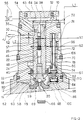
- the solenoid valve shown in Figure 1 consists of a body 10 of generally cylindrical shape, one of the ends 12 of which is provided with a bore 14 for fixing, for example by screwing, the base 16 of an electromagnet 18 (not shown) actuating, under the control of a computer, (not shown) a pusher 20.
- the drawer 24 mainly comprises two bearing surfaces 26 and 28 on either side of a groove defining an annular volume 30.
- a blind bore 32 is formed axially in the drawer 24 and opens into a radial bore 34 formed in the drawer 24 at the level of the bearing surface 28.
- Another radial bore 36 is formed in the slide 24 at the level of the annular groove 30.
- the drawer 24 is returned to its rest position by a return spring 38, taking support on the one hand on a shoulder 40 formed in the body 10 between the bores 22 and 14, and on the other hand on a cup 42 taking it -same support on a stop washer 44 integral with the drawer 24.
- the rest position of the drawer 24 is defined by a pin 46 inserted in the body 10 and cooperating with an oblong slot 48 formed radially in the drawer 24.
- the annular groove 30 of the drawer 24 allows communication between a passage 50 formed in the body 10 and connected to a source of pressurized fluid 52 such as a master cylinder and a passage 54 also formed in the body 10 and connected to a pressure receiver 56 such as a brake motor.
- a closure element 57 in the blind bore 32 confines the pressurized fluid in this bore, the bore 34 being closed by the tight cooperation of the bearing 28 with the wall of the bore 22 of the body 10.
- the solenoid valve therefore allows conventional operation of the braking circuit of the vehicle thus equipped, for braking not requiring the intervention of the anti-lock device of the wheels.
- the computer When the computer detects the impending locking of a wheel, it controls the excitation of the electromagnet 18.
- the pusher 20 then comes into abutment against a ball 58 secured to a guide 60 sliding in the bore 32 of the drawer 24, and biased towards the pusher 20 by a return spring 62 disposed between a shoulder of the guide 60 and the stop washer 44.
- the ball 58 constitutes the movable element of a ball valve which cooperates with a valve seat 59 formed on the base 16 of the electromagnet 18 coaxially with the pusher 20.
- the valve 58-59 is thus closed at rest, that is to say outside of the anti-lock phases, to seal the electromagnet internal circuits of the solenoid valve which communicate with the braking circuit.
- the pusher 20 comes first to urge the ball 58 and the guide 60 against the spring 62 until the guide 60 abuts against the slide 24, then the latter is also biased (upwards in FIG. 1) against the spring 38.
- the bearing surface 26 of the drawer 24 firstly closes the passage 50, thus preventing the supply of pressurized fluid to the receiver 56, then the bearing 28 of the drawer 24 is displaced enough so that the bore 34 is uncovered and opens into a chamber 64 formed at the end of the body 10 opposite that which receives the electromagnet 18, and closed by a plug 65.
- the chamber 64 is connected by a bore 67 made in the body 10 to the annular space 68 around the ball 58 and the guide 60, and to the annular space 69 around the pusher 20 when it lifts the ball 58 from its seat 59 when the electromagnet is energized.
- the annular space 69 is itself in communication with a reservoir of fluid under low pressure 66.
- the pressure receiver 56 therefore communicates, when the electromagnet 18 is energized, with the low-pressure reservoir 66, via the passage 54, the annular groove 30, the radial bore 36, the axial bore 32, the radial bore 34, the chamber 64, the bore 67, and the annular spaces 68 and 69, the axial bore 32 being moreover closed by the element 57 as seen above.
- the pressure in the pressure receiver 56 can then drop, until the computer detects too high a rotation speed in the wheel associated with the receiver 56.
- the computer controls the de-excitation of the electromagnet 18, which allows the drawer 24 to return to its rest position under the effect of the return spring 38.
- the pressure receiver 56 is then isolated from the low pressure reservoir 66, and connected to the source of pressurized liquid 52. Such cycles pressure drop and rise are thus repeated until the vehicle stops or the pressure supplied by the pressure source 52 decreases, thereby eliminating the risk of wheel locking.
- the solenoid valve operates like that of Figure 1 for braking which does not require the intervention of the anti-lock braking device: the pressure transmitter 52 is connected to the pressure receiver pressure 56 through passage 50, annular groove 30 and passage 54.
- the bore 70 receives a slide 72 having two bearing surfaces 74 and 76, on either side of a groove defining an annular volume 78.
- the slide 72 is itself formed with a blind axial bore 80, opening into a bore radial 82 formed at the bearing surface 76.
- the drawer 72 is returned to its rest position by a return spring 84 bearing on the one hand on a shoulder 110 of the drawer 72 and on the other hand on the body 10 or on a cup 86 secured to the body 10, or for example interposed between the latter and the base 16 of the electromagnet 18.
- the drawer 24 has a third bearing 88 cooperating in leaktight manner with a bore 90 of the body 10, coaxial with the bore 22.
- the bearings 26 and 88 define between them and with the bores 22 and 90 an annular volume 92.
- This annular volume 92 is in constant communication, whatever the positions of the drawers 24 and 72, through a passage 94 in the body 10, with the annular volume 78 defined around the drawer 72, which is itself in communication by a passage 96 with the passage 50 for connection with the source of pressurized fluid 52.
- the bearing 76 of the drawer 72 is able to cooperate with the bore 70 to close the bore 82 in the rest position of the drawer 72, or on the contrary to unblock this bore in a chamber 98, where for example find the return spring 84, when the drawer 72 is in its working position.
- This chamber 98 is in communication by a passage 100 with the annular space 68 around the ball 58, and the annular space 69 around the pusher 20 of the electromagnet 18 if the latter is energized, itself in communication with the low pressure tank 66.
- the pusher 20 moves the slide 24 (via the ball 58 and the guide 60) to its active position.
- the annular space 102 communicates with the annular space 104, and therefore with the low-pressure reservoir 66.
- the pressure emitted by the pressure source 52 is no longer transmitted to the receiver 56 since the slide 24 is in its active position, on the other hand it is transmitted, by the passage 96, to the annular volume 78, and by the passage 94, to the annular volume 92.
- the pressure of the source 52 is exerted on the section of the bearing surface 76, a passage 106 having been made in the drawer 74 to make this volume 78 communicate with the interior of the bore 80.
- the section of the bearing surface 76 being subjected on the other side to the pressure of the low-pressure reservoir which prevails in the annular space 68, the slide 74 will move when the pressure P of the source 52 has reached a value equal to that which is necessary to overcome the force of the return spring 84. In this movement, the bearing 74 of the drawer 72 will close the passage 96, thus preventing any subsequent increase in the pressure in the annular space 78.
- this annular space 78 is at this pressure P. If the pressure in the annular volume 92 decreases, the return spring moves the slide 72 to open the passage 96, thereby raising thepressure in the annular space 78 up to the value P. If the pressure in the annular volume 92 increases, it acts on the section of the bearing surface 76 to open the passage 82 towards the reservoir, thereby decreasing the pressure in the annular space 78 up to the value P.
- the annular volume 92 is subjected to a constant pressure P, determined solely by the tare weight of the spring 84. It will therefore be possible to freely choose this spring 84 so that this pressure P has any predetermined value.
- a low P value for example between 5 and 10 bar, while the pressure emitted by the pressure source 52 can reach and even exceed 100 bar.
- the slide 24 is therefore subjected to a force F1 produced by the constant pressure P exerted on the surface S1 of the bearing surface 88, reduced by the surface S2 of the bearing surface 26.
- F1 P x (S1 - S2)
- the pressure transmitter 52 for example an electric pump, may also be of reduced size and reduced electrical consumption.
- the electrical and electronic stages for controlling the electromagnet and the electropump can therefore be greatly simplified and dissipate less energy. This therefore results in a significant reduction in the cost of the complete anti-lock device for the wheels, combined with greater reliability and simplicity of manufacture and operation.
- the solenoid valve of the invention is capable of receiving numerous variants which will appear to a person skilled in the art.
- the constant return force of the main drawer can be created in a chamber external to the body of the solenoid valve and transmitted to the drawer by a needle or a pusher passing tightly through this body.
- the tightness of such a crossing is not critical if it is made in the plug closing the chamber in communication with the reservoir under low pressure.
Abstract
Description
La présente invention a pour objet une électrovalve, plus particulièrement destinée à être insérée dans un circuit hydraulique de freinage pour un véhicule automobile, entre un maître-cylindre et les moteurs de frein dans un système d'antiblocage des roues.The present invention relates to a solenoid valve, more particularly intended to be inserted in a hydraulic braking circuit for a motor vehicle, between a master cylinder and the brake motors in an anti-lock braking system.
Les circuits hydrauliques de freinage avec dispositif d'antiblocage de roues sont connus et comportent typiquement entre la source de liquide de freinage sous pression telle qu'une électropompe ou un maître-cylindre dit "full power" et les moteurs de frein, des électrovalves commandées par un calculateur, permettant d'abaisser la pression dans les moteurs de frein lorsque le calculateur détecte un blocage des roues, et une remontée tempérée en pression dans les moteurs de frein lorsque le calculateur détecte une vitesse de rotation des roues trop importante.Hydraulic braking circuits with anti-lock braking device are known and typically comprise between the source of pressurized brake fluid such as an electric pump or a so-called "full power" master cylinder and the brake motors, controlled solenoid valves by a computer, allowing the pressure in the brake motors to be lowered when the computer detects a wheel lock, and a temperate rise in pressure in the brake motors when the computer detects too high a speed of rotation of the wheels.
Les électrovalves utilisées dans ces dispositifs d'antiblocage des roues sont généralement des électrovalves à deux positions et fonctionnant en "tout ou rien" et sont génératrices d'une grande consommation d'énergie de la part de l'électropompe dûe à la succession des phases d'admission/détente lors du fonctionnement du dispostif d'antiblocage. On a également proposé d'utiliser des électrovalves proportionnelles, mais lorsque l'on désire minimiser les fuites hydrauliques pour réduire la consommation d'énergie de l'électropompe, il apparaît un phénomène d'hysteresis dans la courbe représentant la pression hydraulique dans les moteurs de frein en fonction de l'effort d'actionnement de l'électrovalve, et donc du courant électrique circulant dans celle-ci, cette hysteresis perturbant la gestion de la pression dans le moteur de frein par le calculateur associé au dispositif d'antiblocage.The solenoid valves used in these anti-lock braking devices are generally two-position and all-or-nothing solenoid valves and generate great energy consumption on the part of the electropump due to the succession of phases. intake / detent during operation of the anti-lock device. It has also been proposed to use proportional solenoid valves, but when it is desired to minimize the hydraulic leaks in order to reduce the energy consumption of the electric pump, a phenomenon of hysteresis appears in the curve representing the hydraulic pressure in the motors. brake as a function of the actuation force of the solenoid valve, and therefore of the electric current flowing therein, this hysteresis disturbing the management of the pressure in the brake motor by the computer associated with the anti-lock device.
La présente invention a donc pour but de réaliser une électrovalve pour un dispositif d'antiblocage des roues dont la consommation en énergie soit la plus faible possible, et qui soit simple et de fonctionnement fiable, et qui permette un pilotage précis de la pression dans les moteurs de freins.The present invention therefore aims to provide a solenoid valve for an anti-lock device for the wheels whose energy consumption is as low as possible, and which is simple and reliable, and which allows precise control of the pressure in the brake motors.
On atteint ce but de l'invention en prévoyant une électrovalve notamment destinée à être insérée dans un circuit hydraulique de freinage entre au moins une source de liquide de freinage sous pression et au moins un récepteur de pression dans un système d'antiblocage des roues, comprenant dans un corps un moyen de piston déplaçable entre une position de repos où il permet la communication entre la source de fluide sous pression et le récepteur de pression et une position de travail où il permet la communication entre le récepteur de pression et un réservoir de fluide à basse pression, caractérisé en ce que le moyen de piston est sollicité en permanence vers sa position de repos par une force constante.This object of the invention is achieved by providing an electrovalve in particular intended to be inserted in a hydraulic braking circuit between at least one source of pressurized brake fluid and at least one pressure receiver in an anti-lock wheel system, comprising in a body a piston means movable between a rest position where it allows communication between the source of pressurized fluid and the pressure receptor and a working position where it allows communication between the pressure receptor and a low-pressure fluid reservoir, characterized in that the piston means is constantly urged towards its rest position by a constant force.
De façon avantageuse, cette force constante est obtenue par l'application d'une pression constante sur une surface constante, en particulier du moyen de piston.Advantageously, this constant force is obtained by the application of a constant pressure on a constant surface, in particular of the piston means.
Selon une caractéristique de l'invention, la surface constante est formée sur un tiroir constituant le moyen de piston, sur une section d'une portée de ce tiroir ou sur la différence des sections de deux portées du tiroir.According to a characteristic of the invention, the constant surface is formed on a drawer constituting the piston means, on a section of a span of this drawer or on the difference of the sections of two spans of the drawer.
Par exemple, l'électrovalve de l'invention peut comporter un limiteur de pression propre à fournir la pression constante à partir de la pression de source, ce limiteur comprenant lui-même un second tiroir mobile sous l'effet de la pression de source à l'encontre d'une force exercée par un ressort de rappel, ce ressort étant taré à une valeur telle que ce second tiroir, grâce à son déplacement, échappe à l'effet de la pression de source dès que celle-ci dépasse ladite pression constante.For example, the solenoid valve of the invention may include a pressure limiter capable of supplying the constant pressure from the source pressure, this limiter itself comprising a second slide movable under the effect of the source pressure at against a force exerted by a return spring, this spring being calibrated to a value such that this second drawer, thanks to its displacement, escapes the effect of the source pressure as soon as it exceeds said pressure constant.
Il est alors souhaitable que la pression constante soit fixée à une valeur relativement faible, et par exemple comprise entre 5 et 10 bars.It is then desirable for the constant pressure to be fixed at a relatively low value, for example between 5 and 10 bars.
D'autres caractéristiques et avantages de la présente invention ressortiront de la description suivante d'un mode de réalisation donné à titre illustratif mais nullement limitatif, faite en relation avec les dessins annexés sur lesquels :
- La Figure 1 est une vue en coupe longitudinale d'une électrovalve de l'art antérieur, et
- La Figure 2 est une vue en coupe longitudinale d'une électrovalve réalisée conformément à l'invention.
- FIG. 1 is a view in longitudinal section of a solenoid valve of the prior art, and
- Figure 2 is a longitudinal sectional view of a solenoid valve produced in accordance with the invention.
L'électrovalve représentée sur la Figure 1 est constituée d'un corps 10 de forme générale cylindrique, dont l'une des extrémités 12 est munie d'un alésage 14 pour la fixation, par exemple par vissage, de l'embase 16 d'un électroaimant 18 (non représenté) actionnant, sous la commande d'un calculateur, (non représenté) un poussoir 20.The solenoid valve shown in Figure 1 consists of a
Dans le corps 10 est également formé un alésage 22 dans lequel coulisse de façon quasi étanche un tiroir 24. Le tiroir 24 comporte -principalement deux portées 26 et 28 de part et d'autre d'une gorge définissant un volume annulaire 30. Un alésage borgne 32 est formé axialement dans le tiroir 24 et débouche dans un alésage radial 34 formé dans le tiroir 24 au niveau de la portée 28. Un autre alésage radial 36 est formé dans le tiroir 24 au niveau de la gorge annulaire 30.In the
Le tiroir 24 est rappelé dans sa position de repos par un ressort de rappel 38, prenant d'une part appui sur un épaulement 40 formé dans le corps 10 entre les alésages 22 et 14, et d'autre part sur une coupelle 42 prenant elle-même appui sur une rondelle d'arrêt 44 solidaire du tiroir 24. La position de repos du tiroir 24 est définie par une goupille 46 insérée dans le corps 10 et coopérant avec une lumière oblongue 48 pratiquée radialement dans le tiroir 24.The
Dans la position de repos représentée sur la Figure 1, la gorge annulaire 30 du tiroir 24 autorise la communication entre un passage 50 formé dans le corps 10 et relié à une source de fluide sous pression 52 telle qu'un maître-cylindre et un passage 54 formé également dans le corps 10 et relié à un récepteur de pression 56 tel qu'un moteur de frein. Un élément d'obturation 57 dans l'alésage borgne 32 confine le fluide sous pression dans cet alésage, l'alésage 34 étant obturé par la coopération étanche de la portée 28 avec la paroi de l'alésage 22 du corps 10. L'électrovalve permet donc un fonctionnement classique du circuit de freinage du véhicule ainsi équipé, pour des freinages ne nécessitant pas l'intervention du dispositif d'antiblocage des roues.In the rest position shown in Figure 1, the
Lorsque le calculateur détecte l'imminence du blocage d'une roue, il commande l'excitation de l'électroaimant 18. Le poussoir 20 vient alors en butée contre une bille 58 solidaire d'un guide 60 coulissant dans l'alésage 32 du tiroir 24, et sollicité vers le poussoir 20 par un ressort de rappel 62 disposé entre un épaulement du guide 60 et la rondelle d'arrêt 44. La bille 58 constitue l'élément mobile d'un clapet à bille qui coopère avec un siège de clapet 59 formé sur l'embase 16 de l'électroaimant 18 coaxialement au poussoir 20. Le clapet 58-59 est ainsi fermé au repos, c'est-à-dire hors des phases d'antiblocage, pour isoler de façon étanche l'électroaimant des circuits internes de l'électrovalve qui communiquent avec le circuit de freinage.When the computer detects the impending locking of a wheel, it controls the excitation of the
Lorsque l'électroaimant 18 est excité, le poussoir 20 vient d'abord solliciter la bille 58 et le guide 60 à l'encontre du ressort 62 jusqu'à ce que le guide 60 vienne en butée contre le tiroir 24, puis ce dernier est également sollicité (vers le haut sur la Figure 1) à l'encontre du ressort 38. Dans ce mouvement, la portée 26 du tiroir 24 vient d'abord obturer le passage 50, interdisant ainsi la fourniture de fluide sous pression au récepteur 56, puis la portée 28 du tiroir 24 est déplacée suffisamment pour que l'alésage 34 soit découvert et débouche dans une chambre 64 formée à l'extrémité du corps 10 opposée à celle qui reçoit l'électroaimant 18, et fermée par un bouchon 65. La chambre 64 est reliée par un perçage 67 pratiqué dans le corps 10 à l'espace annulaire 68 autour de la bille 58 et du guide 60, et à l'espace annulaire 69 autour du poussoir 20 lorsqu'il soulève la bille 58 de son siège 59 lors de l'excitation de l'électroaimant. L'espace annulaire 69 est lui-même en communication avec un réservoir de fluide sous basse pression 66.When the
Le récepteur de pression 56 communique donc, lorsque l'électroaimant 18 est excité, avec le réservoir à basse pression 66, via le passage 54, la gorge annulaire 30, l'alésage radial 36, l'alésage axial 32, l'alésage radial 34, la chambre 64, le perçage 67, et les espaces annulaires 68 et 69, l'alésage axial 32 étant par ailleurs obturé par l'élément 57 comme on l'a vu plus haut. La pression dans le récepteur de pression 56 peut alors s'abaisser, jusqu'à ce que le calculateur détecte une vitesse de rotation trop importante dans la roue associée au récepteur 56. Le calculateur commande alors la désexcitation de l'électroaimant 18, ce qui permet au tiroir 24 de revenir vers sa position de repos sous l'effet du ressort de rappel 38. Le récepteur de pression 56 est alors isolé du réservoir à basse pression 66, et relié à la source de liquide sous pression 52. De tels cycles de baisse et de remontée en pression sont ainsi répétés jusqu'à ce que le véhicule s'arrête ou que la pression fournie par la source de pression 52 baisse, faisant ainsi disparaître le risque de blocage des roues.The
Dans une électrovalve telle qu'elle vient d'être décrite et dans son fonctionnement, il est évidemment important de minimiser les fuites de liquide de freinage. Il faut donc que le tiroir 24 obture le passage 50 avant qu'il n'ouvre le passage 34 pour éviter que la source de pression 52 ne débite directement dans le réservoir à basse pression 66. C'est-à-dire qu'il faut prévoir un tiroir à recouvrement positif, la longueur de recouvrement étant définie par la course L du tiroir, avec L = L1 - L2, L1 étant la course d'ouverture de l'alésage 34 dans la chambre 64, et L2 étant la course d'obturation du passage 50 dans le volume annulaire 30.In an electrovalve as just described and in its operation, it is obviously important to minimize the leakage of brake fluid. The
On a vu plus haut que les mouvements du tiroir 24 sont commandés dans un sens par le poussoir 20 de l'électroaimant 18, et dans l'autre sens par le ressort de rappel 38. Il s'ensuit que, lorsqu'il est excité, l'électroaimant dépense une certaine quantité d'énergie pour vaincre la force du ressort 38, croissante en fonction de la raideur de celui-ci à mesure que le tiroir parcourt la distance L. Il s'ensuit donc une hysteresis de la courbe donnant la pression du liquide de freinage dans le récepteur 56, et dans le passage 54, en fonction de l'effort exercé par le poussoir 20 de l'électroaimant sur le tiroir 24 à l'encontre du ressort 38.We have seen above that the movements of the
Il a été constaté que cette hysteresis de pression dûe aux effets conjugués du recouvrement positif sur la longueur L et de la raideur du ressort 38, rend très imprécis le pilotage de la pression dans les moteurs de frein par la commande des excitations et désexcitations successives de l'électroaimant 18. En effet, l'hysteresis de pression est représentée par le terme RL/s où R est la raideur du ressort 38 et s la section de l'élément 57.It has been found that this pressure hysteresis due to the combined effects of the positive overlap over the length L and the stiffness of the
Si R et s sont connus avec précision, il n'en est pas de même de la longueur de recouvrement L, seules ses limites étant fournies par les chaines de côtes et de tolérances.If R and s are known with precision, it is not the same for the overlap length L, only its limits being provided by the chains of coasts and tolerances.
Ces problèmes sont résolus grâce à l'électrovanne réalisée conformément à l'invention, et dont un mode de réalisation a été représenté sur la Figure 2. Sur cette Figure, les éléments identiques à ceux de la Figure 1 portent les mêmes numéros de référence.These problems are solved by means of the solenoid valve produced in accordance with the invention, and an embodiment of which has been shown in Figure 2. In this Figure, the elements identical to those of Figure 1 have the same reference numbers.
Dans sa position de repos représentée sur la Figure 2, l'électrovalve fonctionne comme celle de la Figure 1 pour les freinages qui ne nécessitent pas l'intervention du dispositif d'antiblocage des roues : l'émetteur de pression 52 est relié au récepteur de pression 56 par le passage 50, la gorge annulaire 30 et le passage 54.In its rest position shown in Figure 2, the solenoid valve operates like that of Figure 1 for braking which does not require the intervention of the anti-lock braking device: the
Le fonctionnement de l'électrovalve de l'invention en phase d'antiblocage va maintenant être expliqué. On voit sur la Figure 2 qu'un alésage borgne 70 a été pratiqué dans le corps 10, par exemple parallèlement à l'alésage 22.The operation of the solenoid valve of the invention in the anti-blocking phase will now be explained. We see in the Figure 2 that a
L'alésage 70 reçoit un tiroir 72 comportant deux portées 74 et 76, de part et d'autre d'une gorge définissant un volume annulaire 78. Le tiroir 72 est lui-même formé avec un alésage axial borgne 80, débouchant dans un alésage radial 82 formé au niveau de la portée 76. Le tiroir 72 est rappelé dans sa position de repos par un ressort de rappel 84 prenant appui d'une part sur un épaulement 110 du tiroir 72 et d'autre part sur le corps 10 ou sur une coupelle 86 solidaire du corps 10, ou par exemple intercalée entre celui-ci et l'embase 16 de l'électroaimant 18.The
D'autre part, le tiroir 24 comporte une troisième portée 88 coopérant de façon étanche avec un alésage 90 du corps 10, coaxial à l'alésage 22. Les portées 26 et 88 définissent entre elles et avec les alésages 22 et 90 un volume annulaire 92. Ce volume annulaire 92 est en communication constante, quelles que soient les positions des tiroirs 24 et 72, par un passage 94 dans le corps 10, avec le volume annulaire 78 défini autour du tiroir 72, lequel est lui-même en communication par un passage 96 avec le passage 50 de liaison avec la source de fluide sous pression 52.On the other hand, the
Enfin, la portée 76, du tiroir 72 est apte à coopérer avec l'alésage 70 pour obturer l'alésage 82 dans la position de repos du tiroir 72, ou au contraire pour faire déboucher cet alésage dans une chambre 98, où peut par exemple se trouver le ressort de rappel 84, lorsque le tiroir 72 est dans sa position de travail. Cette chambre 98 est en communication par un passage 100 avec l'espace annulaire 68 autour de la bille 58, et l'espace annulaire 69 autour du poussoir 20 de l'électroaimant 18 si celui-ci est excité, lui-même en communication avec le réservoir à basse pression 66.Finally, the
Le fonctionnement de l'électrovalve hors des phases d'antiblocage est tel qu'on l'a décrit plus haut. L'adjonction du tiroir 74 ne modifie pas cette phase de fonctionnement puisque la pression engendrée par la source de pression 52, si elle est bien transmise au récepteur de pression 56, est également transmise, par le passage 96, le volume annulaire 78 et le passage 94, au volume annulaire 92. Cette pression s'exerce alors sur la section S1 de la portée 88 du tiroir 24 diminuée de la section S2 de la portée 26 du tiroir 24, et sollicite donc le tiroir 24 dans sa position de repos représentée sur la Figure 2.The operation of the solenoid valve outside of the anti-blocking phases is as described above. The addition of the
Par contre, pendant les phases d'antiblocage, lorsque le calculateur décèle une tendance au blocage d'une ou de plusieurs roues, on a vu qu'il excite l'électroaimant 18 pour mettre le moteur de frein 56 alternativement en relation avec la source de pression 52 ou avec le réservoir à basse pression 66.On the other hand, during the anti-lock phases, when the computer detects a tendency to lock one or more wheels, we have seen that it excites the
Lorsque l'électroaimant 18 est excité, le poussoir 20 déplace le tiroir 24 (via la bille 58 et le guide 60) dans sa position active. Pendant cette phase d'excitation de l'électroaimant, l'espace annulaire 102 communique avec l'espace annulaire 104, et donc avec le réservoir à basse pression 66. La pression émise par la source de pression 52 n'est plus transmise au récepteur 56 puisque le tiroir 24 est dans sa position active, par contre elle est transmise, par le passage 96, au volume annulaire 78, et par le passage 94, au volume annulaire 92.When the
Dans le volume annulaire 78, la pression de la source 52 s'exerce sur la section de la portée 76, un passage 106 ayant été ménagé dans le tiroir 74 pour faire communiquer ce volume 78 avec l'intérieur de l'alésage 80. La section de la portée 76 étant soumise de l'autre côté à la pression du réservoir à basse pression qui règne dans l'espace annulaire 68, le tiroir 74 va se déplacer lorsque la pression P de la source 52 aura atteint une valeur égale à celle qui est nécessaire pour vaincre la force du ressort de rappel 84. Dans ce déplacement, la portée 74 du tiroir 72 va venir obturer le passage 96, interdisant ainsi toute augmentation ultérieure de la pression dans l'espace annulaire 78. On voit donc que cet espace annulaire 78, ainsi que le volume annulaire 92 avec lequel il communique, se trouve à cette pression P. Si la pression dans le volume annulaire 92 diminue, le ressort de rappel déplace le tiroir 72 pour ouvrir le passage 96, faisant ainsi remonter la pression dans l'espace annulaire 78 jusqu'à la valeur P. Si la pression dans le volume annulaire 92 augmente, elle agit sur la section de la portée 76 pour ouvrir le passage 82 vers le réservoir, faisant ainsi décroître la pression dans l'espace annulaire 78 jusqu'à la valeur P.In the
On voit ainsi que, en fonctionnement, la pression du fluide contenue dans le volume annulaire 92 reste constante, de valeur P, ou ne subit que de très légères variations autour de cette valeur. Ces variations de faible amplitude pourront avantageusement être amorties en choisissant pour le passage 106 dans le tiroir 72 une section assez faible pour ralentir le mouvement de fluide à travers lui, à la manière d'un restricteur de débit.It is thus seen that, in operation, the pressure of the fluid contained in the
On voit donc que le volume annulaire 92 est soumis à une pression constante P, déterminée uniquement par la tare du ressort 84. On pourra donc librement choisir ce ressort 84 pour que cette pression P ait toute valeur prédéterminée. Avantageusement, on pourra choisir une valeur de P faible, par exemple entre 5 et 10 bar, alors que la pression émise par la source de pression 52 peut atteindre et même dépasser 100 bar.It can therefore be seen that the
Le tiroir 24 est donc soumis à une force F1 produite par la pression constante P s'exerçant sur la surface S1 de la portée 88, diminuée de la surface S2 de la portée 26. Ces surfaces étant évidemment constantes, il s'ensuit que le tiroir 24 est soumis à
une force de rappel constante F1 = P x (S1 - S2), qui peut être elle aussi librement choisie à toute valeur prédéterminée. Il en découle plusieurs avantages importants procurés par l'invention.The
a constant restoring force F1 = P x (S1 - S2), which can also be freely chosen at any predetermined value. Several important advantages ensue from the invention.
Le tiroir 24 est par ailleurs soumis à une force F2 exercée par le poussoir 20 de l'électroaimant 18, et à une force F3 exercée par la pression Q régnant dans le récepteur de pression 56 et s'exerçant sur la section S3 de l'alésage 32 de sorte que![]()
l'action exercée par le ressort 62 étant tenue pour négligeable.The ![]()
the action exerted by the
On voit donc bien qu'avec l'électrovalve de l'invention, la gestion de la pression Q dans le récepteur de pression 56 par le calculateur est effectuée par la gestion de la force F2 exercée par le poussoir 20 de l'électroaimant 18, la pression Q étant fonction de la force F2, aucun terme n'introduisant une hysteresis quelconque dans cette fonction.It is therefore clear that with the solenoid valve of the invention, the management of the pressure Q in the
En effet, on a remplacé l'action d'un ressort sur le tiroir par celle d'une pression constante, qu'on peut assimiler à celle d'un ressort de raideur nulle. Le terme d'hysteresis RL/S3 est donc nul quelle que soit la valeur de L. On peut donc librement fixer les limites de L pour minimiser ou même annihiler les fuites de fluide, avec les conséquences qui suivent. La force de rappel du tiroir étant constante et faible, l'électroaimant 18 pourra être de taille et de consommation électrique réduites.Indeed, we replaced the action of a spring on the slide by that of a constant pressure, which we can assimilate to that of a spring of zero stiffness. The hysteresis term RL / S3 is therefore zero whatever the value of L. We can therefore freely set the limits of L to minimize or even eliminate fluid leaks, with the following consequences. The return force of the drawer being constant and low, the
Les fuites de fluide étant minimes, l'émetteur de pression 52, par exemple une électropompe, pourra également être de taille et de consommation électrique réduites. Les étages électriques et électroniques de commande de l'électroaimant et de l'électropompe peuvent donc être grandement simplifiés et dissiper moins d'énergie. Il s'ensuit donc une réduction importante du coût du dispositif complet d'antiblocage des roues, allié à une plus grande fiabilité et simplicité de fabrication et de fonctionnement.Since the fluid leaks are minimal, the
Bien qu'ayant été décrite en relation avec un mode préféré de réalisation, l'électrovalve de l'invention est susceptible de recevoir de nombreuses variantes qui apparaîtront à l'homme du métier. C'est ainsi par exemple que la force de rappel constante du tiroir principal peut être créée dans une chambre extérieure au corps de l'électrovalve et transmise au tiroir par une aiguille ou un poussoir traversant de façon étanche ce corps. L'étanchéité d'une telle traversée n'est pas critique si elle est réalisée dans le bouchon fermant la chambre en communication avec le réservoir sous basse pression.Although having been described in relation to a preferred embodiment, the solenoid valve of the invention is capable of receiving numerous variants which will appear to a person skilled in the art. Thus, for example, the constant return force of the main drawer can be created in a chamber external to the body of the solenoid valve and transmitted to the drawer by a needle or a pusher passing tightly through this body. The tightness of such a crossing is not critical if it is made in the plug closing the chamber in communication with the reservoir under low pressure.
On peut également prévoir que le tiroir lui-même traverse le bouchon fermant la chambre reliée au réservoir à basse pression, la pression constante étant appliquée sur la face d'extrémité du tiroir. Ces deux variantes permettent d'utiliser des électrovalves de l'art antérieur en éliminant le ressort de rappel du tiroir et en ne modifiant que le bouchon d'extrémité, et de disposer le tiroir délivrant la pression constante indépendamment de l'électrovalve.It is also possible to provide for the drawer itself to pass through the stopper closing the chamber connected to the low-pressure tank, the constant pressure being applied to the end face of the drawer. These two variants make it possible to use solenoid valves of the prior art by eliminating the drawer return spring and by only modifying the end plug, and to have the drawer delivering the constant pressure independently of the solenoid valve.
Claims (8)
Applications Claiming Priority (2)
| Application Number | Priority Date | Filing Date | Title |
|---|---|---|---|
| FR9107940A FR2678228A1 (en) | 1991-06-27 | 1991-06-27 | ELECTROVALVE FOR ANTI-LOCK WHEEL SYSTEM. |
| FR9107940 | 1991-06-27 |
Publications (2)
| Publication Number | Publication Date |
|---|---|
| EP0520844A1 true EP0520844A1 (en) | 1992-12-30 |
| EP0520844B1 EP0520844B1 (en) | 1995-03-08 |
Family
ID=9414361
Family Applications (1)
| Application Number | Title | Priority Date | Filing Date |
|---|---|---|---|
| EP19920401427 Expired - Lifetime EP0520844B1 (en) | 1991-06-27 | 1992-05-26 | Electrovalve for anti-lock system |
Country Status (6)
| Country | Link |
|---|---|
| US (1) | US5333947A (en) |
| EP (1) | EP0520844B1 (en) |
| JP (1) | JPH05185927A (en) |
| DE (1) | DE69201602T2 (en) |
| ES (1) | ES2070599T3 (en) |
| FR (1) | FR2678228A1 (en) |
Families Citing this family (3)
| Publication number | Priority date | Publication date | Assignee | Title |
|---|---|---|---|---|
| FR2725760B1 (en) * | 1994-10-13 | 1997-01-10 | Alliedsignal Europ Services | HYDRAULIC PRESSURE REGULATING VALVE AND APPLICATION TO BRAKE CIRCUITS |
| US5738142A (en) * | 1996-08-09 | 1998-04-14 | Case Corporation | Pressure holding directional control valve |
| GB9820620D0 (en) | 1998-09-23 | 1998-11-18 | Lucas Ind Plc | Improved solenoid controlled valve |
Citations (3)
| Publication number | Priority date | Publication date | Assignee | Title |
|---|---|---|---|---|
| EP0215272A1 (en) * | 1985-09-03 | 1987-03-25 | AlliedSignal Inc. | Integrated three-way solenoid valve |
| EP0218823A1 (en) * | 1985-10-18 | 1987-04-22 | AlliedSignal Inc. | Anti-locking modulating valve for displacement type full power master cylinder |
| EP0342091A1 (en) * | 1988-05-10 | 1989-11-15 | BENDIX EUROPE Services Techniques S.A. | Controlled valve for an antilock system |
Family Cites Families (10)
| Publication number | Priority date | Publication date | Assignee | Title |
|---|---|---|---|---|
| US2617444A (en) * | 1944-05-26 | 1952-11-11 | Automatic Valve Inc | Valve |
| US3537467A (en) * | 1968-08-12 | 1970-11-03 | Sperry Rand Corp | Flapper servo valve with feedback |
| DE2262247A1 (en) * | 1972-12-20 | 1974-06-27 | Teves Gmbh Alfred | ELECTROMAGNETIC VALVE |
| JPS50153321A (en) * | 1974-05-31 | 1975-12-10 | ||
| DE2435569C2 (en) * | 1974-07-24 | 1985-06-27 | Alfred Teves Gmbh, 6000 Frankfurt | Electromagnetically operated 3/2-way valve |
| US4453565A (en) * | 1982-02-24 | 1984-06-12 | Mac Valves, Inc. | Four-way valve with cover mounted pressure regulating and flow control valve |
| DE3406794A1 (en) * | 1984-02-24 | 1985-09-05 | Mannesmann Rexroth GmbH, 8770 Lohr | PRESSURE CONTROL VALVE |
| JP3169372B2 (en) * | 1990-03-27 | 2001-05-21 | 株式会社デンソー | Pressure control valve for vehicle brake system |
| FR2661014B1 (en) * | 1990-04-12 | 1996-08-09 | Bendix Europ Services Tech | ELECTRICALLY CONTROLLED PRESSURE REGULATION SYSTEM FOR A HYDRAULIC CIRCUIT. |
| ES2027502A6 (en) * | 1990-11-19 | 1992-06-01 | Bendix Espana | Fluid pressure regulating valve. |
-
1991
- 1991-06-27 FR FR9107940A patent/FR2678228A1/en active Pending
-
1992
- 1992-05-26 DE DE1992601602 patent/DE69201602T2/en not_active Expired - Lifetime
- 1992-05-26 EP EP19920401427 patent/EP0520844B1/en not_active Expired - Lifetime
- 1992-05-26 ES ES92401427T patent/ES2070599T3/en not_active Expired - Lifetime
- 1992-06-15 US US07/898,364 patent/US5333947A/en not_active Expired - Fee Related
- 1992-06-26 JP JP19133292A patent/JPH05185927A/en not_active Withdrawn
Patent Citations (3)
| Publication number | Priority date | Publication date | Assignee | Title |
|---|---|---|---|---|
| EP0215272A1 (en) * | 1985-09-03 | 1987-03-25 | AlliedSignal Inc. | Integrated three-way solenoid valve |
| EP0218823A1 (en) * | 1985-10-18 | 1987-04-22 | AlliedSignal Inc. | Anti-locking modulating valve for displacement type full power master cylinder |
| EP0342091A1 (en) * | 1988-05-10 | 1989-11-15 | BENDIX EUROPE Services Techniques S.A. | Controlled valve for an antilock system |
Also Published As
| Publication number | Publication date |
|---|---|
| DE69201602T2 (en) | 1995-07-20 |
| US5333947A (en) | 1994-08-02 |
| EP0520844B1 (en) | 1995-03-08 |
| ES2070599T3 (en) | 1995-06-01 |
| DE69201602D1 (en) | 1995-04-13 |
| JPH05185927A (en) | 1993-07-27 |
| FR2678228A1 (en) | 1992-12-31 |
Similar Documents
| Publication | Publication Date | Title |
|---|---|---|
| EP0524032B1 (en) | Pressure regulation device for hydraulic circuit | |
| EP0610353B1 (en) | Pressure control device for hydraulic circuits | |
| FR2547257A1 (en) | HYDRAULIC BRAKE SYSTEM FOR A MOTOR VEHICLE | |
| EP0935715A1 (en) | Device for holding in position the rod of a pressure cylinder | |
| EP0610281B1 (en) | Pressure control device for hydraulic circuits | |
| EP0520844B1 (en) | Electrovalve for anti-lock system | |
| FR2878804A1 (en) | VALVE ASSEMBLY FOR ANTI-SKATING BRAKES OF AN AIRCRAFT | |
| FR2567825A1 (en) | DEVICE FOR CONTROLLING THE HYDRAULIC BRAKE PRESSURE OF VEHICLES WITH AN ANTI-BLOCKING DEVICE | |
| FR2539688A1 (en) | PRESSURE REGULATION DEVICE FOR REAR WHEEL BRAKE OF MOTOR VEHICLE | |
| EP0784553B1 (en) | Hydraulic pressure control electrovalve and its use in braking circuits | |
| EP0161131B1 (en) | Safety device on a braking corrector | |
| FR2662753A1 (en) | DEVICE FOR CONTROLLING A DOUBLE-ACTING HYDRAULIC CYLINDER. | |
| EP0725947B1 (en) | Module for controlling the pressure in a hydraulic circuit | |
| EP0835482B1 (en) | Pressure regulator electrovalve for hydraulic circuit | |
| EP0194928B1 (en) | Pressure control servo device for a hydraulic installation, particularly for vehicle servo steering | |
| EP0779867A1 (en) | Pressure regulating solenoid valve for hydraulic circuits | |
| FR2568954A1 (en) | AMPLIFICATION RATE REGULATOR FOR LIQUID SURPRESSOR | |
| EP0526276B1 (en) | Pressure regulating device for a hydraulic circuit | |
| FR2496578A1 (en) | BRAKE REGULATOR FOR HYDRAULIC BRAKE INSTALLATION OF A MOTOR VEHICLE | |
| EP0604332A1 (en) | Method and device for starting or braking a hydraulic motor driving an assembly of big inertia | |
| FR2604268A1 (en) | CONTROLLED FLOW CONTROL DEVICE FOR HYDRAULIC SYSTEM IN PARTICULAR FOR VEHICLE POWER STEERING | |
| FR2751601A1 (en) | HYDROMECHANICAL ACTUATOR | |
| BE824537R (en) | HYDRAULIC CONTROL SYSTEM FOR HYDRAULIC MOTORS SUPPORTING A LOAD | |
| FR2551805A1 (en) | Emergency security close-down device, used particularly in a hydraulic circuit for the bucket of an agricultural machine | |
| EP0534834A1 (en) | Hydraulic equipment with security control |
Legal Events
| Date | Code | Title | Description |
|---|---|---|---|
| PUAI | Public reference made under article 153(3) epc to a published international application that has entered the european phase |
Free format text: ORIGINAL CODE: 0009012 |
|
| 17P | Request for examination filed |
Effective date: 19920530 |
|
| AK | Designated contracting states |
Kind code of ref document: A1 Designated state(s): DE ES FR GB IT |
|
| RAP1 | Party data changed (applicant data changed or rights of an application transferred) |
Owner name: ALLIEDSIGNAL EUROPE SERVICES TECHNIQUES |
|
| 17Q | First examination report despatched |
Effective date: 19940329 |
|
| GRAA | (expected) grant |
Free format text: ORIGINAL CODE: 0009210 |
|
| AK | Designated contracting states |
Kind code of ref document: B1 Designated state(s): DE ES FR GB IT |
|
| GBT | Gb: translation of ep patent filed (gb section 77(6)(a)/1977) |
Effective date: 19950309 |
|
| REF | Corresponds to: |
Ref document number: 69201602 Country of ref document: DE Date of ref document: 19950413 |
|
| ITF | It: translation for a ep patent filed |
Owner name: PATRITO BREVETTI |
|
| REG | Reference to a national code |
Ref country code: ES Ref legal event code: FG2A Ref document number: 2070599 Country of ref document: ES Kind code of ref document: T3 |
|
| PLBE | No opposition filed within time limit |
Free format text: ORIGINAL CODE: 0009261 |
|
| STAA | Information on the status of an ep patent application or granted ep patent |
Free format text: STATUS: NO OPPOSITION FILED WITHIN TIME LIMIT |
|
| 26N | No opposition filed | ||
| REG | Reference to a national code |
Ref country code: GB Ref legal event code: IF02 |
|
| PGFP | Annual fee paid to national office [announced via postgrant information from national office to epo] |
Ref country code: FR Payment date: 20110603 Year of fee payment: 20 Ref country code: ES Payment date: 20110524 Year of fee payment: 20 |
|
| PGFP | Annual fee paid to national office [announced via postgrant information from national office to epo] |
Ref country code: GB Payment date: 20110523 Year of fee payment: 20 |
|
| PGFP | Annual fee paid to national office [announced via postgrant information from national office to epo] |
Ref country code: IT Payment date: 20110526 Year of fee payment: 20 |
|
| PGFP | Annual fee paid to national office [announced via postgrant information from national office to epo] |
Ref country code: DE Payment date: 20110726 Year of fee payment: 20 |
|
| REG | Reference to a national code |
Ref country code: DE Ref legal event code: R071 Ref document number: 69201602 Country of ref document: DE |
|
| REG | Reference to a national code |
Ref country code: DE Ref legal event code: R071 Ref document number: 69201602 Country of ref document: DE |
|
| REG | Reference to a national code |
Ref country code: GB Ref legal event code: PE20 Expiry date: 20120525 |
|
| PG25 | Lapsed in a contracting state [announced via postgrant information from national office to epo] |
Ref country code: DE Free format text: LAPSE BECAUSE OF EXPIRATION OF PROTECTION Effective date: 20120530 |
|
| PG25 | Lapsed in a contracting state [announced via postgrant information from national office to epo] |
Ref country code: GB Free format text: LAPSE BECAUSE OF EXPIRATION OF PROTECTION Effective date: 20120525 |
|
| REG | Reference to a national code |
Ref country code: ES Ref legal event code: FD2A Effective date: 20130717 |
|
| PG25 | Lapsed in a contracting state [announced via postgrant information from national office to epo] |
Ref country code: ES Free format text: LAPSE BECAUSE OF EXPIRATION OF PROTECTION Effective date: 20120527 |