EP0520637A1 - Variable displacement and compression ratio piston engine - Google Patents
Variable displacement and compression ratio piston engineInfo
- Publication number
- EP0520637A1 EP0520637A1 EP92305199A EP92305199A EP0520637A1 EP 0520637 A1 EP0520637 A1 EP 0520637A1 EP 92305199 A EP92305199 A EP 92305199A EP 92305199 A EP92305199 A EP 92305199A EP 0520637 A1 EP0520637 A1 EP 0520637A1
- Authority
- EP
- European Patent Office
- Prior art keywords
- piston
- engine
- chamber
- hydraulic
- stroke
- Prior art date
- Legal status (The legal status is an assumption and is not a legal conclusion. Google has not performed a legal analysis and makes no representation as to the accuracy of the status listed.)
- Withdrawn
Links
Images


Classifications
-
- F—MECHANICAL ENGINEERING; LIGHTING; HEATING; WEAPONS; BLASTING
- F02—COMBUSTION ENGINES; HOT-GAS OR COMBUSTION-PRODUCT ENGINE PLANTS
- F02B—INTERNAL-COMBUSTION PISTON ENGINES; COMBUSTION ENGINES IN GENERAL
- F02B75/00—Other engines
- F02B75/04—Engines with variable distances between pistons at top dead-centre positions and cylinder heads
- F02B75/048—Engines with variable distances between pistons at top dead-centre positions and cylinder heads by means of a variable crank stroke length
-
- F—MECHANICAL ENGINEERING; LIGHTING; HEATING; WEAPONS; BLASTING
- F02—COMBUSTION ENGINES; HOT-GAS OR COMBUSTION-PRODUCT ENGINE PLANTS
- F02B—INTERNAL-COMBUSTION PISTON ENGINES; COMBUSTION ENGINES IN GENERAL
- F02B75/00—Other engines
- F02B75/04—Engines with variable distances between pistons at top dead-centre positions and cylinder heads
- F02B75/045—Engines with variable distances between pistons at top dead-centre positions and cylinder heads by means of a variable connecting rod length
Definitions
- This invention relates to piston engines and apparatus for automatically varying piston stroke and compression ratio, and is particularly related to internal combustion engines including apparatus for automatically varying the stroke of the piston during operation of the engine responsive to changes in operating conditions or performance demands.
- the conventional reciprocating piston-type internal combustion engine commonly used in automotive vehicles can be significantly improved if part load throttling and friction losses are reduced.
- conventional engines of this type are designed such to give optimum performance at full load, wide open throttle. At less than wide open throttle, and particularly at the lower speeds, the fuel in the combustion chamber of any fixed stroke engine will be less dense. Consequently, its burning efficiency will be reduced. Further, the friction losses in a reciprocating piston-type engine remain relatively constant regardless of speed. Consequently, at the lower speeds, the friction losses are a greater proportion of the work being expended to require the performance output. Lower throttling and friction losses will provide reduced fuel consumption, i.e. greater fuel efficiency. Further, the resulting improvement in fuel efficiency can be additionally enhanced by concurrent optimisation of the compression ratio for each engine displacement.
- Variable stroke piston engines are known, such as shown for example in the following U.S. patents: 1,112,832; 1,189,312; 1,372,644; 2,653,484; 2,873,611; 2,909,163; 4,131,094; and 4,538,557.
- an articulated linkage is provided between the crankshaft pin and the piston connecting rod that allows for varying the piston stroke while maintaining a constant piston clearance with the cylinder head (as is useful in compressor applications), or varying the piston clearance with each change in piston stroke. Adjustment of the stroke is effected manually on the exterior of the engine block or frame.
- the present invention contemplates a mechanically simply constructed mechanism located internally of a piston engine for adjustably changing the stroke of a piston over a predetermined range.
- a variable displacement engine comprising: an engine block having a crank axis and a cylin der bore lying in a plane generally perpendicular to the crank axis; a piston sealing co-operating with a cylinder bore for a reciprocal movement therein; a crankshaft supported by the engine block and rotatable about the crank axis, said crankshaft having a crank pin radially spaced from said crank axis; an elongated connected rod having a first end pivotably attached to the piston and a second end spaced therefrom movable along an arcuate path lying in said plane; a lever having a fixed end pivotably attached to the block and a free end movable within said plane, said lever co-operating with the connecting rod second end to permit relative rotation and limited translation along a first path and co-operating with the crank pin to permit relative rotation and limited translation along a second path; a link having a fixed end and a free end, one said link end being pivotably connected to the
- the engine embodying the invention provides the optimum compression ratio at each change in piston stroke and over the entire range of piston stroke provided, and wherein modifications of the relationship of the compression ratio to piston stroke may be varied from one piston engine to another of different performance characteristics without requiring a major change in design of the stroke changing mechanism.
- the stroke changing mechanism is particularly suitable for high production, high performance internal combustion engines including automotive engine applications. Further the stroke changing mechanism is constructed completely internally of the engine and capable of automatic control as determined by the engine control system and in response to a variety of operating control parameters.
- the adjustment means for the stroke changing mechanism includes a hydraulic cylinder under hydraulic control utilising the engine fluid system as a source of hydraulic fluid and utilising torque pulses within such system during operation of the engine to pump fluid through the adjustment mechanism.
- the control system as above described includes a sensor installed in the hydraulic cylinder which provides a feedback signal for monitoring the position of the hydraulic cylinder piston.
- the motion of the piston in the hydraulic cylinder is accomplished by permitting selective fluid flow from one hydraulic chamber of the cylinder to another, taking advantage of intermittent hydraulic pressure pulses in the two hydraulic chambers.
- the adjustment means in one embodiment of the invention, includes a hydraulic cylinder and an internal reciprocating piston with a stem portion of the piston being integral with the adjusting link and defining a hydraulic chamber on each side of the piston.
- Selective oil flow from one hydraulic chamber to the other is accomplished through one of two hydraulic passages, each comprising an activatable valve and a check valve.
- Means are provided to open and close each activatable valve. The opening of one activatable valve while the second is closed causes oil to flow from the first hydraulic chamber to the second hydraulic chamber. Opening of the second activatable valve while the first is closed causes the oil to flow from the second hydraulic chamber to the first.
- Two additional check valves may be a4032Hto connect the hydraulic passages to an outside source of oil to compensate for differences in volume displacement in the two hydraulic chambers and to replenish oil that may have leaked out of the system.
- this invention in one preferred form is particularly directed to an internal combustion engine with continuously variable displacement in which the compression ratio is also varied concurrently with change in displacement to assure the best combination of the two parameters for each engine operating condition.
- Figure 1 shows a schematic diagram of such a mechanism which performs simultaneous change of displacement and compression ratio during engine operation.
- the assembly generally designated 10 includes a piston cylinder 12 within an engine block 14 and a cylinder head 16 secured to the engine block at the top of the cylinder and providing a combustion chamber 18 between the valve head 20 and the top of a piston 22.
- Piston 22 reciprocates within the cylinder 12 as controlled by the speed of the crankshaft 24 which is supported by the engine block 14 and revolves about a crank axis 26.
- Piston 22 is connected to the crankshaft 24 by means of an elongate connecting rod 28 having a first end pivotally attached to the piston via a cylindrical piston pin 30 as in conventional construction. At its opposite end, or second end, the connecting rod is pivotally connected by means of a pin 32 to a lever or swing plate 34 within a slot 36 which defines a first path.
- the swing plate 34 is supported by the engine block 14 at a pivot pin 38.
- Swing plate 34 includes a second slot 40, defining a second path, within which the crank pin 42 of crankshaft 24 is pivotally secured.
- each slot 36,40 of the swing plate there is provided a slide element 44 having sides which are in constant sliding engagement with the internal walls 46 defining each slot. Pins 32,42 extend through a respective slide element. As illustrated, each slot 36,40 is linear and disposed at an angle a relative to one another.
- varying the angle a will vary the rate of change of compression ratio relative to a change in piston stroke.
- at least the first slot 36 need not be linear. However, if arcuately shaped, an annular rotary slide wheel would be substituted for the slide block 44. Thus, various swing plate slot configuration can be substituted for that shown dependent upon the piston stroke-to-compression ratio characteristics desired.
- the assembly 10 further includes an adjustment link, generally designated 50, which is pivotally affixed to the engine block 14 at one end via pin 52 and pivotally connected to the connecting rod 28 at its other end via pin 32.
- an adjustment link generally designated 50, which is pivotally affixed to the engine block 14 at one end via pin 52 and pivotally connected to the connecting rod 28 at its other end via pin 32.
- Adjustment link 50 basically comprises a fixed cylinder 54 and an adjustably reciprocable stem portion 56.
- the cylinder 54 is fixed to the engine block via pin 52.
- the stem portion 56 is integral with a hydraulically actuable reciprocable piston (not shown in Figures 1 and 2) within the cylinder 54.
- the stroke of the piston 22 is varied by hydraulically adjusting the length of the stem portion 56 such that the connecting rod, at top dead centre position as shown in Figure 1 will reside within slot 36 somewhere between the position shown in solid line and position b shown in phantom line.
- the connecting rod second end has slid from its TDC position shown in Figure 1 to the point c shown in solid line in Figure 2 and in phantom line in Figure 1.
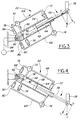
- the adjustment link 50 is shown in detail and at various stages of operation in Figures 3-6.
- the stem portion 56 includes an integral piston 58 sealingly and slidably engaging the internal wall 60 of cylinder 54.
- a first hydraulic chamber 62 is provided on one side of piston 58 and a second hydraulic chamber 64 is provided on the other side of piston 58.
- a pair of hydraulic passages 66,68 are provided for transferring fluid from one chamber to the other.
- One such hydraulic passage 66 includes an activatable valve member 70, preferably a solenoid valve, located at the inner end of cylinder 54 and a spring biased normally closed ball-type check valve 72 at the other end thereof.
- the other hydraulic passage 68 includes an activatable valve 74, again preferably a solenoid valve, at the outer end of cylinder 54 and a spring biased normally closed ball-type check valve 76 at the inner end of the cylinder 54.
- the respective check valves 72,76 are oriented such that no fluid flow is permitted in a direction from the cylinder chambers 64,62, respectively. Only fluid flow from the opposite direction and of sufficient pressure to unseat the ball valve is permitted to flow to each respective chamber 64,62.
- Each fluid passage 66,68 also is hydraulically coupled with fluid lines 78,80, respectively, which extend from a common fluid reservoir 82 which in turn is hydraulically coupled via line 84 to a sump 86 as shown in phantom line in Figure 3 only.
- the sump 86 is the source of lubricating oil for the engine and it may include a conventional hydraulic pump or, in addition, an auxiliary hydraulic pump for supplying the lubricating oil under pressure to the adjustment link 50.
- Each fluid line 78,80 includes a normally closed spring biased ball-type check valve 88,90, respectively, identical to those 72,76 earlier described.
- Check valve 90 is normally closed to fluid flowing from reservoir 82 whereas check valve 88 is normally closed to any fluid flowing to reservoir 82. The purpose of these connections is to compensate for the difference in the piston displacements in chambers 62 and 64 and to make up for leakage.
- the connecting rod 28 being connected to the swing plate 34 by means of slide 44 is controlled by hydraulic control cylinder 54. Changing the position of the slide 44 in the slot 36 varies the stroke of the piston 22.
- the shape of the slot, i.e. linear versus arcuate, and the angle of the slot relative to slot 40 determines the compression ratio which can be optimised for each engine displacement.
- the actions of the hydraulic cylinder 54 are performed under the control of the engine control system.
- the necessary hydraulic power can be supplied by a conventional hydraulic pump as mentioned above. It can also be supplied by the forces coming from the engine piston 22 and connecting rod 28 without the need for a hydraulic pump.
- the hydraulic piston 58 being integrally connected to the stem portion 56 receives an axial force "P" from the connecting rod 28.
- P axial force
- both valves 70 and 74 are closed, no flow of oil is possible between the chambers 62 and 64. Oil in both chambers is trapped there, and the piston 58 remains in fixed position in the cylinder 54.
- the installation of the check valves 72 and 76 is such that, when the valve 70 is open, oil can flow from the chamber 62 to the chamber 64 but not back; and when the valve 74 is open, it can flow from the chamber 64 to 62 but not back.
- the basic concept takes advantage of the fact that the overall geometry of the mechanism is such that the axial force "P" transmitted from the connecting rod 28 to the stem portion 56 changes direction during each engine piston stroke.
- a downward connecting rod force "F” generates a component force "P” which strives to push the stem portion 56 with the piston 58 into the cylinder 54, thus compressing and rising the pressure of the oil in the chamber 62.
- FIGs 3 and 4 illustrate what happens when the valve 70 is open and the valve 74 remains closed.
- the cylinder 54 is in the upper part of its downward swinging motion, as shown in Figure 3, oil pressure in the chamber 62 is higher than in the chamber 64, and the pressure differential opens the check valve 72.
- Force "P” pushes the piston 58 to the left, displacing the oil from the chamber 62 to chamber 64. Since the volume displaced from the chamber 62 is larger than the volume change in the chamber 64, some of the oil is displaced through the check valve 88 into the outside system 82,86.
- FIGS 5 and 6 illustrate what happens when the valve 74 is open and the valve 70 remains closed. The process is very similar to the one described above, except that this time the piston 58 moves to the right, thus increasing the engine displacement.
Landscapes
- Engineering & Computer Science (AREA)
- Chemical & Material Sciences (AREA)
- Combustion & Propulsion (AREA)
- Mechanical Engineering (AREA)
- General Engineering & Computer Science (AREA)
- Output Control And Ontrol Of Special Type Engine (AREA)
Abstract
The present invention contemplates a mechanically simply constructed mechanism located internally of a piston engine for adjustably changing the stroke of a piston (22) over a predetermined range in response to a variety of operating control parameters. The adjustable stroke changing mechanism provides an optimum compression ratio at each change in piston stroke and over the entire range of piston stroke provided which may be varied from one piston engine to another of different performance characteristics without requiring a major change in design of the stroke changing mechanism. The stroke changing mechanism includes a swing plate (34) pivotally fixed to the engine block (14) at one end and placed intermediate the piston connection rod (28) and respective crankshaft pin at its other end, each of which are affixed to and translate within the swing plate as the piston (22) is driven to reciprocate within a piston cylinder (12). An adjustment link (50) is pivotally connected to the engine block (14) at one end and to the connecting rod (28) at its other end and at the swing plate (34). The adjustment link (50) is hydraulically controlled and actuable to vary in length and thereby change the stroke, and concurrently the compression ratio of the piston (22).
Description
- This invention relates to piston engines and apparatus for automatically varying piston stroke and compression ratio, and is particularly related to internal combustion engines including apparatus for automatically varying the stroke of the piston during operation of the engine responsive to changes in operating conditions or performance demands.
- The conventional reciprocating piston-type internal combustion engine commonly used in automotive vehicles can be significantly improved if part load throttling and friction losses are reduced. In other words, conventional engines of this type are designed such to give optimum performance at full load, wide open throttle. At less than wide open throttle, and particularly at the lower speeds, the fuel in the combustion chamber of any fixed stroke engine will be less dense. Consequently, its burning efficiency will be reduced. Further, the friction losses in a reciprocating piston-type engine remain relatively constant regardless of speed. Consequently, at the lower speeds, the friction losses are a greater proportion of the work being expended to require the performance output. Lower throttling and friction losses will provide reduced fuel consumption, i.e. greater fuel efficiency. Further, the resulting improvement in fuel efficiency can be additionally enhanced by concurrent optimisation of the compression ratio for each engine displacement.
- Variable stroke piston engines are known, such as shown for example in the following U.S. patents:
1,112,832; 1,189,312; 1,372,644; 2,653,484; 2,873,611; 2,909,163; 4,131,094; and 4,538,557. - In certain of the systems, for example, as shown in U.S. Patent No. 2,909,163, an articulated linkage is provided between the crankshaft pin and the piston connecting rod that allows for varying the piston stroke while maintaining a constant piston clearance with the cylinder head (as is useful in compressor applications), or varying the piston clearance with each change in piston stroke. Adjustment of the stroke is effected manually on the exterior of the engine block or frame.
- Manual adjustment is common to the remaining aforementioned patents with the exception of U.S. Patent No. 4,131,094 wherein there is shown a system for automatically adjusting the piston stroke in accordance with different density of the fuel-air charges to be inducted into the combustion chamber.
- The present invention contemplates a mechanically simply constructed mechanism located internally of a piston engine for adjustably changing the stroke of a piston over a predetermined range.
- According to the invention there is provided a variable displacement engine comprising:
an engine block having a crank axis and a cylin der bore lying in a plane generally perpendicular to the crank axis;
a piston sealing co-operating with a cylinder bore for a reciprocal movement therein;
a crankshaft supported by the engine block and rotatable about the crank axis, said crankshaft having a crank pin radially spaced from said crank axis;
an elongated connected rod having a first end pivotably attached to the piston and a second end spaced therefrom movable along an arcuate path lying in said plane;
a lever having a fixed end pivotably attached to the block and a free end movable within said plane, said lever co-operating with the connecting rod second end to permit relative rotation and limited translation along a first path and co-operating with the crank pin to permit relative rotation and limited translation along a second path;
a link having a fixed end and a free end, one said link end being pivotably connected to the block and the other said link end being pivotably connected to the connecting rod second end; and
adjustment means for adjusting the length of the link relative to the lever to vary the reciprocal stroke of the piston in order to vary engine displacement. - The engine embodying the invention provides the optimum compression ratio at each change in piston stroke and over the entire range of piston stroke provided, and wherein modifications of the relationship of the compression ratio to piston stroke may be varied from one piston engine to another of different performance characteristics without requiring a major change in design of the stroke changing mechanism. The stroke changing mechanism is particularly suitable for high production, high performance internal combustion engines including automotive engine applications. Further the stroke changing mechanism is constructed completely internally of the engine and capable of automatic control as determined by the engine control system and in response to a variety of operating control parameters.
- Preferably, the adjustment means for the stroke changing mechanism includes a hydraulic cylinder under hydraulic control utilising the engine fluid system as a source of hydraulic fluid and utilising torque pulses within such system during operation of the engine to pump fluid through the adjustment mechanism. The control system as above described includes a sensor installed in the hydraulic cylinder which provides a feedback signal for monitoring the position of the hydraulic cylinder piston.
- The motion of the piston in the hydraulic cylinder is accomplished by permitting selective fluid flow from one hydraulic chamber of the cylinder to another, taking advantage of intermittent hydraulic pressure pulses in the two hydraulic chambers.
- The adjustment means, in one embodiment of the invention, includes a hydraulic cylinder and an internal reciprocating piston with a stem portion of the piston being integral with the adjusting link and defining a hydraulic chamber on each side of the piston. Selective oil flow from one hydraulic chamber to the other is accomplished through one of two hydraulic passages, each comprising an activatable valve and a check valve. Means are provided to open and close each activatable valve. The opening of one activatable valve while the second is closed causes oil to flow from the first hydraulic chamber to the second hydraulic chamber. Opening of the second activatable valve while the first is closed causes the oil to flow from the second hydraulic chamber to the first. Two additional check valves may be a4032Hto connect the hydraulic passages to an outside source of oil to compensate for differences in volume displacement in the two hydraulic chambers and to replenish oil that may have leaked out of the system.
- The invention will now be described further, by way of example, with reference to the accompanying drawings, in which :
- Figure 1 is a schematic diagram of the piston stroke changing mechanism in accordance with the present invention as applied to a piston engine having a single reciprocating piston and showing the piston at top dead-centre position;
- Figure 2 is a schematic diagram similar to Figure 1 showing the piston at bottom dead-centre position and at the same fixed stroke length as shown in Figure 1;
- Figure 3 is a partially schematic view of the hydraulic adjustment member for adjusting the position of the connecting rod on the swing plate in accordance with the present invention and showing a condition in which the piston stroke is shortened and engine displacement reduced;
- Figure 4 is a view similar to Figure 3 showing the same operating condition at a different point in the stroke of the engine;
- Figure 5 is a view similar to Figure 3 and illustrating the control mechanism in a state allowing the piston stroke to be increased thereby increasing engine displacement; and
- Figure 6 is a view similar to Figure 5 at a different point in the stroke of the piston.
- As mentioned above, this invention in one preferred form is particularly directed to an internal combustion engine with continuously variable displacement in which the compression ratio is also varied concurrently with change in displacement to assure the best combination of the two parameters for each engine operating condition.
- Figure 1 shows a schematic diagram of such a mechanism which performs simultaneous change of displacement and compression ratio during engine operation.
- For illustrative purposes, only a single piston and piston cylinder assembly is shown. The assembly, generally designated 10, includes a
piston cylinder 12 within anengine block 14 and acylinder head 16 secured to the engine block at the top of the cylinder and providing acombustion chamber 18 between thevalve head 20 and the top of apiston 22. Piston 22 reciprocates within thecylinder 12 as controlled by the speed of thecrankshaft 24 which is supported by theengine block 14 and revolves about acrank axis 26. - Piston 22 is connected to the
crankshaft 24 by means of an elongate connectingrod 28 having a first end pivotally attached to the piston via acylindrical piston pin 30 as in conventional construction. At its opposite end, or second end, the connecting rod is pivotally connected by means of apin 32 to a lever orswing plate 34 within aslot 36 which defines a first path. Theswing plate 34 is supported by theengine block 14 at apivot pin 38. -
Swing plate 34 includes asecond slot 40, defining a second path, within which thecrank pin 42 ofcrankshaft 24 is pivotally secured. - Within each
slot slide element 44 having sides which are in constant sliding engagement with theinternal walls 46 defining each slot.Pins slot - As noted below, varying the angle a will vary the rate of change of compression ratio relative to a change in piston stroke. Further, at least the
first slot 36 need not be linear. However, if arcuately shaped, an annular rotary slide wheel would be substituted for theslide block 44. Thus, various swing plate slot configuration can be substituted for that shown dependent upon the piston stroke-to-compression ratio characteristics desired. - The
assembly 10 further includes an adjustment link, generally designated 50, which is pivotally affixed to theengine block 14 at one end viapin 52 and pivotally connected to the connectingrod 28 at its other end viapin 32. -
Adjustment link 50 basically comprises a fixedcylinder 54 and an adjustablyreciprocable stem portion 56. Thecylinder 54 is fixed to the engine block viapin 52. Thestem portion 56 is integral with a hydraulically actuable reciprocable piston (not shown in Figures 1 and 2) within thecylinder 54. - As explained in detail below, the stroke of the
piston 22 is varied by hydraulically adjusting the length of thestem portion 56 such that the connecting rod, at top dead centre position as shown in Figure 1 will reside withinslot 36 somewhere between the position shown in solid line and position b shown in phantom line. As thepin 32 and theslide element 44 move to the right toward the position b, the length of the arc described by thepin 32 about thepin 52 increases. This increases the stroke of thepiston 22. At bottom dead centre as shown in Figure 2 it will be seen that the connecting rod second end has slid from its TDC position shown in Figure 1 to the point c shown in solid line in Figure 2 and in phantom line in Figure 1. - The
adjustment link 50 is shown in detail and at various stages of operation in Figures 3-6. Looking at Figure 3, for example, thestem portion 56 includes anintegral piston 58 sealingly and slidably engaging theinternal wall 60 ofcylinder 54. A firsthydraulic chamber 62 is provided on one side ofpiston 58 and a secondhydraulic chamber 64 is provided on the other side ofpiston 58. A pair ofhydraulic passages hydraulic passage 66 includes anactivatable valve member 70, preferably a solenoid valve, located at the inner end ofcylinder 54 and a spring biased normally closed ball-type check valve 72 at the other end thereof. The otherhydraulic passage 68 includes anactivatable valve 74, again preferably a solenoid valve, at the outer end ofcylinder 54 and a spring biased normally closed ball-type check valve 76 at the inner end of thecylinder 54. Therespective check valves cylinder chambers respective chamber - Each
fluid passage fluid lines common fluid reservoir 82 which in turn is hydraulically coupled vialine 84 to asump 86 as shown in phantom line in Figure 3 only. Preferably, thesump 86 is the source of lubricating oil for the engine and it may include a conventional hydraulic pump or, in addition, an auxiliary hydraulic pump for supplying the lubricating oil under pressure to theadjustment link 50. Eachfluid line type check valve valve 90 is normally closed to fluid flowing fromreservoir 82 whereascheck valve 88 is normally closed to any fluid flowing toreservoir 82. The purpose of these connections is to compensate for the difference in the piston displacements inchambers - In operation, looking at Figures 1 and 2 initially, the pressure force generated in the
engine cylinder 12 is transmitted to thecrankshaft 24 through thepiston 22, connectingrod 28, andswing plate 34. - The connecting
rod 28 being connected to theswing plate 34 by means ofslide 44 is controlled byhydraulic control cylinder 54. Changing the position of theslide 44 in theslot 36 varies the stroke of thepiston 22. The shape of the slot, i.e. linear versus arcuate, and the angle of the slot relative to slot 40 determines the compression ratio which can be optimised for each engine displacement. - The actions of the
hydraulic cylinder 54 are performed under the control of the engine control system. The necessary hydraulic power can be supplied by a conventional hydraulic pump as mentioned above. It can also be supplied by the forces coming from theengine piston 22 and connectingrod 28 without the need for a hydraulic pump. - The
hydraulic piston 58 being integrally connected to thestem portion 56 receives an axial force "P" from the connectingrod 28. When bothvalves chambers piston 58 remains in fixed position in thecylinder 54. The installation of thecheck valves valve 70 is open, oil can flow from thechamber 62 to thechamber 64 but not back; and when thevalve 74 is open, it can flow from thechamber 64 to 62 but not back. - The basic concept takes advantage of the fact that the overall geometry of the mechanism is such that the axial force "P" transmitted from the connecting
rod 28 to thestem portion 56 changes direction during each engine piston stroke. When thecylinder 54 is in the upper part of its swinging motion, as shown in Figures 3 and 5, a downward connecting rod force "F" generates a component force "P" which strives to push thestem portion 56 with thepiston 58 into thecylinder 54, thus compressing and rising the pressure of the oil in thechamber 62. When thecylinder 54 is in the lower part of its swinging motion, as shown in Figures 4 and 6, the same downward force "F" would generate an oppositely directed force "P" which strives to pull thestem portion 56 with thepiston 58 out of thecylinder 54, thus compressing the oil in thechamber 64. - Figures 3 and 4 illustrate what happens when the
valve 70 is open and thevalve 74 remains closed. When thecylinder 54 is in the upper part of its downward swinging motion, as shown in Figure 3, oil pressure in thechamber 62 is higher than in thechamber 64, and the pressure differential opens thecheck valve 72. Force "P" pushes thepiston 58 to the left, displacing the oil from thechamber 62 tochamber 64. Since the volume displaced from thechamber 62 is larger than the volume change in thechamber 64, some of the oil is displaced through thecheck valve 88 into theoutside system - When the
cylinder 54 is in the lower part of its downward swinging motion, as shown in Figure 4, oil pressure in thechamber 64 is higher than in thechamber 62, and thecheck valve 72 closes. Force "P" strives to move thepiston 58 to the right, but the oil trapped in thechamber 64 prevents this motion. Therefore, as long as thevalve 70 remains open, thepiston 58 moves to the left and only to the left. As a result, the stroke of the engine piston shortens, and the engine displacement is reduced. Closing of thevalve 70 stops the change of displacement. Asensor 92 installed in the bottom of thecylinder 54 monitors the distance to thepiston 58, which is a measure of the engine displacement, and provides the control system with a feedback signal. - Figures 5 and 6 illustrate what happens when the
valve 74 is open and thevalve 70 remains closed. The process is very similar to the one described above, except that this time thepiston 58 moves to the right, thus increasing the engine displacement. - It should be understood that although the above description was written as applied to a piston-type engine, it is also applicable to other types of machines and mechanisms such as, for example, piston-type compressors.
Claims (10)
- A variable displacement engine comprising:
an engine block (14) having a crank axis (26) and a cylinder bore (12) lying in a plane generally perpendicular to the crank axis;
a piston (22) sealing co-operating with a cylinder bore (12) for a reciprocal movement therein;
a crankshaft (24) supported by the engine block (14) and rotatable about the crank axis, said crankshaft having a crank pin radially spaced from said crank axis;
an elongated connected rod (28) having a first end pivotably attached to the piston and a second end spaced therefrom movable along an arcuate path lying in said plane;
a lever (34) having a fixed end pivotably attached to the block (14) and a free end movable within said plane, said lever (34) co-operating with the connecting rod second end to permit relative rotation and limited translation along a first path and co-operating with the crank pin to permit relative rotation and limited translation along a second path;
a link (50) having a fixed end and a free end, one said link end being pivotably connected to the block (14) and the other said link end being pivotably connected to the connecting rod (28) second end; and
adjustment means (54,56) for adjusting the length of the link (50) relative to the lever (34) to vary the reciprocal stroke of the piston (22) in order to vary engine displacement. - An engine as claimed in claim 1 wherein said lever is a plate member, said plate member being disposed within said plane and including a first elongated slot defining a guide surface along said first path;
said second end of the connecting rod being secured within the first elongated slot and adapted to slide along said guide surface from a top dead centre piston position to a bottom dead centre piston position. - An engine as claimed in claim 2 wherein said adjustment means includes means for adjusting the position of the second end of the connecting rod within said elongated slot.
- An engine as claimed in claim 3 wherein the fixed end of the link is pivotally connected to the block and the free end of the link is pivotally connected to the connecting rod second end.
- An engine as claimed in claim 1 wherein said adjustment means includes a hydraulic control cylinder having a housing and a hydraulic piston member reciprocable within the housing, said hydraulic piston member and housing defining a first hydraulic chamber on one side of said hydraulic piston member and a second chamber on the other side of said piston;
said link being connected to one of the housing and hydraulic piston members; and
fluid transfer means for transferring fluid under pressure from one chamber to the other to thereby adjust the length of said link relative to said fixed end and thus to the lever. - An engine as claimed in claim 5 wherein said fluid transfer means includes first and second hydraulic lines extending between the two chambers, a valve member within one said hydraulic line and hydraulically coupled to one said chamber, a first check valve member interposed in said one hydraulic line between said first valve member and the other said chamber, said first check valve member being normally closed and automatically open to the flow of fluid under pressure from said one chamber to the other;
a second valve member within the other said hydraulic line and hydraulically coupled to the other chamber, a second check valve member interposed in said one hydraulic line between said second valve member and the one said chamber, said second check valve member being normally closed and automatically open to the flow of fluid under pressure from the other said chamber to the one said chamber. - An engine as claimed in claim 6, further including a fluid reservoir for providing fluid under pressure to said adjustment means and for providing a sump for fluid discharged from one of said two chambers.
- An engine as claimed in claim 6, further including control means for selectively opening and closing each of said valve members to cause said hydraulic piston member to translate within the housing.
- An engine as claimed in claim 7, wherein said fluid reservoir is common to the engine oil lubricating system.
- An engine as claimed in claim 6, wherein said adjustment means includes a sensor for monitoring the distance the link travels in either direction when one of said valve members is opened to allow fluid flow between said two chambers, said sensor providing a feedback signal to control the travel of the hydraulic piston member at a prescribed location within the hydraulic housing.
Applications Claiming Priority (2)
| Application Number | Priority Date | Filing Date | Title |
|---|---|---|---|
| US07/720,074 US5136987A (en) | 1991-06-24 | 1991-06-24 | Variable displacement and compression ratio piston engine |
| US720074 | 2010-03-09 |
Publications (1)
| Publication Number | Publication Date |
|---|---|
| EP0520637A1 true EP0520637A1 (en) | 1992-12-30 |
Family
ID=24892527
Family Applications (1)
| Application Number | Title | Priority Date | Filing Date |
|---|---|---|---|
| EP92305199A Withdrawn EP0520637A1 (en) | 1991-06-24 | 1992-06-05 | Variable displacement and compression ratio piston engine |
Country Status (3)
| Country | Link |
|---|---|
| US (1) | US5136987A (en) |
| EP (1) | EP0520637A1 (en) |
| CA (1) | CA2068585A1 (en) |
Cited By (5)
| Publication number | Priority date | Publication date | Assignee | Title |
|---|---|---|---|---|
| FR2763097A1 (en) * | 1997-05-09 | 1998-11-13 | Vianney Paul Rabhi | DEVICE FOR CONTROLLING THE POSITION OF THE CONTROL RACK OF A VARIABLE CYLINDER MOTOR |
| FR2763096A1 (en) * | 1997-05-09 | 1998-11-13 | Vianney Paul Rabhi | IC engine with variable cylinder capacity or volume ratio |
| WO2001040641A1 (en) | 1999-11-30 | 2001-06-07 | Michel Marchisseau | Method and device for modifying compression rate to optimize operating conditions of reciprocating piston engines |
| WO2006059100A2 (en) * | 2004-11-30 | 2006-06-08 | David John Mason | Improvements to reciprocating machines |
| WO2012013262A1 (en) * | 2010-07-28 | 2012-02-02 | Daimler Ag | Method for operating a reciprocating piston engine |
Families Citing this family (43)
| Publication number | Priority date | Publication date | Assignee | Title |
|---|---|---|---|---|
| US5201287A (en) * | 1992-08-03 | 1993-04-13 | Blish Nelson A | Variable stroke internal combustion engine |
| US5335632A (en) * | 1993-05-14 | 1994-08-09 | Hefley Carl D | Variable compression internal combustion engine |
| US5406911A (en) * | 1993-08-12 | 1995-04-18 | Hefley; Carl D. | Cam-on-crankshaft operated variable displacement engine |
| US5526778A (en) * | 1994-07-20 | 1996-06-18 | Springer; Joseph E. | Internal combustion engine module or modules having parallel piston rod assemblies actuating oscillating cylinders |
| US5553582A (en) * | 1995-01-04 | 1996-09-10 | Speas; Danny E. | Nutating disc engine |
| US6109135A (en) * | 1995-12-27 | 2000-08-29 | Karsdon; Jeffrey | Tetrahelical/curved bicycle crank arm/connecting rod for human/mechanical powered machines and the like |
| US5724935A (en) * | 1996-01-11 | 1998-03-10 | Routery; Edward E. | Reciprocating piston assembly |
| US5682844A (en) * | 1996-12-30 | 1997-11-04 | Wittner; John A. | Twin crankshaft mechanism with arced connecting rods |
| US6446587B1 (en) * | 1997-09-15 | 2002-09-10 | R. Sanderson Management, Inc. | Piston engine assembly |
| US7007589B1 (en) * | 1997-09-15 | 2006-03-07 | R. Sanderson Management, Inc. | Piston assembly |
| US6460450B1 (en) | 1999-08-05 | 2002-10-08 | R. Sanderson Management, Inc. | Piston engine balancing |
| US6045339A (en) * | 1998-01-20 | 2000-04-04 | Berg; John L. | Wave motor |
| US5975043A (en) * | 1998-03-25 | 1999-11-02 | Bloomquist; Victor Rudolph | Double shaft high torque engine |
| US6289857B1 (en) * | 2000-02-23 | 2001-09-18 | Ford Global Technologies, Inc. | Variable capacity reciprocating engine |
| AT411844B (en) * | 2000-05-29 | 2004-06-25 | Kocsisek Karl | HOT GAS ENGINE |
| US7011469B2 (en) * | 2001-02-07 | 2006-03-14 | R. Sanderson Management, Inc. | Piston joint |
| JP2002285877A (en) * | 2001-03-28 | 2002-10-03 | Nissan Motor Co Ltd | Piston drive for internal combustion engine |
| US6854377B2 (en) | 2001-11-02 | 2005-02-15 | R. Sanderson Management, Inc. | Variable stroke balancing |
| US6622672B1 (en) * | 2002-08-19 | 2003-09-23 | Ford Global Technologies, L.L.C. | Variable compression ratio control system for an internal combustion engine |
| US6938589B2 (en) * | 2002-11-07 | 2005-09-06 | Powervantage Engines, Inc. | Variable displacement engine |
| AU2003900003A0 (en) * | 2003-01-02 | 2003-01-16 | Scalzo Automotive Research Pty Ltd | Piston De-activation Mechanism for Internal Combustion Engines |
| WO2004061270A1 (en) * | 2003-01-02 | 2004-07-22 | Scalzo Automotive Research Pty Ltd. | Mechanism for internal combustion piston engines |
| US6736091B1 (en) * | 2003-01-06 | 2004-05-18 | Ford Global Technologies, Llc | Variable compression ratio control system for internal combustion engine |
| US7563076B2 (en) * | 2004-10-27 | 2009-07-21 | Halliburton Energy Services, Inc. | Variable rate pumping system |
| US7409901B2 (en) * | 2004-10-27 | 2008-08-12 | Halliburton Energy Services, Inc. | Variable stroke assembly |
| FR2881513B1 (en) * | 2005-02-03 | 2007-04-06 | Sagem | COLD MACHINE OPERATING FOLLOWING THE STIRLING CYCLE |
| US7270092B2 (en) * | 2005-08-12 | 2007-09-18 | Hefley Carl D | Variable displacement/compression engine |
| US20070044739A1 (en) * | 2005-08-30 | 2007-03-01 | Caterpillar Inc. | Machine with a reciprocating piston |
| US7328682B2 (en) * | 2005-09-14 | 2008-02-12 | Fisher Patrick T | Efficiencies for piston engines or machines |
| US7159544B1 (en) | 2005-10-06 | 2007-01-09 | Studdert Andrew P | Internal combustion engine with variable displacement pistons |
| DE102006003737B3 (en) * | 2006-01-24 | 2007-06-06 | Iav Gmbh Ingenieurgesellschaft Auto Und Verkehr | Reciprocating-piston combustion engine, has piston connected to pulling and pressing rod guided parallel to cylinder axis and pulling and pressing rod interacts with transmission lever along extended channel |
| FR2914951B1 (en) | 2007-04-16 | 2012-06-15 | Vianney Rabhi | ELECTROHYDRAULIC DEVICE FOR CLOSED LOOP DRIVING OF THE CONTROL JACK OF A VARIABLE COMPRESSION RATE MOTOR. |
| CN101784775B (en) * | 2007-07-09 | 2013-03-27 | 斯卡尔佐汽车研究股份有限公司 | Mechanism for internal combustion piston engines |
| US7827943B2 (en) * | 2008-02-19 | 2010-11-09 | Tonand Brakes Inc | Variable compression ratio system |
| US8468997B2 (en) * | 2009-08-06 | 2013-06-25 | Larry C. Wilkins | Internal combustion engine with variable effective length connecting rod |
| KR101198785B1 (en) * | 2010-07-13 | 2012-11-07 | 현대자동차주식회사 | Variable compression ratio apparatus |
| US20120312273A1 (en) * | 2011-06-10 | 2012-12-13 | Robert T. Weverka | Internal combustion engine with torsional element |
| CN102583069A (en) * | 2012-03-06 | 2012-07-18 | 褚建祥 | Material balancing swing plate driving device used for feeding bin |
| US9062613B1 (en) * | 2014-02-19 | 2015-06-23 | Hi-Tech Forward, L.L.C. | Variable stroke and compression ratio internal combustion engine |
| WO2016176334A1 (en) * | 2015-04-28 | 2016-11-03 | Wladyslaw Kurek | Improved internal combustion engine |
| FR3038340A1 (en) * | 2015-07-01 | 2017-01-06 | Voisine Marc Claude | MECHANICAL DEVICE IMPROVING THE ADJUSTMENT OF A BALANCER MOVEMENT AND TORQUE ON THE CRANKSHAFT OF THE INVERSION OF THE TRANSLATION OF THE COMPRESSED GAS PISTON |
| JP6672997B2 (en) * | 2016-05-02 | 2020-03-25 | 日産自動車株式会社 | Internal combustion engine with variable compression ratio mechanism |
| CN110410211B (en) * | 2019-06-20 | 2021-11-02 | 江苏雨燕模业科技股份有限公司 | Engine system with adjustable stroke |
Citations (4)
| Publication number | Priority date | Publication date | Assignee | Title |
|---|---|---|---|---|
| BE354633A (en) * | ||||
| FR361271A (en) * | 1905-10-19 | 1906-05-29 | Charles Edouard Henriod | Mechanism automatically varying the stroke of any valve or rod |
| GB191229465A (en) * | 1912-12-21 | 1913-10-16 | Clarence William Crossley | Improvements in Internal Combustion Engines. |
| US2390558A (en) * | 1944-03-07 | 1945-12-11 | Edward H Schoen | Engine crankshaft to piston connecting mechanism |
Family Cites Families (11)
| Publication number | Priority date | Publication date | Assignee | Title |
|---|---|---|---|---|
| US1372644A (en) * | 1921-03-22 | Internal-combustion engine | ||
| DE207108C (en) * | ||||
| US1112832A (en) * | 1913-04-23 | 1914-10-06 | John Stuart Westney | Variable-stroke mechanism. |
| US1189312A (en) * | 1916-02-23 | 1916-07-04 | William G Tibbels | Engine. |
| FR720427A (en) * | 1930-05-20 | 1932-02-19 | Adjustment device for compression chamber of internal combustion engines | |
| US2653484A (en) * | 1950-09-05 | 1953-09-29 | Zecher Ernest | Compensating mechanism connecting reciprocating member to a rotating member |
| US2909163A (en) * | 1955-07-01 | 1959-10-20 | Arnold E Biermann | Variable stroke piston engines |
| US2873611A (en) * | 1955-07-01 | 1959-02-17 | Arnold E Biermann | Variable stroke mechanisms |
| US2822791A (en) * | 1955-07-01 | 1958-02-11 | Arnold E Biermann | Variable stroke piston engines |
| US4131094A (en) * | 1977-02-07 | 1978-12-26 | Crise George W | Variable displacement internal combustion engine having automatic piston stroke control |
| US4538557A (en) * | 1983-03-24 | 1985-09-03 | Kleiner Rudolph R | Internal combustion engine |
-
1991
- 1991-06-24 US US07/720,074 patent/US5136987A/en not_active Expired - Fee Related
-
1992
- 1992-05-13 CA CA002068585A patent/CA2068585A1/en not_active Abandoned
- 1992-06-05 EP EP92305199A patent/EP0520637A1/en not_active Withdrawn
Patent Citations (4)
| Publication number | Priority date | Publication date | Assignee | Title |
|---|---|---|---|---|
| BE354633A (en) * | ||||
| FR361271A (en) * | 1905-10-19 | 1906-05-29 | Charles Edouard Henriod | Mechanism automatically varying the stroke of any valve or rod |
| GB191229465A (en) * | 1912-12-21 | 1913-10-16 | Clarence William Crossley | Improvements in Internal Combustion Engines. |
| US2390558A (en) * | 1944-03-07 | 1945-12-11 | Edward H Schoen | Engine crankshaft to piston connecting mechanism |
Non-Patent Citations (1)
| Title |
|---|
| RESEARCH DISCLOSURE. vol. 152, 1 December 1976, HAVANT GB pages 31 - 33; ANONYMOUSLY: 'VARIABLE DISPLACEMENT ENGINES' * |
Cited By (10)
| Publication number | Priority date | Publication date | Assignee | Title |
|---|---|---|---|---|
| FR2763097A1 (en) * | 1997-05-09 | 1998-11-13 | Vianney Paul Rabhi | DEVICE FOR CONTROLLING THE POSITION OF THE CONTROL RACK OF A VARIABLE CYLINDER MOTOR |
| FR2763096A1 (en) * | 1997-05-09 | 1998-11-13 | Vianney Paul Rabhi | IC engine with variable cylinder capacity or volume ratio |
| WO1998051911A1 (en) * | 1997-05-09 | 1998-11-19 | Vianney Rabhi | Device for varying a piston engine effective volumetric displacement and/or volumetric ratio of during its operation |
| AU723539B2 (en) * | 1997-05-09 | 2000-08-31 | Vianney Rabhi | Device for varying a piston engine effective volumetric displacement and/or volumetric ratio during its operation |
| US6354252B1 (en) | 1997-05-09 | 2002-03-12 | Vianney Paul Rabhi | Device for varying a piston engine effective volumetric displacement and/or volumetric ratio of during its operation |
| WO2001040641A1 (en) | 1999-11-30 | 2001-06-07 | Michel Marchisseau | Method and device for modifying compression rate to optimize operating conditions of reciprocating piston engines |
| WO2006059100A2 (en) * | 2004-11-30 | 2006-06-08 | David John Mason | Improvements to reciprocating machines |
| WO2006059100A3 (en) * | 2004-11-30 | 2006-08-10 | David John Mason | Improvements to reciprocating machines |
| WO2012013262A1 (en) * | 2010-07-28 | 2012-02-02 | Daimler Ag | Method for operating a reciprocating piston engine |
| CN103026030A (en) * | 2010-07-28 | 2013-04-03 | 戴姆勒股份公司 | Method for operating a reciprocating piston engine |
Also Published As
| Publication number | Publication date |
|---|---|
| US5136987A (en) | 1992-08-11 |
| CA2068585A1 (en) | 1992-12-25 |
Similar Documents
| Publication | Publication Date | Title |
|---|---|---|
| US5136987A (en) | Variable displacement and compression ratio piston engine | |
| US6354252B1 (en) | Device for varying a piston engine effective volumetric displacement and/or volumetric ratio of during its operation | |
| US5187835A (en) | Door closer with rack and pinion, spring, and spring mounting plate | |
| US5127375A (en) | Hydraulic valve control system for internal combustion engines | |
| US7021254B2 (en) | Engine with variably adjustable compression ratio, and methods of using same | |
| CA1180963A (en) | Automatic compression adjusting mechanism for internal combustion engines | |
| EP0340821B1 (en) | Automatic timing variation device for an internal combustion engine | |
| EP0801213A1 (en) | Hydraulic actuator and variable valve driving mechanism making use of the same | |
| CA2493093A1 (en) | Piston-in-piston variable compression ratio engine | |
| US3970056A (en) | Variable compression ratio control system for internal combustion engines | |
| SE501437C2 (en) | Valve mechanism in an internal combustion engine | |
| KR890008449A (en) | Swash plate compressor with variable displacement mechanism | |
| US5257600A (en) | Variable compression piston | |
| US5666913A (en) | Variable timing cam follower lever assembly | |
| KR940011712B1 (en) | Clutchless compressor | |
| US4582029A (en) | Valve timing control system for internal combustion engine | |
| US6595170B2 (en) | Hydraulic valve-operating mechanism | |
| US6244227B1 (en) | Valve assembly using pressurized medium for controlling operating conditions of a two-stroke engine | |
| CN108019278B (en) | Connecting rod with a closed component group for length adjustment | |
| CA1102643A (en) | Hydraulic valve lifter | |
| EP0309468B1 (en) | Variable actuator for a valve | |
| US6988470B2 (en) | Swash plate combustion engine and method | |
| US4346677A (en) | Combustion engine with substantially constant compression | |
| US4559909A (en) | Valve mechanism for an internal combustion engine | |
| US4342291A (en) | Expandable piston motor |
Legal Events
| Date | Code | Title | Description |
|---|---|---|---|
| PUAI | Public reference made under article 153(3) epc to a published international application that has entered the european phase |
Free format text: ORIGINAL CODE: 0009012 |
|
| AK | Designated contracting states |
Kind code of ref document: A1 Designated state(s): DE FR GB |
|
| STAA | Information on the status of an ep patent application or granted ep patent |
Free format text: STATUS: THE APPLICATION IS DEEMED TO BE WITHDRAWN |
|
| 18D | Application deemed to be withdrawn |
Effective date: 19930630 |