EP0519112B1 - Reflector and method of generating a reflector shape - Google Patents
Reflector and method of generating a reflector shape Download PDFInfo
- Publication number
- EP0519112B1 EP0519112B1 EP91110286A EP91110286A EP0519112B1 EP 0519112 B1 EP0519112 B1 EP 0519112B1 EP 91110286 A EP91110286 A EP 91110286A EP 91110286 A EP91110286 A EP 91110286A EP 0519112 B1 EP0519112 B1 EP 0519112B1
- Authority
- EP
- European Patent Office
- Prior art keywords
- reflector
- segments
- curve
- conic
- intersection
- Prior art date
- Legal status (The legal status is an assumption and is not a legal conclusion. Google has not performed a legal analysis and makes no representation as to the accuracy of the status listed.)
- Expired - Lifetime
Links
- 238000000034 method Methods 0.000 title claims description 13
- 230000005855 radiation Effects 0.000 claims description 50
- 238000009826 distribution Methods 0.000 claims description 42
- 230000003287 optical effect Effects 0.000 claims description 14
- 238000005304 joining Methods 0.000 claims description 4
- 238000010276 construction Methods 0.000 description 12
- 230000007704 transition Effects 0.000 description 7
- 238000004519 manufacturing process Methods 0.000 description 6
- 238000012986 modification Methods 0.000 description 6
- 230000004048 modification Effects 0.000 description 6
- 230000008859 change Effects 0.000 description 5
- 238000006073 displacement reaction Methods 0.000 description 4
- 230000004313 glare Effects 0.000 description 4
- 229920001817 Agar Polymers 0.000 description 3
- 230000008901 benefit Effects 0.000 description 3
- 241001523162 Helle Species 0.000 description 2
- 238000013459 approach Methods 0.000 description 2
- 238000004364 calculation method Methods 0.000 description 2
- 238000013461 design Methods 0.000 description 2
- 230000006872 improvement Effects 0.000 description 2
- 238000002686 lithotriptor Methods 0.000 description 2
- 230000035939 shock Effects 0.000 description 2
- 240000003380 Passiflora rubra Species 0.000 description 1
- 230000015556 catabolic process Effects 0.000 description 1
- 238000005520 cutting process Methods 0.000 description 1
- 230000001419 dependent effect Effects 0.000 description 1
- 238000011161 development Methods 0.000 description 1
- 230000005670 electromagnetic radiation Effects 0.000 description 1
- 238000005516 engineering process Methods 0.000 description 1
- 238000002474 experimental method Methods 0.000 description 1
- 238000005286 illumination Methods 0.000 description 1
- 238000011835 investigation Methods 0.000 description 1
- 238000007620 mathematical function Methods 0.000 description 1
- 238000005488 sandblasting Methods 0.000 description 1
- 230000003595 spectral effect Effects 0.000 description 1
- 239000004575 stone Substances 0.000 description 1
Images


Classifications
-
- G—PHYSICS
- G02—OPTICS
- G02B—OPTICAL ELEMENTS, SYSTEMS OR APPARATUS
- G02B5/00—Optical elements other than lenses
- G02B5/08—Mirrors
- G02B5/10—Mirrors with curved faces
-
- F—MECHANICAL ENGINEERING; LIGHTING; HEATING; WEAPONS; BLASTING
- F21—LIGHTING
- F21S—NON-PORTABLE LIGHTING DEVICES; SYSTEMS THEREOF; VEHICLE LIGHTING DEVICES SPECIALLY ADAPTED FOR VEHICLE EXTERIORS
- F21S41/00—Illuminating devices specially adapted for vehicle exteriors, e.g. headlamps
- F21S41/30—Illuminating devices specially adapted for vehicle exteriors, e.g. headlamps characterised by reflectors
- F21S41/32—Optical layout thereof
- F21S41/33—Multi-surface reflectors, e.g. reflectors with facets or reflectors with portions of different curvature
- F21S41/331—Multi-surface reflectors, e.g. reflectors with facets or reflectors with portions of different curvature the reflector consisting of complete annular areas
- F21S41/332—Multi-surface reflectors, e.g. reflectors with facets or reflectors with portions of different curvature the reflector consisting of complete annular areas with continuity at the junction between adjacent areas
-
- Y—GENERAL TAGGING OF NEW TECHNOLOGICAL DEVELOPMENTS; GENERAL TAGGING OF CROSS-SECTIONAL TECHNOLOGIES SPANNING OVER SEVERAL SECTIONS OF THE IPC; TECHNICAL SUBJECTS COVERED BY FORMER USPC CROSS-REFERENCE ART COLLECTIONS [XRACs] AND DIGESTS
- Y10—TECHNICAL SUBJECTS COVERED BY FORMER USPC
- Y10S—TECHNICAL SUBJECTS COVERED BY FORMER USPC CROSS-REFERENCE ART COLLECTIONS [XRACs] AND DIGESTS
- Y10S359/00—Optical: systems and elements
- Y10S359/90—Methods
Definitions
- the invention relates to a reflector for radiation emanating from a radiation source with a shape such that a reflector intersection curve in a plane containing an axis of the reflector and the radiation source has segments of different curved cone sections, that is to say lines that have not degenerated into straight lines, which merge into one another without edges, the cone section segments are directly joined together. Furthermore, the invention also relates to a method for producing reflector shapes.
- the reflectors in question have a wide variety of tasks. For example, it may be desirable to achieve a high energy density at a desired distance from the reflector, or a homogeneous energy distribution at a certain distance from the reflector or an exact phase adjustment may also be desired.
- radiation-directing elements such as lenses or the like
- the imperfection of the reflector shape with regard to the direction and distribution of the radiation is overcome by additional components.
- the invention relates to the design of reflector shapes using a computer.
- radiation distributions generated using a specific reflector shape can be calculated in advance using a computer.
- computers are also already used to form reflector shapes to determine.
- the computer calculations are based on conic sections and are therefore severely restricted.
- the invention shows new reflector shapes that can be determined by means of a computer.
- US-A-4 984 140 describes a reflector formed from a section of a paraboloid of revolution and a cone section, these areas being smoothly joined together.
- a reflector is disclosed which has two parabolic sections with a smoothly adjoining conical section located between them.
- EP-A-0 307 657 describes a headlight for vehicles, the reflector of which is composed of four segments of different shapes. The individual segments should merge seamlessly. The document does not teach how such a reflector with a stepless transition can be constructed without deviating from exact conical shapes.
- EP-A-0 402 740 (the inventor of the present application) teaches a method for producing different reflector shapes that are not conic curves.
- the reflector cut curves in these known reflector shapes meet the above three criteria and thus enable the construction of a reflector whose light distribution can be determined in advance and which therefore does not require an experiment to exactly determine the radiation distribution.
- a reflector according to the invention for solving this problem is characterized in that at the point of contact of two adjoining conic section segments, the tangents which can be applied to both conic section segments are the same and that the first focal points of the conic section segments fall apart.
- the piece A1 to B2 of the parabola P1 should therefore be replaced by another conic section, namely the segment A2 to B2 of the parabola P2.
- the tangents T1 at point A1 at parabola P1 and T2 at point A2 at parabola P2 are determined.
- the tangents T1, T2 each intersect the axis A at a certain angle.
- the tangents are brought into parallel position.
- segment A2-B2 of parabola P2 is rotated around point A2 until tangent T2 runs parallel to tangent T1.
- segment A2-B2 is shifted in parallel so that point A2 coincides with point A1. This is shown in Fig.2.
- the segments S1-A1 and A2-B2, each shown with a solid line, are now directly adjacent to one another, ie there is no transition piece between the conic sections.
- the result is a reflector intersection curve S1-A1 / A2-B2 (shown in Fig. 2 with a solid line), which consist entirely of conic section segments from different conic sections and which continuously merge into one another, i.e. at the contact point A1, A2 are from both directions equal tangents.
- the radiation distribution of a reflector formed according to the reflector section curve of FIG. 2 can be determined completely, since the tangent and thus the angle of incidence and angle of incidence of a beam are known for each point on the reflector surface.
- the polar beam 0-S intersects the parabolas at points A1, A2, A3, A4 and A5, whereby the tangents applied to the parabolas in these points are all parallel.
- the segment A4-B4 only needs to be shifted in parallel so that point A4 on the polar beam 0-S is transferred to point A3, which is shown in FIG. 4 is indicated by an arrow.
- the tangents are identical as desired.
Landscapes
- Physics & Mathematics (AREA)
- General Physics & Mathematics (AREA)
- Optics & Photonics (AREA)
- Engineering & Computer Science (AREA)
- General Engineering & Computer Science (AREA)
- Optical Elements Other Than Lenses (AREA)
Description
Die Erfindung betrifft einen Reflektor für von einer Strahlungsquelle ausgehende Strahlung mit einer Form derart, daß eine Reflektorschnittkurve in einer eine Achse des Reflektors und die Strahlungsquelle enthaltenden Ebene Segmente verschiedener gekrümmter, also nicht zu Geraden entarteter Kegelschnitte aufweist, die kantenfrei ineinander übergehen, wobei die Kegelabschnittsegmente direkt aneinandergefügt sind. Weiterhin betrifft die Erfindung auch ein Verfahren zum Erzeugen von Reflektorformen.The invention relates to a reflector for radiation emanating from a radiation source with a shape such that a reflector intersection curve in a plane containing an axis of the reflector and the radiation source has segments of different curved cone sections, that is to say lines that have not degenerated into straight lines, which merge into one another without edges, the cone section segments are directly joined together. Furthermore, the invention also relates to a method for producing reflector shapes.
Der Begriff Reflektor ist hier allgemein zu verstehen und betrifft nicht nur die Reflexion optischer Strahlen (elektromagnetische Wellen), sondern Reflexion im gesamten Spektralbereich sowie auch die Reflexion anderer Wellen oder Strahlen, wie z.B. Schall (insbesondere bei Lautsprechern), Stoßwellen (insbesondere bei einem Lithotriptor für die medizinische Steinzertrümmerung) oder auch das Auffangen von elektromagnetischen Wellen (z.B. Parabolantenne).The term reflector is to be understood here generally and does not only refer to the reflection of optical rays (electromagnetic waves), but also reflection in the entire spectral range as well as the reflection of other waves or rays, e.g. Sound (especially with loudspeakers), shock waves (especially with a lithotriptor for medical stone crushing) or the collection of electromagnetic waves (e.g. parabolic antenna).
Die hier in Rede stehenden Reflektoren haben unterschiedlichste Aufgaben. Beispielsweise kann es gewünscht sein, eine große Energiedichte in einem gewünschten Abstand vom Reflektor zu erreichen oder es kann auch eine homogene Energieverteilung in einem bestimmten Abstand vom Reflektor oder eine genaue Phasenabstimmung angestrebt sein.The reflectors in question have a wide variety of tasks. For example, it may be desirable to achieve a high energy density at a desired distance from the reflector, or a homogeneous energy distribution at a certain distance from the reflector or an exact phase adjustment may also be desired.
Neben diesen unterschiedlichsten Aufgabenstellungen für Reflektoren ist weiterhin zu beachten, daß regelmäßig bestimmte Randbedingungen für die Reflektoren vorgegeben sind, wie deren Abmessungen und die Abstrahlungswinkel der Strahlungsquellen.In addition to these various tasks for reflectors, it should also be noted that certain boundary conditions for the reflectors are regularly specified, such as their dimensions and the radiation angle of the radiation sources.
Aufgrund der vorstehend beschriebenen unterschiedlichen Aufgabenstellungen und Randbedingungen gibt es keine optimale Reflektorform, die universell alle Aufgaben lösen kann. In Abhängigkeit von der jeweils gestellten Aufgabe sowie den herrschenden Randbedingungen muß für jeden Anwendungsfall eine geeignete Reflektorform entwickelt werden.Due to the different tasks and boundary conditions described above, there is no optimal reflector shape that can solve all tasks universally. Depending on the task at hand and the prevailing boundary conditions, a suitable reflector shape must be developed for each application.
Im Stand der Technik werden häufig den Reflektoren strahlungslenkende Elemente (wie Linsen od. dergl.) zugeordnet, um letztlich die gewünschte Verteilung der Strahlung zu erreichen. Mit anderen Worten: die Unvollkommenheit der Reflektorform hinsichtlich der Lenkung und Verteilung der Strahlung wird durch zusätzliche Bauteile überwunden.In the prior art, radiation-directing elements (such as lenses or the like) are often assigned to the reflectors in order to ultimately achieve the desired distribution of the radiation. In other words: the imperfection of the reflector shape with regard to the direction and distribution of the radiation is overcome by additional components.
Bei der vorliegenden Erfindung geht es um Reflektorformen, welche die Verwendung von zusätzlichen strahlungslenkenden Elementen (Linsen od. dergl.) überflüssig machen, d.h. der Reflektor alleine erzeugt die gewünschte Strahlungsverteilung.The present invention relates to reflector shapes which make the use of additional radiation-directing elements (lenses or the like) superfluous, i.e. the reflector alone produces the desired radiation distribution.
Nachfolgend wird die Erfindung mit Blick auf Reflektoren für sichtbare elektromagnetische Strahlung (Licht) erläutert, jedoch lassen sich die Prinzipien ohne weiteres auf andere Reflexionsprobleme übertragen (z.B. auf die Führung von Stoßwellen in einem Lithotriptor).The invention is explained below with reference to reflectors for visible electromagnetic radiation (light), but the principles can easily be transferred to other reflection problems (e.g. to the guidance of shock waves in a lithotriptor).
Die Erfindung betrifft die Gestaltung von Reflektorformen mittels eines Computers. Grundsätzlich können mit einem Computer Strahlungsverteilungen, die mittels einer bestimmten Reflektorform erzeugt werden, vorab berechnet werden. Im Stand der Technik werden auch bereits Computer verwendet, um Reflektorformen zu bestimmen. Dabei basieren aber im Stand der Technik die Computerberechnungen auf Kegelschnitten und sind somit stark eingeschränkt. Die Erfindung zeigt neue Reflektorformen auf, die mittels eines Computers bestimmbar sind.The invention relates to the design of reflector shapes using a computer. In principle, radiation distributions generated using a specific reflector shape can be calculated in advance using a computer. In the prior art, computers are also already used to form reflector shapes to determine. In the prior art, however, the computer calculations are based on conic sections and are therefore severely restricted. The invention shows new reflector shapes that can be determined by means of a computer.
Ganz allgemein betrachtet sind bei der Konstruktion von Reflektoren folgende Gesichtspunkte (Kriterien) wesentlich:
- 1. Da bei einer Reflexion das Gesetz "Einfallswinkel gleich Ausfallswinkel" gilt, wäre es wünschenswert, einen Reflektor so zu konstruieren, daß die Tangenten an den einzelnen Stellen des Reflektors wahlweise geändert werden können.
- 2. Bei Reflektoren sollte die gesamte Form kontinuierlich glatt sein, d.h. keine Kanten aufweisen. Kantenfreiheit in diesem Sinne bedeutet, daß die Kurven "stetig differenzierbar" sind. Kanten würden helle Ringe (bei rotationssymmetrischen Reflektorformen) oder helle Streifen (bei rinnenförmigen Reflektorformen) im Lichtfleck erzeugen. In diesem Sinne bedeutet also "kantig", daß die Tangente an eine Reflektorschnittkurve, welche die zentrale Achse des Reflektors enthält, sich nicht kontinuierlich ändert, sondern sprunghaft. Durch eine solche sprunghafte Änderung überlagern sich Strahlen, die durch die vor und nach der Kante liegenden Kurvensegmente reflektiert werden, so daß die vorstehend erwähnten im allgemeinen unerwünschten hellen Ringe bzw. Streifen entstehen. Bei in dem Reflektor vorspringenden Kanten können dunkle Ringe und Streifen entstehen.
- 3. Um die von einem Reflektor erzeugte Strahlungsverteilung vorherbestimmen zu können, muß die Reflektorform so definiert sein, daß im Sinne des obigen Kriteriums (1) eine Bestimmung der Strahlungsverteilung erfolgen kann. Frei gezogene Kurven können diese Bedindung nicht erfüllen.
- 1. Since the law "angle of incidence equals angle of reflection" applies to a reflection, it would be desirable to construct a reflector in such a way that the tangents at the individual locations of the reflector can optionally be changed.
- 2. In the case of reflectors, the entire shape should be continuously smooth, ie have no edges. Edge freedom in this sense means that the curves are "continuously differentiable". Edges would create bright rings (with rotationally symmetrical reflector shapes) or bright stripes (with gutter-shaped reflector shapes) in the light spot. In this sense, "angular" means that the tangent to a reflector section curve, which contains the central axis of the reflector, does not change continuously, but rather abruptly. Such an abrupt change causes rays to be superimposed, which are reflected by the curve segments lying in front of and behind the edge, so that the above-mentioned generally undesirable bright rings or stripes are formed. If the edges protrude in the reflector, dark rings and stripes can arise.
- 3. In order to be able to predetermine the radiation distribution generated by a reflector, the reflector shape must be defined in such a way that the radiation distribution can be determined in the sense of the above criterion (1). Freely drawn curves cannot meet this requirement.
In Betracht der vorstehenden Aufgabenstellungen, Randbedingungen und Kriterien unterschiedlichster Art verwundert es nicht, daß im Stand der Technik vielfältigste Vorschläge für die Konstruktion von Reflektorformen vorliegen. Ausgangsform ist dabei regelmäßig der Kegelschnitt. Kegelschnittkurven haben den Vorteil, daß sie rechnerisch definiert und stetig sind, so daß die Strahlungsverteilung in einfacher Weise bestimmt werden kann. Allerdings haben Kegelschnittkurven (als Schnittkurven durch den Reflektor) den Nachteil, daß die Tangenten an die einzelnen Punkte des Reflektors nicht nach Bedarf geändert werden können. Vielmehr sind diese Tangenten fest vorgegeben. Beispielsweise ändert sich die an eine Parabel anlegbare Tangente über den Verlauf der Parabel so, daß vom Brennpunkt ausgestrahlte Strahlung zur optischen Achse parallel reflektiert wird. Solche Reflexionseigenschaften von kegelschnittförmigen Reflektoren können durch Änderung der Kegelschnittparameter nicht variiert werden.In view of the above tasks, boundary conditions and criteria of various kinds, it is not surprising that the prior art has a wide variety of proposals for the construction of reflector shapes. The initial form is regularly the conic section. Conic section curves have the advantage that they are mathematically defined and are continuous, so that the radiation distribution can be determined in a simple manner. However, conic intersection curves (as intersection curves through the reflector) have the disadvantage that the tangents to the individual points of the reflector cannot be changed as required. Rather, these tangents are fixed. For example, the tangent that can be applied to a parabola changes over the course of the parabola so that radiation emitted by the focal point is reflected parallel to the optical axis. Such reflection properties of conical reflectors cannot be varied by changing the conical parameters.
Eine der wichtigsten und zugleich schwierigsten Aufgaben bei Reflektoren besteht in der Erzeugung einer homogenen Strahlungsverteilung (Lichtverteilung) ausschließlich mittels der Reflektorform (also ohne zusätzliche Hilfsmittel). Keine der bekannten Kegelschnittkurven kann diese Aufgabe lösen.One of the most important and at the same time the most difficult tasks with reflectors is the generation of a homogeneous radiation distribution (light distribution) exclusively by means of the reflector shape (i.e. without additional aids). None of the known conic curves can solve this task.
Die EP-A-0 371 511 offenbart einen Reflektor gemäß dem Oberbegriff des Anspruchs 1, der aus einem Kugelabschnitt und mehreren Abschnitten von Rotationsellipsoiden zusammengesetzt ist, die möglichst glatt ineinander übergehen sollen. Der Mittelpunkt des Kugelabschnitts und die ersten Brennpunkte der Rotationsellipsoide fallen zusammen. Die zweiten Brennpunkte der Rotationsellipsoide fallen auseinander und liegen auf der Achse des Reflektors in vorbestimmten Abständen vom gemeinsamen Brennpunkt.EP-A-0 371 511 discloses a reflector according to the preamble of
In der FR-A-2 634 003 wird ein Reflektor offenbart, dessen Erzeugende aus Abschnitten von Kegelschnittkurven, nämlich von Parabeln und Ellipsen besteht, die jeweils einen gemeinsamen Brennpunkt aufweisen. Die einzelnen Abschnitte sind durch hyperbolische Zwischenbereiche miteinander verbunden. Es wird ein Näherungsverfahren angegeben, wie ein solcher Zwischenbereich zwischen zwei Ellipsen mit gemeinsamen ersten Brennpunkten eingefügt werden kann.FR-A-2 634 003 discloses a reflector whose generatrix consists of sections of conic section curves, namely parabolas and ellipses, each of which has a common focal point. The individual sections are through hyperbolic intermediate areas connected. An approximation method is specified for how such an intermediate region can be inserted between two ellipses with common first focal points.
Die US-A-4 984 140 beschreibt einen Reflektor, der aus einem Abschnitt eines Rotationsparaboloids und einem Kegelabschnitt gebildet ist, wobei diese Bereicht glatt aneinandergefügt sind. Außerdem wird ein Reflektor offenbart, der zwei parabelförmige Abschnitte mit einem dazwischen befindlichen, glatt anschließenden Kegelabschnitt aufweist.US-A-4 984 140 describes a reflector formed from a section of a paraboloid of revolution and a cone section, these areas being smoothly joined together. In addition, a reflector is disclosed which has two parabolic sections with a smoothly adjoining conical section located between them.
Die Schrift DD-A-159 809 offenbart einen asymmetrischen Reflektor für röhren- oder stabförmige Lichquellen, dessen Hauptreflektor sich aus der gradlinigen Verschiebung einer Erzeugenden ergibt. Die Erzeugende setzt sich aus zwei nur näherungsweise parabelförmigen Abschnitten zusammen, die in der Vereinigungszone fertigungstechnisch knickfrei aneinander angeglichenen sind. An beiden Seiten des Hauptreflektors sind Seitenreflektoren angeordnet. Die Lichtquelle ist zwischen den beiden Brennlinien des Hauptreflektors angeordnet.The document DD-A-159 809 discloses an asymmetrical reflector for tubular or rod-shaped light sources, the main reflector of which results from the linear displacement of a generator. The generator is made up of two only approximately parabolic sections which are aligned in the union zone in terms of production technology without kinks. Side reflectors are arranged on both sides of the main reflector. The light source is arranged between the two focal lines of the main reflector.
Die EP-A-0 307 657 beschreibt einen Scheinwerfer für Fahrzeuge, dessen Reflektor sich aus vier Segmenten verschiedener Formen zusammensetzt. Die einzelnen Segmente sollen stufenlos ineinander übergehen. Die Schrift lehrt nicht, wie ein solcher Reflektor mit stufenlosem Übergang konstruiert werden kann, ohne von exakten Kegelschnitt-Formen abzuweichen.EP-A-0 307 657 describes a headlight for vehicles, the reflector of which is composed of four segments of different shapes. The individual segments should merge seamlessly. The document does not teach how such a reflector with a stepless transition can be constructed without deviating from exact conical shapes.
In der DE-A-37 44 563 findet sich ein sehr komplizierter Ansatz für einen Kraftfahrzeugscheinwerfer, bei dem ein Teil des Reflektors als Paraboloid ausgebildet ist, während ein zentraler Abschnitt einer sehr komplizierten mathematischen Funktion folgt, wobei der Übergang zwischen unterschiedlichen Abschnitten stetig differenzierbar gestaltet sein soll.In DE-A-37 44 563 there is a very complicated approach for a motor vehicle headlight, in which a part of the reflector is designed as a paraboloid, while a central section follows a very complicated mathematical function, the transition between different sections being continuously differentiable should be.
Die DE 35 07 143 lehrt die Aneinanderreihung von Segmenten verschiedener Kegelschnitte, wobei aber das Problem des Überganges zwischen unterschiedlichen Segmenten nicht gelöst ist, d.h. es verbleiben Kanten.DE 35 07 143 teaches the lining up of segments of different conic sections, but the problem of the transition between different segments has not been solved, i.e. edges remain.
Das US-Patent 4 730 240 versucht solche Kanten zwischen unterschiedlichen parabolischen Segmenten dadurch zu vermeiden, daß der Übergang zwischen den Segmenten glatt (smoothly) gestaltet wird. Das Problem des Übergangs wird aber nicht allgemein gelöst, sondern es werden für den speziellen Fall explizit Koordinaten-Tabellen angegeben. Es wurde also nicht beschrieben, wie die Übergangskurve rechnerisch festgelegt werden kann. Somit erfüllt dieser Stand der Technik nicht das obige Kriterium (3) und die bekannte Reflektorkonstruktion ist höchst aufwendig.U.S. Patent 4,730,240 tries to avoid such edges between different parabolic segments by making the transition between the segments smooth. However, the problem of the transition is not generally solved, but coordinate tables are explicitly given for the special case. So it was not described how the transition curve can be determined mathematically. Thus, this prior art does not meet the above criterion (3) and the known reflector construction is extremely complex.
Die europäische Patentanmeldung EP-A-0 402 740 (des Erfinders der vorliegenden Anmeldung) lehrt ein Verfahren zum Erzeugen unterschiedlicher Reflektorformen, welche nicht Kegelschnittkurven sind. Die Reflektorschnittkurven bei diesen bekannten Reflektorformen erfüllen die obigen drei Kriterien und ermöglichen somit die Konstruktion eines Reflektors, dessen Lichtverteilung vorab bestimmbar ist, bei dem also kein Experiment erforderlich ist, um die Strahlungsverteilung exakt zu ermitteln.European patent application EP-A-0 402 740 (the inventor of the present application) teaches a method for producing different reflector shapes that are not conic curves. The reflector cut curves in these known reflector shapes meet the above three criteria and thus enable the construction of a reflector whose light distribution can be determined in advance and which therefore does not require an experiment to exactly determine the radiation distribution.
Das vorstehend genannte bekannte Verfahren zum Erzeugen einer Reflektorform hat allerdings den Nachteil, daß es sehr zeitaufwendig ist. Auch erscheint es hinsichtlich der Variabilität der Konstruktion verbesserungsfähig.However, the known method for producing a reflector shape mentioned above has the disadvantage that it is very time-consuming. It also appears to be subject to improvement with regard to the variability of the construction.
Der Erfindung liegt deshalb die Aufgabe zugrunde, einen Strahlungsreflektor zu schaffen sowie ein Verfahren zum Erzeugen einer Reflektorform aufzuzeigen, bei dem bzw. mit dem eine Strahlungsverteilung in gewünschter Weise ohne zusätzliche strahlungslenkende Mittel möglich ist, wobei das Verfahren möglichst vielseitig anwendbar und einfach durchführbar sein soll.The invention is therefore based on the object of providing a radiation reflector and of demonstrating a method for producing a reflector shape in which or with which radiation distribution is possible in the desired manner without additional radiation-directing means, the method being intended to be as versatile as possible and easy to carry out .
Ein erfindungsgemäßer Reflektor zur Lösung dieser Aufgabe ist dadurch gekennzeichnet, daß im Berührungspunkt zweier aneinandergefügter Kegelschnittsegmente die an beide Kegelschnittsegmente anlegbaren Tangenten gleich sind und daß die ersten Brennpunkte der Kegelschnittsegmente auseinanderfallen.A reflector according to the invention for solving this problem is characterized in that at the point of contact of two adjoining conic section segments, the tangents which can be applied to both conic section segments are the same and that the first focal points of the conic section segments fall apart.
Zum Beispiel ist ein solches Auseinanderfallen bei einem aus Ellipsensegmenten zusammengesetzten Reflektor dann gegeben, wenn zumindest zwei erste Brennpunkte der Ellipsen existieren, die nicht zusammenfallen. Der Brennpunkt einer Parabel wird als "erster" Brennpunkt bezeichnet, so daß ein Auseinanderfallen bei einem aus Parabelsegmenten zusammengesetzten Reflektor dann gegeben ist, wenn zumindest zwei Brennpunkte der Parabeln existieren, die nicht zusammenfallen.For example, such a falling apart occurs in the case of a reflector composed of ellipse segments if there are at least two first focal points of the ellipses which do not coincide. The focal point of a parabola is referred to as the "first" focal point, so that there is a breakdown in a reflector composed of parabolic segments if there are at least two focal points of the parabolas that do not coincide.
Vorteilhafte Ausgestaltungen dieses Reflektors sind in abhängigen Ansprüchen 2 bis 8 beschrieben. Hierbei soll unter "Kegelschnittart" die Einteilung von Kegelschnitten in Parabeln, Ellipsen und Hyperbeln verstanden werden. Kreise werden hierbei als Sonderfall von Ellipsen aufgefaßt, nämlich als solche Ellipsen, deren beide Brennpunkte im Kreismittelpunkt zusammenfallen.Advantageous configurations of this reflector are described in
Eine Weiterentwicklung des vorstehend genannten Reflektors findet sich im Anspruch 9.A further development of the above-mentioned reflector can be found in claim 9.
Die Ansprüche 10 bis 13 beschreiben Verfahren zum Erzeugen von Reflektorformen, welche den obigen Kriterien (1) bis (3) genügen.Claims 10 to 13 describe methods for producing reflector shapes which meet the above criteria (1) to (3).
Nachfolgend werden Ausführungsbeispiele der Erfindung anhand der Zeichnung näher beschrieben. Es zeigt:
- Fig.1
- zwei Parabeln, mit deren Hilfe eine Reflektorform gemäß Fig.2 erzeugt wird;
- Fig.2
- eine Reflektorform in einer Schnittkurve;
- Fig.3
- ein weiteres Ausführungsbeispiel einer Reflektorschnittkurve;
- Fig.4
- eine Darstellung einer besonders einfachen Konstruktion einer Reflektorschnittkurve mit Hilfe von Parabeln;
- Fig.5
- ein Fig.4 entsprechendes Ausführungsbeispiel, wobei die Reflektorschnittkurve mittels Ellipsen gebildet wird;
- Fig.6
- eine weitere Konstruktion einer Reflektorschnittkurve;
- Fig.7
- eine Strahlungsverteilung durch einen erfindungsgemäß konstruierten Reflektor;
- Fig.8
- ein anderes Ausführungsbeispiel der Erzeugung einer Reflektorschnittkurve;
- Fig.9
- eine Strahlungsverteilung einer erfindungsgemäß erzeugten Reflektorform;
- Fig.10
- ein anderes Ausführungsbeispiel für die Konstruktion einer Reflektorschnittkurve;
- Fig.11
- eine Strahlungsverteilung eines erfindungsgemäß konstruierten Reflektors;
- Fig.12
- eine bekannte Reflektorform
- Fig.13
- ein weiteres Ausführungsbeispiel für eine Reflektorschnittkurve;
- Fig.14
- ein weiteres Ausführungsbeispiel für eine Reflektorschnittkurve und
- Fig.15
- einen nicht rotationssymmetrisch gestalteten Reflektor.
- Fig. 1
- two parabolas, with the help of which a reflector shape according to FIG. 2 is generated;
- Fig. 2
- a reflector shape in an intersection curve;
- Fig. 3
- another embodiment of a reflector cut curve;
- Fig. 4
- a representation of a particularly simple construction of a reflector cut curve using parabolas;
- Fig. 5
- an embodiment corresponding to Figure 4, wherein the reflector cut curve is formed by means of ellipses;
- Fig. 6
- another construction of a reflector cut curve;
- Fig. 7
- a radiation distribution through a reflector constructed according to the invention;
- Fig. 8
- another embodiment of the generation of a reflector cut curve;
- Fig. 9
- a radiation distribution of a reflector shape produced according to the invention;
- Fig. 10
- another embodiment for the construction of a reflector cut curve;
- Fig. 11
- a radiation distribution of a reflector constructed according to the invention;
- Fig. 12
- a well-known reflector shape
- Fig. 13
- another embodiment for a reflector cut curve;
- Fig. 14
- a further embodiment for a reflector cut curve and
- Fig. 15
- a non-rotationally symmetrical reflector.
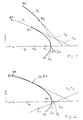
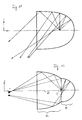
Fig.1 zeigt ein erstes Beispiel für die Konstruktion einer Reflektorform mittels eines Reflektorschnittkurve. Die Reflektorschnittkurve stellt einen Schnitt durch den Reflektor in einer Ebene dar, welche eine Achse A des Reflektors sowie eine Strahlungsquelle (nicht gezeigt) enthält. Die Strahlungsquelle ist in üblicher Weise in oder nahe einem Brennpunkt der Kegelschnitte angeordnet, welche die Reflektorschnittkurve erzeugen. In den Figuren sind verschiedene interessierende Punkte auf den gezeigten Kurven jeweils mit einem Buchstaben und einer Zahl bezeichnet. Die Zahl bedeutet jeweils die Zuordnung des Punktes zu einem bestimmten Kegelschnitt, während die Buchstaben der Unterscheidung verschiedener Punkte des Kegelschnittes dienen.1 shows a first example of the construction of a reflector shape by means of a reflector cut curve. The reflector intersection curve represents a section through the reflector in a plane which contains an axis A of the reflector and a radiation source (not shown). The radiation source is usually arranged in or near a focal point of the conic sections that generate the reflector section curve. In the figures, various points of interest on the curves shown are each identified by a letter and a number. The number means the assignment of the point to a specific conic section, while the letters serve to differentiate between different points of the conic section.
Fig.1 zeigt als Kegelschnitte zwei Parabeln P1, P2 sowie die zugehörigen Brennpunkte F1 bzw. F2. Die Scheitelpunkte S1, S2 der beiden Parabeln liegen gemeinsam auf der optischen Achse A.1 shows two parabolas P1, P2 as conic sections and the associated focal points F1 and F2. The vertices S1, S2 of the two parabolas lie together on the optical axis A.
Zunächst geht die Konstruktion der Reflektorform aus von der Parabel P1, die zweckmäßig für das zu lösende Beleuchtungsproblem ausgewählt worden ist, jedoch für sich genommen noch keine befriedigende Lichtverteilung erzeugt. Die von einer Reflektorform gemäß der Parabel P1 erzeugte Lichtverteilung zeigt an, daß besonders im äußeren Bereich (Randbereich) des Reflektors die Reflexionswinkel (entsprechend der Tangente) verändert werden sollten. Für diese Veränderung der Reflektorschnittkurve derart, daß sie außerhalb des Punktes A1 von der Parabel P1 abweicht, dient eine zweite Parabel P2. Es wird ein Punkt A1 auf der ersten Parabel P1 bestimmt, ab dem (vom Scheitel S1 aus gesehen) die Reflektorschnittkurve abgeändert werden soll. Das Stück A1 bis B2 der Parabel P1 soll also ersetzt werden durch ein anderes Kegelschnittsegment, nämlich das Segment A2 bis B2 der Parabel P2. Für diese Ersetzung werden zunächst die Tangenten T1 im Punkt A1 an der Parabel P1 und T2 im Punkt A2 an der Parabel P2 bestimmt. Die Tangenten T1, T2 schneiden die Achse A jeweils unter einem bestimmten Winkel. Zunächst werden die Tangenten in Parallellage gebracht. Hierzu wird das Segment A2-B2 der Parabel P2 um den Punkt A2 gedreht, bis die Tangente T2 parallel läuft zur Tangente T1. Sodann wird das Segment A2-B2 so parallel verschoben, daß der Punkt A2 mit dem Punkt A1 zusammenfällt. Dies ist in Fig.2 gezeigt. Die jeweils mit durchgezogener Linie dargestellten Segmente S1-A1 und A2-B2 liegen nun direkt aneinander, d.h. es gibt kein Übergangsstück zwischen den Kegelschnittsegmenten. Es entsteht eine Reflektorschnittkurve S1-A1/A2-B2 (in Fig.2 mit durchgezogener Linie dargestellt), die lückenlos aus Kegelschnittsegmenten von unterschiedlichen Kegelschnitten stammen und die stetig differenzierbar ineinander übergehen, d.h. an der Berührungsstelle A1, A2 sind die von beiden Richtungen her anlegbaren Tangenten gleich. Die Strahlungsverteilung eines gemäß der Reflektorschnittkurve von Fig.2 gebildeten Reflektors läßt sich vollständig bestimmen, da für jeden Punkt der Reflektoroberfläche die Tangente und somit Einfalls- und Ausfallswinkel eines Strahls bekannt sind.First of all, the construction of the reflector shape is based on the parabola P1, which has been selected appropriately for the lighting problem to be solved, but in itself none produces satisfactory light distribution. The light distribution generated by a reflector shape in accordance with parabola P1 indicates that the reflection angles (corresponding to the tangent) should be changed, particularly in the outer region (edge region) of the reflector. A second parabola P2 is used for this change in the reflector intersection curve in such a way that it deviates from the parabola P1 outside the point A1. A point A1 on the first parabola P1 is determined, from which (viewed from apex S1) the reflector intersection curve is to be modified. The piece A1 to B2 of the parabola P1 should therefore be replaced by another conic section, namely the segment A2 to B2 of the parabola P2. For this replacement, the tangents T1 at point A1 at parabola P1 and T2 at point A2 at parabola P2 are determined. The tangents T1, T2 each intersect the axis A at a certain angle. First, the tangents are brought into parallel position. To do this, segment A2-B2 of parabola P2 is rotated around point A2 until tangent T2 runs parallel to tangent T1. Then segment A2-B2 is shifted in parallel so that point A2 coincides with point A1. This is shown in Fig.2. The segments S1-A1 and A2-B2, each shown with a solid line, are now directly adjacent to one another, ie there is no transition piece between the conic sections. The result is a reflector intersection curve S1-A1 / A2-B2 (shown in Fig. 2 with a solid line), which consist entirely of conic section segments from different conic sections and which continuously merge into one another, i.e. at the contact point A1, A2 are from both directions equal tangents. The radiation distribution of a reflector formed according to the reflector section curve of FIG. 2 can be determined completely, since the tangent and thus the angle of incidence and angle of incidence of a beam are known for each point on the reflector surface.
Bei der in Fig.2 dargestellten Reflektorform kann vom Brennpunkt F1 abgestrahlte Strahlung im Randbereich des Reflektors (im Vergleich mit der Parabel P1) leicht nach innen reflektiert werden, während sie im zentralen Bereich parallel zur optischen Achse A reflektiert wird. Dadurch kann die Reflektorkurve S1-A1/A2-B2 einen kleineren Lichtfleck bilden als die Reflektorkurve S1-A1-B1. Es entsteht keine starke Inhomogenität (heller Ring) im Lichtfleck.In the form of the reflector shown in FIG. 2, radiation emitted by the focal point F1 can be reflected slightly inwards in the edge region of the reflector (in comparison with the parabola P1) while being reflected in the central area parallel to the optical axis A. As a result, the reflector curve S1-A1 / A2-B2 can form a smaller light spot than the reflector curve S1-A1-B1. There is no strong inhomogeneity (light ring) in the light spot.
Fig.3 zeigt eine Abwandlung des Ausführungsbeispiels gemäß Fig.2, bei der an den Punkt A1 ein Parabelsegment A2-B2 angefügt wird, dessen Krümmungsrichtung (im Vergleich zum Beispiel gemäß Fig.2) umgekehrt ist. Der Verbindungspunkt A1-A2 ist ein Wendepunkt. Der durch die Reflektorschnittkurve S1-A1/A2-B2 gebildete Reflektor reflektiert im Randbereich einfallende Strahlung im Vergleich mit dem Beispiel gemäß Fig.2 mehr nach außen, so daß der Lichtfleck vergrößerst ist.3 shows a modification of the exemplary embodiment according to FIG. 2, in which a parabola segment A2-B2 is added to the point A1, the direction of curvature of which is reversed (in comparison to the example according to FIG. 2). The connection point A1-A2 is a turning point. The reflector formed by the reflector section curve S1-A1 / A2-B2 reflects incident radiation in the edge area more in comparison with the example according to FIG. 2, so that the light spot is enlarged.
Auch bei diesem Beispiel können die Tangenten aller beteiligten Kegelschnittkurven rechnerisch festgestellt werden, so daß die Strahlungsverteilung vorab bestimmbar ist. Mit dem gezeigten Verfahren können unterschiedliche Kegelschnittsegmente von unterschiedlichen Kegelschnittarten direkt miteinander verbunden werden. Z.B. können Segmente von Parabeln mit Segmenten von Ellipsen verbunden werden.In this example, too, the tangents of all conic section curves involved can be determined mathematically, so that the radiation distribution can be determined in advance. With the method shown, different conic section segments of different conic section types can be connected directly to one another. E.g. segments of parabolas can be connected to segments of ellipses.
Aus den derart gebildeten Reflektorschnittkurven lassen sich vollständige Reflektorformen z.B. durch Rotation um die Achse A bilden oder auch durch translatorische Verschiebung der Kurven senkrecht zur Papierebene (Rinnen-Reflektor).Complete reflector shapes, e.g. by rotating around the axis A or also by translational displacement of the curves perpendicular to the paper plane (channel reflector).
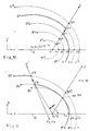
Fig.4 illustriert ein Verfahren, mit dem Reflektorschnittkurven der oben beschriebenen Art besonders einfach erzeugbar sind. Hierzu sind mehrere Parabeln P1, P2, P3, P4 und P5 so gemäß Fig.4 in bezug auf eine gemeinsame Achse A angeordnet, daß ihre Brennpunkte F1, F2, F3, F4 bzw. F5 zusammenfallen. Dieser gemeinsame Brennpunkt ist gleichzeitig der Ursprung 0 eines Polarkoordinatensystems. Fig.4 zeigt einen Strahl 0-S, der vom 0-Punkt des Polarkoordinatensystems ausgeht. Der Polarwinkel ist mit α bezeichnet. Ordnet man die Parabeln in dieser Weise an, dann schneidet der Polarstrahl 0-S die Parabeln an Punkten A1, A2, A3, A4 und A5, wobei die in diesen Punkten an die Parabeln angelegten Tangenten alle parallel sind. Dies vereinfacht die Aneinanderfügung der Kegelschnittsegmente im Vergleich zum Ausführungsbeispiel gemäß den Fig.1 und 2, da keine Drehung des anzufügenden Segmentes durchgeführt zu werden braucht. Sollen z.B. die Parabelsegmente S3-A3 und A4-B4 direkt aneinandergefügt werden, dann braucht das Segment A4-B4 nur so parallelverschoben zu werden, daß der Punkt A4 auf dem Polarstrahl 0-S in den Punkt A3 überführt wird, was in Fig.4 durch einen Pfeil angedeutet ist. Am Berührungspunkt der unterschiedlichen Segmente der so gebildeten Reflektorschnittkurve, also an der Stelle A3/A4, sind die Tangenten identisch, wie gewünscht.4 illustrates a method with which reflector cut curves of the type described above can be generated particularly easily. For this purpose, several parabolas P1, P2, P3, P4 and P5 are arranged according to FIG. 4 with respect to a common axis A in such a way that their focal points F1, F2, F3, F4 and F5 coincide. This common focus is also the
Eine wie vorstehend beschrieben gebildete Reflektorschnittkurve definiert durch Rotation um die Achse A einen Reflektor (oder durch Parallelverschiebung einen Rinnen-Reflektor), der sich von einem Paraboloid-Reflektor gemäß der Schnittkurve S3-A3-B3 dadurch unterscheidet, daß die Strahlung im Randbereich leicht nach außen reflektiert wird.A reflector intersection curve formed as described above defines a reflector by rotation about the axis A (or a channel reflector by parallel displacement), which differs from a paraboloid reflector in accordance with the intersection curve S3-A3-B3 in that the radiation in the edge area differs slightly is reflected outside.
Soll hingegen umgekehrt die Strahlung im Randbereich des Reflektors mehr nach innen reflektiert werden, wird analog dem vorstehend beschriebenen Ausführungsbeispiel z.B. das Kurvensegment A1-B1 (oder auch bei geringerer Betonung der Reflexion nach innen, das Segment A2-B2) entlang dem Polarstrahl 0-S so verschoben, daß der Punkt A1 auf dem Punkt A3 zu liegen kommt.Conversely, if, on the other hand, the radiation in the edge region of the reflector is to be reflected more inwards, analogously to the exemplary embodiment described above, e.g. the curve segment A1-B1 (or even with less emphasis on the reflection inwards, the segment A2-B2) along the polar beam 0-S so that the point A1 comes to lie on the point A3.
Auf diese Weise können in einfacher Weise unterschiedlichste Reflektorformen erzeugt werden, deren Lichtverteilung exakt im voraus bestimmbar ist.In this way, the most varied of reflector shapes can be produced in a simple manner, the light distribution of which can be determined precisely in advance.
Das vorstehend anhand von Parabeln beschriebene Ausführungsbeispiel läßt sich auch analog auf Kreise, die ebenfalls Kegelschnitte sind, anwenden.The exemplary embodiment described above with the aid of parabolas can also be applied analogously to circles which are also conic sections.
Fig.5 zeigt eine Anwendung des Konstruktionsprinzips bei Ellipsen als Ausgangs-Kegelschnitten.Fig. 5 shows an application of the design principle to ellipses as initial conic sections.
Die Fig.5 zeigt Ellipsen E1, E2, E3, E4 und E5, die so in bezug auf eine gemeinsame Längsachse A angeordnet sind, daß ihre ersten Brennpunkte F1, F2, F3, F4 bzw. F5 im Ursprung 0 eines Polarkoordinatensystems zusammenfallen. Ein Polarstrahl 0-S schneidet die Ellipsen an Punkten A1 bis A5 so, daß die Tangenten in diesen Punkten wieder jeweils alle parallel zueinander sind. Somit ergibt sich eine weitere Konstruktion völlig analog zum anhand der Fig.4 beschriebenen Ausführungsbeispiel, wobei anstelle der Parabelsegmente nunmehr Ellipsensegmente treten. Bei den vorstehend beschriebenen Ausführungsbeispielen gemäß den Fig.4 und 5 wurden jeweils zwei Kegelschnittsegmente direkt aneinandergefügt.5 shows ellipses E1, E2, E3, E4 and E5, which are arranged with respect to a common longitudinal axis A such that their first focal points F1, F2, F3, F4 and F5 coincide at the
Fig.6 zeigt ein Ausführungsbeispiel, bei dem eine Reflektorschnittkurve erzeugt wird, bei welcher mehr als zwei Kegelschnittsegmente direkt aneinandergefügt sind. Auch hier sind diejenigen Segmente, welche letztlich die zu erzeugende Reflektorschnittkurve bilden, mit durchgezogenen Linien dargestellt. Die Konstruktion der Reflektorschnittkurve vom Punkt S3 zu A3/A4 zu C4 entspricht derjenigen gemäß Fig.5. Ab dem Punkt C4 soll jedoch eine weitere Modifikation der Reflektorschnittkurve durch Anfügung eines weiteren Segmentes einer unterschiedlichen Ellipse, nämlich eines Segmentes C5-B5 der Ellipse E5 durchgeführt werden. Für eine direkte Anfügung des Segmentes C5-B5 an den Punkt C4 mit dem Ergebnis identischer Tangenten (stetige Differenzierbarkeit) wird wie folgt verfahren:6 shows an exemplary embodiment in which a reflector cut curve is generated in which more than two conic section segments are joined directly to one another. Here too, those segments which ultimately form the reflector cut curve to be generated are shown with solid lines. The construction of the reflector cut curve from point S3 to A3 / A4 to C4 corresponds to that according to Fig. 5. From point C4, however, a further modification of the reflector intersection curve is to be carried out by adding another segment of a different ellipse, namely a segment C5-B5 of the ellipse E5. For a direct addition of the segment C5-B5 to the point C4 with the result of identical tangents (continuous differentiability), proceed as follows:
Zunächst wird bei der Erzeugung der Reflektorschnittkurve S3-A3/A4-C4 eine Parallelverschiebung entlang dem Strahl 0-S durchgeführt, so daß die Punkte A3 und A4 zusammenfallen (entsprechend dem Beispiel von Fig.5). Dabei werden auch die Brennpunkte F4, F5 der Ellipsen aus dem zuvor gemeinsamen Brennpunkt (entsprechend dem Ursprung 0 des Polarkoordinatensystems) unter die Achse A verschoben und zwar um den Abstand zwischen den Ellipsen E4 und E5 auf dem Strahl 0-S.First, when generating the reflector intersection curve S3-A3 / A4-C4, a parallel shift is carried out along the beam 0-S, so that the points A3 and A4 coincide (corresponding to the example in FIG. 5). The focal points F4, F5 of the ellipses also become the previously common focal point (corresponding to the
Auch die Ellipse E5 wird so verlegt, daß ihr Brennpunkt F5 auf dem Brennpunkt F4 liegt. Die Verschiebung erfolgt unter Beibehaltung der Paralletität der Achsen A. Sodann wird der Strahl S' gezogen, der nicht vom Ursprung 0 des Polarkoordinatensystems ausgeht, sondern den Punkt C4 mit dem Punkt F4, F5 gemäß Fig.6 verbindet. Der so gebildete Strahl S' schneidet die Ellipse E5 im Punkt C5. Nunmehr wird das Ellipsensegment C5-B5 so parallelverschoben, daß der Punkt C5 auf dem Strahl S' wandert, bis er auf dem Punkt C4 zu liegen kommt. Bei dieser Konstruktion ist die gebildete Reflektorschnittkurve kantenfrei, d.h. die Tangenten im Punkt C4/C5 sind identisch. Parallelverschiebung bedeutet hier, daß die Tangentenwinkel sich nicht ändern.The ellipse E5 is also moved in such a way that its focal point F5 lies on the focal point F4. The shift takes place while maintaining the parallelism of the axes A. Then the beam S 'is drawn, which does not originate from the
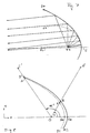
Fig.7 zeigt ein Ausführungsbeispiel, bei dem sechs Ellipsen verwendet werden, um sechs Segmente direkt kantenfrei aneinanderzufügen. Dabei ist das Parameterverhältnis b/a für alle verwendeten Ellipsen gleich, nämlich 0,87. Die Polarwinkelabstände, unter denen jeweils verschiedene Ellipsensegmente aneinandergefügt werden, betragen 20°. Die Kurvensegmente weisen mit zunehmenden Polarwinkel jeweils größere Parameter a und b auf (das Parameterverhältnis bleibt gleich, wie oben gesagt). Beim in Fig.4 gezeigten Ausführungsbeispiel wachsen die Parameter von innen nach außen (von der Achse A aus gesehen) gegenüber der ersten Ellipse der Reihenfolge nach jeweils um das 1,4-Fache, das 1,7-Fache, das 2,1-Fache, das 2,5-Fache und das 4,2-Fache. Fig.7 illustriert auch die mit einem solchen Reflektor erzeugte Strahlungsverteilung. Je näher die Strahlung am Rand (Punkt B6) des Reflektors reflektiert wird, um so weiter entfernt vom zweiten Brennpunkt F1' der ersten Ellipse E1 entfernt schneidet sie die optische Achse A. Durch diese Modifikation des Reflektors wird gegenüber einer reinen Ellipse eine homogenere Lichtverteilung erreicht.Fig. 7 shows an embodiment in which six ellipses are used to join six segments directly without edges. The parameter ratio b / a is the same for all ellipses used, namely 0.87. The polar angle distances at which different ellipse segments are joined together are 20 °. With increasing polar angle, the curve segments each have larger parameters a and b (the parameter ratio remains the same, as stated above). In the exemplary embodiment shown in FIG. 4, the parameters grow from the inside to the outside (viewed from the axis A) in relation to the first ellipse in each case by 1.4 times, 1.7 times, 2.1- Times, 2.5 times and 4.2 times. 7 also illustrates the radiation distribution generated with such a reflector. The closer the radiation is reflected at the edge (point B6) of the reflector, the further away from the second focal point F1 'of the first ellipse E1 it intersects the optical axis A. This modification of the reflector achieves a more homogeneous light distribution compared to a pure ellipse .
Es können auch mehrere Kurvensegmente in Abwandlung des Ausführungsbeispiels gemäß Fig.7 und analog dem Beispiel gemäß Fig.3 so aneinander gereiht werden, daß sich die Krümmungsrichtung ändert, d.h. die Berührungsstellen zwischen den einzelnen Segmenten sind im Sinne der Differentialrechnung Wendepunkte.It is also possible, in a modification of the embodiment according to FIG. 7 and analogously to the example according to FIG. 3, to arrange a plurality of curve segments so that the direction of curvature changes, i.e. the points of contact between the individual segments are turning points in the sense of differential calculus.
Die vorstehend beschriebenen Ausführungsbeispiele zeigen, daß die erfindungsgemäße Reflektorschnittkurve gemäß nachfolgenden Schritten erzeugt wird:
- a) Zunächst wird eine Kegelschnittkurve als Ausgangskurve ausgewählt. Dies ist z.B. die Kegelschnittkurve, welche das innere, achsnächste Segment bildet. Dieser Kegelschnitt wird nach allgemeinen Gesichtspunkten so bestimmt, daß unter den gegebenen Randbedingungen (Abmessungen, Abstände etc.) eine bestmögliche Annährung an die gewünschte Lichtverteilung gegeben ist.
- b) Für eine Vielzahl von Punkten mit gewünscht feiner Inkrementierung (Raster) der Kurve werden die Tangenten bestimmt.
- c) Für eine Vielzahl von Punkten werden Einfall- und Ausfallswinkel der Strahlung berechnet.
- d) Die auf diese Weise rein rechnerisch erzeugte Strahlungsverteilung wird dargestellt in Abhängigkeit vom Polarwinkel. Ergibt die Strahlungsverteilung, daß ab einem bestimmten Polarwinkel eine Verbesserung erreicht werden soll, so wird an dem entsprechenden Polarwinkel in der Reflektorschnittkurve ein anderes Kegelschnittsegment angesetzt und erneut die Strahlungsverteilung ermittelt. Dies kann so häufig wiederholt werden, bis die gewünschte Strahlungsverteilung mit hinreichender Güte erreicht ist.
- a) First, a conic curve is selected as the starting curve. For example, this is the conic curve, which forms the inner segment closest to the axis. This conic section is determined according to general criteria so that the best possible approximation to the desired light distribution is given under the given boundary conditions (dimensions, distances, etc.).
- b) The tangents are determined for a large number of points with the desired fine incrementation (grid) of the curve.
- c) For a large number of points, the incident and incident angles of the radiation are calculated.
- d) The radiation distribution generated in this way purely by calculation is shown as a function of the polar angle. If the radiation distribution shows that an improvement is to be achieved from a certain polar angle, a different conic section is applied to the corresponding polar angle in the reflector section curve and the radiation distribution is determined again. This can be repeated so often until the desired radiation distribution with sufficient quality is achieved.
Die Erfindung eignet sich besonders zur Anwendung auf den Fall, bei dem eine relativ langgestreckte Lichtquelle auf der optischen Achse des Reflektors angeordnet ist und mittels einer (im Stand der Technik elliptischen) Reflektorform möglichst auf einen Punkt konzentriert werden soll. Aufgrund der geometrischen Abmessungen der Lichtquelle ist dies beim Stand der Technik mit einer einfachen Ellipse nur sehr unzureichend möglich. Mit der Erfindung können eine Vielzahl von Ellipsen-Segmenten direkt kantenfrei aneinandergereiht werden, wobei die Segmente mit zunehmenden Polarwinkel so gewählt werden, daß eine stärkere Reflexion nach innen erfolgt, d.h. die Kurvensegmente weisen mit zunehmenden Polarwinkel im Vergleich mit der achsnächsten Ausgangsellipse Tangenten auf, deren Winkel mit der Achse zunehmend kleiner wird.The invention is particularly suitable for use in the case in which a relatively elongated light source is arranged on the optical axis of the reflector and is to be concentrated on one point as far as possible by means of a reflector shape (elliptical in the prior art). Due to the geometric dimensions of the light source, this is only possible to a very limited extent with a simple ellipse in the prior art. With the invention, a multiplicity of ellipse segments can be lined up directly without edges, the segments being selected with increasing polar angle in such a way that there is more internal reflection, i.e. with increasing polar angle, the curve segments have tangents in comparison with the nearest output ellipse, the angle of which becomes increasingly smaller with the axis.
Mit Hyperbel-Segmenten kann das gleiche Verfahren analog durchgeführt werden, wobei das Parameterverhältnis b/a ebenfalls konstant gehalten wird.The same procedure can be carried out analogously with hyperbolic segments, the parameter ratio b / a also being kept constant.
Das vorstehend erläuterte Verfahren zur Erzeugung von Reflektorformen läßt sich weiterentwickeln. Dies ist in Fig.8 erläutert. Die dort gezeigte Kurve R1 ist gemäß einer der Fig.1 bis 7 und der zugehörigen Beschreibung erzeugt, d.h. die Kurve R1 entspricht einer direkten Aneinanderreihung von Kegelschnittsegmenten. Diese Kurve R1 soll weiter modifiziert werden. Ein der Kurve R1 zugeordnetes Polarkoordinatensystem hat seinen Ursprung im Punkt 0. Der Polarstrahl 0-S schneidet die Kurve R1 im Punkt A unter dem Winkel α. Die neu zu bildende Reflektorschnittkurve R2 ist mit durchgezogener Linie dargestellt und wird durch ein sogenanntes Abstandsverhältnis k festgelegt. Dieses Abstandverhältnis k ist bereits in der oben genannten EP 0 402 740 A2 eingeführt und wird entsprechend auch auf die hier nachfolgend beschriebenen Ausführungsbeispiele angewandt. In Fig.8 wird das Abstandsverhältnis k wie folgt definiert.![]()
wobei 0-A der Abstand zwischenden Punkten 0 und A ist.The method for producing reflector shapes explained above can be further developed. This is explained in Fig.8. The curve R1 shown there is generated in accordance with one of FIGS. 1 to 7 and the associated description, ie the curve R1 corresponds to a direct sequence of conic section segments. This curve R1 is to be modified further. A polar coordinate system assigned to curve R1 has its origin at ![]()
where 0-A is the distance between
Die Kurve R2 ergibt sich dann dadurch, daß im Polarkoordinatensystem für jeden Punkt der Kurve R1 das Produkt aus dem Abstand 0-A mit dem Abstandsverhältnis k gebilet wird, um den entsprechenden Punkt der Kurve R2 zu erhalten. Beim Ausführungsbeispiel gemäß Fig.8 ist das Abstandsverhältnis k für jeden Punkt der Kurve größer als 1. Mit größer werdendem Polarwinkel ändert sich allerdings das Abstandsverhältnis k, es wird kleiner und nähert sich 1, wie der Kurve unmittelbar zu entnehmen ist. Somit kann das Abstandsverhältnis k als Funktion des Polarwinkels variiert werden. Solche Funktionen sind in der EP 0 402 740 A2, Sp.6, Z.51 - 54 angegeben und können hier ebenfalls angewandt werden.The curve R2 then results from the fact that in the polar coordinate system the product from the distance 0-A is formed with the distance ratio k for each point of the curve R1 in order to obtain the corresponding point of the curve R2. In the exemplary embodiment according to FIG. 8, the distance ratio k is greater than 1 for each point on the curve. However, as the polar angle increases, the distance ratio k changes, it becomes smaller and approaches 1, as can be seen directly from the curve. The distance ratio k can thus be varied as a function of the polar angle. Such functions are specified in
Das Abstandsverhältnis k kann auch kleiner als 1 werden. Dabei würde dann in Abwandlung des Ausführungsbeispiels gemäß Fig.8 die äußere Kurve R2 unter die innere Kurve R1 laufen.The distance ratio k can also be less than 1. 8, the outer curve R2 would then run under the inner curve R1.
Eine so erzeugte Reflektorschnittkurve R2 entspricht keiner Kegelschnittkurve. Die Kurven lassen sich auch nicht in einer analytischen Form ausdrücken (keine Formel). Gleichwohl können Tangenten für jeden Punkt der Kurve R2 gebildet werden. Für die Kurve R1 sind nämlich Tangenten bekannt, wie oben dargestellt ist, weil es sich jeweils um Kegelschnittsegmente handelt. Andererseits ist auch das Abstandsverhältnis k als Funktion des Polarwinkels α bekannt. Somit kann, ausgehend von der Tangente an einem beliebigen Punkt A der Kurve R1, auch der Tangentenwinkel am auf dem Polarstrahl 0-S zugeordneten Punkt B der Reflektorschnittkurve R2 bestimmt werden. Es genügt hierfür, jeweils einen Differenzen-Quotienten zu bilden, der hinreichend nahe am untersuchten Punkt liegt, um eine gewünschte Annäherung an den exakten Differentialquotienten zu erreichen.A reflector section curve R2 generated in this way does not correspond to a cone section curve. The curves cannot be expressed in an analytical form either (no formula). Nevertheless, tangents can be formed for every point on curve R2. Tangents are known for curve R1, as shown above, because they are each conic section segments. On the other hand, the distance ratio k as a function of the polar angle α is also known. Thus, starting from the tangent at any point A of curve R1, the tangent angle at point B of the reflector section curve R2 assigned on the polar beam 0-S can also be determined. To do this, it is sufficient to form a difference quotient that is sufficiently close to the point under investigation to achieve a desired approximation to the exact differential quotient.
Fig.9 zeigt die Strahlungsverteilung eines Reflektors, der durch Rotation um die Achse A mittels der Reflektorschnittkurve R2 erzeugt ist. Ein Vergleich mit Fig.7 ergibt, daß die Lichtverteilung auf einem senkrecht zur Achse A stehenden, unter Abstand angeordneten Schirm breiter ist.FIG. 9 shows the radiation distribution of a reflector which is generated by rotation about the axis A by means of the reflector section curve R2. A comparison with FIG. 7 shows that the light distribution is wider on a screen arranged perpendicular to the axis A and at a distance.
Fig.10 zeigt eine Abwandlung des Ausführungsbeispiels gemäß Fig.8. Eine der oder beide Kurven R1 und R2 gemäß Fig.10 sind durch ein Verfahren gemäß den Fig.1 bis 7 und der zugehörigen Beschreibung gebildet. Falls nur eine der beiden Kurven so erzeugt ist, kann es sich bei der anderen Kurve um einen herkömlichen Kegelschnitt handeln. Der Schnittpunkt C der neu zu erzeugenden Reflektorschnittkurve R wird durch ein Abstandsverhältnis k festgelegt. Das Abstandsverhältnis k wird wie folgt definiert:![]()
![]()
Wenn k = 1 gewählt wird, fällt die Reflektorkurve R mit der nebenliegenden Kurve und bei k = 0 mit der anderen nebenliegenden Kurve zusammen. Üblicherweise liegt k zwischen 0 und 1, es kann aber auch > 1 und < 0 werden.If k = 1 is selected, the reflector curve R coincides with the adjacent curve and at k = 0 with the other adjacent curve. Usually k is between 0 and 1, but it can also be> 1 and <0.
Weiterhin kann das Abstandsverhältnis als Funktion des Polarwinkels α variieren oder konstant sein.Furthermore, the distance ratio can vary as a function of the polar angle α or be constant.
Beim Ausführungsbeispiel gemäß Fig.10 ist k konstant gewählt, die Kurve R2 ist eine Parabel und die Kurve R1 ist eine Zusammenfügung von mehreren Ellipsensegmenten, deren Tangentenwinkel mit größer werdendem Polarwinkel immer kleiner werden im Vergleich zur achsnahen Ausgangsellipse. Mit dieser Reflektorform kann eine absolut homogene Lichtverteilung erzeugt werden.In the exemplary embodiment according to FIG. 10, k is chosen to be constant, curve R2 is a parabola and curve R1 is a combination of several ellipse segments whose tangent angles become smaller and smaller as the polar angle increases compared to the axis ellipse close to the axis. With this reflector shape, an absolutely homogeneous light distribution can be generated.
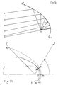
Fig.11 zeigt ein anderes Ausführungsbeispiel einer erfindungsgemäß erzeugten Reflektorform. Der Reflektor hat eine glockenähnliche Gestalt. Diese Form ermöglicht eine sogenannte "batwing"(flügelförmige)-Lichtverteilung, wobei die sogenannte Direktblendung weitgehend reduziert ist. Eine solche Reflektorform kann besonders bei einer Verkaufsraumbeleuchtung Anwendung finden. Bei der Beleuchtung von Verkaufsräumen ist es wichtig, eine hinreichende vertikale Lichtverteilung zu erzeugen, dies gilt insbesondere für Bekleidungsgeschäfte, bei denen eine horizontale Lichtverteilung unerwünscht ist. Weiterhin soll ein Reflektor für diesen Einsatzzweck relativ lang sein, um eine Direktblendung durch die Lichtquelle zu vermeiden.11 shows another exemplary embodiment of a reflector shape produced according to the invention. The reflector has a bell-like shape. This shape enables a so-called "batwing" (wing-shaped) light distribution, the so-called direct glare being largely reduced. Such a reflector shape can be used particularly in retail lighting. When illuminating sales rooms, it is important to generate a sufficient vertical light distribution, this is particularly true for clothing stores where horizontal light distribution is undesirable. Furthermore, a reflector for this purpose should be relatively long in order to avoid direct glare from the light source.
Mit dem Stand der Technik ist es schwierig, diese beiden Anforderungen gleichzeitig zu erfüllen, da ein langer ellipsenförmiger Reflektor keine flügelförmige, sondern eine torpedoförmige Lichtverteilung erzeugt.With the prior art, it is difficult to meet these two requirements at the same time, since a long elliptical reflector produces a torpedo-shaped light distribution rather than a wing-shaped one.
Im Stand der Technik werden deshalb unterschiedliche Kurven miteinander verbunden, wie in Fig.12 gezeigt ist. Für die Frontseite F des Reflektors wird eine Ellipse verwendet. Die Lichtquelle ist mit 0 bezeichnet. Im hinteren Bereich H des Reflektors wird ein kreisabschnittförmiger Reflektor verwendet oder eine Ellipse, die nahezu kreisförmig ist. Hierdurch wird die Strahlung von der Lichtquelle in diesem Bereich zur Frontseite F reflektiert und dann mit einem größeren Ausfallwinkel nach außen weiterreflektiert.Different curves are therefore connected to one another in the prior art, as shown in FIG. An ellipse is used for the front F of the reflector. The light source is labeled 0. In the rear area H of the reflector, a circular segment-shaped reflector or an ellipse that is almost circular is used. As a result, the radiation is reflected from the light source in this area to the front side F and then further reflected to the outside with a larger angle of reflection.
Bei dieser Lösung werden zwei Kurven kantig miteinander verbunden, so daß ein dunkler Ring im Lichtfleck entsteht. Da etwa eine Hälfte der Strahlen zweimal reflektiert wird, ist ein Verlust unvermeidlich. Außerdem kann dieser Reflektor keine breite, flügelförmige Lichtverteilung erzeugen. Um den dunklen Ring verschwinden zu lassen und um eine breitere Lichtverteilung zu erreichen, wird die Reflexionsoberfläche grob bearbeitet, wie durch Hammerschlag oder Sandstrahlung. Dadurch nimmt aber der Strahlungsverlust deutlich zu. Das Streulicht kann eine Direktblendung beim Beobachter erzeugen.With this solution, two curves are connected to each other so that a dark ring is created in the light spot. Since about half of the rays are reflected twice, loss is inevitable. In addition, this reflector cannot produce a broad, wing-shaped light distribution. In order to make the dark ring disappear and to achieve a broader light distribution, the reflection surface is roughly processed, like by hammer blow or sandblasting. As a result, the radiation loss increases significantly. The scattered light can cause direct glare to the observer.
Die erfindungsgemäß erzeugte glockenförmige Reflektorgestalt gemäß Fig.11 bewirkt demgegenüber eine einzige Strahlungsreflexion und erzeugt eine sehr breite Lichtverteilung. Es entsteht kein dunkler Ring im Lichtfleck, da die Kurve kantenfrei ist.By contrast, the bell-shaped reflector shape according to FIG. 11 produced according to the invention brings about a single radiation reflection and produces a very wide light distribution. There is no dark ring in the light spot since the curve is free of edges.
Ein weiterer Vorteil besteht darin, daß sich bei der erfindungsgemäßen glockenförmigen Reflektorform eine einfache Veränderung der Lichtverteilung erreichen läßt durch Verschieben der Lichtquelle auf der Achse. Dabei ist die Lichtverteilung immer flügelförmig (vgl. Punkte 0 und 0' gemäß Fig.13). Wesentlich ist, daß bei diesem Reflektor der Schulterbereich (Fig.13, SCH) die Strahlung am breitesten und sehr intensiv reflektiert (vgl. Fig.11). Da der Schulterbereich nur eine geringe Distanz von der Lichtquelle 0 hat, kann durch eine geringfügige Verschiebung 0-0' auf der Achse der Einfallswinkel stark geändert werden (vgl. Fig.13). Dabei erzeugt aber der Schulterbereich trotz der Verschiebung der Lichtquelle immer eine breite und intensive Strahlung, so daß die Lichtverteilung insgesamt flügelförmig bleibt.Another advantage is that in the bell-shaped reflector shape according to the invention, a simple change in the light distribution can be achieved by moving the light source on the axis. The light distribution is always wing-shaped (see
Ein weiterer Vorteil dieses Reflektors besteht darin, daß eine Direktblendung für einen von der Leuchte weit entfernten Beobachter trotz des großen Ausstrahlungswinkels nicht auftritt, weil die Strahlung mit dem größten Ausfallwinkel (in bezug auf die optische Achse) vom Schulterbereich her reflektiert wird, also indirekt ist.Another advantage of this reflector is that, despite the large beam angle, direct glare does not occur for an observer far away from the lamp, because the radiation with the largest angle of reflection (with respect to the optical axis) is reflected from the shoulder area, i.e. is indirect .
Wird dieser Reflektor relativ groß gestaltet, kann der Scheitelbereich mit einer groben Oberfläche versehen werden, um eine zu große Lichtintensität in der Mitte des Lichtfleckes zu vermeiden.If this reflector is made relatively large, the apex area can be provided with a coarse surface in order to avoid excessive light intensity in the center of the light spot.
Eine derartige glockenförmige Kurve kann mit dem erfindungsgemäßen Verfahren hergestellt werden, wenn die Parameter der Kurven wie folgt festgelegt werden, vgl. Fig.14:
- Zunächst werden eine Parabel und eine Ellipse ausgewählt. Dabei soll die Ellipse so große Parameter haben, daß ihre Kurve im Scheitelbereich S zumindest annähernd so steil ist wie die Kurve der Parabel. Der Einfachheit halber können die beiden Scheitel zusammenfallen. Das Abstandsverhältnis k ist konstant und wird ziemlich klein gewählt, wenn l = A - c definiert ist.
- Nach einem kurzen Stück mit steiler Steigung wird die Kurve der ersten Ellipse fortgeführt durch ein Kurvensegment einer anderen Ellipse, die wesentlich kleinere Parameter aufweist. Dieses weitere Kurvensegment verläuft nur über ein relativ kurzes Stück, z.B. 2 bis 10° im Polarkoordinatensystem.
- Sodann wird ein weiteres Ellipsensegment angesetzt, wobei die Parameter dieser Ellipse mittlere Werte sind.
- Nach dem Schulterbereich werden die Parameter der für die Kurvensegmente herangezogenen Ellipsen und Parabeln so ausgewählt, daß die Tangenten mit zunehmenden Polarwinkel des Reflektors allmählich parallel zur Achse laufen.
- First a parabola and an ellipse are selected. The ellipse should have such large parameters that its curve in the apex region S is at least approximately as steep as the curve of the parabola. For the sake of simplicity, the two vertices can coincide. The distance ratio k is constant and is chosen to be quite small if l = A - c is defined.
- After a short stretch with a steep slope, the curve of the first ellipse is continued by a curve segment of another ellipse that has significantly smaller parameters. This further curve segment runs only over a relatively short distance, for example 2 to 10 ° in the polar coordinate system.
- A further ellipse segment is then set up, the parameters of this ellipse being mean values.
- After the shoulder area, the parameters of the ellipses and parabolas used for the curve segments are selected so that the tangents gradually run parallel to the axis with increasing polar angle of the reflector.
Die in erfindungsgemäßer Weise hergestellten Reflektorschnittkurven können sowohl für rotationssymmetrische Reflektoren als auch für rinnenförmige Reflektoren verwendet werden.The reflector cut curves produced in the manner according to the invention can be used both for rotationally symmetrical reflectors and for channel-shaped reflectors.
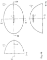
Weiterhin kann die Erfindung auch eingesetzt werden bei Reflektoren, die nicht rotationssymmetrisch oder rinnenförmig sind, wie in Fig.15 dargestellt ist. Fig.15 zeigt ein Beispiel eines solchen Reflektors, bei dem der Querschnitt senkrecht zur optischen Achse A oval ist. Fig.15a zeigt einen Vertikalschnitt entlang der Linie I-I von Fig.15b, welche eine Draufsicht auf den Reflektor (aus der Beleuchtungsrichtung) zeigt. Fig.15c zeigt einen Schnitt entlang der Linie II-II von Fig.15b. Ein solcher Reflektor eignet sich besonders für den Einsatz einer langgestreckten Lichtquelle L. Wie den Fig.15a - c zu entnehmen ist, steht die Längsachse der Lichtquelle L senkrecht zur optischen Achse A des Reflektors. Trotz dieser langgestreckten Form der Lichtquelle kann mit dem Reflektor ein etwa kreisförmiger Lichtfleck erzeugt werden, da die Strahlen, welche von den Enden der Lichtquelle ausgehen, wegen des ovalen Querschnittes zum größten Teil nach innen reflektiert werden.Furthermore, the invention can also be used for reflectors that are not rotationally symmetrical or channel-shaped, as shown in FIG. 15. 15 shows an example of such a reflector, in which the cross section perpendicular to the optical axis A is oval. 15a shows a vertical section along the line II of Fig.15b, which shows a plan view of the reflector (from the direction of illumination). Fig.15c shows a section along the line II-II of Fig.15b. Such a reflector is particularly suitable for the use of an elongated light source L. As can be seen in FIGS. 15a-c, the longitudinal axis of the light source L is perpendicular to the optical axis A of the reflector. Despite this elongated shape of the light source, an approximately circular light spot can be generated with the reflector, since the rays emanating from the ends of the light source are largely reflected inward because of the oval cross section.
Ein solcher Reflektor kann erfindungsgemäß so gebildet werden, daß die Schnittkurven gemäß den Fig.15a und 15c erfindungsgemäß (siehe oben) gebildet werden. Die Reflektorschnittkurven in Ebenen senkrecht zur optischen Achse (Fig.15b) werden so festgelegt, daß sie ellipsenförmig sind, wobei die Parameter (große und kleine Achse) den entsprechenden Abmessungen von Fig.15a bzw. 15c entsprechen.Such a reflector can be formed according to the invention in such a way that the cutting curves according to FIGS. 15a and 15c are formed according to the invention (see above). The reflector intersection curves in planes perpendicular to the optical axis (FIG. 15b) are determined in such a way that they are elliptical, the parameters (large and small axes) corresponding to the corresponding dimensions of FIGS. 15a and 15c.
In Abwandlung des vorstehend beschriebenen Ausführungsbeispiels kann ein Reflektor entsprechend Fig.15 auch so erzeugt werden, daß diejenigen Reflektorschnittkurven, die in Ebenen liegen, welche die optische Achse enthalten (also gemäß Fig.15a und 15c) wiederum erfindungsgemäß gebildet sind, während diejenigen Reflektorschnittkurven, welche in Ebenen senkrecht zur optischen Achse liegen (Fig.15b) mittels Ellipsen festgelegt werden, deren Parameter frei gewählt werden.In a modification of the exemplary embodiment described above, a reflector according to FIG. 15 can also be produced in such a way that those reflector intersection curves which lie in planes which contain the optical axis (that is to say according to FIGS. 15a and 15c) are again formed according to the invention, while those reflector intersection curves, which lie in planes perpendicular to the optical axis (Fig.15b) are determined by means of ellipses, the parameters of which can be freely selected.
Claims (15)
- A reflector for radiation which emanates from a radiation source, having such configuration that a reflector intersection curve in a plane containing an axis (A) of the reflector as well as the radiation source comprises segments (S1-A1, A2-B2) of various curved conic sections merging without edges, the conic segments (S1-A1, A2-B2) being joined directly to each other, characterized in that, at the point of contact (A1, A2) of two joined conic segments (S1-A1, A2-B2), the tangents (T1, T2) which can be put to the two conic segments are the same, and that the first foci (F1, F2) of the conic segments (S1-A1, A2-B2) diverge.
- The reflector as claimed in claim 1, characterized in that the various conics are of the same type of conic section.
- The reflector as claimed in claim 1, characterized in that the various conics are of different types of conic section.
- The reflector as claimed in claim 1, characterized in that at least two segments of the reflector inersection curve are parabolic and the foci and the X-axes (A) of the corresponding parabolas coincide, the joining of two segments (S1-A1, A2-B2) being such that the angles (α) defined by the points of contact (A3, A4) of the segments (S3-A3, A4-B4) and their X-axes (A) are the same, and that one of the segments is moved, without rotation, with its end point (A4) along a polar ray (S) corresponding to this polar angle (α) until this end point (A4) coincides with an end point (A3) of the other segment (S3-A3).
- The reflector as claimed in any one of the preceding claims, characterized in that the reflector intersection curve is composed of more than two segments of different conic sections.
- The reflector as claimed in claim 1, characterized in that the conic sections are elliptical, the axial ratio (a/b) of the ellipses being constant.
- The reflector as claimed in claim 5 or 6, characterized in that the conic sections have increasing parameters as the polar angle increases.
- The reflector as claimed in claim 5, characterized in that, as the polar angle (α) increases, the tangents which can be put to the reflector intersection curve enclose a smaller angle with the axis (A) of the reflector than those tangents which can be put to the conic of the first segment which is closest to the axis.
- A reflector for radiation which emanates from a radiation source, having such configuration that a reflector intersection curve (R2 in fig. 8; R in fig. 10) in a plane containing an axis (x) of the reflector as well as the radiation source is formed by multiplication of a reflector intersection curve (R1 in fig. 8; R1, R2 in Fig. 10) of a reflector, as claimed in any one of claims 1 to 8, with a distance ratio (k), the distance ratio (k)
either (fig. 8) being defined as the ratio (O-B/O-A) of the distance (O-B)
between the origin (O) of a polar ray and its point of intersection (B in fig. 8) with the reflector intersection curve first mentioned (R2 in fig. 8)
and the distance (O-A)
between the origin (O) of the polar ray and its point of intersection (A in fig. 8) with the reflector intersection curve mentioned secondly (R1 in fig. 8),
or (fig. 10) being defined as the ratio (l/L) of the distance (l)
between the point of intersection (C in fig. 10) of a polar ray with the reflector intersection curve first mentioned (R in fig. 10)
and the point of intersection (A or B in fig. 10) of the polar ray with the reflector intersection curve mentioned secondly or another curve (R1 or R2 in fig. 10)
and the distance (L)
between the points of intersection (A and B in fig. 10) of the polar ray with the reflector intersection curve mentioned secondly and the other curve (R1 and R2 in fig. 10). - A method of producing a reflector configuration whose intersection curve in a plane containing an axis (A) of the reflector comprises segments (S1-A1, A2-B2) of various, curved conic sections merging without edges, characterized in that the conic segments (S1-A1, A2-B2) are joined directly to each other such that, at their point of contact (A1, A2), the tangents (T1, T2) which can be put to the two conic segments coincide, and in that the first foci (F1, F2) of the conic segments (S1-A1, A2-B2) diverge.
- The method as claimed in claim 10, characterized in that the joining of the conic segments is effected by translatory movement of one segment along a polar ray (S) (figs. 4, 5).
- The method as claimed in claim 10, characterized in that the joining of the conic segments is effected by rotating one segment until a tangent (T2) to one of its end points (A2) becomes parallel to a tangent (T1) to an end point (A1) of the other segment, and dispacing one of the end points mentioned (figs. 1, 2).
- A method of producing a reflector configuration, characterized in that a starting intersection curve is made of conic segments as defined in any one of claims 10 to 12, and in that this starting intersection curve is extended and/or compressed by a distance factor (k) so as to obtain an intersection curve in a plane which contains an axis of the reflector.
- The reflector as claimed in any one of claims 1 to 9 for wing-shaped distribution of radiation, characterized in that the reflector has the shape of a bell.
- The reflector as claimed in any one of claims 1 to 9 or claim 14, comprising a relatively long radiation source, disposed transversely of the optical axis, to generate a circular light spot, characterized in that the cross section of the reflector which intersects the optical axis is oval.
Priority Applications (4)
| Application Number | Priority Date | Filing Date | Title |
|---|---|---|---|
| DE59107556T DE59107556D1 (en) | 1991-06-21 | 1991-06-21 | Reflector and method for producing a reflector shape |
| EP91110286A EP0519112B1 (en) | 1991-06-21 | 1991-06-21 | Reflector and method of generating a reflector shape |
| US07/896,194 US5408363A (en) | 1991-06-21 | 1992-06-10 | Reflector and a method of generating a reflector shape |
| JP4161037A JPH0793045B2 (en) | 1991-06-21 | 1992-06-19 | Method for designing reflector and cross-section curve for reflector |
Applications Claiming Priority (1)
| Application Number | Priority Date | Filing Date | Title |
|---|---|---|---|
| EP91110286A EP0519112B1 (en) | 1991-06-21 | 1991-06-21 | Reflector and method of generating a reflector shape |
Publications (2)
| Publication Number | Publication Date |
|---|---|
| EP0519112A1 EP0519112A1 (en) | 1992-12-23 |
| EP0519112B1 true EP0519112B1 (en) | 1996-03-13 |
Family
ID=8206862
Family Applications (1)
| Application Number | Title | Priority Date | Filing Date |
|---|---|---|---|
| EP91110286A Expired - Lifetime EP0519112B1 (en) | 1991-06-21 | 1991-06-21 | Reflector and method of generating a reflector shape |
Country Status (4)
| Country | Link |
|---|---|
| US (1) | US5408363A (en) |
| EP (1) | EP0519112B1 (en) |
| JP (1) | JPH0793045B2 (en) |
| DE (1) | DE59107556D1 (en) |
Families Citing this family (35)
| Publication number | Priority date | Publication date | Assignee | Title |
|---|---|---|---|---|
| CN1083080C (en) | 1994-03-10 | 2002-04-17 | 皇家菲利浦电子有限公司 | Electric reflector lamp |
| JP3185125B2 (en) * | 1994-10-28 | 2001-07-09 | 株式会社小糸製作所 | Reflector of vehicle lamp and method of forming the same |
| JP3185126B2 (en) * | 1994-10-28 | 2001-07-09 | 株式会社小糸製作所 | Reflector of vehicle lamp and method of forming the same |
| JP3187293B2 (en) * | 1995-07-17 | 2001-07-11 | 株式会社小糸製作所 | Method for forming a reflecting surface of a reflector of a vehicle lamp |
| WO1997018551A1 (en) * | 1995-11-15 | 1997-05-22 | Universidad Nacional Autonoma De Mexico | Compound multifocal reflectors for concentrating shock waves |
| US5934779A (en) * | 1996-07-26 | 1999-08-10 | Eastman Kodak Company | Reflector and a reflector/light source system |
| US5961196A (en) * | 1996-07-26 | 1999-10-05 | Eastman Kodak Company | Flash device for dye transferring |
| US6007220A (en) * | 1996-11-13 | 1999-12-28 | Innovative Engineering Solutions, Inc | Reflectors for fluorescent light fixtures |
| ITTO970059A1 (en) * | 1997-01-27 | 1998-07-27 | Fiat Ricerche | REFLECTOR FOR LIGHTING DEVICE WITH LUMINOUS SOURCE ESTE SA. |
| JPH10268449A (en) * | 1997-03-24 | 1998-10-09 | Fuji Photo Optical Co Ltd | Illuminating optical system and projection optical system using the same |
| US5913599A (en) * | 1997-06-11 | 1999-06-22 | Steris Corporation | Surgical light with conical reflector |
| JP4011221B2 (en) * | 1999-01-21 | 2007-11-21 | 株式会社小糸製作所 | Vehicle sign light |
| JP3424915B2 (en) * | 1999-04-06 | 2003-07-07 | スタンレー電気株式会社 | Method of manufacturing reflector and lamp |
| DE19940207B4 (en) * | 1999-08-25 | 2005-07-14 | Tetsuhiro Kano | Reflector system for guiding light at small angles of incidence |
| JP4563557B2 (en) * | 2000-07-18 | 2010-10-13 | 株式会社トプコン | Illumination optical system of exposure equipment |
| USD438135S1 (en) | 2000-07-28 | 2001-02-27 | Accu-Sort Systems, Inc. | Varying elliptical reflector |
| US6967283B2 (en) | 2001-03-20 | 2005-11-22 | American Power Conversion Corporation | Adjustable scalable rack power system and method |
| US6705737B1 (en) * | 2002-08-20 | 2004-03-16 | Raytheon Co. | Reflective optical apparatus for interconverting between a point of light and a line of light |
| US7034320B2 (en) * | 2003-03-20 | 2006-04-25 | Intel Corporation | Dual hemispherical collectors |
| ATE514898T1 (en) * | 2004-03-30 | 2011-07-15 | Illumination Man Solutions Inc | APPARATUS AND METHOD FOR IMPROVED LIGHTING AREA FILLING |
| US20080030982A1 (en) * | 2006-08-04 | 2008-02-07 | Vode Llc | Modular lighting system |
| DE102009013812A1 (en) | 2009-03-18 | 2010-09-23 | Osram Gesellschaft mit beschränkter Haftung | Reflector, light source arrangement and projector device |
| US8556813B2 (en) | 2009-07-08 | 2013-10-15 | Sanuwave, Inc. | Extracorporeal pressure shock wave device |
| CN101900296B (en) * | 2010-08-30 | 2012-06-27 | 珠海晟源同泰电子有限公司 | Method for designing dodging and beaming reflector |
| US9791690B2 (en) | 2012-05-29 | 2017-10-17 | Siemens Healthcare Diagnostics Inc. | Shutter assembly for a luminescence-based sample analyzer |
| WO2014152845A1 (en) | 2013-03-20 | 2014-09-25 | Siemens Healthcare Diagnostics Inc. | Light and shutter for a sample analyzer |
| CN105526557A (en) * | 2014-10-23 | 2016-04-27 | 北京航天长征飞行器研究所 | A Condenser for Xenon Lamp with Inverted Anode |
| DE102014117453A1 (en) * | 2014-11-27 | 2016-06-02 | Carl Zeiss Smt Gmbh | Collector mirror for microlithography |
| US10808896B2 (en) * | 2014-12-31 | 2020-10-20 | Aron Lighting LLC | T-bar lighting assembly |
| CA3050008A1 (en) | 2017-01-17 | 2018-07-26 | Soliton, Inc. | Rapid pulse electrohydraulic (eh) shockwave generator apparatus with improved acoustic wavefronts |
| US10859242B2 (en) | 2018-02-07 | 2020-12-08 | Aron Lighting LLC | Downlight for ceiling system |
| USD921266S1 (en) | 2018-11-16 | 2021-06-01 | Aron Lighting LLC | Lighting fixture in a ceiling tile arrangement |
| US11543092B2 (en) | 2020-06-08 | 2023-01-03 | Aron Lighting LLC | Ceiling mounted assembly for electrical components |
| CN114966706B (en) * | 2022-04-14 | 2022-12-20 | 西安定华电子股份有限公司 | Determining method, determining system, reflector, vertical tank external liquid level meter and mounting method thereof |
| DE102022211866A1 (en) * | 2022-11-09 | 2024-05-16 | Carl Zeiss Smt Gmbh | Mirror element, lithography system and method for providing a mirror element |
Citations (1)
| Publication number | Priority date | Publication date | Assignee | Title |
|---|---|---|---|---|
| EP0307657A2 (en) * | 1987-09-17 | 1989-03-22 | Robert Bosch Gmbh | Motor vehicle headlight |
Family Cites Families (19)
| Publication number | Priority date | Publication date | Assignee | Title |
|---|---|---|---|---|
| DE159809C (en) * | ||||
| US2759106A (en) * | 1951-05-25 | 1956-08-14 | Wolter Hans | Optical image-forming mirror system providing for grazing incidence of rays |
| US2819404A (en) * | 1951-05-25 | 1958-01-07 | Herrnring Gunther | Optical image-forming mirror systems having aspherical reflecting surfaces |
| US3443086A (en) * | 1967-05-16 | 1969-05-06 | Giannini Scient Corp | Beam-forming system |
| CH526071A (en) * | 1968-08-21 | 1972-07-31 | Leon Perret Samuel | Radiation projection and reception reflector |
| GB2079435B (en) * | 1980-07-03 | 1984-05-23 | Gen Electric | Reflector lamp |
| DD159809A1 (en) * | 1981-06-19 | 1983-04-06 | Reinhard Goerke | LIGHT WITH ASYMMETRIC REFLECTOR |
| NL8105535A (en) * | 1981-12-09 | 1983-07-01 | Philips Nv | REFLEKTOR. |
| JPS5940403A (en) * | 1982-08-27 | 1984-03-06 | 三菱電機株式会社 | floodlight |
| US4557569A (en) * | 1983-11-17 | 1985-12-10 | The United States Of America As Represented By The Secretary Of The Army | Distended point source reflector having conical sections |
| JPS60184250A (en) * | 1984-03-01 | 1985-09-19 | フュージョン・システムズ・コーポレーション | Lamp having segmented reflector |
| JP2622564B2 (en) * | 1986-12-30 | 1997-06-18 | ヴァレオ ヴイジョン | Automotive headlamp with deformed bottom that emits a beam defined by a cut-off |
| FR2623633B1 (en) * | 1987-11-25 | 1991-08-16 | Armines | INFRARED RADIATION TRANSMITTING APPARATUS COMPRISING AT LEAST ONE CYLINDRICAL SOURCE OF INFRARED RADIATION AND A REFLECTOR |
| DE68917198T2 (en) * | 1988-05-09 | 1994-11-17 | Ichiko Industries Ltd | Headlights for motor vehicles. |
| FR2634003B1 (en) * | 1988-07-05 | 1991-05-24 | Cibie Projecteurs | MOTOR VEHICLE PROJECTOR WITH MULTI-ZONE REFLECTOR AND METHOD FOR SMOOTHING SUCH A REFLECTOR |
| JP2508827B2 (en) * | 1988-11-30 | 1996-06-19 | 市光工業株式会社 | Automotive headlights |
| JPH0810561B2 (en) * | 1988-11-30 | 1996-01-31 | 市光工業株式会社 | Headlight optics |
| DE3919334A1 (en) * | 1989-06-13 | 1990-12-20 | Tetsuhiro Kano | REFLECTOR FOR A LAMP |
| US4984140A (en) * | 1989-07-19 | 1991-01-08 | Ellion M Edmund | Hand held flashlight with selective beam and enhanced apparent brightness |
-
1991
- 1991-06-21 EP EP91110286A patent/EP0519112B1/en not_active Expired - Lifetime
- 1991-06-21 DE DE59107556T patent/DE59107556D1/en not_active Expired - Lifetime
-
1992
- 1992-06-10 US US07/896,194 patent/US5408363A/en not_active Expired - Fee Related
- 1992-06-19 JP JP4161037A patent/JPH0793045B2/en not_active Expired - Fee Related
Patent Citations (1)
| Publication number | Priority date | Publication date | Assignee | Title |
|---|---|---|---|---|
| EP0307657A2 (en) * | 1987-09-17 | 1989-03-22 | Robert Bosch Gmbh | Motor vehicle headlight |
Also Published As
| Publication number | Publication date |
|---|---|
| JPH0793045B2 (en) | 1995-10-09 |
| JPH06119805A (en) | 1994-04-28 |
| DE59107556D1 (en) | 1996-04-18 |
| US5408363A (en) | 1995-04-18 |
| EP0519112A1 (en) | 1992-12-23 |
Similar Documents
| Publication | Publication Date | Title |
|---|---|---|
| EP0519112B1 (en) | Reflector and method of generating a reflector shape | |
| DE3027719C2 (en) | ||
| EP0402740B2 (en) | Method to determine the shape of a reflector | |
| DE3024040C2 (en) | ||
| DE102007012023B4 (en) | LED projector headlamp with multi-faceted lenses | |
| DE19804960A1 (en) | Vehicle headlamp | |
| DE69112312T2 (en) | Reflector for a lighting device of a vehicle and headlights and signal light with such a reflector. | |
| DE69130738T2 (en) | REFLECTOR WITH LAMP | |
| DE2333181A1 (en) | MIRROR SYSTEM FOR COLLECTING OPTICAL RADIATION ENERGY FROM A MULTIPLE RADIATION SOURCES | |
| DE3341773A1 (en) | LOW-BEAM HEADLIGHTS FOR MOTOR VEHICLES | |
| DE2826867A1 (en) | LAMP | |
| DE4300103A1 (en) | ||
| EP3575674B1 (en) | Light guide for a motor vehicle lighting device | |
| DE19630409B4 (en) | Vehicle lamp with a reflector having a reflective surfaces having reflection levels | |
| DE69937917T2 (en) | Automotive headlamp with a transverse light source and for generating a sharp light limitation | |
| DE102011115756B4 (en) | headlights | |
| DE1622245A1 (en) | Optical scanning method | |
| DE68917176T2 (en) | Headlights for vehicles. | |
| DE2921068A1 (en) | VEHICLE HEADLIGHTS | |
| DE19805217B4 (en) | Motor vehicle headlight with a mirror with laterally juxtaposed zones and method for producing such a mirror | |
| DE10048142B4 (en) | Method for fixing the reflective surface of a reflector in a vehicle lamp | |
| DE4329850C2 (en) | Reflector for a vehicle headlight | |
| DE2923316A1 (en) | MOTOR VEHICLE HEADLIGHT WITH RIBBED LIGHT DEFLECTING GLASS | |
| EP0422084B1 (en) | Light, in particular a light for motor vehicles | |
| EP0268117A2 (en) | Reflector for dental and surgical operating lamps |
Legal Events
| Date | Code | Title | Description |
|---|---|---|---|
| PUAI | Public reference made under article 153(3) epc to a published international application that has entered the european phase |
Free format text: ORIGINAL CODE: 0009012 |
|
| 17P | Request for examination filed |
Effective date: 19910621 |
|
| AK | Designated contracting states |
Kind code of ref document: A1 Designated state(s): AT BE CH DE DK ES FR GB IT LI NL SE |
|
| 17Q | First examination report despatched |
Effective date: 19940405 |
|
| RBV | Designated contracting states (corrected) |
Designated state(s): DE FR GB IT NL |
|
| GRAA | (expected) grant |
Free format text: ORIGINAL CODE: 0009210 |
|
| AK | Designated contracting states |
Kind code of ref document: B1 Designated state(s): DE FR GB IT NL |
|
| GBT | Gb: translation of ep patent filed (gb section 77(6)(a)/1977) |
Effective date: 19960313 |
|
| ITF | It: translation for a ep patent filed | ||
| REF | Corresponds to: |
Ref document number: 59107556 Country of ref document: DE Date of ref document: 19960418 |
|
| ET | Fr: translation filed | ||
| PLBE | No opposition filed within time limit |
Free format text: ORIGINAL CODE: 0009261 |
|
| STAA | Information on the status of an ep patent application or granted ep patent |
Free format text: STATUS: NO OPPOSITION FILED WITHIN TIME LIMIT |
|
| 26N | No opposition filed | ||
| REG | Reference to a national code |
Ref country code: GB Ref legal event code: IF02 |
|
| PGFP | Annual fee paid to national office [announced via postgrant information from national office to epo] |
Ref country code: NL Payment date: 20060619 Year of fee payment: 16 |
|
| PGFP | Annual fee paid to national office [announced via postgrant information from national office to epo] |
Ref country code: GB Payment date: 20070524 Year of fee payment: 17 |
|
| PGFP | Annual fee paid to national office [announced via postgrant information from national office to epo] |
Ref country code: IT Payment date: 20070627 Year of fee payment: 17 |
|
| NLV4 | Nl: lapsed or anulled due to non-payment of the annual fee |
Effective date: 20080101 |
|
| PG25 | Lapsed in a contracting state [announced via postgrant information from national office to epo] |
Ref country code: NL Free format text: LAPSE BECAUSE OF NON-PAYMENT OF DUE FEES Effective date: 20080101 |
|
| PGFP | Annual fee paid to national office [announced via postgrant information from national office to epo] |
Ref country code: FR Payment date: 20070524 Year of fee payment: 17 |
|
| GBPC | Gb: european patent ceased through non-payment of renewal fee |
Effective date: 20080621 |
|
| REG | Reference to a national code |
Ref country code: FR Ref legal event code: ST Effective date: 20090228 |
|
| PG25 | Lapsed in a contracting state [announced via postgrant information from national office to epo] |
Ref country code: GB Free format text: LAPSE BECAUSE OF NON-PAYMENT OF DUE FEES Effective date: 20080621 |
|
| PG25 | Lapsed in a contracting state [announced via postgrant information from national office to epo] |
Ref country code: FR Free format text: LAPSE BECAUSE OF NON-PAYMENT OF DUE FEES Effective date: 20080630 Ref country code: IT Free format text: LAPSE BECAUSE OF NON-PAYMENT OF DUE FEES Effective date: 20080621 |
|
| PGFP | Annual fee paid to national office [announced via postgrant information from national office to epo] |
Ref country code: DE Payment date: 20100628 Year of fee payment: 20 |
|
| REG | Reference to a national code |
Ref country code: DE Ref legal event code: R071 Ref document number: 59107556 Country of ref document: DE |
|
| REG | Reference to a national code |
Ref country code: DE Ref legal event code: R071 Ref document number: 59107556 Country of ref document: DE |
|
| PG25 | Lapsed in a contracting state [announced via postgrant information from national office to epo] |
Ref country code: DE Free format text: LAPSE BECAUSE OF EXPIRATION OF PROTECTION Effective date: 20110622 |