EP0519080B1 - Dielectric filter - Google Patents
Dielectric filter Download PDFInfo
- Publication number
- EP0519080B1 EP0519080B1 EP92901463A EP92901463A EP0519080B1 EP 0519080 B1 EP0519080 B1 EP 0519080B1 EP 92901463 A EP92901463 A EP 92901463A EP 92901463 A EP92901463 A EP 92901463A EP 0519080 B1 EP0519080 B1 EP 0519080B1
- Authority
- EP
- European Patent Office
- Prior art keywords
- dielectric
- quarter
- filter
- resonators
- outer conductor
- Prior art date
- Legal status (The legal status is an assumption and is not a legal conclusion. Google has not performed a legal analysis and makes no representation as to the accuracy of the status listed.)
- Expired - Lifetime
Links
Images




Classifications
-
- H—ELECTRICITY
- H01—ELECTRIC ELEMENTS
- H01P—WAVEGUIDES; RESONATORS, LINES, OR OTHER DEVICES OF THE WAVEGUIDE TYPE
- H01P1/00—Auxiliary devices
- H01P1/20—Frequency-selective devices, e.g. filters
- H01P1/201—Filters for transverse electromagnetic waves
- H01P1/205—Comb or interdigital filters; Cascaded coaxial cavities
Definitions
- the present invention relates to a dielectric filter using a ⁇ /4 coaxial dielectric resonator and, in particular, to a dielectric filter having an attenuating pole in the neighborhood of the frequency passband in its filter frequency characteristic.
- the present invention can be applied to a low-pass filer, high-pass filter and band-pass filter in a high frequency range such as a microwave or the like.
- inductances L 1 , L 2 , etc. each disposed in series are grounded via capacitances C E1 , C E2 , C E3 , etc.
- a stray capacitance as indicated by the broken line in Fig. 2 is generated to the LC parallel connection due to the arrangement of the used coil.
- This stray capacitance is substantially difficult to remove, and has a considerable distribution.
- This distribution in turn causes a distribution of the resonant frequency of the LC parallel connection or of the impedance in the frequency passband ultimately affecting the filter frequency characteristic.
- This effect although small when the frequency is low, becomes greater if the frequency is high, thus causing the fluctuation of the attenuating pole frequency and the cut-off frequency or the increase of the mismatching loss in the frequency passband.
- any desired filter frequency characteristic cannot be obtained to make it complicated and difficult to adjust the filter frequency characteristic.
- the high-pass filter having an attenuating pole formed in the neighborhood of the cut-off frequency for achieving a steep attenuating characteristic, as shown in Fig. 4, one having an arrangement using a parallel connection of the capacitor C 1 and the coil L 1 and a parallel connection of the capacitor C 2 and the coil L 2 has been known.
- band-pass filter one having a basic arrangement as shown in Fig. 5 has been known, in which capacitances C 1 , C 2 , C 3 , C 4 , etc. and inductances L 1 , L 2 , L 3 , L 4 , etc. each alternately disposed in series are grounded via capacitances C E1 , C E2 , C E3 , etc.
- the band-pass filter having an attenuating pole formed in the neighborhood of the frequency passband for achieving a steep attenuating characteristic as shown in Fig. 6, one having an arrangement using a parallel connection of a capacitor C F1 and a coil L 1 , a parallel connection of a capacitor C F2 and a coil L 2 , a parallel connection of a capacitor C F3 and a coil L 3 , a parallel connection of a capacitor C F4 , and a coil L 4 and the like has been known.
- Such a band-pass filter also suffers from a similar problem as in the aforementioned low-pass filter or high-pass filter and, unless a considerable adjustment is made to the coil or capacitor, no desired filter frequency characteristic is obtained and, it is complicated and difficult to adjust the filter frequency characteristic.
- a ⁇ /4 coaxial dielectric resonator using a dielectric material having a high dielectric constant in order to form a band-pass filter of a high frequency range.
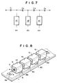
- the arrangement of a conventional band-pass filter using the dielectric resonator is illustrated in Fig. 7, in which 1A', 1B' and 1C' each denote a dielectric resonator whose outer conductor is grounded.
- 1A', 1B' and 1C' each denote a dielectric resonator whose outer conductor is grounded.
- a dielectric filter having a plurality of quarter-wavelength coaxial dielectric resonators, said resonators being each filled with a dielectric material between its inner and outer conductors, said resonators being connected in series; characterized in that the outer conductor of at least one of said quarter-wavelength coaxial dielectric resonators is grounded via a capacitance or an inductance.
- the above-described dielectric filter according to the present invention can be embodied as a filter as follows:
- a four-stage dielectric low-pass filter is shown in which four ⁇ /4 coaxial dielectric resonators 1A, 1B, 1C and 1D are used.
- the coaxial dielectric resonator is arranged so that a dielectric material 5 (for example, made of a barium titanate series substance of dielectric constant of about 93) is filled between a prismatic outer conductor 3 and a cylindrical inner conductor 4 with the outer and inner conductors 3 and 4 short-circuited at its one end surface, and it resonates when its length equals ⁇ /4 ( ⁇ denotes wavelength), as well known.
- a dielectric material 5 for example, made of a barium titanate series substance of dielectric constant of about 93
- Inner conductors 4 of the foregoing resonators 1A, 1B, 1C and 1D respectively are connected in series to each other via a lead 6.
- Each of the resonators is supported on the upper surface of a dielectric substrate 7 made of, for example, a Teflon (trademark).
- a dielectric substrate 7 made of, for example, a Teflon (trademark).
- electrode 8A of desired size connected to a lead 6 connected to the inner conductor of the resonator 1A and electrodes 8B, 8C, 8D and 8E of desired size connected to the outer conductor 3 of each resonator.
- a single grounded electrode 9 is formed opposed to the foregoing electrodes 8A through 8E.
- Capacitances C E1 , C E2 , C E3 , C E4 and C E5 are each arranged by these electrodes 8A through 8E and the grounded electrode 9.
- Fig. 10 illustrates the equivalent circuit.
- the frequency of the attenuating pole of the foregoing dielectric filter is determined by the resonant frequency of the dielectric resonator, and the frequency range and its depth ranging from the cut-off frequency up to the attenuating pole are determined by the characteristic impedance of the resonator and the capacitances C E1 through C E5 .
- Fig. 12 by way of example, illustratives a four-stage dielectric high-pass filter arranged by using four ⁇ /4 coaxial dielectric resonators 1A, 1B, 1C and 1D.
- the inner conductor 4 of the coaxial dielectric resonator is connected in series via the lead 6.
- a pattern coil 18A of desired size connected to the lead 6 connected to the inner conductor of the resonator 1A and pattern coils 18B, 18C, 18D and 18E of desired size connected to the outer conductor 3 of each resonator are formed to thereby form inductances L E1 , L E2 , L E3 , L E4 and L E5 .
- the equivalent circuit is illustrated in Fig. 13.
- the frequency of the attenuating pole of the foregoing dielectric filter is determined by the resonant frequency of the dielectric resonator, and the frequency range and its depth ranging from the cut-off frequency up to the attenuating pole are determined by the characteristic impedance of the resonator and the inductances L E1 through L E5 .
- Fig. 14 illustrates a specific example of the filter frequency characteristic according to this embodiment.
- the characteristic impedance Z O of the dielectric resonators 1A, 1B, 1C and 1D was 10 ⁇
- L E3 13 nH.
- Fig. 15 illustrates a four-stage dielectric band-pass filter arranged by using four ⁇ /4 coaxial dielectric resonators 1A, 1B, 1C and 1D.
- electrodes 27A, 27B, 27C, 27D, 27E, 28A, 28B, 28C and 28D are formed on the upper surface of the substrate 7 on which the resonator is supported. Electrodes 27B, 27C and 27D are connected to the outer conductor 3 of each resonator, and opposed to these electrodes, a single grounded electrode 9 is formed on the lower surface of the substrate 7. Capacitances C E1 , C E2 and C E3 are arranged by these electrodes 27B, 27C and 27D and the grounded electrode 9.
- electrodes 28A, 28B, 28C and 28D are each connected to the inner conductor 4 of each resonator by means of a lead, and electrodes 27A and 27E each serve as an input/output terminal.
- a pair of electrodes 27A and 28A, a pair of electrodes 27B and 28B, a pair of electrodes 27D and 28C and a pair of electrodes 27E and 28D each form capacitances C 1 , C 2 , C 3 and C 4 .
- the equivalent circuit is shown in Fig. 16.
- the frequency of the attenuating pole of the foregoing dielectric filter is determined by the resonant frequency of the dielectric resonator, and the frequency range and its depth ranging from the upper limit of the frequency passband up to the attenuating pole are determined by the characteristic impedance of the resonator and the capacitances C 1 , C 2 , C 3 , C 4 , C E1 , C E2 and C E3 .
- Fig. 17 illustrates a specific example of the filter frequency characteristic according to this embodiment.
- the characteristic impedance Z O of the dielectric resonators 1A, 1B, 1C and 1D was 7 ⁇
- C E2 5.8 pF
- the band-pass filter according to this embodiment is extremely small in insertion loss.
- Fig. 19 illustrates an example of the result obtained by the foregoing comparison.
- the characteristic impedance Z O of the dielectric resonators 1A, 1B and 1C was 8.3 ⁇
- C 2 4.1 pF
- A indicates the characteristic of the three-stage filter, B that of the four-stage filter.
- the loss value at the frequency at which the magnitude of the insertion loss becomes minimal equals 0.85 dB and, for the four-stage filter, the loss value at the frequency at which the magnitude of the insertion loss becomes minimal equals 1.20 dB, which is extremely small.
- Fig. 20 illustrates, by way of example, a four-stage dielectric band-pass filter arranged by using four ⁇ /4 coaxial dielectric resonators 1A, 1B, 1A' and 1B', in which two central stages connect the capacitances C 2 , C 3 and C 4 to the ⁇ /4 coaxial dielectric resonators 1A' and 1B' and the outer conductor of the dielectric resonator is directly grounded. That is, in this embodiment, a similar arrangement as in the conventional filter stage of Fig. 7 is used for part of the stages, in which embodiment, a useful attenuating pole can also be formed.
- the inner conductor and outer conductor of the adjacent dielectric resonators are connected via the capacitor, and the outer conductor of the dielectric resonator is grounded via the capacitors so that the attenuating pole may be available at a frequency higher than the upper limit of the frequency passband.
- coils may be used to form a band-pass filter having the attenuating pole at a frequency lower than the lower limit of the frequency passband.
- coils L 1 , L 2 , L 3 and L 4 may be connected to the dielectric resonators 1A, 1B, 1C and 1D while the outer conductor of the dielectric resonator may be grounded via coils L E1 , L E2 and L E3 so that a characteristic as shown in Fig. 23 may be achieved.
- the present invention since at least one stage is included in which the outer conductor of the ⁇ /4 coaxial dielectric resonator is grounded via the capacitances or inductances, it is possible to readily achieve a dielectric filter having the attenuating pole in the neighborhood of the frequency passband and small in insertion loss by utilizing the dielectric resonators of desired resonant frequency.
- the dielectric filter according to the present invention can be effectively used as the low-pass filter, high-pass filter and the band-pass filter in the high frequency range such as the microwave or the like.
Landscapes
- Physics & Mathematics (AREA)
- Electromagnetism (AREA)
- Control Of Motors That Do Not Use Commutators (AREA)
Abstract
Description
- The present invention relates to a dielectric filter using a λ/4 coaxial dielectric resonator and, in particular, to a dielectric filter having an attenuating pole in the neighborhood of the frequency passband in its filter frequency characteristic.
- The present invention can be applied to a low-pass filer, high-pass filter and band-pass filter in a high frequency range such as a microwave or the like.
- In general, as the low-pass filter, one having a basic arrangement as shown in Fig. 1 has been known, in which inductances L1, L2, etc. each disposed in series are grounded via capacitances CE1, CE2, CE3, etc.
- In addition, as a low-pass filter having an attenuating pole formed in the neighborhood of the cut-off frequency for achieving a steep attenuating characteristic, as shown in Fig. 2, one having an arrangement using a parallel connection of a capacitor C1 and a coil L1 and a parallel connection of a capacitor C2 and a coil L2 has been known.
- With such a low-pass filter, a stray capacitance as indicated by the broken line in Fig. 2 is generated to the LC parallel connection due to the arrangement of the used coil. This stray capacitance is substantially difficult to remove, and has a considerable distribution. This distribution in turn causes a distribution of the resonant frequency of the LC parallel connection or of the impedance in the frequency passband ultimately affecting the filter frequency characteristic. This effect, although small when the frequency is low, becomes greater if the frequency is high, thus causing the fluctuation of the attenuating pole frequency and the cut-off frequency or the increase of the mismatching loss in the frequency passband.
- Therefore, unless a considerable adjustment is made to the coil or capacitor, any desired filter frequency characteristic cannot be obtained to make it complicated and difficult to adjust the filter frequency characteristic.
- In addition, in general, as the high-pass filter, one having a basic arrangement as shown in Fig. 3 has been known, in which capacitances C1, C2, etc. each disposed in series are grounded via inductances LE1, LE2, LE3 and the like.
- In addition, as the high-pass filter having an attenuating pole formed in the neighborhood of the cut-off frequency for achieving a steep attenuating characteristic, as shown in Fig. 4, one having an arrangement using a parallel connection of the capacitor C1 and the coil L1 and a parallel connection of the capacitor C2 and the coil L2 has been known.
- However, such a high-pass filter also suffers from a similar problem as in the aforementioned low-pass filter and, unless a considerable adjustment is made to the coil or capacitor, a desired filter frequency characteristic cannot be achieved, and it is complicated or difficult to adjust the filter frequency characteristic.
- Further, in general, as the band-pass filter, one having a basic arrangement as shown in Fig. 5 has been known, in which capacitances C1, C2, C3, C4, etc. and inductances L1, L2, L3, L4, etc. each alternately disposed in series are grounded via capacitances CE1, CE2, CE3, etc.
- Still further, as the band-pass filter having an attenuating pole formed in the neighborhood of the frequency passband for achieving a steep attenuating characteristic, as shown in Fig. 6, one having an arrangement using a parallel connection of a capacitor CF1 and a coil L1, a parallel connection of a capacitor CF2 and a coil L2, a parallel connection of a capacitor CF3 and a coil L3 , a parallel connection of a capacitor CF4, and a coil L4 and the like has been known.
- Such a band-pass filter also suffers from a similar problem as in the aforementioned low-pass filter or high-pass filter and, unless a considerable adjustment is made to the coil or capacitor, no desired filter frequency characteristic is obtained and, it is complicated and difficult to adjust the filter frequency characteristic.
- Thus, it is proposed to use a λ/4 coaxial dielectric resonator using a dielectric material having a high dielectric constant in order to form a band-pass filter of a high frequency range. The arrangement of a conventional band-pass filter using the dielectric resonator is illustrated in Fig. 7, in which 1A', 1B' and 1C' each denote a dielectric resonator whose outer conductor is grounded. However, according to this arrangement, it is not possible to form the attenuating pole in the neighborhood of the upper or lower limit of the frequency passband to achieve the steep attenuating characteristic while, as the number of stages is increased, the insertion loss can be greatly increased.
- JP-A-60 065 601 and its corresponding English-language abstract published in "Patent Abstracts of Japan", vol. 9, no. 201, (E-336)(1924), on 17.08.1995, discloses a dielectric filter having a plurality of quarter-wavelength coaxial dielectric resonators, said resonators being each filled with a dielectric material between its inner and outer conductors, said resonators being connected in series.
- It is an object of the present invention to provide a dielectric filter having a reduced insertion loss and an attenuating pole at a desired frequency so that a desired filter frequency characteristic can be readily achieved.
- According to the present invention this object is achieved by a dielectric filter having a plurality of quarter-wavelength coaxial dielectric resonators, said resonators being each filled with a dielectric material between its inner and outer conductors, said resonators being connected in series; characterized in that the outer conductor of at least one of said quarter-wavelength coaxial dielectric resonators is grounded via a capacitance or an inductance.
- The above-described dielectric filter according to the present invention can be embodied as a filter as follows:
- (a) a low-pass filter in which the outer conductor of the λ/4 coaxial dielectric resonator in the at least one stage is grounded via the capacitance while the resonators in adjacent stages are connected to each other,
- (b) a high-pass filter in which the outer conductor of the resonator in the at least one stage is grounded via the inductance while the resonators in adjacent stages are connected to each other,
- (c) a band-pass filter in which the outer conductor of the resonator in the at least one stage is grounded via the capacitance, and adjacent stages are present in which the inner conductor of one stage is connected to the outer conductor of the other stage via a capacitance, and
- (d) a band-pass filter in which the outer conductor of the resonator in the at least one stage is grounded via the inductance, and adjacent stages are present in which the inner conductor of one stage is connected to the outer conductor of the other stage via an inductance.
-
- Figs. 1 through 7 are respectively a view of the arrangement of a conventional filter;
- Fig. 8 is a view of the arrangement of a dielectric low-pass filter according to the present invention:
- Fig. 9 is a cross-sectional view of a dielectric resonator;
- Fig. 10 is an equivalent circuit diagram of the filter of Fig. 8;
- Fig. 11 is a diagram of the filter frequency characteristic of the filter of Fig. 8;
- Fig. 12 is a view of the arrangement of a dielectric high-pass filter according to the present invention;
- Fig. 13 is an equivalent circuit diagram of the filter of Fig. 12;
- Fig. 14 is a diagram of the filter frequency characteristic of the filter of Fig. 12;
- Fig. 15 is a view of the arrangement of a dielectric band-pass filter according to the present invention;
- Fig. 16 is an equivalent circuit diagram of the filter of Fig. 15;
- Fig. 17 is a diagram of the filter frequency characteristic of the filter of Fig. 15;
- Fig. 18 is a view of the arrangement of another band-pass filter according to the present invention;
- Fig. 19 is a diagram for comparing the characteristics of the filter of Fig. 15 and that of Fig. 18;
- Fig. 20 is a view of the arrangement of a still another dielectric band-pass filter according to the present invention;
- Fig. 21 is a diagram of the filter frequency characteristic of the filter of Fig. 20;
- Fig. 22 is a view of the arrangement of a dielectric band-pass filter according to the present invention; and
- Fig. 23 is a diagram of the filter frequency characteristic of the filter of Fig. 22.
- Specific embodiments of the present invention are hereinafter described in greater detail with reference to the accompanying drawings.
- Referring to Fig. 8, by way of example, a four-stage dielectric low-pass filter is shown in which four λ/4 coaxial
dielectric resonators - As its cross-sectional view is shown in Fig. 9, the coaxial dielectric resonator is arranged so that a dielectric material 5 (for example, made of a barium titanate series substance of dielectric constant of about 93) is filled between a prismatic
outer conductor 3 and a cylindricalinner conductor 4 with the outer andinner conductors -
Inner conductors 4 of theforegoing resonators lead 6. Each of the resonators is supported on the upper surface of adielectric substrate 7 made of, for example, a Teflon (trademark). On the upper surface of thesubstrate 7, there are formed anelectrode 8A of desired size connected to alead 6 connected to the inner conductor of theresonator 1A andelectrodes outer conductor 3 of each resonator. Further, on the lower surface of thesubstrate 7, a single groundedelectrode 9 is formed opposed to the foregoingelectrodes 8A through 8E. Capacitances CE1, CE2, CE3, CE4 and CE5 are each arranged by theseelectrodes 8A through 8E and the groundedelectrode 9. Fig. 10 illustrates the equivalent circuit. - In such an arrangement, the frequency of the attenuating pole of the foregoing dielectric filter is determined by the resonant frequency of the dielectric resonator, and the frequency range and its depth ranging from the cut-off frequency up to the attenuating pole are determined by the characteristic impedance of the resonator and the capacitances CE1 through CE5.
- Fig. 11 illustrates a specific example of the filter frequency characteristic according to this embodiment, in which the characteristic impedance ZO of the
dielectric resonators - In such a low-pass filter, since the foregoing coaxial dielectric resonator has substantially no stray capacitance caused by the LC parallel connection, as indicated by broken line in Fig. 2, its filter frequency characteristic is stable. In addition, since the foregoing capacitances CE1 through CE5 can be adjusted including the stray capacitance between the outer conductor of the dielectric resonator and the ground, it is extremely easy to adjust the filter frequency characteristic.
- Fig. 12, by way of example, illustratives a four-stage dielectric high-pass filter arranged by using four λ/4 coaxial
dielectric resonators inner conductor 4 of the coaxial dielectric resonator is connected in series via thelead 6. On the upper surface of thesubstrate 7 on which each resonator is supported, apattern coil 18A of desired size connected to thelead 6 connected to the inner conductor of theresonator 1A and pattern coils 18B, 18C, 18D and 18E of desired size connected to theouter conductor 3 of each resonator are formed to thereby form inductances LE1, LE2, LE3, LE4 and LE5. The equivalent circuit is illustrated in Fig. 13. - With such an arrangement, the frequency of the attenuating pole of the foregoing dielectric filter is determined by the resonant frequency of the dielectric resonator, and the frequency range and its depth ranging from the cut-off frequency up to the attenuating pole are determined by the characteristic impedance of the resonator and the inductances LE1 through LE5.
- Fig. 14 illustrates a specific example of the filter frequency characteristic according to this embodiment. Here, the characteristic impedance ZO of the
dielectric resonators - In such a high-pass filter, since the foregoing coaxial dielectric resonator has substantially no stray capacitance caused by parallel connection, as indicated by broken line in Fig. 4, its filter frequency characteristic is stable. In addition, since the foregoing inductances LE1 through LE5 can be adjusted including the stray capacitance between the outer conductor of the dielectric resonator and the ground, it is extremely easy to adjust the filter frequency characteristic.
- Fig. 15 illustrates a four-stage dielectric band-pass filter arranged by using four λ/4 coaxial
dielectric resonators substrate 7 on which the resonator is supported,electrodes Electrodes outer conductor 3 of each resonator, and opposed to these electrodes, a single groundedelectrode 9 is formed on the lower surface of thesubstrate 7. Capacitances CE1 , CE2 and CE3 are arranged by theseelectrodes electrode 9. In addition,electrodes inner conductor 4 of each resonator by means of a lead, andelectrodes electrodes electrodes 27B and 28B, a pair ofelectrodes electrodes - With such an arrangement, the frequency of the attenuating pole of the foregoing dielectric filter is determined by the resonant frequency of the dielectric resonator, and the frequency range and its depth ranging from the upper limit of the frequency passband up to the attenuating pole are determined by the characteristic impedance of the resonator and the capacitances C1, C2, C3, C4, CE1, CE2 and CE3.
- Fig. 17 illustrates a specific example of the filter frequency characteristic according to this embodiment. Here, the characteristic impedance ZO of the
dielectric resonators - With such a band-pass filter, since the foregoing coaxial dielectric resonator has substantially no stray capacitance caused by the LC parallel connection, as indicated by broken line in Fig. 6, its filter frequency characteristic is stable. In addition, since the foregoing capacitances CE1 through CE3 can be adjusted including the stray capacitance between the outer conductor of the dielectric resonator and the ground, it is extremely easy to adjust the filter frequency characteristic.
- The band-pass filter according to this embodiment is extremely small in insertion loss. Here, let us compare the characteristics of a three-stage band-pass filter of Fig. 18 and the four-stage band-pass filter of Fig. 16. Fig. 19 illustrates an example of the result obtained by the foregoing comparison. Here, in the three-stage filter of Fig. 18, the characteristic impedance ZO of the
dielectric resonators dielectric resonator - Fig. 20 illustrates, by way of example, a four-stage dielectric band-pass filter arranged by using four λ/4 coaxial
dielectric resonators dielectric resonators 1A' and 1B' and the outer conductor of the dielectric resonator is directly grounded. That is, in this embodiment, a similar arrangement as in the conventional filter stage of Fig. 7 is used for part of the stages, in which embodiment, a useful attenuating pole can also be formed. - Fig. 21 illustrates a specific example of the filter frequency characteristic according to this embodiment, in which the characteristic impedance ZO of the
dielectric resonators dielectric resonators 1A' and 1B' was 7.95Ω, the resonant frequency F0 930 MHz, CE1 = CE2 = 3pF, C1 = C2 = C4 = C5 = 2pF, C3 = 0.5 pF. - Incidentally, in the foregoing embodiment, the inner conductor and outer conductor of the adjacent dielectric resonators are connected via the capacitor, and the outer conductor of the dielectric resonator is grounded via the capacitors so that the attenuating pole may be available at a frequency higher than the upper limit of the frequency passband. However, in place of these capacitors, coils may be used to form a band-pass filter having the attenuating pole at a frequency lower than the lower limit of the frequency passband.
- For example, as shown in Fig. 22, coils L1, L2, L3 and L4 may be connected to the
dielectric resonators dielectric resonators - As described above, according to the present invention, since at least one stage is included in which the outer conductor of the λ/4 coaxial dielectric resonator is grounded via the capacitances or inductances, it is possible to readily achieve a dielectric filter having the attenuating pole in the neighborhood of the frequency passband and small in insertion loss by utilizing the dielectric resonators of desired resonant frequency.
- The dielectric filter according to the present invention can be effectively used as the low-pass filter, high-pass filter and the band-pass filter in the high frequency range such as the microwave or the like.
Claims (12)
- A dielectric filter having a plurality of quarter-wavelength coaxial dielectric resonators (1A, 1B, 1C, 1D), said resonators (1A, 1B, 1C, 1D) being each filled with a dielectric material (5) between its inner and outer conductors (3, 4), said resonators (1A, 1B, 1C, 1D) being connected in series;
characterized in that
the outer conductor (3) of at least one of said quarter-wavelength coaxial dielectric resonators (1A, 1B, 1C, 1D) is grounded via a capacitance (CE2, CE3, CE4, CE5) or an inductance (LE2, LE3, LE4, LE5). - A dielectric filter according to claim 1,
characterized in that said dielectric filter is adapted to form a low-pass filter wherein said outer conductor (3) of said at least one of said quarter-wavelength coaxial dielectric resonators (1A, 1B, 1C, 1D) is grounded via said capacitance (CE2, CE3, CE4, CE5). - A dielectric filter according to claim 1,
characterized in that said dielectric filter is adapted to form a high-pass filter wherein said outer conductor (3) of said at least one of said quarter-wavelength coaxial dielectric resonators (1A, 1B, 1C, 1D) is grounded via said inductance (LE2, LE3, LE4, LE5). - A dielectric filter according to claim 1,
characterized in thatsaid dielectric filter is adapted to form a band-pass filter wherein said outer conductor (3) of said at least one of said quarter-wavelength coaxial dielectric resonators (1A, 1B, 1C, 1D) is grounded via said capacitance (CE1, CE2, CE3); andadjacent quarter-wavelength coaxial dielectric resonators (1B, 1C) are present wherein said inner conductor (4) of one quarter-wavelength coaxial dielectric resonator (1B, 1C) is connected to said outer conductor (3) of said other quarter-wavelength coaxial dielectric resonator (1A, 1D) via a capacitance (C2, C3). - A dielectric band-pass filter according to claim 4,
characterized by at least one quarter-wavelength coaxial dielectric resonator (1A', 1B') to which a capacitance (C2, C3, C4) is connected and whose outer conductor (3) is directly grounded. - A dielectric filter according to claim 1,
characterized in thatsaid dielectric filter is adapted to form a band-pass filter wherein said outer conductor (3) of said at least one of said quarter-wavelength coaxial dielectric resonators (1A, 1B, 1C, 1D) is grounded via said inductance (LE1, LE2, LE3); andadjacent quarter-wavelength coaxial dielectric resonators (1B; 1C) are present wherein said inner conductor (4) of one quarter-wavelength coaxial dielectric resonator (1B; 1C) is connected to said outer conductor (3) of said other quarter-wavelength coaxial dielectric resonator (1A, 1D) via an inductance (L2, L3). - A dielectric band-pass filter according to claim 6, characterized by at least one quarter-wavelength coaxial dielectric resonator to which an inductance is connected and whose outer conductor (3) is directly grounded.
- A dielectric filter according to any of claims 1 to 7, characterized in that all of said quarter-wavelength coaxial dielectric resonators (1A, 1B, 1C, 1D) are supported on a substrate (7).
- A dielectric filter according to any of claims 1, 2 and 4, characterized in thatall of said quarter-wavelength coaxial dielectric resonators (1A, 1B, 1C, 1D) are supported on a first surface of a substrate (7); andsaid capacitance (CE2, CE3, CE4, CE5) existing at the grounding path of said outer conductor (3) of said quarter-wavelength coaxial dielectric resonator (1A, 1B, 1C, 1D) comprises an electrode (8B, 8C, 8D, 8E) formed on said first surface of said substrate (7) and a grounded electrode (9) formed on a second surface of said substrate (7).
- A dielectric filter according to any of claims 1, 3 and 6, characterized in thatall of said quarter-wavelength coaxial dielectric resonators (1A, 1B, 1C, 1D) are supported on a first surface of a substrate (7);said inductance (LE2, LE3, LE4, LE5) existing at the grounding path of said outer conductor (3) of said quarter-wavelength coaxial dielectric resonator (1A, 1B, 1C, 1D) comprises a pattern coil (18B, 18C, 18D, 18E) formed on said first surface of said substrate (7); anda grounded electrode (9) connected to said pattern coil (18B, 18C, 18D, 18E) is formed on a second surface of said substrate (7).
- A dielectric filter according to claim 4 or 5,
characterized in thatall of said quarter-wavelength coaxial dielectric resonators (1A, 1B, 1C, 1D) are supported on a first surface of a substrate (7); andsaid capacitance (C1, C2, C3, C4) existing outside the grounding path of said outer conductor (3) of said quarter-wavelength coaxial dielectric resonator (1A, 1B, 1C, 1D) comprises a pair of electrodes (27A, 28A, 27B, 28B, 27D, 28C, 27E, 28D) formed on said first surface of said substrate (7). - A dielectric filter according to claim 6 or 7,
characterized in thatall of said quarter-wavelength coaxial dielectric resonators (1A, 1B, 1C, 1D) are supported on a first surface of a substrate (7); andsaid inductance (L1, L2, L3, L4) existing outside the grounding path of said outer conductor (3) of said quarter-wavelength coaxial dielectric resonator (1A, 1B, 1C, 1D) comprises a pattern coil formed on said first surface of said substrate (7).
Applications Claiming Priority (7)
| Application Number | Priority Date | Filing Date | Title |
|---|---|---|---|
| JP2414043A JP2587880B2 (en) | 1990-12-26 | 1990-12-26 | Dielectric low-pass filter |
| JP414043/90 | 1990-12-26 | ||
| JP35645/91 | 1991-02-04 | ||
| JP3035645A JP2594708B2 (en) | 1991-02-04 | 1991-02-04 | Dielectric high-pass filter |
| JP4063591A JPH04259101A (en) | 1991-02-13 | 1991-02-13 | dielectric bandpass filter |
| JP40635/91 | 1991-02-13 | ||
| PCT/JP1991/001751 WO1992012546A1 (en) | 1990-12-26 | 1991-12-24 | Dielectric filter |
Publications (3)
| Publication Number | Publication Date |
|---|---|
| EP0519080A1 EP0519080A1 (en) | 1992-12-23 |
| EP0519080A4 EP0519080A4 (en) | 1993-06-09 |
| EP0519080B1 true EP0519080B1 (en) | 1997-03-19 |
Family
ID=27288823
Family Applications (1)
| Application Number | Title | Priority Date | Filing Date |
|---|---|---|---|
| EP92901463A Expired - Lifetime EP0519080B1 (en) | 1990-12-26 | 1991-12-24 | Dielectric filter |
Country Status (4)
| Country | Link |
|---|---|
| US (1) | US5493261A (en) |
| EP (1) | EP0519080B1 (en) |
| DE (1) | DE69125273T2 (en) |
| WO (1) | WO1992012546A1 (en) |
Families Citing this family (7)
| Publication number | Priority date | Publication date | Assignee | Title |
|---|---|---|---|---|
| GB2276276A (en) * | 1993-03-17 | 1994-09-21 | Marconi Gec Ltd | Coaxial resonator and multi-layer circuit board arrangement for a band stop filter |
| JPH09162766A (en) * | 1995-12-04 | 1997-06-20 | Alps Electric Co Ltd | Satellite receiver |
| ITMI981563A1 (en) * | 1998-07-09 | 2000-01-09 | Alsthom Cge Alcatel | DEVICE INCLUDING A COAXIAL DIELECTRIC RESONATOR MOUNTED ON A LOW PHASE NOISE MICROSTRIP AND METHOD TO REDUCE THE |
| US20020023273A1 (en) * | 2000-08-14 | 2002-02-21 | Hanmi Pharm. Co., Ltd. | Apparatus for providing a multiple internet connection service using a hybrid fiber coaxial cable network |
| JP5907124B2 (en) * | 2013-07-24 | 2016-04-20 | 株式会社村田製作所 | High frequency components and filter components |
| US10050322B2 (en) | 2014-03-24 | 2018-08-14 | Telefonaktiebolaget Lm Ericsson (Publ) | Coaxial filter and method for manufacturing the same |
| JP6222360B2 (en) * | 2014-06-25 | 2017-11-01 | 宇部興産株式会社 | Dielectric non-contact transmission device and non-contact transmission method |
Family Cites Families (9)
| Publication number | Priority date | Publication date | Assignee | Title |
|---|---|---|---|---|
| US4245198A (en) * | 1978-05-10 | 1981-01-13 | Murata Manufacturing Co., Ltd. | High frequency filter device |
| JPS5657304A (en) * | 1979-10-15 | 1981-05-19 | Murata Mfg Co Ltd | Branching filter using dielectric coaxial resonator |
| JPS6065601A (en) * | 1983-09-21 | 1985-04-15 | Oki Electric Ind Co Ltd | Dielectric filter |
| GB2165098B (en) * | 1984-09-27 | 1988-05-25 | Motorola Inc | Radio frequency filters |
| JPS61208902A (en) * | 1985-03-13 | 1986-09-17 | Murata Mfg Co Ltd | Mic type dielectric filter |
| JPS62128601A (en) * | 1985-11-29 | 1987-06-10 | Murata Mfg Co Ltd | Microwave filter |
| JPS6324703A (en) * | 1986-07-16 | 1988-02-02 | Murata Mfg Co Ltd | Filter |
| JPH063842B2 (en) * | 1987-07-31 | 1994-01-12 | 株式会社村田製作所 | Microwave filter |
| JPH0216802A (en) * | 1988-07-04 | 1990-01-19 | Murata Mfg Co Ltd | Band elimination filter |
-
1991
- 1991-12-24 EP EP92901463A patent/EP0519080B1/en not_active Expired - Lifetime
- 1991-12-24 DE DE69125273T patent/DE69125273T2/en not_active Expired - Fee Related
- 1991-12-24 WO PCT/JP1991/001751 patent/WO1992012546A1/en not_active Ceased
-
1994
- 1994-07-22 US US08/279,471 patent/US5493261A/en not_active Expired - Fee Related
Also Published As
| Publication number | Publication date |
|---|---|
| DE69125273T2 (en) | 1997-08-28 |
| EP0519080A4 (en) | 1993-06-09 |
| EP0519080A1 (en) | 1992-12-23 |
| WO1992012546A1 (en) | 1992-07-23 |
| US5493261A (en) | 1996-02-20 |
| DE69125273D1 (en) | 1997-04-24 |
Similar Documents
| Publication | Publication Date | Title |
|---|---|---|
| US5227748A (en) | Filter with electrically adjustable attenuation characteristic | |
| US3879690A (en) | Distributed transmission line filter | |
| US5293141A (en) | Dielectric filter having external connection terminals on dielectric substrate and antenna duplexer using the same | |
| US5416454A (en) | Stripline filter with a high side transmission zero | |
| US6686815B1 (en) | Microwave filter | |
| US5066933A (en) | Band-pass filter | |
| US5812036A (en) | Dielectric filter having intrinsic inter-resonator coupling | |
| JP3344428B2 (en) | Dielectric resonator and dielectric resonator component | |
| CA2089155C (en) | Multi-stage monolithic ceramic bandstop filter with isolated filter stages | |
| US6720849B2 (en) | High frequency filter, filter device, and electronic apparatus incorporating the same | |
| US4816788A (en) | High frequency band-pass filter | |
| US4837534A (en) | Ceramic block filter with bidirectional tuning | |
| US5187459A (en) | Compact coupled line filter circuit | |
| US5493261A (en) | Dielectric filter using quarter wavelength coaxial dielectric resonators connected in series | |
| JPS59114902A (en) | Dielectric filter | |
| EP0576273B1 (en) | Coaxial resonator and dielectric filter using the same | |
| US6525625B1 (en) | Dielectric duplexer and communication apparatus | |
| JP3050090B2 (en) | Dielectric filter | |
| RU2222076C2 (en) | Wide-rejection-band microstrip bandpass filter | |
| JPH03252201A (en) | Band attenuating filter | |
| KR100501928B1 (en) | Second order bandpass filter using capacitively loaded multi-layer 1/4 wavelength resonator | |
| JPS6138885B2 (en) | ||
| JP2005150927A (en) | Dielectric filter, dielectric duplexer, and communication device | |
| KR100314087B1 (en) | A ceramic filter | |
| JPS633209Y2 (en) |
Legal Events
| Date | Code | Title | Description |
|---|---|---|---|
| PUAI | Public reference made under article 153(3) epc to a published international application that has entered the european phase |
Free format text: ORIGINAL CODE: 0009012 |
|
| 17P | Request for examination filed |
Effective date: 19920825 |
|
| AK | Designated contracting states |
Kind code of ref document: A1 Designated state(s): DE FR GB IT |
|
| A4 | Supplementary search report drawn up and despatched |
Effective date: 19930421 |
|
| AK | Designated contracting states |
Kind code of ref document: A4 Designated state(s): DE FR GB IT |
|
| 17Q | First examination report despatched |
Effective date: 19950403 |
|
| GRAG | Despatch of communication of intention to grant |
Free format text: ORIGINAL CODE: EPIDOS AGRA |
|
| GRAH | Despatch of communication of intention to grant a patent |
Free format text: ORIGINAL CODE: EPIDOS IGRA |
|
| GRAH | Despatch of communication of intention to grant a patent |
Free format text: ORIGINAL CODE: EPIDOS IGRA |
|
| GRAA | (expected) grant |
Free format text: ORIGINAL CODE: 0009210 |
|
| AK | Designated contracting states |
Kind code of ref document: B1 Designated state(s): DE FR GB IT |
|
| PG25 | Lapsed in a contracting state [announced via postgrant information from national office to epo] |
Ref country code: IT Free format text: LAPSE BECAUSE OF FAILURE TO SUBMIT A TRANSLATION OF THE DESCRIPTION OR TO PAY THE FEE WITHIN THE PRE;WARNING: LAPSES OF ITALIAN PATENTS WITH EFFECTIVE DATE BEFORE 2007 MAY HAVE OCCURRED AT ANY TIME BEFORE 2007. THE CORRECT EFFECTIVE DATE MAY BE DIFFERENT FROM THE ONE RECORDED.SCRIBED TIME-LIMIT Effective date: 19970319 |
|
| REF | Corresponds to: |
Ref document number: 69125273 Country of ref document: DE Date of ref document: 19970424 |
|
| ET | Fr: translation filed | ||
| PLBE | No opposition filed within time limit |
Free format text: ORIGINAL CODE: 0009261 |
|
| STAA | Information on the status of an ep patent application or granted ep patent |
Free format text: STATUS: NO OPPOSITION FILED WITHIN TIME LIMIT |
|
| 26N | No opposition filed | ||
| REG | Reference to a national code |
Ref country code: GB Ref legal event code: IF02 |
|
| PGFP | Annual fee paid to national office [announced via postgrant information from national office to epo] |
Ref country code: GB Payment date: 20041214 Year of fee payment: 14 |
|
| PGFP | Annual fee paid to national office [announced via postgrant information from national office to epo] |
Ref country code: FR Payment date: 20041221 Year of fee payment: 14 |
|
| PGFP | Annual fee paid to national office [announced via postgrant information from national office to epo] |
Ref country code: DE Payment date: 20050131 Year of fee payment: 14 |
|
| PG25 | Lapsed in a contracting state [announced via postgrant information from national office to epo] |
Ref country code: GB Free format text: LAPSE BECAUSE OF NON-PAYMENT OF DUE FEES Effective date: 20051224 |
|
| PG25 | Lapsed in a contracting state [announced via postgrant information from national office to epo] |
Ref country code: DE Free format text: LAPSE BECAUSE OF NON-PAYMENT OF DUE FEES Effective date: 20060701 |
|
| GBPC | Gb: european patent ceased through non-payment of renewal fee |
Effective date: 20051224 |
|
| PG25 | Lapsed in a contracting state [announced via postgrant information from national office to epo] |
Ref country code: FR Free format text: LAPSE BECAUSE OF NON-PAYMENT OF DUE FEES Effective date: 20060831 |
|
| REG | Reference to a national code |
Ref country code: FR Ref legal event code: ST Effective date: 20060831 |