EP0519027B1 - Doormat and apparatus for producing the same - Google Patents
Doormat and apparatus for producing the same Download PDFInfo
- Publication number
- EP0519027B1 EP0519027B1 EP92900787A EP92900787A EP0519027B1 EP 0519027 B1 EP0519027 B1 EP 0519027B1 EP 92900787 A EP92900787 A EP 92900787A EP 92900787 A EP92900787 A EP 92900787A EP 0519027 B1 EP0519027 B1 EP 0519027B1
- Authority
- EP
- European Patent Office
- Prior art keywords
- doormat
- corrugated
- bands
- roller
- extruded
- Prior art date
- Legal status (The legal status is an assumption and is not a legal conclusion. Google has not performed a legal analysis and makes no representation as to the accuracy of the status listed.)
- Expired - Lifetime
Links
Images


Classifications
-
- A—HUMAN NECESSITIES
- A47—FURNITURE; DOMESTIC ARTICLES OR APPLIANCES; COFFEE MILLS; SPICE MILLS; SUCTION CLEANERS IN GENERAL
- A47L—DOMESTIC WASHING OR CLEANING; SUCTION CLEANERS IN GENERAL
- A47L23/00—Cleaning footwear
- A47L23/22—Devices or implements resting on the floor for removing mud, dirt, or dust from footwear
- A47L23/24—Rigid cleaning-gratings; Tread plates or scrapers for cleaning the soles of footwear
-
- B—PERFORMING OPERATIONS; TRANSPORTING
- B29—WORKING OF PLASTICS; WORKING OF SUBSTANCES IN A PLASTIC STATE IN GENERAL
- B29D—PRODUCING PARTICULAR ARTICLES FROM PLASTICS OR FROM SUBSTANCES IN A PLASTIC STATE
- B29D99/00—Subject matter not provided for in other groups of this subclass
- B29D99/0057—Producing floor coverings
-
- B—PERFORMING OPERATIONS; TRANSPORTING
- B29—WORKING OF PLASTICS; WORKING OF SUBSTANCES IN A PLASTIC STATE IN GENERAL
- B29L—INDEXING SCHEME ASSOCIATED WITH SUBCLASS B29C, RELATING TO PARTICULAR ARTICLES
- B29L2031/00—Other particular articles
- B29L2031/30—Vehicles, e.g. ships or aircraft, or body parts thereof
- B29L2031/3005—Body finishings
- B29L2031/3017—Floor coverings
-
- Y—GENERAL TAGGING OF NEW TECHNOLOGICAL DEVELOPMENTS; GENERAL TAGGING OF CROSS-SECTIONAL TECHNOLOGIES SPANNING OVER SEVERAL SECTIONS OF THE IPC; TECHNICAL SUBJECTS COVERED BY FORMER USPC CROSS-REFERENCE ART COLLECTIONS [XRACs] AND DIGESTS
- Y10—TECHNICAL SUBJECTS COVERED BY FORMER USPC
- Y10T—TECHNICAL SUBJECTS COVERED BY FORMER US CLASSIFICATION
- Y10T428/00—Stock material or miscellaneous articles
- Y10T428/24—Structurally defined web or sheet [e.g., overall dimension, etc.]
- Y10T428/24628—Nonplanar uniform thickness material
- Y10T428/24669—Aligned or parallel nonplanarities
- Y10T428/24694—Parallel corrugations
- Y10T428/24711—Plural corrugated components
-
- Y—GENERAL TAGGING OF NEW TECHNOLOGICAL DEVELOPMENTS; GENERAL TAGGING OF CROSS-SECTIONAL TECHNOLOGIES SPANNING OVER SEVERAL SECTIONS OF THE IPC; TECHNICAL SUBJECTS COVERED BY FORMER USPC CROSS-REFERENCE ART COLLECTIONS [XRACs] AND DIGESTS
- Y10—TECHNICAL SUBJECTS COVERED BY FORMER USPC
- Y10T—TECHNICAL SUBJECTS COVERED BY FORMER US CLASSIFICATION
- Y10T428/00—Stock material or miscellaneous articles
- Y10T428/24—Structurally defined web or sheet [e.g., overall dimension, etc.]
- Y10T428/24777—Edge feature
-
- Y—GENERAL TAGGING OF NEW TECHNOLOGICAL DEVELOPMENTS; GENERAL TAGGING OF CROSS-SECTIONAL TECHNOLOGIES SPANNING OVER SEVERAL SECTIONS OF THE IPC; TECHNICAL SUBJECTS COVERED BY FORMER USPC CROSS-REFERENCE ART COLLECTIONS [XRACs] AND DIGESTS
- Y10—TECHNICAL SUBJECTS COVERED BY FORMER USPC
- Y10T—TECHNICAL SUBJECTS COVERED BY FORMER US CLASSIFICATION
- Y10T428/00—Stock material or miscellaneous articles
- Y10T428/24—Structurally defined web or sheet [e.g., overall dimension, etc.]
- Y10T428/24942—Structurally defined web or sheet [e.g., overall dimension, etc.] including components having same physical characteristic in differing degree
Definitions
- the present invention relates to a doormat and an apparatus for producing the same.
- German patent No DE-14333 which was published in 1881.
- This document describes a mat formed by making parallel rows of short, spaced, transverse cuts through a rubber sheet, and then permanently deforming the rectangular sheet portions defined between adjacent cuts in each row to form alternately upwardly and downwardly deflected sheet portions along the length of each row.
- the cuts in each neighbouring pair of parallel rows are offset from each other along the length of the rows by a distance half of that between the cuts in each row.
- the cuts in all the rows are equally and evenly spaced.
- the invention provides a doormat and an apparatus for manufacturing a doormat as defined in the appendant independent claims. Preferred features of the invention are defined in dependent subclaims.
- the invention may provide a doormat having an excellent cushiony effect when people coming and going step on it when it is laid by a door or a gate, due to the spaces formed in the doormat by the corrugation of the bands of which it is formed, so as to solve the problems of the prior art doormats described above.
- the doormat of the invention may be made of synthetic resin sheet.
- the invention may provide a doormat which is convenient to use, and eliminates excellently muck adhered to the outsoles of shoes because of its good restoring force and elasticity.
- convexities are provided on surfaces of the corrugated bands of the doormat to prevent slip during use.
- the invention may advantageously provide an apparatus which comprises a simple structure and may easily manufacture the above doormat.
- Figure 1 is a perspective view of a doormat embodying the present invention.
- Figure 2 is a side view of the above doormat.
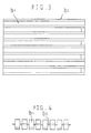
- Figure 3 is a plan view of the above doormat.
- Figure 4 is a front view of the above doormat.
- Each (A), (B), (C) and (D) of Figure 5 is a plan view of the doormat prepared with bands having various convexities on the surfaces thereof.
- Figure 6 is a schematic view of the apparatus for preparing the doormat according to the present invention.
- Figure 7 is a plan view of the roller of the above apparatus.
- Figure 8 is a plan view of an alternative roller for the above apparatus.
- the synthetic resin composition formed into the doormat according to the present invention must be composed of materials which have excellent waterproofing, wear resistance, soluble property, elasticity and the like.
- organic polymers having such characteristics are polyvinyl chloride, polyesters, polyurethanes, polypropylenes, polyethylenes, polystyrenes and various synthetic rubbers.
- FIG. 1 is a perspective view of a doormat according to a preferred embodiment of the present invention
- plural and continuous bands (b1) having 1 to 5mm of thickness and 2 to 20mm of width are combined alternately with straight bands (b2) having 0.2 to 5mm of thickness and 2 to 20mm of width.
- the corrugated bands (b1) are combined in different phases.
- FIG 2 is a side view of the above doormat, in which each corrugated band has different phase against the next corrugated band and such corrugated bands having different phases with each other are combined alternately. As a result, holes are formed in the mat in spaces between each corrugated band (b1) and straight band (b2).
- the space due to the phase difference between the corrugated bands (b1) gives a good cushiony effect so that feeling is good at stepping on the above doormat. Also, since it has good restoring force and elasticity, muck adhered to the outsoles of shoes is easily removed.
- Figure 3 is a plan view of the above doormat and Figure 4 is a front view of the above doormat.
- Figure 5 shows alternative embodiments of the doormat according to the present invention.
- a of Figure 5 represents that convexities (d1) are laterally or horizontally formed on the surface of each corrugated band (b1) and B represents that other convexities (d2) are formed in all directions on the surface of each corrugated band (b1).
- c represents that convexities (d3) are formed in all directions on the surface of each corrugated band (b1) and D represents that dotted convexities such as on the surface of an orange are irregularly formed. Therefore, slip is prevented when trampling the corrugated band (b1) in using the doormat.
- the above doormats have good cushiony effect by space due to corrugation of synthetic resin sheet. Also, they eliminate muck well from the outsoles of shoes because of their good restoring force and elasticity. Furthermore, they are convenient and may prevent slip because of various convexities formed on the surfaces of the corrugated bands.
- Figure 6 is a schematic view of an apparatus for preparing a doormat according to the present invention.
- the synthetic resin sheet (8) formed from an extrusion die (1) passes between rollers (2,3) having plural protuberances (4,4') in the lower part of the extrusion die (1), and is moulded into corrugated shape. Next, it passes by a guide roller (6) to be taken up by a take-up roller (7).
- Figure 7 is a plan view of the rollers (2,3) of the above apparatus.
- the drive roller (2) having plural corrugated protuberances (4) is meshed with the idler roller (3) having plural protuberances (4') in the lower part of the extrusion die (1).
- the idler roller (3) also rotates in attendance on the rotation of the drive roller (2).
- Walls (5,5') are optionally established between the protuberances, and each corrugated protuberance (4) formed on the drive roller (2) crosses with a corrugated protuberance (4') formed on the idler roller (3). Since the guide roller (6) is placed near the rollers (2,3), the synthetic resin sheet which has passed by the guide roller (6) is taken up by take-up roller (7).
- FIG 8 is a plan view of an alternative roller for the above apparatus.
- the drive roller (2') having plural corrugated protuberances (4'') is meshed with the idler roller (3') having plural corrugated protuberances (4''') in the lower part of the extrusion die (1).
- the idler roller (3') also rotates in attendance on the rotation of the drive roller (2').
- a corrugated protuberance (4'') formed on the drive roller (2') crosses with the corrugated protuberance (4''') formed on the idler roller (3'). Since the guide roller (6) is placed near rollers (2',3'), the synthetic resin sheet which has passed by the guide roller (6) is taken up by take-up roller (7).
- the doormat prepared by the above process may be cut to optional size according to use.
- the structure of the apparatus for preparing the doormat is very simple and the process for preparing the doormat is also easy in the case of use of the above apparatus. Accordingly, efficiency of work can be accelerated and a doormat having good qualities can be prepared.
Landscapes
- Engineering & Computer Science (AREA)
- Mechanical Engineering (AREA)
- Extrusion Moulding Of Plastics Or The Like (AREA)
- Carpets (AREA)
- Details Or Accessories Of Spraying Plant Or Apparatus (AREA)
- Treatment Of Fiber Materials (AREA)
- Special Wing (AREA)
- Footwear And Its Accessory, Manufacturing Method And Apparatuses (AREA)
- Securing Of Glass Panes Or The Like (AREA)
Abstract
Description
- The present invention relates to a doormat and an apparatus for producing the same.
- Various kinds of doormats have been used because a room was stained with muck adhered to the outsoles of shoes in the case of entering a room with stained shoes. To date, metallic coil spring bonded in a state of sheet or pile has been used as a doormat. Recently, synthetic resin was extruded in a fine fiber, and then the fibers got tangled with each other irregularly in a state of coil. The sheet thus obtained was used as a doormat. Of these types, the doormat made of metallic coil spring easily eliminated muck adhered to the outsoles of shoes. Such metallic doormats, however, had a disadvantage that it was difficult to shake fine muck from boots since the scraping effect was reduced by crushing of the metallic coil spring in using doormat. Another disadvantage was that it had poor feeling because of its hardness. The doormat made of pile had disadvantages in that it was inconvenient in wetting and therefore it had to be dry. Furthermore, it could hardly eliminate muck. Also, although the pile doormat eliminated well muck adhered to the outsoles of shoes, the muck when irregularly tangled in the apertures of the coil was difficult to eliminate.
- A prior art doormat is described in German patent No DE-14333, which was published in 1881. This document describes a mat formed by making parallel rows of short, spaced, transverse cuts through a rubber sheet, and then permanently deforming the rectangular sheet portions defined between adjacent cuts in each row to form alternately upwardly and downwardly deflected sheet portions along the length of each row. The cuts in each neighbouring pair of parallel rows are offset from each other along the length of the rows by a distance half of that between the cuts in each row. The cuts in all the rows are equally and evenly spaced.
- The invention provides a doormat and an apparatus for manufacturing a doormat as defined in the appendant independent claims. Preferred features of the invention are defined in dependent subclaims.
- Advantageously the invention may provide a doormat having an excellent cushiony effect when people coming and going step on it when it is laid by a door or a gate, due to the spaces formed in the doormat by the corrugation of the bands of which it is formed, so as to solve the problems of the prior art doormats described above.
- Preferably the doormat of the invention may be made of synthetic resin sheet.
- Preferably the invention may provide a doormat which is convenient to use, and eliminates excellently muck adhered to the outsoles of shoes because of its good restoring force and elasticity.
- In a preferred embodiment, convexities are provided on surfaces of the corrugated bands of the doormat to prevent slip during use.
- In a further aspect the invention may advantageously provide an apparatus which comprises a simple structure and may easily manufacture the above doormat.
- Figure 1 is a perspective view of a doormat embodying the present invention.
- Figure 2 is a side view of the above doormat.
- Figure 3 is a plan view of the above doormat.
- Figure 4 is a front view of the above doormat.
Each (A), (B), (C) and (D) of Figure 5 is a plan view of the doormat prepared with bands having various convexities on the surfaces thereof. - Figure 6 is a schematic view of the apparatus for preparing the doormat according to the present invention.
- Figure 7 is a plan view of the roller of the above apparatus.
- Figure 8 is a plan view of an alternative roller for the above apparatus.
- The synthetic resin composition formed into the doormat according to the present invention must be composed of materials which have excellent waterproofing, wear resistance, soluble property, elasticity and the like. Examples of organic polymers having such characteristics are polyvinyl chloride, polyesters, polyurethanes, polypropylenes, polyethylenes, polystyrenes and various synthetic rubbers.
- The illustrations in Figure 1 to Figure 8 more clearly show preferred embodiments of the present invention.
- As illustrated in Figure 1 which is a perspective view of a doormat according to a preferred embodiment of the present invention, plural and continuous bands (b₁) having 1 to 5mm of thickness and 2 to 20mm of width are combined alternately with straight bands (b₂) having 0.2 to 5mm of thickness and 2 to 20mm of width. The corrugated bands (b₁) are combined in different phases.
- Figure 2 is a side view of the above doormat, in which each corrugated band has different phase against the next corrugated band and such corrugated bands having different phases with each other are combined alternately. As a result, holes are formed in the mat in spaces between each corrugated band (b₁) and straight band (b₂).
- Further, the space due to the phase difference between the corrugated bands (b₁) gives a good cushiony effect so that feeling is good at stepping on the above doormat. Also, since it has good restoring force and elasticity, muck adhered to the outsoles of shoes is easily removed.
- Figure 3 is a plan view of the above doormat and Figure 4 is a front view of the above doormat.
- Figure 5 shows alternative embodiments of the doormat according to the present invention. Thus A of Figure 5 represents that convexities (d₁) are laterally or horizontally formed on the surface of each corrugated band (b₁) and B represents that other convexities (d₂) are formed in all directions on the surface of each corrugated band (b₁). Also, c represents that convexities (d₃) are formed in all directions on the surface of each corrugated band (b₁) and D represents that dotted convexities such as on the surface of an orange are irregularly formed. Therefore, slip is prevented when trampling the corrugated band (b₁) in using the doormat.
- Therefore, the above doormats have good cushiony effect by space due to corrugation of synthetic resin sheet. Also, they eliminate muck well from the outsoles of shoes because of their good restoring force and elasticity. Furthermore, they are convenient and may prevent slip because of various convexities formed on the surfaces of the corrugated bands.
- Figure 6 is a schematic view of an apparatus for preparing a doormat according to the present invention. The synthetic resin sheet (8) formed from an extrusion die (1) passes between rollers (2,3) having plural protuberances (4,4') in the lower part of the extrusion die (1), and is moulded into corrugated shape. Next, it passes by a guide roller (6) to be taken up by a take-up roller (7).
- Figure 7 is a plan view of the rollers (2,3) of the above apparatus.
- As illustrated in Figure 7, the drive roller (2) having plural corrugated protuberances (4) is meshed with the idler roller (3) having plural protuberances (4') in the lower part of the extrusion die (1). When the drive roller (2) is rotated, the idler roller (3) also rotates in attendance on the rotation of the drive roller (2). Walls (5,5') are optionally established between the protuberances, and each corrugated protuberance (4) formed on the drive roller (2) crosses with a corrugated protuberance (4') formed on the idler roller (3). Since the guide roller (6) is placed near the rollers (2,3), the synthetic resin sheet which has passed by the guide roller (6) is taken up by take-up roller (7).
- Figure 8 is a plan view of an alternative roller for the above apparatus. The drive roller (2') having plural corrugated protuberances (4'') is meshed with the idler roller (3') having plural corrugated protuberances (4''') in the lower part of the extrusion die (1). In the case that the drive roller (2') is rotated, the idler roller (3') also rotates in attendance on the rotation of the drive roller (2'). Also, a corrugated protuberance (4'') formed on the drive roller (2') crosses with the corrugated protuberance (4''') formed on the idler roller (3'). Since the guide roller (6) is placed near rollers (2',3'), the synthetic resin sheet which has passed by the guide roller (6) is taken up by take-up roller (7).
- The doormat prepared by the above process may be cut to optional size according to use. The structure of the apparatus for preparing the doormat is very simple and the process for preparing the doormat is also easy in the case of use of the above apparatus. Accordingly, efficiency of work can be accelerated and a doormat having good qualities can be prepared.
Claims (10)
- A doormat in which plural and continuous corrugated bands (b₁) of 1 to 5mm thickness and 2 to 20mm width are alternately combined in different phase, a straight band of 0.1 to 5mm thickness and 2 to 20mm width being positioned between and linking the proximate edges of each neighbouring pair of corrugated bands.
- A doormat according to claim 1, in which water drainage holes are defined between adjacent corrugated and straight bands.
- A doormat according to any preceding claim, in which the corrugated bands (b₁) have different widths.
- A doormat according to any preceding claim, in which surface convexities are defined on the corrugated bands.
- A doormat according to claim 4, in which the surface convexities are lateral, longitudinal, dotted, or in all directions.
- An apparatus for manufacturing a doormat in which plural and continuous corrugated bands (b₁) of 1 to 5mm thickness and 2 to 20mm width are alternately combined in different phase, a straight band of 0.1 to 5mm thickness and 2 to 20mm width being positioned between and linking the proximate edges of each neighbouring pair of corrugated bands, comprising an extrusion die (1), a drive roller (2) and an idler roller (3) each having plural corrugated protuberances (4,4') for shaping material extruded from the extrusion die therebetween, a guide roller (6) placed near the drive and idler rollers (2,3) for guiding the shaped material, and a take-up roller (7) for taking up the shaped material, in which the drive roller (2) is meshed with the idler roller (3) such that the corrugated protuberances (4) on the drive roller (2) cross with the corrugated protuberances (4') on the idler roller (3).
- An apparatus according to claim 6, in which walls (5,5') are defined on the drive and idler rollers between the corrugated protuberances.
- An apparatus according to claim 6 or 7, in which the rollers are shaped so that water drainage holes are formed between adjacent corrugated and straight bands of the doormat.
- An apparatus according to claim 6, 7 or 8, in which the rollers are shaped so that the doormat comprises corrugated bands of different widths.
- An apparatus according to any of claims 6 to 9, in which the corrugated protuberances of the rollers are shaped so that the doormat comprises corrugated bands on which surface convexities are formed, the surface convexities being for example lateral, longitudinal, dotted or in all directions.
Applications Claiming Priority (3)
| Application Number | Priority Date | Filing Date | Title |
|---|---|---|---|
| KR9021958 | 1990-12-27 | ||
| KR1019900021958A KR920009271B1 (en) | 1990-12-27 | 1990-12-27 | A floorcloth and preparing method thereof |
| PCT/KR1991/000033 WO1992011798A1 (en) | 1990-12-27 | 1991-12-20 | Doormat and apparatus for producing the same |
Publications (2)
| Publication Number | Publication Date |
|---|---|
| EP0519027A1 EP0519027A1 (en) | 1992-12-23 |
| EP0519027B1 true EP0519027B1 (en) | 1996-03-06 |
Family
ID=19308595
Family Applications (1)
| Application Number | Title | Priority Date | Filing Date |
|---|---|---|---|
| EP92900787A Expired - Lifetime EP0519027B1 (en) | 1990-12-27 | 1991-12-20 | Doormat and apparatus for producing the same |
Country Status (10)
| Country | Link |
|---|---|
| US (1) | US5364687A (en) |
| EP (1) | EP0519027B1 (en) |
| JP (1) | JP2604956B2 (en) |
| KR (1) | KR920009271B1 (en) |
| AT (1) | ATE134848T1 (en) |
| AU (1) | AU651859B2 (en) |
| DE (1) | DE69117746T2 (en) |
| MY (1) | MY108654A (en) |
| TW (1) | TW224425B (en) |
| WO (1) | WO1992011798A1 (en) |
Families Citing this family (9)
| Publication number | Priority date | Publication date | Assignee | Title |
|---|---|---|---|---|
| DE29505064U1 (en) * | 1995-03-25 | 1996-07-25 | Heerklotz, Siegfried, Dipl.-Ing., 49143 Bissendorf | Flat cushion body |
| JP2001064953A (en) * | 1999-08-24 | 2001-03-13 | Three M Innovative Properties Co | Soil-sand removing and draining mat |
| DE20207605U1 (en) * | 2002-05-15 | 2003-01-16 | Franke, Edgar, 72275 Alpirsbach | Suspension mat to support seats |
| TW542319U (en) * | 2002-11-07 | 2003-07-11 | Deng-Ren Yang | Pulling force type buffering shock absorbing structure |
| US20040091674A1 (en) * | 2002-11-12 | 2004-05-13 | 3M Innovative Properties Company | Mat with elastic compressible elements |
| TWI361616B (en) | 2006-01-27 | 2012-04-01 | Mstar Semiconductor Inc | Edge adaptive de-interlacing apparatus and method thereof |
| US20080138565A1 (en) * | 2006-12-07 | 2008-06-12 | Chih-Hsiang Yang | Elastic pad |
| US8033249B1 (en) * | 2007-07-06 | 2011-10-11 | Purr-fect Pet Co. LLC | Pet litter mat |
| AU2011276287B2 (en) * | 2010-07-07 | 2017-03-02 | Bj2, Llc | Apparatus and method for making a corrugated product |
Family Cites Families (7)
| Publication number | Priority date | Publication date | Assignee | Title |
|---|---|---|---|---|
| DE14333C (en) * | P. MAC LELLAN in Glasgow | Rubber mat | ||
| DE942712C (en) * | 1952-04-04 | 1956-05-09 | Ulvsunda Gummifabriks Aktiebol | Rubber mat |
| US3235440A (en) * | 1962-08-13 | 1966-02-15 | Gould Emma | Mat and method for finishing a rough base |
| US3563839A (en) * | 1968-08-01 | 1971-02-16 | Foster Grant Co Inc | Method of forming weakened tear lines and the article formed thereby |
| US3893795A (en) * | 1970-08-20 | 1975-07-08 | Rowland Dev Corp | Embossing rolls with areas of differential hardness |
| US4631215B1 (en) * | 1983-11-10 | 1991-03-26 | Extruded article and method of making the same | |
| US4587148A (en) * | 1985-04-19 | 1986-05-06 | Minnesota Mining And Manufacturing Company | Flocked floor mat with foraminous layer |
-
1990
- 1990-12-27 KR KR1019900021958A patent/KR920009271B1/en not_active IP Right Cessation
-
1991
- 1991-12-19 MY MYPI91002355A patent/MY108654A/en unknown
- 1991-12-19 TW TW080109866A patent/TW224425B/zh active
- 1991-12-20 WO PCT/KR1991/000033 patent/WO1992011798A1/en active IP Right Grant
- 1991-12-20 DE DE69117746T patent/DE69117746T2/en not_active Expired - Fee Related
- 1991-12-20 AT AT92900787T patent/ATE134848T1/en not_active IP Right Cessation
- 1991-12-20 AU AU90513/91A patent/AU651859B2/en not_active Ceased
- 1991-12-20 JP JP4501779A patent/JP2604956B2/en not_active Expired - Lifetime
- 1991-12-20 EP EP92900787A patent/EP0519027B1/en not_active Expired - Lifetime
-
1992
- 1992-08-25 US US07/935,522 patent/US5364687A/en not_active Expired - Fee Related
Also Published As
| Publication number | Publication date |
|---|---|
| KR920009271B1 (en) | 1992-10-15 |
| KR920011442A (en) | 1992-07-24 |
| TW224425B (en) | 1994-06-01 |
| AU9051391A (en) | 1992-08-17 |
| MY108654A (en) | 1996-10-31 |
| EP0519027A1 (en) | 1992-12-23 |
| AU651859B2 (en) | 1994-08-04 |
| DE69117746D1 (en) | 1996-04-11 |
| WO1992011798A1 (en) | 1992-07-23 |
| US5364687A (en) | 1994-11-15 |
| DE69117746T2 (en) | 1996-08-08 |
| JP2604956B2 (en) | 1997-04-30 |
| JPH05504710A (en) | 1993-07-22 |
| ATE134848T1 (en) | 1996-03-15 |
Similar Documents
| Publication | Publication Date | Title |
|---|---|---|
| US10531711B2 (en) | Forming laminated touch fasteners | |
| FI56331C (en) | NATURAL PRODUCTS WITHOUT FOUNDATION AT THE FRAMSTAELLA DENSAMMA | |
| EP0519027B1 (en) | Doormat and apparatus for producing the same | |
| DE69707342T2 (en) | Multilayer textile structure containing fasteners for industrial purposes | |
| CA1309853C (en) | Nonwoven fabric and method of manufacture | |
| EP0836929B1 (en) | Sheet-like structure with surface protrusions for providing spacing, grip-enhancing, draining elements and the like | |
| CN1264469C (en) | Disposable dirt wiring-out implement and production method therefor | |
| RU2005124299A (en) | TWO COMPONENT MONOFIBER | |
| AU571269B2 (en) | Extruded article and method of making the same | |
| US4465724A (en) | Reticulate sheet product | |
| US4242409A (en) | Process for crimping a non-woven mat and foam structure produced therewith | |
| JP3354601B2 (en) | Extrusion die insert in extruder and method of extruding band material containing reinforcing cord using extrusion die insert | |
| GB2277259A (en) | Moulded floor covering with strips of fibrous tread surface | |
| JP2823532B2 (en) | Drain material for ground improvement | |
| CN1143771C (en) | Honeycomb-like shutter shaping method | |
| KR930000102B1 (en) | Underlay and method of producing the same | |
| GB2231262A (en) | Mats | |
| JPS6149092B2 (en) | ||
| US20020132087A1 (en) | Female engaging surface fastener having a backing and method of making same | |
| JPH0661817B2 (en) | Hollow molded article and manufacturing method thereof | |
| JPH04151236A (en) | Manufacture of fiber-filled rubber mat blank | |
| DE4320143A1 (en) | Seat cover | |
| JPH04151237A (en) | Manufacture of fiber-filled rubber mat blank |
Legal Events
| Date | Code | Title | Description |
|---|---|---|---|
| PUAI | Public reference made under article 153(3) epc to a published international application that has entered the european phase |
Free format text: ORIGINAL CODE: 0009012 |
|
| 17P | Request for examination filed |
Effective date: 19920827 |
|
| AK | Designated contracting states |
Kind code of ref document: A1 Designated state(s): AT CH DE FR GB IT LI NL SE |
|
| 17Q | First examination report despatched |
Effective date: 19931126 |
|
| GRAA | (expected) grant |
Free format text: ORIGINAL CODE: 0009210 |
|
| AK | Designated contracting states |
Kind code of ref document: B1 Designated state(s): AT CH DE FR GB IT LI NL SE |
|
| PG25 | Lapsed in a contracting state [announced via postgrant information from national office to epo] |
Ref country code: NL Free format text: LAPSE BECAUSE OF FAILURE TO SUBMIT A TRANSLATION OF THE DESCRIPTION OR TO PAY THE FEE WITHIN THE PRESCRIBED TIME-LIMIT Effective date: 19960306 Ref country code: LI Effective date: 19960306 Ref country code: IT Free format text: LAPSE BECAUSE OF FAILURE TO SUBMIT A TRANSLATION OF THE DESCRIPTION OR TO PAY THE FEE WITHIN THE PRE;WARNING: LAPSES OF ITALIAN PATENTS WITH EFFECTIVE DATE BEFORE 2007 MAY HAVE OCCURRED AT ANY TIME BEFORE 2007. THE CORRECT EFFECTIVE DATE MAY BE DIFFERENT FROM THE ONE RECORDED.SCRIBED TIME-LIMIT Effective date: 19960306 Ref country code: CH Effective date: 19960306 Ref country code: AT Effective date: 19960306 |
|
| REF | Corresponds to: |
Ref document number: 134848 Country of ref document: AT Date of ref document: 19960315 Kind code of ref document: T |
|
| REF | Corresponds to: |
Ref document number: 69117746 Country of ref document: DE Date of ref document: 19960411 |
|
| ET | Fr: translation filed | ||
| PG25 | Lapsed in a contracting state [announced via postgrant information from national office to epo] |
Ref country code: SE Effective date: 19960606 |
|
| NLV1 | Nl: lapsed or annulled due to failure to fulfill the requirements of art. 29p and 29m of the patents act | ||
| REG | Reference to a national code |
Ref country code: CH Ref legal event code: PL |
|
| PG25 | Lapsed in a contracting state [announced via postgrant information from national office to epo] |
Ref country code: GB Effective date: 19961220 |
|
| PLBE | No opposition filed within time limit |
Free format text: ORIGINAL CODE: 0009261 |
|
| STAA | Information on the status of an ep patent application or granted ep patent |
Free format text: STATUS: NO OPPOSITION FILED WITHIN TIME LIMIT |
|
| 26N | No opposition filed | ||
| GBPC | Gb: european patent ceased through non-payment of renewal fee |
Effective date: 19961220 |
|
| PG25 | Lapsed in a contracting state [announced via postgrant information from national office to epo] |
Ref country code: FR Effective date: 19970829 |
|
| PG25 | Lapsed in a contracting state [announced via postgrant information from national office to epo] |
Ref country code: DE Effective date: 19970902 |
|
| REG | Reference to a national code |
Ref country code: FR Ref legal event code: ST |