EP0518372B1 - Rolling element cage constraint - Google Patents
Rolling element cage constraint Download PDFInfo
- Publication number
- EP0518372B1 EP0518372B1 EP92109949A EP92109949A EP0518372B1 EP 0518372 B1 EP0518372 B1 EP 0518372B1 EP 92109949 A EP92109949 A EP 92109949A EP 92109949 A EP92109949 A EP 92109949A EP 0518372 B1 EP0518372 B1 EP 0518372B1
- Authority
- EP
- European Patent Office
- Prior art keywords
- cage
- linear bearing
- stage
- resilient element
- end affixed
- Prior art date
- Legal status (The legal status is an assumption and is not a legal conclusion. Google has not performed a legal analysis and makes no representation as to the accuracy of the status listed.)
- Expired - Lifetime
Links
- 238000005096 rolling process Methods 0.000 title claims description 19
- 230000005012 migration Effects 0.000 claims description 13
- 238000013508 migration Methods 0.000 claims description 13
- 230000000712 assembly Effects 0.000 claims description 7
- 238000000429 assembly Methods 0.000 claims description 7
- 239000002245 particle Substances 0.000 claims description 5
- 239000000758 substrate Substances 0.000 claims description 5
- 238000001459 lithography Methods 0.000 claims description 2
- 238000006073 displacement reaction Methods 0.000 claims 1
- 238000000609 electron-beam lithography Methods 0.000 description 7
- 230000007246 mechanism Effects 0.000 description 2
- 239000004065 semiconductor Substances 0.000 description 2
- 235000012431 wafers Nutrition 0.000 description 2
- 230000008859 change Effects 0.000 description 1
- 230000000295 complement effect Effects 0.000 description 1
- 238000010586 diagram Methods 0.000 description 1
- 230000008030 elimination Effects 0.000 description 1
- 238000003379 elimination reaction Methods 0.000 description 1
- 230000006872 improvement Effects 0.000 description 1
- 230000001939 inductive effect Effects 0.000 description 1
- 238000007689 inspection Methods 0.000 description 1
- 238000000034 method Methods 0.000 description 1
- 238000002039 particle-beam lithography Methods 0.000 description 1
- 230000036316 preload Effects 0.000 description 1
- 230000008569 process Effects 0.000 description 1
- 230000009467 reduction Effects 0.000 description 1
- 230000000452 restraining effect Effects 0.000 description 1
Images


Classifications
-
- F—MECHANICAL ENGINEERING; LIGHTING; HEATING; WEAPONS; BLASTING
- F16—ENGINEERING ELEMENTS AND UNITS; GENERAL MEASURES FOR PRODUCING AND MAINTAINING EFFECTIVE FUNCTIONING OF MACHINES OR INSTALLATIONS; THERMAL INSULATION IN GENERAL
- F16C—SHAFTS; FLEXIBLE SHAFTS; ELEMENTS OR CRANKSHAFT MECHANISMS; ROTARY BODIES OTHER THAN GEARING ELEMENTS; BEARINGS
- F16C33/00—Parts of bearings; Special methods for making bearings or parts thereof
- F16C33/30—Parts of ball or roller bearings
- F16C33/306—Means to synchronise movements
-
- F—MECHANICAL ENGINEERING; LIGHTING; HEATING; WEAPONS; BLASTING
- F16—ENGINEERING ELEMENTS AND UNITS; GENERAL MEASURES FOR PRODUCING AND MAINTAINING EFFECTIVE FUNCTIONING OF MACHINES OR INSTALLATIONS; THERMAL INSULATION IN GENERAL
- F16C—SHAFTS; FLEXIBLE SHAFTS; ELEMENTS OR CRANKSHAFT MECHANISMS; ROTARY BODIES OTHER THAN GEARING ELEMENTS; BEARINGS
- F16C29/00—Bearings for parts moving only linearly
- F16C29/04—Ball or roller bearings
-
- H—ELECTRICITY
- H01—ELECTRIC ELEMENTS
- H01J—ELECTRIC DISCHARGE TUBES OR DISCHARGE LAMPS
- H01J37/00—Discharge tubes with provision for introducing objects or material to be exposed to the discharge, e.g. for the purpose of examination or processing thereof
- H01J37/02—Details
- H01J37/20—Means for supporting or positioning the object or the material; Means for adjusting diaphragms or lenses associated with the support
Definitions
- This invention relates to an improvement in linear bearing assemblies and is particularly directed to a means of restraining rolling element cages and rolling elements to prevent their migration away from the center position.
- roller elements In linear bearing assemblies with roller elements (rollers or ball bearings), the rolling elements tend to migrate. Migration is caused primarily by imperfections in the components, misalignment, and/or variations in the load on the rolling elements and cage.
- DE-A-3 637 955 discloses a linear bearing assembly according to the preamble of claim 1 comprising a stationary part having two ends, a movable part having two ends, ball-shaped rollers constrained in a cage between the stationary and the movable part and two springs, one connected between one end of the stationary part and the facing end of the cage and the other connecting the opposite end of the cage and the accordingly facing end of the movable part.
- US-A-4,262,974 discloses a linear bearing apparatus for XY-tables of precision devices in Figures 4 and 5 therein, comprising a stationary part and a movable part, rollers constrained in a cage and two springs with one spring connected between one end of the stationary part and the facing end of the cage and the other spring being connected between the opposite end of the cage and the accordingly facing end of the stationary part.
- Another object of this invention is to provide a means in a linear bearing assembly which reduces or prevents migration of the rolling elements without providing bulk and without rubbing surfaces which require additional forces to be applied to overcome the friction of the rubbing surfaces.
- Another object of this invention is to improve an X-Y table for a particle beam machine for precise positioning of the top surface of the table which is critical to the proper operation of the particle beam machine.
- the improved linear bearing assembly which meets the foregoing objects comprises sets of guides (ways) for guiding rolling elements (ball bearings or rollers) constrained within a cage.
- rolling elements ball bearings or rollers
- two sets of rolling elements and cages are used between a moving part and a stationary part and each set has four resilient elements (springs) with one end of each spring anchored to the cage and with the other ends of two springs anchored to the stationary way or part and the other ends of the other two springs are anchored to the movable way or part.
- This arrangement provides a restoring spring force that gradually forces the cage in its correct tracking position. If the cage is tracking properly, the spring forces cancel out and there is no inherent rubbing to the restoring mechanism. With this arrangement, also, there are no other sliding or rubbing components which would otherwise require additional driving forces.
- the restoring force applied to the cage and balls can be very small compared to the force required to push the balls for a long distance along the raceway.
- Fig. 1 is a schematic illustration of the improved linear bearing assembly or this invention.
- Fig. 2 is a schematic illustration of an EBL machine in which the present invention is incorporated.
- Fig. 3 is an exploded view of the X-Y table of Fig. 2.
- Fig. 4 is an elevational view, partially in section showing the relationship of the stages and linear bearing assemblies.
- Fig. 5 is an enlarged view of the area encircled in Fig. 4.
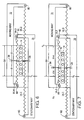
- Fig. 6 is a schematic illustration of the relationship of the ways, the cage and the four springs.
- Fig. 7 is also a schematic illustration of the relationship of the ways, the cage and the four springs.
- Fig. 1 is a schematic illustration of the improved linear bearing assembly of this invention, denoted as 10, with a cage 12 containing a plurality of rolling elements (ball bearings) 14 and four resilient elements (coil springs) 16.
- One end of each spring 16 is anchored centrally to the cage 12 by pins 20 and the other end of each spring 16 is attached to ways, denoted as S and M, representing stationary ways and movable ways, respectively.
- This illustration also shows how the cage is subjected to four springs while the stationary and movable ways are subjected to only two springs.
- Figs. 2-7 illustrate one application of this invention in an X-Y table of a particle or electron beam lithography (EBL) machine but it should be understood that this invention may be used wherever cage migration is a problem.
- EBL electron beam lithography
- FIG. 2 schematically illustrates an EBL machine 30 for processing a workpiece 32, also called a substrate, such as a semiconductor wafer or a mask.
- the workpiece 32 is supported on a chuck (not shown) and is held in position on a movable stage 34 which is translated in the X and Y directions by an X-Y drive system and the position of the stage is sensed by position sensors, typically interferometers, all of which are represented by a block diagram 36.
- the complete EBL machine 30 includes, among other things, a beam source 40 for beam 42, a central tube 44 (shown in phantom) within a beam column 46 and maintained by a high vacuum pump 50 coupled to the beam column 46.
- the beam 42 passes through an opening 52 in the beam column 46 and impinges on the workpiece 32.
- the EBL machine further includes, among other things, a controller and associated electronics which controls the beam, an X-Y drive system, a substrate handling system and means for storing pattern data and provides beam control signals, all represented by block 54.
- the X-Y table 34 includes a base 60 which includes a first lower stationary plate (stage) 62 supported on the base 60, a second middle movable plate (stage) 64, spaced from said first stage 62 and providing movement in one direction, such as in the Y direction, and a third movable top plate (stage) 66 spaced from the second stage 64 which provides movement in the direction orthogonal to the second stage 64, such as in the X direction.
- the top stage 66 is thus movable in both the X and Y directions.
- Each bearing assembly 10 includes a stationary way 70 (S in Fig. 1) and a movable way 72 (M in Fig. 1) with ball bearings 14 contained within cage 12 for anti-frictional movement between stages.
- each way 70,72 is connected to the stages 44-46 in any suitable manner, as by bolts 74, and each way is spaced apart to accommodate the cage 12 and ball bearings 14.
- Each way is also provided with grooves 76 facing one another to provide the guidance and rolling capability for the ball bearings.
- Fig. 5 also shows one end of one spring 16.3 attached to one way by pin 80 and to cage 12 as at 20 and the other end of another spring 16.2 attached to the other way by pin 82 and to cage 12 as at 20.
- Figs. 6 and 7 show the relationship between the springs 16.1 - 16.4 and ways 70,72 and the centrally located pins 20 for connecting the springs to the ball cage 12.
- Fig. 6 the cage is shown in a no drift position.
- the four springs in this view are identified as springs 16.1 - 16.4 for clarity.
- This Fig. 6 shows that springs 16.1 and 16.2 are stretched with an initial stretch of +d and the spring forces are canceled out and springs 16.3 and 16.4 have an initial stretch of -d and the spring forces cancel out.
- Fig. 7 the cage 12 has migrated to the left by an amount e (arbitrarily chosen for illustration).
- e arbitrarily chosen for illustration
- the spring forces are not canceled out but a restoring force Pe in the right direction (as shown in the drawing) is required at the moving way. This restoring force is equal to 4ek, where k is the individual spring constant.
- this invention provides for the reduction or elimination of migration of the rolling elements to assure precise positioning between a movable part and a stationary part, for example, in the X and Y stages of an X-Y stage of a EBL machine where movement of such stages is a step-by-step process and the distances are submicron.
- the restoring force applied to the cage is 4ke where k is the individual spring rate and e is the migration distance on a carefully built 15,24cm (6 inches) stage.
Landscapes
- Engineering & Computer Science (AREA)
- General Engineering & Computer Science (AREA)
- Mechanical Engineering (AREA)
- Chemical & Material Sciences (AREA)
- Analytical Chemistry (AREA)
- Bearings For Parts Moving Linearly (AREA)
- Container, Conveyance, Adherence, Positioning, Of Wafer (AREA)
- Exposure And Positioning Against Photoresist Photosensitive Materials (AREA)
- Exposure Of Semiconductors, Excluding Electron Or Ion Beam Exposure (AREA)
- Electron Beam Exposure (AREA)
Description
- This invention relates to an improvement in linear bearing assemblies and is particularly directed to a means of restraining rolling element cages and rolling elements to prevent their migration away from the center position.
- In linear bearing assemblies with roller elements (rollers or ball bearings), the rolling elements tend to migrate. Migration is caused primarily by imperfections in the components, misalignment, and/or variations in the load on the rolling elements and cage.
- This may not be a problem in leadscrew or other high force drive systems as stops at the ends of the bearings will relocate the rolling elements and their cage. When it is not permissible to hit stops at the end of travel or, if the drive forces are not strong enough, to keep the rolling elements and cages in place, rack and pinions, pulleys and filaments have been used. These mechanisms are bulky and have rubbing surfaces requiring additional forces to be applied.
- When the available driving force is limited, however, another means is necessary to keep the rolling elements from migrating very far or not at all and this invention is directed toward this end. This is particularly important where movement of the apparatus is controlled to submicron distances, step-by-step, as in an X-Y table in an inspection microscope or a particle beam machine for making semiconductor wafers and masks.
- The following prior art documents are considered as relevant for the present invention.
- DE-A-3 637 955 discloses a linear bearing assembly according to the preamble of claim 1 comprising a stationary part having two ends, a movable part having two ends, ball-shaped rollers constrained in a cage between the stationary and the movable part and two springs, one connected between one end of the stationary part and the facing end of the cage and the other connecting the opposite end of the cage and the accordingly facing end of the movable part.
- US-A-4,262,974 discloses a linear bearing apparatus for XY-tables of precision devices in Figures 4 and 5 therein, comprising a stationary part and a movable part, rollers constrained in a cage and two springs with one spring connected between one end of the stationary part and the facing end of the cage and the other spring being connected between the opposite end of the cage and the accordingly facing end of the stationary part.
- It is therefore an object of this invention to improve linear bearing assemblies by providing a means for reducing or preventing migration of the rolling elements.
- Another object of this invention is to provide a means in a linear bearing assembly which reduces or prevents migration of the rolling elements without providing bulk and without rubbing surfaces which require additional forces to be applied to overcome the friction of the rubbing surfaces.
- Another object of this invention is to improve an X-Y table for a particle beam machine for precise positioning of the top surface of the table which is critical to the proper operation of the particle beam machine.
- The foregoing objects are solved according to the invention with a linear bearing assembly according to claim 1, and the use of such a linear bearing assembly in a lithography machine as defined in claim 4.
- The improved linear bearing assembly which meets the foregoing objects comprises sets of guides (ways) for guiding rolling elements (ball bearings or rollers) constrained within a cage. Typically, two sets of rolling elements and cages are used between a moving part and a stationary part and each set has four resilient elements (springs) with one end of each spring anchored to the cage and with the other ends of two springs anchored to the stationary way or part and the other ends of the other two springs are anchored to the movable way or part. This arrangement provides a restoring spring force that gradually forces the cage in its correct tracking position. If the cage is tracking properly, the spring forces cancel out and there is no inherent rubbing to the restoring mechanism. With this arrangement, also, there are no other sliding or rubbing components which would otherwise require additional driving forces.
- At the heart of the invention is the fact that the restoring force applied to the cage and balls can be very small compared to the force required to push the balls for a long distance along the raceway. When shifting the ball and cage, it is not necessary to overcome the friction forces due to preload and weight of the stage. Instead, a force is applied to the cage very lightly but continuously. These minute forces however, are enough to change the rolling pattern at the interface of the balls and raceway and the whole cage and ball complement are kept nearly on track.
- Fig. 1 is a schematic illustration of the improved linear bearing assembly or this invention.
- Fig. 2 is a schematic illustration of an EBL machine in which the present invention is incorporated.
- Fig. 3 is an exploded view of the X-Y table of Fig. 2.
- Fig. 4 is an elevational view, partially in section showing the relationship of the stages and linear bearing assemblies.
- Fig. 5 is an enlarged view of the area encircled in Fig. 4.
- Fig. 6 is a schematic illustration of the relationship of the ways, the cage and the four springs.
- Fig. 7 is also a schematic illustration of the relationship of the ways, the cage and the four springs.
- Fig. 1 is a schematic illustration of the improved linear bearing assembly of this invention, denoted as 10, with a
cage 12 containing a plurality of rolling elements (ball bearings) 14 and four resilient elements (coil springs) 16. One end of eachspring 16 is anchored centrally to thecage 12 bypins 20 and the other end of eachspring 16 is attached to ways, denoted as S and M, representing stationary ways and movable ways, respectively. This illustration also shows how the cage is subjected to four springs while the stationary and movable ways are subjected to only two springs. - Figs. 2-7 illustrate one application of this invention in an X-Y table of a particle or electron beam lithography (EBL) machine but it should be understood that this invention may be used wherever cage migration is a problem.
- Thus, Fig. 2 schematically illustrates an
EBL machine 30 for processing aworkpiece 32, also called a substrate, such as a semiconductor wafer or a mask. Theworkpiece 32 is supported on a chuck (not shown) and is held in position on amovable stage 34 which is translated in the X and Y directions by an X-Y drive system and the position of the stage is sensed by position sensors, typically interferometers, all of which are represented by a block diagram 36. Thecomplete EBL machine 30 includes, among other things, abeam source 40 forbeam 42, a central tube 44 (shown in phantom) within abeam column 46 and maintained by ahigh vacuum pump 50 coupled to thebeam column 46. Thebeam 42 passes through anopening 52 in thebeam column 46 and impinges on theworkpiece 32. The EBL machine further includes, among other things, a controller and associated electronics which controls the beam, an X-Y drive system, a substrate handling system and means for storing pattern data and provides beam control signals, all represented byblock 54. - As shown in Figs. 3-5, the X-Y table 34 includes a
base 60 which includes a first lower stationary plate (stage) 62 supported on thebase 60, a second middle movable plate (stage) 64, spaced from saidfirst stage 62 and providing movement in one direction, such as in the Y direction, and a third movable top plate (stage) 66 spaced from thesecond stage 64 which provides movement in the direction orthogonal to thesecond stage 64, such as in the X direction. Thetop stage 66 is thus movable in both the X and Y directions. - For orthogonal movement of
stages linear bearing assemblies 10 betweenstages stages assemblies 10 oriented orthogonally. Eachbearing assembly 10 includes a stationary way 70 (S in Fig. 1) and a movable way 72 (M in Fig. 1) withball bearings 14 contained withincage 12 for anti-frictional movement between stages. - As shown in Figs. 4, and 5, each
way bolts 74, and each way is spaced apart to accommodate thecage 12 andball bearings 14. Each way is also provided withgrooves 76 facing one another to provide the guidance and rolling capability for the ball bearings. Fig. 5 also shows one end of one spring 16.3 attached to one way bypin 80 and to cage 12 as at 20 and the other end of another spring 16.2 attached to the other way bypin 82 and to cage 12 as at 20. - Figs. 6 and 7 show the relationship between the springs 16.1 - 16.4 and
ways pins 20 for connecting the springs to theball cage 12. - In Fig. 6, the cage is shown in a no drift position. The four springs in this view are identified as springs 16.1 - 16.4 for clarity. This Fig. 6 shows that springs 16.1 and 16.2 are stretched with an initial stretch of +d and the spring forces are canceled out and springs 16.3 and 16.4 have an initial stretch of -d and the spring forces cancel out. In Fig. 7, the
cage 12 has migrated to the left by an amount e (arbitrarily chosen for illustration). In this view, the spring forces are not canceled out but a restoring force Pe in the right direction (as shown in the drawing) is required at the moving way. This restoring force is equal to 4ek, where k is the individual spring constant. - Again, when forces to be applied to the ways for movement is limited and the distance of such movement being at the submicron level, it can be appreciated that this invention provides for the reduction or elimination of migration of the rolling elements to assure precise positioning between a movable part and a stationary part, for example, in the X and Y stages of an X-Y stage of a EBL machine where movement of such stages is a step-by-step process and the distances are submicron.
- With the spring arrangement shown in Figs. 5-7, the restoring force applied to the cage is 4ke where k is the individual spring rate and e is the migration distance on a carefully built 15,24cm (6 inches) stage.
- In a system without springs, the cage migrated between 1.8 x 10⁻⁷ and 9.6 x 10⁻⁷mm per each mm (inches per each inch) of stage travel. This represents up to 1.47cm (0.58 inch). migration/100,000 cycles, an unacceptable value. By applying a force to the cages in this system, it was determined that the cage moved at the rate of 1,2 x 10⁻⁴ mm/mm stage travel for each Newton of applied force (5.3 x 10⁻⁴ inches/inch stage travel for each pound of applied force). This means that the forces inducing migration are equivalent to:

A system built with four springs of 3.3 x 10⁻³ N/mm (.019 lb/inch) would apply a restoring force of 4 x 3.3 x 10⁻³ N/mm (.019 lb/inch) migration. Migration in this system would be limited to:
In the case of a less precisely built stage with 10 times more intrinsic migration. The cage would never migrate beyond 6.1 mm (.24 inches), still an acceptable value. - Finally, while the above described preferred embodiment utilizes four springs, other combinations of springs are feasible. For example, two springs coupled to the ways and the cage as taught above may be used and, similarly, eight springs attached as taught above may be used. The use of four springs provides a preferred balance of all of the forces.
Claims (4)
- A linear bearing assembly (10) comprising
a stationary part (70) having two ends,
a movable part (72) having two ends, a sliding component comprising rolling elements (14) constrained in a cage (12) permitting parallel displacement of said moveable part (72) in juxtaposition to said stationary part (70), and
resilient means for reducing or eliminating migration of the rolling elements comprising a first resilient element (16.1) and a second resilient element (16.2), the said first resilient element (16.1) having a first end affixed to a first end of the stationary part (70) and said second end affixed to the sliding component and said second resilient element (16.2) having a first end affixed to the sliding component and the second end affixed to the first end of the movable part, characterised in that the resilient means further comprise a third resilient element (16.3) and a fourth resilient element (16.4), wherein the third resilient element (16.3) has a first end affixed to the sliding component and the second end affixed to the second end of said stationary part and the fourth resilient element (16.4) has a first end affixed to the sliding component and a second end affixed to the second end of said movable part (72). - The linear bearing assembly as claimed in claim 1 wherein the rolling elements are guided by ways (70,72).
- The linear bearing assembly as claimed in claim 1, wherein the resilient elements are coil springs.
- The use of a linear bearing assembly (10) according to claims 1 to 3 in a lithography machine wherein a particle beam is directed through a beam column (46) and onto a substrate (32) and having a magnetic deflection assembly for positioning the beam within a field of a selected size and having an X-Y table (34) for holding the substrate (32) and moving the substrate (32) in an X and Y direction, wherein said X-Y table comprises a first stage (62) and a second stage (64) movable in a first direction, and a third stage (66) movable with respect to the second stage (64) in a second direction orthogonal to said first direction, with the linear bearing assemblies (10) according to one of the claims 1 to 3 being positioned between said first and second stages and said second and third stages.
Applications Claiming Priority (2)
| Application Number | Priority Date | Filing Date | Title |
|---|---|---|---|
| US07/713,929 US5180230A (en) | 1991-06-12 | 1991-06-12 | Rolling element cage constraint |
| US713929 | 1991-06-12 |
Publications (2)
| Publication Number | Publication Date |
|---|---|
| EP0518372A1 EP0518372A1 (en) | 1992-12-16 |
| EP0518372B1 true EP0518372B1 (en) | 1995-12-27 |
Family
ID=24868117
Family Applications (1)
| Application Number | Title | Priority Date | Filing Date |
|---|---|---|---|
| EP92109949A Expired - Lifetime EP0518372B1 (en) | 1991-06-12 | 1992-06-12 | Rolling element cage constraint |
Country Status (5)
| Country | Link |
|---|---|
| US (1) | US5180230A (en) |
| EP (1) | EP0518372B1 (en) |
| JP (1) | JPH05217874A (en) |
| CA (1) | CA2071085C (en) |
| DE (2) | DE518372T1 (en) |
Families Citing this family (10)
| Publication number | Priority date | Publication date | Assignee | Title |
|---|---|---|---|---|
| JP3455016B2 (en) * | 1996-06-20 | 2003-10-06 | シグマ光機株式会社 | Method and apparatus for machining steel ball guide groove on linear motion stage |
| JP3077605B2 (en) * | 1996-10-18 | 2000-08-14 | 日新電機株式会社 | Holder drive |
| TWI242112B (en) * | 1999-04-19 | 2005-10-21 | Asml Netherlands Bv | Lithographic projection apparatus and method of operating a lithographic projection apparatus |
| NL1013116C2 (en) * | 1999-09-22 | 2001-04-03 | Onstream B V | Legal guidance. |
| JP2004028329A (en) * | 2003-03-28 | 2004-01-29 | Sigma Koki Kk | Linear motion stage |
| WO2013039387A1 (en) * | 2011-09-12 | 2013-03-21 | Mapper Lithography Ip B.V. | Guidance for target processing tool |
| WO2019193759A1 (en) * | 2018-04-06 | 2019-10-10 | オリンパス株式会社 | Slide actuator |
| CN209380278U (en) * | 2018-12-07 | 2019-09-13 | 惠州迪芬尼声学科技股份有限公司 | A kind of slide rail |
| WO2020179018A1 (en) * | 2019-03-06 | 2020-09-10 | オリンパス株式会社 | Slide actuator |
| WO2021102295A1 (en) * | 2019-11-21 | 2021-05-27 | Thomas Baer | Systems and methods for detecting running and walking strides and foot strikes |
Family Cites Families (10)
| Publication number | Priority date | Publication date | Assignee | Title |
|---|---|---|---|---|
| DE1065748B (en) * | 1957-09-14 | 1959-09-17 | Robert Blohm, Hamburg-Bergedorf | Rolling bearings for tool tables, in particular grinding machine tables |
| US3563617A (en) * | 1969-06-09 | 1971-02-16 | James L Pritchard | Antifriction |
| SU750161A1 (en) * | 1978-01-06 | 1980-07-23 | Предприятие П/Я В-2572 | Rolling-contact bearing assembly for reciprocating movement |
| JPS5551119A (en) * | 1978-10-12 | 1980-04-14 | Toshiba Corp | Linear bearing device |
| JPS5948888B2 (en) * | 1978-10-31 | 1984-11-29 | 株式会社東芝 | linear bearing |
| DE3433460A1 (en) * | 1984-08-22 | 1986-03-06 | Parke, Davis & Co., Morris Plains, N.J. | LEADERSHIP |
| JPS62155325A (en) * | 1985-12-27 | 1987-07-10 | Makino Milling Mach Co Ltd | linear bearing device |
| DE3637955A1 (en) * | 1986-11-07 | 1988-05-11 | Skf Linearsysteme Gmbh | Linear rolling bearing |
| US4974291A (en) * | 1988-09-22 | 1990-12-04 | R. J. McNerney | Shipping carton for further processing of product |
| DE4028383A1 (en) * | 1989-09-12 | 1991-03-21 | Hydrel Ag | Linear bearing with caged construction - has cage displacement sprung relative to support displacement |
-
1991
- 1991-06-12 US US07/713,929 patent/US5180230A/en not_active Expired - Lifetime
-
1992
- 1992-06-11 CA CA002071085A patent/CA2071085C/en not_active Expired - Fee Related
- 1992-06-12 DE DE199292109949T patent/DE518372T1/en active Pending
- 1992-06-12 DE DE69207074T patent/DE69207074T2/en not_active Expired - Fee Related
- 1992-06-12 JP JP4177763A patent/JPH05217874A/en active Pending
- 1992-06-12 EP EP92109949A patent/EP0518372B1/en not_active Expired - Lifetime
Also Published As
| Publication number | Publication date |
|---|---|
| DE69207074D1 (en) | 1996-02-08 |
| DE518372T1 (en) | 1993-07-22 |
| JPH05217874A (en) | 1993-08-27 |
| CA2071085C (en) | 1998-11-24 |
| CA2071085A1 (en) | 1992-12-13 |
| DE69207074T2 (en) | 1996-05-15 |
| EP0518372A1 (en) | 1992-12-16 |
| US5180230A (en) | 1993-01-19 |
Similar Documents
| Publication | Publication Date | Title |
|---|---|---|
| US5760564A (en) | Dual guide beam stage mechanism with yaw control | |
| US4648725A (en) | Guide mechanism | |
| EP0017144A1 (en) | An apparatus for precisely moving a table | |
| US4358198A (en) | Apparatus for moving table on stage | |
| EP0196711B1 (en) | A positioning device comprising pre-stressed contactless bearings | |
| US5180230A (en) | Rolling element cage constraint | |
| US4262974A (en) | Linear bearing apparatus | |
| EP1189018B1 (en) | Six axes positioning system with a space free from magnetic field | |
| GB2133930A (en) | Workpiece carriages | |
| US5314254A (en) | Stiffness enhancer for movable stage assembly | |
| IL109285A (en) | Lens assembly with permanent magnetic suspension with roller guides | |
| JPS6320014B2 (en) | ||
| US10663040B2 (en) | Method and precision nanopositioning apparatus with compact vertical and horizontal linear nanopositioning flexure stages for implementing enhanced nanopositioning performance | |
| US6781138B2 (en) | Positioning stage with stationary actuators | |
| US6947125B2 (en) | Bearing arrangement for reaction mass in a controlled environment | |
| US4157818A (en) | X-Y Movable work holder | |
| JPH0760581A (en) | XY stage | |
| US5561299A (en) | X-Y stage and charged particle beam exposure apparatus | |
| EP4468330A1 (en) | Passive gravity compensator for semiconductor equipment | |
| US20050186064A1 (en) | Positioning apparatus and exposure apparatus | |
| JPH06163359A (en) | Precision positioning device | |
| US20250198488A1 (en) | Guidance system | |
| JPH05118326A (en) | Flat surface rolling guide mechanism | |
| JPH10294264A (en) | Electron beam drawing equipment | |
| JPH0737791A (en) | Stage guidance device |
Legal Events
| Date | Code | Title | Description |
|---|---|---|---|
| PUAI | Public reference made under article 153(3) epc to a published international application that has entered the european phase |
Free format text: ORIGINAL CODE: 0009012 |
|
| AK | Designated contracting states |
Kind code of ref document: A1 Designated state(s): DE FR GB IT NL |
|
| ITCL | It: translation for ep claims filed |
Representative=s name: G.PETRAZ P.SSO GLP S.R.L. |
|
| EL | Fr: translation of claims filed | ||
| TCNL | Nl: translation of patent claims filed | ||
| 17P | Request for examination filed |
Effective date: 19930426 |
|
| DET | De: translation of patent claims | ||
| 17Q | First examination report despatched |
Effective date: 19931217 |
|
| GRAA | (expected) grant |
Free format text: ORIGINAL CODE: 0009210 |
|
| ITF | It: translation for a ep patent filed | ||
| AK | Designated contracting states |
Kind code of ref document: B1 Designated state(s): DE FR GB IT NL |
|
| REF | Corresponds to: |
Ref document number: 69207074 Country of ref document: DE Date of ref document: 19960208 |
|
| ET | Fr: translation filed | ||
| PLBE | No opposition filed within time limit |
Free format text: ORIGINAL CODE: 0009261 |
|
| STAA | Information on the status of an ep patent application or granted ep patent |
Free format text: STATUS: NO OPPOSITION FILED WITHIN TIME LIMIT |
|
| 26N | No opposition filed | ||
| PGFP | Annual fee paid to national office [announced via postgrant information from national office to epo] |
Ref country code: FR Payment date: 19980520 Year of fee payment: 7 |
|
| PG25 | Lapsed in a contracting state [announced via postgrant information from national office to epo] |
Ref country code: FR Free format text: THE PATENT HAS BEEN ANNULLED BY A DECISION OF A NATIONAL AUTHORITY Effective date: 19990630 |
|
| REG | Reference to a national code |
Ref country code: FR Ref legal event code: ST |
|
| PGFP | Annual fee paid to national office [announced via postgrant information from national office to epo] |
Ref country code: GB Payment date: 20010625 Year of fee payment: 10 |
|
| PGFP | Annual fee paid to national office [announced via postgrant information from national office to epo] |
Ref country code: NL Payment date: 20010628 Year of fee payment: 10 |
|
| PGFP | Annual fee paid to national office [announced via postgrant information from national office to epo] |
Ref country code: DE Payment date: 20010726 Year of fee payment: 10 |
|
| REG | Reference to a national code |
Ref country code: GB Ref legal event code: IF02 |
|
| PG25 | Lapsed in a contracting state [announced via postgrant information from national office to epo] |
Ref country code: GB Free format text: LAPSE BECAUSE OF NON-PAYMENT OF DUE FEES Effective date: 20020612 |
|
| PG25 | Lapsed in a contracting state [announced via postgrant information from national office to epo] |
Ref country code: NL Free format text: LAPSE BECAUSE OF NON-PAYMENT OF DUE FEES Effective date: 20030101 Ref country code: DE Free format text: LAPSE BECAUSE OF NON-PAYMENT OF DUE FEES Effective date: 20030101 |
|
| GBPC | Gb: european patent ceased through non-payment of renewal fee |
Effective date: 20020612 |
|
| NLV4 | Nl: lapsed or anulled due to non-payment of the annual fee |
Effective date: 20030101 |
|
| REG | Reference to a national code |
Ref country code: GB Ref legal event code: 732E |
|
| PG25 | Lapsed in a contracting state [announced via postgrant information from national office to epo] |
Ref country code: IT Free format text: LAPSE BECAUSE OF NON-PAYMENT OF DUE FEES;WARNING: LAPSES OF ITALIAN PATENTS WITH EFFECTIVE DATE BEFORE 2007 MAY HAVE OCCURRED AT ANY TIME BEFORE 2007. THE CORRECT EFFECTIVE DATE MAY BE DIFFERENT FROM THE ONE RECORDED. Effective date: 20050612 |