EP0518167A1 - Vehicle - Google Patents
Vehicle Download PDFInfo
- Publication number
- EP0518167A1 EP0518167A1 EP92109232A EP92109232A EP0518167A1 EP 0518167 A1 EP0518167 A1 EP 0518167A1 EP 92109232 A EP92109232 A EP 92109232A EP 92109232 A EP92109232 A EP 92109232A EP 0518167 A1 EP0518167 A1 EP 0518167A1
- Authority
- EP
- European Patent Office
- Prior art keywords
- drive
- drive shaft
- housing
- final
- vehicle according
- Prior art date
- Legal status (The legal status is an assumption and is not a legal conclusion. Google has not performed a legal analysis and makes no representation as to the accuracy of the status listed.)
- Granted
Links
Images


Classifications
-
- A—HUMAN NECESSITIES
- A01—AGRICULTURE; FORESTRY; ANIMAL HUSBANDRY; HUNTING; TRAPPING; FISHING
- A01D—HARVESTING; MOWING
- A01D69/00—Driving mechanisms or parts thereof for harvesters or mowers
-
- B—PERFORMING OPERATIONS; TRANSPORTING
- B60—VEHICLES IN GENERAL
- B60K—ARRANGEMENT OR MOUNTING OF PROPULSION UNITS OR OF TRANSMISSIONS IN VEHICLES; ARRANGEMENT OR MOUNTING OF PLURAL DIVERSE PRIME-MOVERS IN VEHICLES; AUXILIARY DRIVES FOR VEHICLES; INSTRUMENTATION OR DASHBOARDS FOR VEHICLES; ARRANGEMENTS IN CONNECTION WITH COOLING, AIR INTAKE, GAS EXHAUST OR FUEL SUPPLY OF PROPULSION UNITS IN VEHICLES
- B60K17/00—Arrangement or mounting of transmissions in vehicles
-
- Y—GENERAL TAGGING OF NEW TECHNOLOGICAL DEVELOPMENTS; GENERAL TAGGING OF CROSS-SECTIONAL TECHNOLOGIES SPANNING OVER SEVERAL SECTIONS OF THE IPC; TECHNICAL SUBJECTS COVERED BY FORMER USPC CROSS-REFERENCE ART COLLECTIONS [XRACs] AND DIGESTS
- Y10—TECHNICAL SUBJECTS COVERED BY FORMER USPC
- Y10S—TECHNICAL SUBJECTS COVERED BY FORMER USPC CROSS-REFERENCE ART COLLECTIONS [XRACs] AND DIGESTS
- Y10S180/00—Motor vehicles
- Y10S180/90—Argicultural-type tractors
-
- Y—GENERAL TAGGING OF NEW TECHNOLOGICAL DEVELOPMENTS; GENERAL TAGGING OF CROSS-SECTIONAL TECHNOLOGIES SPANNING OVER SEVERAL SECTIONS OF THE IPC; TECHNICAL SUBJECTS COVERED BY FORMER USPC CROSS-REFERENCE ART COLLECTIONS [XRACs] AND DIGESTS
- Y10—TECHNICAL SUBJECTS COVERED BY FORMER USPC
- Y10S—TECHNICAL SUBJECTS COVERED BY FORMER USPC CROSS-REFERENCE ART COLLECTIONS [XRACs] AND DIGESTS
- Y10S180/00—Motor vehicles
- Y10S180/905—Axles
-
- Y—GENERAL TAGGING OF NEW TECHNOLOGICAL DEVELOPMENTS; GENERAL TAGGING OF CROSS-SECTIONAL TECHNOLOGIES SPANNING OVER SEVERAL SECTIONS OF THE IPC; TECHNICAL SUBJECTS COVERED BY FORMER USPC CROSS-REFERENCE ART COLLECTIONS [XRACs] AND DIGESTS
- Y10—TECHNICAL SUBJECTS COVERED BY FORMER USPC
- Y10S—TECHNICAL SUBJECTS COVERED BY FORMER USPC CROSS-REFERENCE ART COLLECTIONS [XRACs] AND DIGESTS
- Y10S56/00—Harvesters
- Y10S56/06—Clutches and gearing
-
- Y—GENERAL TAGGING OF NEW TECHNOLOGICAL DEVELOPMENTS; GENERAL TAGGING OF CROSS-SECTIONAL TECHNOLOGIES SPANNING OVER SEVERAL SECTIONS OF THE IPC; TECHNICAL SUBJECTS COVERED BY FORMER USPC CROSS-REFERENCE ART COLLECTIONS [XRACs] AND DIGESTS
- Y10—TECHNICAL SUBJECTS COVERED BY FORMER USPC
- Y10T—TECHNICAL SUBJECTS COVERED BY FORMER US CLASSIFICATION
- Y10T74/00—Machine element or mechanism
- Y10T74/21—Elements
- Y10T74/2186—Gear casings
Definitions
- the invention relates to a vehicle with a transverse final drive housing, by means of which rear wheels can be driven, with a motor which has a drive shaft which emerges at the bottom and is arranged essentially vertically, and with a relative movement which is vertical relative to the vehicle and is carried out from the drive shaft a belt drive driven implement.
- the object to be achieved with the invention is seen in placing the drive shaft of the engine, which may be identical to its crankshaft, as close as possible to the final gear.
- This object has been achieved according to the invention in that the motor is arranged above the final drive housing and the final drive housing is recessed in its region lying at the front with respect to the longitudinal direction of the vehicle for receiving parts which are directly or indirectly connected to the drive shaft.
- the drive shaft can be moved far back and the motor with its center of gravity almost via the final transmission, so that moments acting on the frame of the vehicle are low.
- the frame can therefore be made lighter. Moving the drive shaft back results in a sufficient belt length with large height components, particularly for devices suspended between the vehicle axles but also for devices suspended from the front.
- the center of gravity of the motor can also be lowered, which improves the stability of the vehicle.
- An essential aspect is also seen in the fact that a pulley can be arranged on the drive shaft so that the drive belt runs in the ideal horizontal plane.
- a recessed area can be easily integrated into the final drive housing according to the invention in that the final drive housing has an off-center differential in its front region with drive axles emerging laterally from the final drive housing and in that the recessed area in front of one of the drive axles and laterally next to the differential is provided. This even gives the drive shaft the possibility that it can be provided centrally in front of the final drive housing.
- the recessed area can be concentric with the drive shaft. This results in a segment-like section.
- a drive disk seated on the drive shaft can be at least partially accommodated in the recessed area of the final drive housing located at the front.
- Such a drive pulley would be connected to a device-side pulley via a belt drive, the length of the drive shaft permitting the drive pulley to be arranged such that the belt runs in a substantially horizontal plane.
- a coupling is arranged on the drive shaft, which is releasably connected to the final drive housing via fastening means.
- Another inventive measure provides that the drive pulley is arranged above the clutch on the drive shaft, the clutch housing can be rotated on the drive shaft after loosening its fastening means and that a gap allowing the removal of the belt is provided between the clutch and the final drive housing. The gap released by turning the clutch housing allows all belt drives driven by the drive shaft to be removed.
- a further pulley can be provided above the drive pulley.
- the drive pulley can be connected in a rotationally fixed manner to the drive shaft via the coupling, which can be actuated electrically.
- the additional pulley is then usually mounted on the drive shaft so that it cannot rotate.
- the drive pulley can also be provided on the drive shaft below the clutch. If a clutch is not required, the drive shaft can be arranged even further backwards in such a case.
- a rearward of the differential is provided in the final drive housing, a manual transmission which can be driven from the drive shaft via a belt drive.
- the engine and transmission can then be designed as separate structural units with the further advantage that both units are balanced in the assembled state with respect to the drive axles. In such a case, the vehicle frame need not absorb any or almost no moments.
- a vehicle 10 for lawn care is partially shown. Front and rear wheels, one The steering device and a seat are not shown.
- the vehicle 10 has a frame 12, a motor 14 arranged at the rear end of the frame 12, an end gear 16 and a mower housing 18 with a mower.
- a belt 20 connects a drive shaft 22 of the motor 14 via a drive pulley 24 provided on the drive shaft to a driven pulley 26 which drives the mower.
- On the drive shaft 22 of the motor 14 a further pulley 28 is non-rotatably arranged, which in turn is connected via a second belt 30 to a pulley 32 via which the power flow from the motor to the final transmission 16 can be transmitted.
- the drive shaft 22 of the motor 14 arranged at the rear extends downward or downward and is equipped with an electrically operable clutch 34.
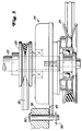
- This can be arranged above the drive pulley 24, as indicated in FIG. 5, or below the drive pulley 24, as shown in FIG. 6.
- the clutch 34 has moved as close as possible to the final gear 16, which is provided with a recess 36 or opening for this purpose, which can be seen particularly well from FIGS. 2 and 3.
- a differential 40 of the final drive 16 was laterally offset, so that the recess 36 can be located directly next to the differential 40 in the final drive housing 38.
- the final drive housing 38 namely in the rear area behind the differential 40, there is also a conventional manual transmission 42, for which reference is also made to the illustration in FIG. 3.
- the differential 40 is also provided with a right and a left drive axle 44 on which the drivable wheels of the vehicle, not shown, are seated.
- the differential 40 in the final drive housing 38 is arranged at the front and offset to one side from the center, the space for the drive disk 24 and / or the clutch 34 was created in the front region of the final drive housing 38.
- This arrangement also allows the motor to lie with its center of gravity more or less above the drive axles 44, so that the motor weight is directly on the drivable Wheels can be transmitted and significant parts of the weight are not directed into the vehicle body.
- this arrangement allows the motor to be mounted very low or in a lower position on the frame 12, which improves the stability of the vehicle.
- the endless belt 20 is pulled around the drive pulley 24 and the driven pulley 26 and can be tensioned by a spring-loaded tension roller 46.
- the second endless belt 30 connects the further pulley 28 on the drive shaft 22 with the pulley 36 on the final transmission 16.
- This belt is also tensioned by a spring-loaded idler pulley, which can also interrupt the drive connection and thus acts as a clutch for the final transmission.
- the drive shaft 22 with its pulleys and the clutch 34 is shown on an enlarged scale.
- the drive pulley 24 is shown once above the clutch 34 (FIG. 6) and once below the clutch 34 (FIG. 5).
- the coupling housing 48 is detachably connected to the final drive housing by means of fastening means, a fastening means 50 comprising a pin 50 and a linch pin 52.
- the clutch housing 48 accommodates a conventional and electrically actuable clutch 34, via which the drive disk 24 can optionally be connected in a rotationally fixed manner to the drive shaft 22.
- the clutch housing is arranged in a stationary manner by the fastening means and, depending on whether the clutch is activated or not, the drive disk 24 rotates with the drive shaft 22 or not.
- Pulley 28 is rotatably arranged on the drive shaft 22 and therefore constantly rotates with it when the engine is running.
- the drive pulley 24 is arranged above the clutch 34 and thus at a higher level. This embodiment is preferred if the driven pulley 26 is arranged higher.
- annular gap 62 between the final drive housing 38 and the clutch housing 48.
- Such an annular gap is also located between the final drive housing and the drive disk 24 when it is arranged above the clutch 34.
- the annular gap makes it possible to remove the belt 20 and possibly also the belt 30 if one of these belts has to be replaced.
- the clutch housing 48 can be rotated from its position shown in full lines in FIG. 4 to the position shown in broken lines in FIG. 4 after the linch pin 52 and the pin 50 have been removed.
- the tensioning rollers are brought into a position in which they no longer tension the belt to be replaced and the corresponding belt can be released from the drive shaft 22 by passing it through the annular gap. This makes it easy to replace the straps.
Abstract
Bei einem Fahrzeug mit einem querliegenden Endantriebsgehäuse (38), über das rückwärtige Laufräder antreibbar sind, mit einem Motor, der eine bodenwärts austretende und im wesentlichen vertikal angeordnete Antriebswelle (22) aufweist, und mit einem gegenüber dem Fahrzeug vertikale Relativbewegungen ausführenden und von der Antriebswelle (22) aus über einen Riementrieb antreibbaren Arbeitsgerät ist der Motor über dem Endantriebsgehäuse (38) angeordnet und das Endantriebsgehäuse (38) ist in seinem mit Bezug auf die Fahrzeuglängsrichtung vorn liegenden Bereich zur Aufnahme von mit der Antriebswelle (22) mittel- oder unmittelbar verbundenen Teilen ausgespart ausgebildet. <IMAGE>In a vehicle with a transverse final drive housing (38), by means of which rear wheels can be driven, with a motor which has a drive shaft (22) which emerges at the bottom and is arranged essentially vertically, and with a vertical movement relative to the vehicle and from the drive shaft (22) from a working device that can be driven via a belt drive, the motor is arranged above the final drive housing (38) and the final drive housing (38) is in its front area with respect to the vehicle longitudinal direction for receiving directly or indirectly connected to the drive shaft (22) Parts trained recessed. <IMAGE>
Description
Die Erfindung bezieht sich auf ein Fahrzeug mit einem querliegenden Endantriebsgehäuse, über das rückwärtige Laufräder antreibbar sind, mit einem Motor, der eine bodenwärts austretende und im wesentlichen vertikal angeordnete Antriebswelle aufweist, und mit einem gegenüber dem Fahrzeug vertikale Relativbewegungen ausführenden und von der Antriebswelle aus über einen Riementrieb antreibbaren Arbeitsgerät.The invention relates to a vehicle with a transverse final drive housing, by means of which rear wheels can be driven, with a motor which has a drive shaft which emerges at the bottom and is arranged essentially vertically, and with a relative movement which is vertical relative to the vehicle and is carried out from the drive shaft a belt drive driven implement.
Bei diesem bekannten Fahrzeug in Form eines Kleinschleppers (US-A-4 969 319) ist heckseitig ein Rasenmäher derartig angeschlossen, daß der Rasenmäher der Bodenkontur folgen kann, d. h. der Rasenmäher verändert mit Bezug auf den ziehenden Kleinschlepper bei auftretenden Bodenunebenheiten ständig seine Lage. Dieser Lageänderung muß der Riementrieb folgen, wodurch sich die Winkellage des Riementriebes ständig ändert. Wird die maximale Winkellage, die vom Riemenhersteller vorgegeben ist, überschritten, dann tritt zunächst zumindest übermäßiger Verschleiß auf mit der Folge, daß der Riemen beschädigt und der Antrieb unterbrochen wird. Je größer der Längenabstand von treibender Riemenscheibe zur getriebenen Riemenscheibe ist, um so größer ist die Höhenkomponente, weshalb jeder Hersteller bemüht ist, einen relativ großen Längenabstand vorzusehen. Dies ist bei den kleinen in der Rasen- und Grundstückspflege einsetzbaren Fahrzeugen oft nicht oder nur mit großen Schwierigkeiten zu bewerkstelligen, da diese Fahrzeuge häufig ein Endgetriebe aufweisen, das eine Kombination aus Differential- und Schaltgetriebe ist. Vielfach ist mit derartigen Getrieben noch der Motor verflanscht. Die treibende Riemenscheibe ist dann relativ hoch vorzusehen und die getriebene Riemenscheibe relativ niedrig, so daß ein Riementrieb sehr schnell seine maximale Winkellage überschreiten kann. Beim gattungsbildenden Dokumemt ist jedoch eine relativ große Höhenkomponente dadurch erreicht, daß der Riementrieb für den Rasenmäher unterhalb des Endgetriebes verläuft. Allerdings ist hier der Motor vor dem Endgetriebe angeordnet, so daß es bei einem Zwischenachsanbau des Gerätes sehr schnell zu einer Überschreitung der maximalen Winkellage kommen würde, wobei der Motor zusätzlich infolge seines Gewichtes ein relativ großes Moment auf den Fahrzeugrahmen ausübt und dieser deshalb relativ stabil ausgebildet werden muß. Hinzu kommt, daß es aus Wartungszwecken wünschenswert ist, daß Motor und Endgetriebe von einander unabhängige Einheiten bilden.In this known vehicle in the form of a small tractor (US-A-4 969 319), a lawn mower is connected at the rear in such a way that the lawn mower can follow the ground contour, ie the lawn mower constantly changes its position with respect to the pulling small tractor when the ground is uneven. The belt drive must follow this change in position, as a result of which the angular position of the belt drive changes constantly. If the maximum angular position specified by the belt manufacturer is exceeded, then at least excessive wear occurs, with the result that the belt is damaged and the drive is interrupted. The greater the length distance from the driving pulley to the driven pulley, the greater the height component, which is why every manufacturer endeavors to provide a relatively large length distance. This is often not possible or can only be accomplished with great difficulty in the small vehicles which can be used in lawn and property maintenance, since these vehicles often have a final transmission which is a combination of differential and manual transmission. In many cases, the motor is flanged with such gears. The driving pulley is then to be provided relatively high and the driven pulley relatively low, so that a belt drive can exceed its maximum angular position very quickly. In the generic document, however, a relatively large height component is achieved in that the belt drive for the lawn mower runs below the final drive. However, here the motor is arranged in front of the final gearbox, so that the maximum angular position would be exceeded very quickly if the device were mounted on an interaxle must be trained stably. In addition, it is desirable for maintenance purposes that the motor and final gear unit form independent units.
Die mit der Erfindung zu lösende Aufgabe wird darin gesehen, die Antriebswelle des Motors, die mit dessen Kurbelwelle identisch sein kann, so nahe wie möglich an das Endgetriebe heranzulegen. Diese Aufgabe ist nach der Erfindung dadurch gelöst worden, daß der Motor über dem Endantriebsgehäuse angeordnet ist und das Endantriebsgehäuse in seinem mit Bezug auf die Fahrzeuglängsrichtung vorn liegenden Bereich zur Aufnahme von mit der Antriebswelle mittel- oder unmittelbar verbundenen Teilen ausgespart ausgebildet ist. Auf diese Weise kann die Antriebswelle weit nach hinten verlegt werden und der Motor mit seinem Schwerpunkt fast über das Endgetriebe, so daß auf den Rahmen des Fahrzeuges einwirkende Momente gering sind. Der Rahmen kann daher leichter ausgebildet sein. Durch das Zurückversetzen der Antriebswelle ergibt sich insbesondere für zwischen den Fahrzeugachsen aufgehängte Geräte aber auch für frontseitig aufgehängte Geräte eine ausreichende Riemenlänge mit großen Höhenkomponenten. Da die mit der Antriebswelle verbindbaren Komponenten in Bereiche reichen, die sonst von dem Getriebegehäuse beansprucht werden, kann der Motor mit seinem Schwerpunkt auch tiefer gelegt werden, wodurch die Stabilität des Fahrzeuges verbessert wird. Ein wesentlicher Gesichtspunkt wird auch darin gesehen, daß eine Riemenscheibe auf der Antriebswelle so angeordnet werden kann, daß der Antriebsriemen in der idealen Horizontalebene verläuft.The object to be achieved with the invention is seen in placing the drive shaft of the engine, which may be identical to its crankshaft, as close as possible to the final gear. This object has been achieved according to the invention in that the motor is arranged above the final drive housing and the final drive housing is recessed in its region lying at the front with respect to the longitudinal direction of the vehicle for receiving parts which are directly or indirectly connected to the drive shaft. In this way, the drive shaft can be moved far back and the motor with its center of gravity almost via the final transmission, so that moments acting on the frame of the vehicle are low. The frame can therefore be made lighter. Moving the drive shaft back results in a sufficient belt length with large height components, particularly for devices suspended between the vehicle axles but also for devices suspended from the front. Since the components that can be connected to the drive shaft extend into areas that would otherwise be used by the gearbox, the center of gravity of the motor can also be lowered, which improves the stability of the vehicle. An essential aspect is also seen in the fact that a pulley can be arranged on the drive shaft so that the drive belt runs in the ideal horizontal plane.
Ein ausgesparter Bereich läßt sich nach der Erfindung leicht dadurch in das Endantriebsgehäuse integrieren, daß das Endantriebsgehäuse in seinem vorn liegenden Bereich ein außer mittig angeordnetes Differential mit seitlich aus dem Endantriebsgehäuse austretenden Antriebsachsen aufweist und daß der ausgesparte Bereich vor einer der Antriebsachsen und seitlich neben dem Differential vorgesehen ist. Dies gibt der Antriebswelle sogar die Möglichkeit, daß sie mittig vor dem Endantriebsgehäuse vorgesehen werden kann.A recessed area can be easily integrated into the final drive housing according to the invention in that the final drive housing has an off-center differential in its front region with drive axles emerging laterally from the final drive housing and in that the recessed area in front of one of the drive axles and laterally next to the differential is provided. This even gives the drive shaft the possibility that it can be provided centrally in front of the final drive housing.
Damit die Materialstärke des Endantriebsgehäuses vor der Antriebsachse durch den ausgesparten Bereich nicht zu stark reduziert wird, kann der ausgesparte Bereich zur Antriebswelle konzentrisch ausgebildet sein. Hierdurch ergibt sich ein segmentartiger Ausschnitt.So that the material thickness of the final drive housing in front of the drive axle is not reduced too much by the recessed area, the recessed area can be concentric with the drive shaft. This results in a segment-like section.
Nach einem weiteren Vorschlag der Erfindung kann in dem vorn liegenden ausgesparten Bereich des Endantriebsgehäuses eine auf der Antriebswelle aufsitzende Antriebsscheibe zumindest teilweise aufgenommen werden. Eine solche Antriebsscheibe wäre über einen Riementrieb mit einer geräteseitigen Riemenscheibe zu verbinden, wobei die Länge der Antriebswelle es zuläßt, die Antriebsscheibe so anzuordnen, daß der Riemen in einer im wesentlichen horizontalen Ebene verläuft.According to a further proposal of the invention, a drive disk seated on the drive shaft can be at least partially accommodated in the recessed area of the final drive housing located at the front. Such a drive pulley would be connected to a device-side pulley via a belt drive, the length of the drive shaft permitting the drive pulley to be arranged such that the belt runs in a substantially horizontal plane.
Von Vorteil kann es außerdem sein, daß in dem ausgesparten Bereich des Endantriebsgehäuses eine auf der Antriebswelle angeordnete Kupplung aufgenommen ist, die mit dem Endantriebsgehäuse über Befestigungsmittel lösbar verbunden ist. Hierdurch kann bei laufendem Motor ein Riementrieb abgeschaltet werden, was bei bestimmten Einsatzverhältnissen vorteilhaft sein kann.It may also be advantageous that in the recessed area of the final drive housing, a coupling is arranged on the drive shaft, which is releasably connected to the final drive housing via fastening means. As a result, a belt drive can be switched off while the engine is running, which can be advantageous in certain operating conditions.
Eine weitere erfinderische Maßnahme sieht vor, daß die Antriebsscheibe oberhalb der Kupplung auf der Antriebswelle angeordnet ist, das Kupplungsgehäuse nach Lösen deren Befestigungsmittel auf der Antriebswelle drehbar ist und daß zwischen der Kupplung und dem Endantriebsgehäuse ein das Entfernen des Riemens ermöglichender Spalt vorgesehen ist. Der durch Drehen des Kupplungsgehäuses frei werdende Spalt läßt ein Entfernen aller von der Antriebswelle aus angetrieben Riementriebe zu.Another inventive measure provides that the drive pulley is arranged above the clutch on the drive shaft, the clutch housing can be rotated on the drive shaft after loosening its fastening means and that a gap allowing the removal of the belt is provided between the clutch and the final drive housing. The gap released by turning the clutch housing allows all belt drives driven by the drive shaft to be removed.
Wenn von dem Motor noch weitere Aggregate aus angetrieben werden sollen, kann oberhalb der Antriebsscheibe eine weitere Riemenscheibe vorgesehen werden.If further units are to be driven by the engine, a further pulley can be provided above the drive pulley.
Zum Ausschalten eines Riementriebes kann die Antriebsscheibe über die Kupplung, die elektrisch betätigbar ist, mit der Antriebswelle drehfest verbindbar sein. Die weitere Riemenscheibe ist dann in der Regel drehfest auf der Antriebswelle montiert.To switch off a belt drive, the drive pulley can be connected in a rotationally fixed manner to the drive shaft via the coupling, which can be actuated electrically. The additional pulley is then usually mounted on the drive shaft so that it cannot rotate.
Wenn die Platzverhältnisse es zulassen, kann die Antriebsscheibe auf der Antriebswelle auch unterhalb der Kupplung vorgesehen sein. Wird eine Kupplung nicht benötigt, so kann in einem solchen Fall die Antriebswelle noch weiter nach rückwärts versetzt angeordnet werden.If space permits, the drive pulley can also be provided on the drive shaft below the clutch. If a clutch is not required, the drive shaft can be arranged even further backwards in such a case.
Schließlich kann nach der Erfindung auch noch vorgesehen werden, daß rückwärtig des Differentials in dem Endantriebsgehäuse ein Schaltgetriebe vorgesehen ist, das über einen Riementrieb von der Antriebswelle aus antreibbar ist. Motor und Getriebe können dann als getrennte Baueinheiten ausgebildet sein mit dem weiteren Vorteil, daß beide Einheiten im zusammengebauten Zustand mit Bezug auf die Antriebsachsen ausbalanziert sind. Der Fahrzeugrahmen braucht in einem solchen Fall keine oder fast keine Momente aufzunehmen.Finally, according to the invention it can also be provided that a rearward of the differential is provided in the final drive housing, a manual transmission which can be driven from the drive shaft via a belt drive. The engine and transmission can then be designed as separate structural units with the further advantage that both units are balanced in the assembled state with respect to the drive axles. In such a case, the vehicle frame need not absorb any or almost no moments.
In der Zeichnung ist ein nachfolgend näher erläutertes Ausführungsbeispiel der Erfindung dargestellt. Es zeigt:
- Fig. 1
- ein mit einem Mähwerk ausgerüstetes Fahrzeug für die Rasenpflege ohne Laufräder, Lenkeinrichtung und Sitz,
- Fig. 2
- Riemenantriebe für das Mähwerk und ein Endgetriebe in der Draufsicht,
- Fig. 3
- das Endgetriebe im Schnitt und in einer vergrößerten Darstellung,
- Fig. 4
- die Zuordnung einer elektrischen Kupplung zu dem Endgetriebe,
- Fig. 5
- eine unterhalb der Kupplung vorgesehene Antriebsscheibe für das Mähwerk und
- Fig. 6
- eine oberhalb der Kupplung vorgesehene Antriebsscheibe für das Mähwerk.
- Fig. 1
- a vehicle equipped with a mower for lawn care without wheels, steering device and seat,
- Fig. 2
- Belt drives for the mower and a final gear in the top view,
- Fig. 3
- the final gearbox in section and in an enlarged view,
- Fig. 4
- the assignment of an electrical clutch to the final transmission,
- Fig. 5
- a drive disc provided for the mower and below the clutch
- Fig. 6
- a drive disc for the mower provided above the clutch.
In Fig. 1 der Zeichnung ist ein Fahrzeug 10 für die Rasenpflege teilweise dargestellt. Vordere und rückwärtige Laufräder, eine Lenkeinrichtung sowie ein Sitz sind nicht eingezeichnet. Das Fahrzeug 10 weist einen Rahmen 12, einen am rückwärtigen Ende des Rahmens 12 angeordneten Motor 14, ein Endgetriebe 16 und ein Mähwerksgehäuse 18 mit einem Mähwerk auf. Ein Riemen 20 verbindet eine Antriebswelle 22 des Motors 14 über eine auf der Antriebswelle vorgesehene Antriebsscheibe 24 mit einer getriebenen Riemenscheibe 26, die das Mähwerk antreibt. Auf der Antriebswelle 22 des Motors 14 ist noch eine weitere Riemenscheibe 28 drehfest angeordnet, die ihrerseits über einen zweiten Riemen 30 mit einer Riemenscheibe 32 in Verbindung steht, über die der Kraftfluß vom Motor auf das Endgetriebe 16 übertragbar ist.In Fig. 1 of the drawing, a
Die Antriebswelle 22 des rückwärtig angeordneten Motors 14 erstreckt sich bodenwärts bzw. nach unten und ist mit einer elektrisch betätigbaren Kupplung 34 bestückt. Diese kann oberhalb der Antriebsscheibe 24, wie es in Fig. 5 angedeutet ist, oder unterhalb der Antriebsscheibe 24, wie es in Fig. 6 dargestellt ist, angeordnet werden. In beiden Fällen ist die Kupplung 34 so nah wie eben möglich an das Endgetriebe 16 herangerückt, das hierzu mit einer Aussparung 36 oder Öffnung versehen ist, was besonders gut aus den Fig. 2 und 3 erkennbar ist. Um dies zu ermöglichen, wurde ein Differential 40 des Endgetriebes 16 seitlich versetzt, so daß sich die Aussparung 36 direkt neben dem Differential 40 im Endantriebsgehäuse 38 befinden kann. Im Endantriebsgehäuse 38, und zwar in dessen rückwärtigen Bereich hinter dem Differential 40, befindet sich noch ein herkömmliches Schaltgetriebe 42, wozu ebenfalls auf die Darstellung in Fig. 3 verwiesen wird. Das Differential 40 ist noch mit je einer rechten und einer linken Antriebsachse 44 versehen, auf der die nicht dargestellten antreibbaren Laufräder des Fahrzeuges aufsitzen.The
Dadurch, daß das Differential 40 im Endantriebsgehäuse 38 vorne und nach einer Seite aus der Mitte versetzt angeordnet ist, wurde im vorderen Bereich des Endantriebsgehäuses 38 der Platz für die Antriebsscheibe 24 und / oder die Kupplung 34 geschaffen. Diese Anordnung erlaubt es außerdem, daß der Motor mit seinem Schwerpunkt mehr oder weniger über den Antriebsachsen 44 zu liegen kommt, so daß das Motorgewicht direkt auf die antreibbaren Räder übertragen werden kann und wesentliche Gewichtsanteile nicht in den Fahrzeugaufbau geleitet werden. Hinzu kommt, daß durch diese Anordnung der Motor auch sehr niedrig bzw. in einer unteren Stellung an dem Rahmen 12 angebracht werden kann, wodurch die Stabilität des Fahrzeuges verbessert wird.Because the differential 40 in the
Aus Fig. 2 ist zu erkennen, daß der endlose Riemen 20 um die Antriebsscheibe 24 und die getriebene Riemenscheibe 26 gezogen ist und durch eine federbelastete Spannrolle 46 spannbar ist. Der zweite endlose Riemen 30 verbindet die weitere Riemenscheibe 28 auf der Antriebswelle 22 mit der Riemenscheibe 36 am Endgetriebe 16. Auch dieser Riemen wird durch eine federbelastete Spannrolle gespannt, die gleichzeitig die Antriebsverbindung auch unterbrechen kann und somit als Kupplung für das Endgetriebe wirkt.From Fig. 2 it can be seen that the
In den Fig. 5 und 6 ist die Antriebswelle 22 mit ihren Riemenscheiben und der Kupplung 34 in einem vergrößerten Maßstab dargestellt. Dabei ist die Antriebsscheibe 24 einmal oberhalb der Kupplung 34 (Fig. 6) und einmal unterhalb der Kupplung 34 (Fig. 5) eingezeichnet. Hierdurch kann den unterschiedlichen Ausbildungen des Mähwerksgehäuses Rechnung getragen werden, auf dessen Oberseite die getriebene Riemenscheibe 26 auf einer nach oben austretenden Welle aufsitzt.5 and 6, the
In Fig. 5 ist lediglich die Kupplung 34 bzw. deren Gehäuse 48 mit ihrem Randbereich in der Aussparung 36 im Endantriebsgehäuse 38 vorgesehen. Das Kupplungsgehäuse 48 ist dabei über Befestigungsmittel mit dem Endantriebsgehäuse lösbar verbunden, wobei zu den Befestigungsmitteln ein Stift 50 und ein Klappstecker 52 gehören. Das Kupplungsgehäuse 48 nimmt eine herkömmliche und elektrisch betätigbare Kupplung 34 auf, über die die Antriebsscheibe 24 wahlweise mit der Antriebswelle 22 drehfest verbindbar ist. Durch die Befestigungsmittel ist das Kupplungsgehäuse stationär angeordnet und je nachdem, ob die Kupplung aktiviert ist oder nicht, läuft die Antriebsscheibe 24 mit der Antriebswelle 22 um oder nicht.In Fig. 5, only the clutch 34 or its
Die weitere auf der Antriebswelle 22 des Motors 14 angeordnete Riemenscheibe 28 ist drehfest auf der Antriebswelle 22 angeordnet und läuft deshalb ständig mit dieser um, wenn der Motor läuft.The other arranged on the
Bei der Ausführung nach Fig. 6 ist die Antriebsscheibe 24 oberhalb der Kupplung 34 und damit auf einem höheren Niveau angeordnet. Diese Ausführung wird bevorzugt, wenn die getriebene Riemenscheibe 26 höher angeordnet ist.6, the
Aus Fig. 4 ist noch zu erkennen, daß sich zwischen dem Endantriebsgehäuse 38 und dem Kupplungsgehäuse 48 ein Ringspalt 62 befindet. Ein solcher Ringspalt befindet sich auch zwischen dem Endantriebsgehäuse und der Antriebsscheibe 24, wenn diese oberhalb der Kupplung 34 angeordnet ist. Der Ringspalt macht ein Entfernen des Riemens 20 und gegebenenfalls auch des Riemens 30 möglich, wenn einer dieser Riemen ersetzt werden muß. Das Kupplungsgehäuse 48 kann zu diesem Zweck aus seiner in Fig. 4 in voll ausgezogenen Linien dargestellten Stellung in die in Fig. 4 in strichpunktierten Linien wiedergegebene Stellung gedreht werden, nachdem der Klappstecker 52 und der Stift 50 entfernt wurden. Die Spannrollen werden in eine Stellung verbracht, in der sie den zu ersetzenden Riemen nicht mehr spannen und der entsprechende Riemen kann von der Antriebswelle 22 durch ein Durchführen durch den Ringspalt gelöst werden. Auf diese Weise ist ein einfaches Ersetzen der Riemen möglich.From Fig. 4 it can still be seen that there is an
Claims (11)
Applications Claiming Priority (2)
| Application Number | Priority Date | Filing Date | Title |
|---|---|---|---|
| US07/715,175 US5145019A (en) | 1991-06-14 | 1991-06-14 | Vehicle implement drive configuration |
| US715175 | 1991-06-14 |
Publications (2)
| Publication Number | Publication Date |
|---|---|
| EP0518167A1 true EP0518167A1 (en) | 1992-12-16 |
| EP0518167B1 EP0518167B1 (en) | 1994-05-11 |
Family
ID=24872963
Family Applications (1)
| Application Number | Title | Priority Date | Filing Date |
|---|---|---|---|
| EP92109232A Expired - Lifetime EP0518167B1 (en) | 1991-06-14 | 1992-06-02 | Vehicle |
Country Status (5)
| Country | Link |
|---|---|
| US (1) | US5145019A (en) |
| EP (1) | EP0518167B1 (en) |
| CA (1) | CA2070034C (en) |
| DE (1) | DE59200156D1 (en) |
| ES (1) | ES2052399T3 (en) |
Families Citing this family (7)
| Publication number | Priority date | Publication date | Assignee | Title |
|---|---|---|---|---|
| US5390479A (en) * | 1993-06-22 | 1995-02-21 | Deere & Company | Implement drive structure |
| US5797251A (en) * | 1997-02-26 | 1998-08-25 | Exmark Mrg. Co., Inc. | Blade drive clutch and brake for a lawn mower |
| US6098386A (en) * | 1998-03-27 | 2000-08-08 | Kanzaki Kokyukoki Mfg. Co., Ltd. | Riding lawn mower and transmission for the same |
| US6779615B2 (en) | 2001-05-21 | 2004-08-24 | Tecumseh Products Company | Powertrain module for zero turn radius vehicle |
| US20080026899A1 (en) * | 2006-07-28 | 2008-01-31 | Robert Carlson | Drive train for a tractor |
| US7614227B2 (en) | 2006-08-04 | 2009-11-10 | Briggs And Stratton Corporation | Rotary control valve for a hydrostatic transmission |
| US7739870B2 (en) | 2006-08-04 | 2010-06-22 | Briggs And Stratton Corporation | Hydrostatic transmission |
Citations (3)
| Publication number | Priority date | Publication date | Assignee | Title |
|---|---|---|---|---|
| US4026377A (en) * | 1975-12-02 | 1977-05-31 | Allis-Chalmers Corporation | Vertical crankshaft engine having longitudinally opposed cylinders |
| FR2472336A1 (en) * | 1979-12-27 | 1981-07-03 | Rover Mowers Pty Ltd | Four-wheeled motor driven grass cutter - has adjustable rotary cutter at front, engine and gear unit at rear and independent rotor and wheel drives |
| US4969319A (en) * | 1988-09-16 | 1990-11-13 | Deere & Company | Engine/transaxle combination |
Family Cites Families (7)
| Publication number | Priority date | Publication date | Assignee | Title |
|---|---|---|---|---|
| CH60227A (en) * | 1912-02-29 | 1913-07-01 | Alberto Tribelhorn | Driving device for motor vehicles |
| DE934686C (en) * | 1952-11-27 | 1955-11-03 | Nsu Automobil Ag | Drive device for motor vehicles with independent suspension of the driven wheels and a horizontal motor |
| US4311204A (en) * | 1979-12-26 | 1982-01-19 | Allis-Chalmers Corporation | Motor vehicle with resilient cushions between its body and main frame structures |
| JPS59160622A (en) * | 1984-02-16 | 1984-09-11 | Kubota Ltd | Rear wheel drive structure for agricultural tractor |
| CA1245867A (en) * | 1984-08-27 | 1988-12-06 | Kazuo Saruhashi | Riding type mower |
| US4727768A (en) * | 1985-09-02 | 1988-03-01 | Kubota, Ltd. | Transmission for agricultural tractor |
| US4979583A (en) * | 1987-07-04 | 1990-12-25 | Thoma Christian H | Variable speed transaxle |
-
1991
- 1991-06-14 US US07/715,175 patent/US5145019A/en not_active Expired - Fee Related
-
1992
- 1992-05-29 CA CA002070034A patent/CA2070034C/en not_active Expired - Fee Related
- 1992-06-02 DE DE59200156T patent/DE59200156D1/en not_active Expired - Fee Related
- 1992-06-02 EP EP92109232A patent/EP0518167B1/en not_active Expired - Lifetime
- 1992-06-02 ES ES92109232T patent/ES2052399T3/en not_active Expired - Lifetime
Patent Citations (3)
| Publication number | Priority date | Publication date | Assignee | Title |
|---|---|---|---|---|
| US4026377A (en) * | 1975-12-02 | 1977-05-31 | Allis-Chalmers Corporation | Vertical crankshaft engine having longitudinally opposed cylinders |
| FR2472336A1 (en) * | 1979-12-27 | 1981-07-03 | Rover Mowers Pty Ltd | Four-wheeled motor driven grass cutter - has adjustable rotary cutter at front, engine and gear unit at rear and independent rotor and wheel drives |
| US4969319A (en) * | 1988-09-16 | 1990-11-13 | Deere & Company | Engine/transaxle combination |
Also Published As
| Publication number | Publication date |
|---|---|
| EP0518167B1 (en) | 1994-05-11 |
| ES2052399T3 (en) | 1994-07-01 |
| CA2070034A1 (en) | 1992-12-15 |
| US5145019A (en) | 1992-09-08 |
| CA2070034C (en) | 1994-08-16 |
| DE59200156D1 (en) | 1994-06-16 |
Similar Documents
| Publication | Publication Date | Title |
|---|---|---|
| DE3526883C2 (en) | ||
| DE2814440A1 (en) | HARVEST MACHINE | |
| EP0518167B1 (en) | Vehicle | |
| EP0116661B1 (en) | Mowing device | |
| DE2609686C3 (en) | Machine for the pneumatic discharge of granular material | |
| DE3628605A1 (en) | Haymaking machine | |
| DE3603902A1 (en) | MOTOR DRIVED LAWN MOWER | |
| DE2832902C2 (en) | Mower conditioner | |
| EP0630553A1 (en) | Implement drive for a vehicle-implement combination | |
| EP0646676B1 (en) | Maintenance apparatus with height adjustable support for a cylindrical brush | |
| EP0025848B1 (en) | Self-propelled machine with working implements, in particular agricultural machine | |
| AT397596B (en) | MOWER | |
| EP1321026B1 (en) | Harvesting machine for hillside working | |
| DE3448181C2 (en) | Field chopper, especially maize chopper | |
| DD296396A5 (en) | MAEHDRESCHER WITH A DRESCHWERK | |
| DE3713445C2 (en) | ||
| DE69923693T2 (en) | MOWER WITH REAR SIZE GRASS | |
| DE4428288A1 (en) | Agricultural implement, in particular mulcher | |
| CH619109A5 (en) | Front-mounted mower for mounting on a drive vehicle | |
| DE1507162C3 (en) | Mower for ditch embankments | |
| DE941821C (en) | Support frame for agricultural equipment arranged in front of a tractor | |
| DE2228432A1 (en) | LOADER | |
| EP0516934B1 (en) | Chopping device | |
| DE2131649A1 (en) | Mower | |
| DE949780C (en) | Single-axle beet harvester |
Legal Events
| Date | Code | Title | Description |
|---|---|---|---|
| PUAI | Public reference made under article 153(3) epc to a published international application that has entered the european phase |
Free format text: ORIGINAL CODE: 0009012 |
|
| AK | Designated contracting states |
Kind code of ref document: A1 Designated state(s): DE ES FR GB IT SE |
|
| 17P | Request for examination filed |
Effective date: 19921110 |
|
| 17Q | First examination report despatched |
Effective date: 19930429 |
|
| ITF | It: translation for a ep patent filed |
Owner name: LENZI & C. |
|
| GRAA | (expected) grant |
Free format text: ORIGINAL CODE: 0009210 |
|
| AK | Designated contracting states |
Kind code of ref document: B1 Designated state(s): DE ES FR GB IT SE |
|
| GBT | Gb: translation of ep patent filed (gb section 77(6)(a)/1977) |
Effective date: 19940506 |
|
| REF | Corresponds to: |
Ref document number: 59200156 Country of ref document: DE Date of ref document: 19940616 |
|
| ITTA | It: last paid annual fee | ||
| REG | Reference to a national code |
Ref country code: ES Ref legal event code: FG2A Ref document number: 2052399 Country of ref document: ES Kind code of ref document: T3 |
|
| ET | Fr: translation filed | ||
| EAL | Se: european patent in force in sweden |
Ref document number: 92109232.6 |
|
| PLBE | No opposition filed within time limit |
Free format text: ORIGINAL CODE: 0009261 |
|
| STAA | Information on the status of an ep patent application or granted ep patent |
Free format text: STATUS: NO OPPOSITION FILED WITHIN TIME LIMIT |
|
| 26N | No opposition filed | ||
| PGFP | Annual fee paid to national office [announced via postgrant information from national office to epo] |
Ref country code: GB Payment date: 19960517 Year of fee payment: 5 |
|
| PGFP | Annual fee paid to national office [announced via postgrant information from national office to epo] |
Ref country code: FR Payment date: 19960617 Year of fee payment: 5 |
|
| PGFP | Annual fee paid to national office [announced via postgrant information from national office to epo] |
Ref country code: SE Payment date: 19960619 Year of fee payment: 5 |
|
| PGFP | Annual fee paid to national office [announced via postgrant information from national office to epo] |
Ref country code: ES Payment date: 19960628 Year of fee payment: 5 |
|
| PGFP | Annual fee paid to national office [announced via postgrant information from national office to epo] |
Ref country code: DE Payment date: 19960803 Year of fee payment: 5 |
|
| PG25 | Lapsed in a contracting state [announced via postgrant information from national office to epo] |
Ref country code: GB Effective date: 19970602 |
|
| PG25 | Lapsed in a contracting state [announced via postgrant information from national office to epo] |
Ref country code: SE Effective date: 19970603 Ref country code: ES Free format text: LAPSE BECAUSE OF EXPIRATION OF PROTECTION Effective date: 19970603 |
|
| GBPC | Gb: european patent ceased through non-payment of renewal fee |
Effective date: 19970602 |
|
| PG25 | Lapsed in a contracting state [announced via postgrant information from national office to epo] |
Ref country code: FR Free format text: LAPSE BECAUSE OF NON-PAYMENT OF DUE FEES Effective date: 19980227 |
|
| EUG | Se: european patent has lapsed |
Ref document number: 92109232.6 |
|
| PG25 | Lapsed in a contracting state [announced via postgrant information from national office to epo] |
Ref country code: DE Free format text: LAPSE BECAUSE OF NON-PAYMENT OF DUE FEES Effective date: 19980303 |
|
| REG | Reference to a national code |
Ref country code: FR Ref legal event code: ST |
|
| REG | Reference to a national code |
Ref country code: FR Ref legal event code: ST |
|
| REG | Reference to a national code |
Ref country code: ES Ref legal event code: FD2A Effective date: 20000201 |
|
| PG25 | Lapsed in a contracting state [announced via postgrant information from national office to epo] |
Ref country code: IT Free format text: LAPSE BECAUSE OF NON-PAYMENT OF DUE FEES;WARNING: LAPSES OF ITALIAN PATENTS WITH EFFECTIVE DATE BEFORE 2007 MAY HAVE OCCURRED AT ANY TIME BEFORE 2007. THE CORRECT EFFECTIVE DATE MAY BE DIFFERENT FROM THE ONE RECORDED. Effective date: 20050602 |