EP0517015B1 - Dishwashing machine with detergent dispenser - Google Patents
Dishwashing machine with detergent dispenser Download PDFInfo
- Publication number
- EP0517015B1 EP0517015B1 EP92108189A EP92108189A EP0517015B1 EP 0517015 B1 EP0517015 B1 EP 0517015B1 EP 92108189 A EP92108189 A EP 92108189A EP 92108189 A EP92108189 A EP 92108189A EP 0517015 B1 EP0517015 B1 EP 0517015B1
- Authority
- EP
- European Patent Office
- Prior art keywords
- detergent
- cup
- shaped element
- spray arm
- dishwashing machine
- Prior art date
- Legal status (The legal status is an assumption and is not a legal conclusion. Google has not performed a legal analysis and makes no representation as to the accuracy of the status listed.)
- Expired - Lifetime
Links
- 239000003599 detergent Substances 0.000 title claims description 55
- 238000004851 dishwashing Methods 0.000 title claims description 20
- 239000007921 spray Substances 0.000 claims description 37
- XLYOFNOQVPJJNP-UHFFFAOYSA-N water Substances O XLYOFNOQVPJJNP-UHFFFAOYSA-N 0.000 claims description 36
- 238000005406 washing Methods 0.000 description 7
- 239000000654 additive Substances 0.000 description 2
- 230000000996 additive effect Effects 0.000 description 2
- 238000004140 cleaning Methods 0.000 description 2
- 230000008878 coupling Effects 0.000 description 2
- 238000010168 coupling process Methods 0.000 description 2
- 238000005859 coupling reaction Methods 0.000 description 2
- 239000000126 substance Substances 0.000 description 2
- 238000013019 agitation Methods 0.000 description 1
- 238000006243 chemical reaction Methods 0.000 description 1
- 238000001035 drying Methods 0.000 description 1
- 230000005484 gravity Effects 0.000 description 1
- 238000007373 indentation Methods 0.000 description 1
- 239000007788 liquid Substances 0.000 description 1
- 239000000843 powder Substances 0.000 description 1
- 230000000717 retained effect Effects 0.000 description 1
- 238000009987 spinning Methods 0.000 description 1
- 238000003756 stirring Methods 0.000 description 1
- 239000008400 supply water Substances 0.000 description 1
- 239000002699 waste material Substances 0.000 description 1
Images



Classifications
-
- A—HUMAN NECESSITIES
- A47—FURNITURE; DOMESTIC ARTICLES OR APPLIANCES; COFFEE MILLS; SPICE MILLS; SUCTION CLEANERS IN GENERAL
- A47L—DOMESTIC WASHING OR CLEANING; SUCTION CLEANERS IN GENERAL
- A47L15/00—Washing or rinsing machines for crockery or tableware
- A47L15/14—Washing or rinsing machines for crockery or tableware with stationary crockery baskets and spraying devices within the cleaning chamber
- A47L15/18—Washing or rinsing machines for crockery or tableware with stationary crockery baskets and spraying devices within the cleaning chamber with movably-mounted spraying devices
- A47L15/22—Rotary spraying devices
- A47L15/23—Rotary spraying devices moved by means of the sprays
-
- A—HUMAN NECESSITIES
- A47—FURNITURE; DOMESTIC ARTICLES OR APPLIANCES; COFFEE MILLS; SPICE MILLS; SUCTION CLEANERS IN GENERAL
- A47L—DOMESTIC WASHING OR CLEANING; SUCTION CLEANERS IN GENERAL
- A47L15/00—Washing or rinsing machines for crockery or tableware
- A47L15/42—Details
- A47L15/44—Devices for adding cleaning agents; Devices for dispensing cleaning agents, rinsing aids or deodorants
Definitions
- the present invention relates to a household dishwashing machine provided with an improved detergent dispenser to be used particularly, but not exclusively, to perform prewashing phases.
- dishwashing machines are capable of carrying out a number of operative cycles which may be selected by the user and mainly comprise a washing phase which may be preceded by at least a prewashing phase (using hot water, or water at ambient temperature) and followed by at least a rinsing phase and at least a drying phase to dry up the crockery.
- the water which is everytime contained in the wash tub of the dishwashing machine during relevant prewashing and washing phases is added with respective metered amounts of detergent dispensed by suitable detergent dispensers.
- the amount of detergent required to perform the prewashing phase is usually loaded into a metering recess, or the like, which is provided on the access door of the machine, so as to fall by gravity into the wash tub when the door is closed again to start operation of the machine.
- the detergent tends to deposit on the bottom of the wash tub, in correspondence of the washing and drain water circuits of the dishwasher, so it may easily happen that a portion of the detergent is unused, instead of being completely dissolved in the water which is sprayed onto the crockery by suitable rotary spray arms supplied by a circulating pump.
- a portion of the detergent may easily settle on in said recess, due to wetness, from which recess it is gradually flushed by water jets indirectly received from the spray arms during operation of the machine. This causes a delay in the chemical action exerted by the detergent on the crockery being washed, with the result that the prewashing phase (which is a relatively short-lasting phase) may be substantially ineffective.
- a spray arm is centrally provided with a vertical water feeding conduit through which it is rotatably supported by a basket.
- the water feeding conduit includes, downstream of an air gap, a diffuser which is integral with the spray arm and forms a rotary hydraulic joint with an adjacent convergent tubular portion.
- this dishwasher has no provision for improving detergent usage.
- CH-A-386 634 discloses a dishwasher with a spray arm rotatably arranged about a water feeding conduit extending therethrough and communicating with an inner cavity of the spray arm leading to outlet ports.
- the spray arm houses a chamber for receiving detergent, which chamber is hydraulically associated with the feeding conduit and communicates with said inner cavity through at least an opening.
- part of the water from the feeding conduit is used to flush the detergent in the chamber, so that the detergent is sprayed onto the crockery to be washed along with the water jets issuing from the outlet ports of the spray arm.
- the spray arm is complicated in contruction due to the provision of the inner chamber.
- scaling of detergent may occur in correspondence of the chamber and its openings, which can only be cleaned after having removed the spray arm from the water feeding conduit.
- the dishwashing machine basically comprises a wash tub 3 in which are housed at least a lower basket 4 and at least an upper basket 5, respectively, for supporting crockery.
- the baskets 4 and 5 are in known manner removable from the wash tub 3 and are disposed above relevant spray arms 6 and 7, respectively, arranged to be fed with water by a circulating pump 9 through a supply tube 8. More particularly, the supply tube 8 extends outside the wash tub 3 upwards and terminates with a central nozzle 10 projecting into the wash tub through the top wall thereof.
- the upper spray arm 7 is centrally provided with a substantially vertical water feeding conduit through which it is rotatably supported by the basket 5.
- the water feeding conduit includes a diffuser 11 which is integral with the spray arm 7 and forms a rotary hydraulic joint with an adjacent convergent tubular portion 12.
- the diffuser 11 is freely rotatably mounted on the interior of a shaped support frame 2, that in turn is mounted on the basket 5 through snap-fitting fastening means 13 (see Figures 1 and 4).
- the feeding, or collecting conduit 11, 12 is associated with a detergent dispenser generally illustrated at 1.
- the dispenser 1 comprises a hollow body 14 having a goblet-shaped configuration, the lower portion of which is smaller in diameter and is mounted on the upper part of the support frame 2. More particularly, the body 14 is fitted about the frame 2, in a detachable fashion, through bayonet fitting means 15 or similar snap-fitting fastening means.
- the hollow body 14 is provided at the top with a cover member 16 which is preferably formed in a single piece with the convergent tubular portion 12 of the collecting conduit and has at least an aperture 17 for loading the detergent.
- the cover 16 is formed with indentations 24 (see Figure 3) which enable it to be suitably grasped, the cover being coupled with the body 14 in a detachable way, for instance through snap-fitting fastening means 18 (see Figure 4), to the purpose of a possible cleaning of the whole detergent dispenser 1.
- the inner surface of the hollow body 14 is provided with thin projections (or a corresponding annular rib) 19 which extend upwardly and upon which a substantially cup-shaped element 20 is arranged to rest coaxially.
- the cup element 20 is formed with a central hole 21 having a larger diameter than that of the coupling section between the tubular members 11 and 12 of the collecting conduit, and substantially aligned axially with an air gap 26 between the two members 11 and 12.
- the upper end of the diffuser 11 (that coupled with the convergent member 12) is rotatably integral with an outer clutch ring 22, the lower surface of which (smooth, in order to reduce friction) rests on the frame 2 for supporting purposes.
- the loading aperture 17 of the detergent dispenser 1 keeps being hydraulically in communication with the spray arm 7 via the interior of the cup-shaped element 20; the gap which separates the projection 27 of the cup-shaped element from the annular wall 25 and from the convergent member 12; the air gap 26; and the diffuser 11.
- the user can first load a metered amount of detergent into the cup-shaped element 20 through the aperture 17; this operation is made easier thanks to the possibility of readily removing and replacing again the whole dispenser 1, by virtue of the bayonet fitting means 15.
- the detergent may be used to perform either a washing or a prewashing cycle; in the latter case, a metered amount of detergent to carry out a subsequent washing phase may be supplied to the wash tub 3, at a proper time, by means of a traditional separate detergent dispenser, not shown for the sake of simplicity.
- the circulating pump 9 supplies water to the spray arms 6 and 7, which thereby issue a set of water jets impinging onto the crockery to be washed (not shown for simplicity sake) and rotate by hydraulic reaction. Therefore, the rotating spray arm 7 and the diffuser 11 drive also the cup-shaped element 20 into rotation, into which element part of the water which is suspended in the wash tub 3 penetrates from above through the aperture 17.
- This combined - mechanical and hydraulic - action conveys the detergent, through the gap among the projection 27 and the members 25 and 12 of the cover 16, and then through the air gap 26, along the diffuser 11 and to the spray arm 7.
- the delivery of detergent from the dispenser 1 is preferably promoted by the provision of at least one scraper wall 28 (three such walls are shown, in the embodiment herein described) extending from the cover 16 downwards inside the cup-shaped element 20.
- the scraper 28 is inclined towards the hole 21, with respect to the direction of rotation of the spray arm 7 (which rotates clockwise, in the present embodiment), so as to stir and convey the detergent to the hole 21 by virtue of the rotating movement of the cup-shaped element 20.
- the detergent dispenser 1 is particularly effective and "self-cleaning" in operation.
- the cup-shaped element 20 is arranged outside the detergent dispenser 1.
- the cup-shaped element 20 is keyed on a shaft 29 which is rotatably mounted on a side projection 30 of the hollow body 14 to be driven into rotation by the diffuser 11 through gear means.
- gear means for instance comprise a toothing 31 provided on the shaft 29 and connected via at least a gear wheel 32 with a corresponding toothing 33 provided on the outer surface of a gear ring 34, which is similar to the clutch ring shown in Figure 4.
- the toothings 31, 33 and the gear wheel 32 are preferably housed within the side projection 30 of the detergent dispenser.
- the gear ring 34 rotates together with the diffuser 11 and the spray arm 7 and drives into rotation, with a suitable gear ratio, also the cup-shaped element 20.
- the detergent previously loaded into the cup-shaped element 20 is quickly and completely delivered by centrifugal action, as well as owing to the falling down of the water suspended in the wash tub 3, so as to be intercepted by the water jets of the subjacent spray arms 6, 7.
Landscapes
- Washing And Drying Of Tableware (AREA)
Description
- The present invention relates to a household dishwashing machine provided with an improved detergent dispenser to be used particularly, but not exclusively, to perform prewashing phases.
- As is known, modern dishwashing machines are capable of carrying out a number of operative cycles which may be selected by the user and mainly comprise a washing phase which may be preceded by at least a prewashing phase (using hot water, or water at ambient temperature) and followed by at least a rinsing phase and at least a drying phase to dry up the crockery.
- The water which is everytime contained in the wash tub of the dishwashing machine during relevant prewashing and washing phases is added with respective metered amounts of detergent dispensed by suitable detergent dispensers. For instance, the amount of detergent required to perform the prewashing phase is usually loaded into a metering recess, or the like, which is provided on the access door of the machine, so as to fall by gravity into the wash tub when the door is closed again to start operation of the machine. In this way the detergent tends to deposit on the bottom of the wash tub, in correspondence of the washing and drain water circuits of the dishwasher, so it may easily happen that a portion of the detergent is unused, instead of being completely dissolved in the water which is sprayed onto the crockery by suitable rotary spray arms supplied by a circulating pump.
- Furthermore, a portion of the detergent may easily settle on in said recess, due to wetness, from which recess it is gradually flushed by water jets indirectly received from the spray arms during operation of the machine. This causes a delay in the chemical action exerted by the detergent on the crockery being washed, with the result that the prewashing phase (which is a relatively short-lasting phase) may be substantially ineffective.
- Such a drawback is less noticeable as regards the detergent used in the washing phase (which generally lasts longer than the prewashing phase), which detergent is dispensed by a suitable dispenser normally closed by a door that is controlled to be opened at a preset time.
- There is, at any rate, an undesirable waste of detergent which affects the general operative effectiveness of the dishwashing machine, can bring about scaling in the machine and is in contrast with the need to correctly save energy.
- An advantageously simple and operationally economical dishwasher is for instance disclosed in GB-A-1 514 652, wherein a spray arm is centrally provided with a vertical water feeding conduit through which it is rotatably supported by a basket. The water feeding conduit includes, downstream of an air gap, a diffuser which is integral with the spray arm and forms a rotary hydraulic joint with an adjacent convergent tubular portion. However, this dishwasher has no provision for improving detergent usage.
- US-A-4 417 457 discloses an additive dispenser for a clothes washing machine wherein a charge of wash additive is retained in a vertical axis agitator during an agitation step at which time it is diluted, and then is dispensed into the wash tub after the spinning step. The agitator has spray means which provide an umbrella spray of wash liquid returning from a flow passage in the agitator to the wash tub.
- CH-A-386 634 discloses a dishwasher with a spray arm rotatably arranged about a water feeding conduit extending therethrough and communicating with an inner cavity of the spray arm leading to outlet ports. The spray arm houses a chamber for receiving detergent, which chamber is hydraulically associated with the feeding conduit and communicates with said inner cavity through at least an opening. In operation, part of the water from the feeding conduit is used to flush the detergent in the chamber, so that the detergent is sprayed onto the crockery to be washed along with the water jets issuing from the outlet ports of the spray arm. The spray arm is complicated in contruction due to the provision of the inner chamber. In addition, scaling of detergent may occur in correspondence of the chamber and its openings, which can only be cleaned after having removed the spray arm from the water feeding conduit.
- It is the main object of the present invention to provide a dishwashing machine with an improved detergent dispenser capable of enabling the detergent to be more properly used at the right time during operation of the machine.
- Another object of the present invention is to provide a dishwashing machine of the afore-mentioned type in which deposit and/or scaling of detergent are substantially less likely to occur.
- According to the invention, such objects are attained in a dishwashing machine with detergent dispenser embodying the features recited in the appended claims.
- The characteristics and advantages of the invention will be more apparent from the following description, given only by way of non-limiting example, with reference to the accompanying drawings in which:
- Figure 1 diagrammatically shows a dishwashing machine according to the invention;
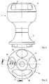
- Figure 2 shows an elevational view of an enlarged detail of the dishwashing machine as in Figure 1, according to a preferred embodiment;
- Figure 3 shows a top view of the detail as in Figure 2;
- Figure 4 shows a longitudinal cross-section of the detail, taken along lines IV-IV of Figure 3;
- Figure 5 shows a second embodiment of the detail as in Figure 4;
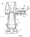
- Figure 6 shows a further embodiment of the detail as in Figure 4.
- With reference in particular to Figure 1, the dishwashing machine basically comprises a
wash tub 3 in which are housed at least alower basket 4 and at least an upper basket 5, respectively, for supporting crockery. Thebaskets 4 and 5 are in known manner removable from thewash tub 3 and are disposed aboverelevant spray arms 6 and 7, respectively, arranged to be fed with water by a circulating pump 9 through asupply tube 8. More particularly, thesupply tube 8 extends outside thewash tub 3 upwards and terminates with acentral nozzle 10 projecting into the wash tub through the top wall thereof. Theupper spray arm 7 is centrally provided with a substantially vertical water feeding conduit through which it is rotatably supported by the basket 5. As disclosed for instance in the above-mentioned GB-A-1 514 652 and shown in Figure 4, the water feeding conduit includes adiffuser 11 which is integral with thespray arm 7 and forms a rotary hydraulic joint with an adjacent convergenttubular portion 12. In particular, thediffuser 11 is freely rotatably mounted on the interior of ashaped support frame 2, that in turn is mounted on the basket 5 through snap-fitting fastening means 13 (see Figures 1 and 4). When the upper basket 5 is placed in position in thewash tub 3 thefeeding conduit nozzle 10, from which it is spaced by an air gap, to collect a supply water jet therefrom. - With reference also to Figures 2 and 3, according to the invention the feeding, or collecting
conduit dispenser 1 comprises ahollow body 14 having a goblet-shaped configuration, the lower portion of which is smaller in diameter and is mounted on the upper part of thesupport frame 2. More particularly, thebody 14 is fitted about theframe 2, in a detachable fashion, through bayonet fitting means 15 or similar snap-fitting fastening means. Thehollow body 14 is provided at the top with acover member 16 which is preferably formed in a single piece with the convergenttubular portion 12 of the collecting conduit and has at least anaperture 17 for loading the detergent. Preferably, thecover 16 is formed with indentations 24 (see Figure 3) which enable it to be suitably grasped, the cover being coupled with thebody 14 in a detachable way, for instance through snap-fitting fastening means 18 (see Figure 4), to the purpose of a possible cleaning of thewhole detergent dispenser 1. - The inner surface of the
hollow body 14 is provided with thin projections (or a corresponding annular rib) 19 which extend upwardly and upon which a substantially cup-shaped element 20 is arranged to rest coaxially. Thecup element 20 is formed with acentral hole 21 having a larger diameter than that of the coupling section between thetubular members air gap 26 between the twomembers outer clutch ring 22, the lower surface of which (smooth, in order to reduce friction) rests on theframe 2 for supporting purposes. The lower edge of thehole 21 of the cup-shaped element 20, in turn, rests on the upper surface of thering 22, upon which theelement 20 can be centred by means of aring nut 23, or the like. Theclutch ring 22, rotatably integral with thespray arm 7 and thediffuser 11, is capable of rotatably driving the cup-shaped element 20, and to this purpose its upper surface is preferably coupled with the lower edge of thehole 21 through friction means which are not shown for simplicity sake and for instance consist of relevant knurlings, or the like. - According to another aspect of the invention, the upper edge of the
hole 21 is formed with anannular projection 27 extending axially towards the interior of the cup-shaped element 20; the upper end portion of theprojection 27 is substantially surrounded by the edge of anannular wall 25 extending from thecover 16 downwardly. Hence, it is possible to load a suitable metered amount of detergent (preferably a powder detergent) into the cup-shaped element 20, through theloading aperture 17, without the risk of leakages of detergent through thehole 21. At the same time, theloading aperture 17 of thedetergent dispenser 1 keeps being hydraulically in communication with thespray arm 7 via the interior of the cup-shaped element 20; the gap which separates theprojection 27 of the cup-shaped element from theannular wall 25 and from theconvergent member 12; theair gap 26; and thediffuser 11. - In operation, therefore, the user can first load a metered amount of detergent into the cup-
shaped element 20 through theaperture 17; this operation is made easier thanks to the possibility of readily removing and replacing again thewhole dispenser 1, by virtue of the bayonet fitting means 15. Obviously, depending on the characteristics of the dishwashing machine and the operative programme which is selected, the detergent may be used to perform either a washing or a prewashing cycle; in the latter case, a metered amount of detergent to carry out a subsequent washing phase may be supplied to thewash tub 3, at a proper time, by means of a traditional separate detergent dispenser, not shown for the sake of simplicity. - When the selected operative programme is started, the circulating pump 9 supplies water to the
spray arms 6 and 7, which thereby issue a set of water jets impinging onto the crockery to be washed (not shown for simplicity sake) and rotate by hydraulic reaction. Therefore, the rotatingspray arm 7 and thediffuser 11 drive also the cup-shaped element 20 into rotation, into which element part of the water which is suspended in thewash tub 3 penetrates from above through theaperture 17. This combined - mechanical and hydraulic - action conveys the detergent, through the gap among theprojection 27 and themembers cover 16, and then through theair gap 26, along thediffuser 11 and to thespray arm 7. It should be noted that the detergent is also "drawn" into thediffuser 11 thanks to the negative pressure produced in correspondence of theair gap 26 by the water jet from thenozzle 10. As a result, the detergent is quickly and completely sprayed onto the crockery to be washed, along with the water jets issuing from thespray arm 7, the detergent being thereby able to exert its chemical action on the crockery, with no significant loss, right from the beginning of the operation of the machine. - The delivery of detergent from the
dispenser 1 is preferably promoted by the provision of at least one scraper wall 28 (three such walls are shown, in the embodiment herein described) extending from thecover 16 downwards inside the cup-shaped element 20. As shown in Figure 3, thescraper 28 is inclined towards thehole 21, with respect to the direction of rotation of the spray arm 7 (which rotates clockwise, in the present embodiment), so as to stir and convey the detergent to thehole 21 by virtue of the rotating movement of the cup-shaped element 20. As a result, thedetergent dispenser 1 is particularly effective and "self-cleaning" in operation. - If, however, clots of detergent are formed in the
dispenser 1, in particularly critical circumstances, which interfere with the rotation of the cup-shaped element 20, the frictional connection arrangement between theclutch ring 22 and theelement 20 "skids", thereby enabling at least thespray arm 7 to rotate correctly so as to minimize all consequences in the operation of the machine. - In the alternative embodiment shown in Figure 5, for example, the cup-
shaped element 20 is steady, integral with thecover 16, while only thespray arm 7 and thediffuser 11 are rotatable. In addition, thecentral hole 21 of the cup-shaped element has a slightly smaller diameter than that of the coupling section between thetubular members inner projection 27, which is preferably sharpened, forms an annular baffle which diverts part of the water flow from the convergenttubular member 12 and theair gap 26 towards the cup-shaped element 20. Hence, the detergent is flushed off thedispenser 1, through theloading aperture 17, toward the water jets, in particular those produced by thesubjacent spray arm 7, so as to be intercepted by the water jets and brought into contact with the crockery being washed. - In the embodiment shown in Figure 6, the cup-
shaped element 20 is arranged outside thedetergent dispenser 1. In particular, the cup-shaped element 20 is keyed on ashaft 29 which is rotatably mounted on aside projection 30 of thehollow body 14 to be driven into rotation by thediffuser 11 through gear means. These latters for instance comprise atoothing 31 provided on theshaft 29 and connected via at least agear wheel 32 with acorresponding toothing 33 provided on the outer surface of agear ring 34, which is similar to the clutch ring shown in Figure 4. Thetoothings gear wheel 32 are preferably housed within theside projection 30 of the detergent dispenser. In any case, when the circulating pump 9 is in operation thegear ring 34 rotates together with thediffuser 11 and thespray arm 7 and drives into rotation, with a suitable gear ratio, also the cup-shapedelement 20. - Therefore, the detergent previously loaded into the cup-shaped
element 20 is quickly and completely delivered by centrifugal action, as well as owing to the falling down of the water suspended in thewash tub 3, so as to be intercepted by the water jets of thesubjacent spray arms 6, 7.
Claims (8)
- Dishwashing machine comprising a wash tub in which are housed at least a detergent dispenser (1) and at least a removable basket disposed above a relevant rotary spray arm which is arranged to be supplied through a feeding conduit (11,12) with water circulated by a pump (9), so as to spray water jets towards the crockery supported by said basket, said detergent dispenser comprising a substantially cup-shaped element (20) capable of containing the detergent and being hydraulically associated with said feeding conduit (11,12) in order that the detergent contained therein is flushed by part of the water circulated by said pump (9) so that said detergent is delivered by the dispenser and sprayed onto the crockery along with said water jets, said feeding conduit (11,12) comprising an air gap (26) and a diffuser (11) which is rotatably integral with the spray arm (7) and arranged to drive said cup-shaped element (20) into rotation through clutch means (22; 29,31,32,33).
- Dishwashing machine according to claim 1, characterized in that said clutch means (22) are arranged to frictionally connect the cup-shaped element (20) with said diffuser (11).
- Dishwashing machine according to claim 1, characterized in that said cup-shaped element (20) includes a central hole (21) whose edge substantially surrounds said air gap (26) in correspondence of the diffuser (11), the cup-shaped element being arranged to receive from above part of the water sprayed by said spray arm (7), so as to deliver the detergent towards said water jets through said central hole (21), said air gap (26), said diffuser (11) and said spray arm (7).
- Dishwashing machine according to claim 3, characterized in that the edge of said central hole (21) is formed with an annular projection (27) extending within the cup-shaped element (20).
- Dishwashing machine according to claim 3, characterized in that said detergent dispenser (1) comprises a hollow body (14) which is mounted on said basket (5), houses said cup-shaped element (20) and is provided at the top with a cover member (16) having a convergent tubular member (12) that forms part of said feeding circuit and is coupled with the diffuser (11) through said air gap (26), said cover member being provided with at least an aperture (17), for loading the detergent, arranged to receive said part of the water sprayed by the spray arm (7).
- Dishwashing machine according to claim 5, characterized in that said cover member (16) comprises at least one scraper wall (28) extending within the cup-shaped element (20) and inclined towards said central hole (21) with respect to the direction of rotation of said spray arm (7).
- Dishwashing machine according to claim 1, characterized in that said cup-shaped element (20) comprises a central hole (21) substantially coaxial with the diffuser (11) and located in correspondence of said air gap (26), the edge of said central hole being formed with an annular projection (27) extending within the cup-shaped element and arranged to divert into the cup-shaped element (20) part of the water being circulated through said air gap (26), so as to flush the detergent into the wash tub (3), where it is intercepted by the water jets produced by the spray arm (7).
- Dishwashing machine according to claim 1, characterized in that said detergent dispenser (1) comprises a side projection (30) on the exterior of which said cup-shaped element (20) is rotatably mounted, so as to receive from above part of the water sprayed by said spray arm (7) and to deliver the detergent, by centrifugal action, into the wash tub (3), where it is intercepted by the water jets produced by the spray arm.
Applications Claiming Priority (2)
| Application Number | Priority Date | Filing Date | Title |
|---|---|---|---|
| ITPN910033A IT1250392B (en) | 1991-06-07 | 1991-06-07 | DISHWASHER WITH DETERGENT DISPENSER |
| ITPN910033 | 1991-06-07 |
Publications (2)
| Publication Number | Publication Date |
|---|---|
| EP0517015A1 EP0517015A1 (en) | 1992-12-09 |
| EP0517015B1 true EP0517015B1 (en) | 1995-05-03 |
Family
ID=11394538
Family Applications (1)
| Application Number | Title | Priority Date | Filing Date |
|---|---|---|---|
| EP92108189A Expired - Lifetime EP0517015B1 (en) | 1991-06-07 | 1992-05-15 | Dishwashing machine with detergent dispenser |
Country Status (5)
| Country | Link |
|---|---|
| US (1) | US5235994A (en) |
| EP (1) | EP0517015B1 (en) |
| DE (1) | DE69202303T2 (en) |
| ES (1) | ES2074762T3 (en) |
| IT (1) | IT1250392B (en) |
Families Citing this family (33)
| Publication number | Priority date | Publication date | Assignee | Title |
|---|---|---|---|---|
| US5546968A (en) * | 1993-10-23 | 1996-08-20 | Goldstar Co., Ltd. | Supplementary washing device of a dish washer |
| US5499640A (en) * | 1995-02-24 | 1996-03-19 | White Consolidated Industries, Inc. | Dishwasher with venturi drain |
| DE69527058T2 (en) | 1995-07-28 | 2002-10-31 | Whirlpool Corp., Benton Harbor | Dishwasher with detergent and brightener metering device arranged on a movable basket |
| US5752533A (en) * | 1996-06-11 | 1998-05-19 | White Consolidated Industries, Inc. | Jet spray nozzle with third level wash arm |
| US5727581A (en) * | 1996-10-02 | 1998-03-17 | General Electric Company | Dishwasher spray-arm assembly |
| IT243409Y1 (en) * | 1997-01-29 | 2002-03-04 | Electrolux Zanussi Elettrodome | DISHWASHER WITH DETERGENT DISPENSER |
| FR2761254B1 (en) * | 1997-03-28 | 1999-06-11 | Esswein Sa | DISPENSER DEVICE FOR DISHWASHER |
| DE19812329C1 (en) * | 1998-03-20 | 1999-06-10 | Whirlpool Co | Dishwasher machine with rotatable and removable spray arm |
| US7754025B1 (en) | 2000-06-08 | 2010-07-13 | Beverage Works, Inc. | Dishwasher having a door supply housing which holds dish washing supply for multiple wash cycles |
| US6799085B1 (en) | 2000-06-08 | 2004-09-28 | Beverage Works, Inc. | Appliance supply distribution, dispensing and use system method |
| US7083071B1 (en) | 2000-06-08 | 2006-08-01 | Beverage Works, Inc. | Drink supply canister for beverage dispensing apparatus |
| EP1479813A1 (en) * | 2003-05-21 | 2004-11-24 | AWECO APPLIANCE SYSTEMS GmbH & Co. KG | Household appliance with flushing device for dosing unit |
| US7523758B2 (en) | 2003-06-17 | 2009-04-28 | Whirlpool Corporation | Dishwasher having rotating zone wash sprayer |
| US7475696B2 (en) * | 2003-06-17 | 2009-01-13 | Whirlpool Corporation | Dishwasher having valved third-level sprayer |
| US7445013B2 (en) | 2003-06-17 | 2008-11-04 | Whirlpool Corporation | Multiple wash zone dishwasher |
| US8347898B2 (en) * | 2009-04-30 | 2013-01-08 | Whirlpool Corporation | Dishwasher with rotating zone wash sprayers |
| DE102010042579A1 (en) * | 2010-10-18 | 2012-04-19 | BSH Bosch und Siemens Hausgeräte GmbH | Dishwasher with at least one rotatable spray arm |
| US8734591B2 (en) | 2010-12-03 | 2014-05-27 | Whirlpool Corporation | Dishwasher with auxiliary, tough soil chemistry dispensing system |
| US9259138B2 (en) | 2010-12-07 | 2016-02-16 | Whirlpool Corporation | Dishwasher with auxiliary spray system having removable sprayers |
| US8931311B2 (en) * | 2011-04-26 | 2015-01-13 | General Electric Company | Additive dispenser for a washing machine |
| US8925561B2 (en) | 2011-10-11 | 2015-01-06 | Whirlpool Corporation | Dishwasher dispensing system with timed delay |
| US9119517B2 (en) | 2011-10-17 | 2015-09-01 | Whirlpool Corporation | Dishwasher having spray manifold and method for controlling same |
| US8721804B2 (en) | 2011-10-24 | 2014-05-13 | Whirlpool Corporation | Dishwasher with auxiliary washing agent dispensing system |
| US9034114B2 (en) | 2012-09-14 | 2015-05-19 | Whirlpool Corporation | Dishwasher with booster agent dispersal system |
| US9848754B2 (en) | 2012-11-19 | 2017-12-26 | Whirlpool Corporation | Dish rack with dispenser unit |
| EP2893862B1 (en) * | 2014-01-13 | 2017-11-29 | Miele & Cie. KG | Dishwasher |
| US10076224B2 (en) | 2014-01-20 | 2018-09-18 | Whirlpool Corporation | Dishwasher |
| CN111560729A (en) * | 2019-01-29 | 2020-08-21 | 青岛海尔智能技术研发有限公司 | Automatic feeding control method of washing machine and washing machine |
| US12312731B2 (en) | 2019-09-03 | 2025-05-27 | Whirlpool Corporation | Removable agitator with fabric softener dispenser |
| CN112442822B (en) | 2019-09-03 | 2023-08-15 | 惠而浦公司 | Laundry treatment appliance with removable garment exerciser |
| CN111449602B (en) * | 2020-03-24 | 2021-08-06 | 佛山市顺德区美的洗涤电器制造有限公司 | Spray lance, connecting piece, connector, spray lance assembly and belt cleaning device |
| CN111621961A (en) * | 2020-05-07 | 2020-09-04 | 杭州神林电子有限公司 | Anti-sucking device for detergent dispensing system |
| USD1051959S1 (en) | 2020-10-27 | 2024-11-19 | Whirlpool Corporation | Agitator |
Family Cites Families (16)
| Publication number | Priority date | Publication date | Assignee | Title |
|---|---|---|---|---|
| US1246556A (en) * | 1915-01-23 | 1917-11-13 | Jesse J Crow | Dish-washing machine. |
| US1997849A (en) * | 1929-08-17 | 1935-04-16 | Frederick C Bargar | Dishwashing apparatus |
| US2038260A (en) * | 1932-07-09 | 1936-04-21 | Edward C Chandler | Feeder device |
| US2062704A (en) * | 1934-02-20 | 1936-12-01 | Dorothy Edna Forsyth | Dishwashing machine |
| US2194342A (en) * | 1934-06-22 | 1940-03-19 | Edison General Elec Appliance | Dishwashing apparatus |
| US2127778A (en) * | 1935-11-12 | 1938-08-23 | Joseph D Lewis | Dishwashing and sterilizing machine |
| US2671037A (en) * | 1949-09-10 | 1954-03-02 | Gen Electric | Method of washing dishes or the like |
| CH386634A (en) * | 1960-07-12 | 1965-01-15 | Siemens Elektrogeraete Gmbh | dishwasher |
| FR1213629A (en) * | 1963-11-26 | 1960-04-01 | Thomson Houston Comp Francaise | Improvements to dishwashing machines |
| GB1100180A (en) * | 1965-10-23 | 1968-01-24 | Blackstone Corp | Domestic laundry machines |
| DE1628600A1 (en) * | 1966-10-01 | 1970-08-20 | Philips Nv | Dishwasher |
| US3444870A (en) * | 1966-12-12 | 1969-05-20 | Whirlpool Co | Article washing apparatus |
| US3699785A (en) * | 1971-03-10 | 1972-10-24 | Gen Electric | Additive dispensing arrangement |
| US3809106A (en) * | 1972-08-23 | 1974-05-07 | Fedders Corp | Dishwasher with improved spray apparatus |
| IT1050958B (en) * | 1975-09-24 | 1981-03-20 | Zanussi A Spa Industrie | IMPROVEMENTS IN DISHWASHER MACHINES |
| US4417457A (en) * | 1982-09-14 | 1983-11-29 | Whirlpool Corporation | Agitator mounted dispenser and shower spray device for automatic washer |
-
1991
- 1991-06-07 IT ITPN910033A patent/IT1250392B/en active IP Right Grant
-
1992
- 1992-05-15 ES ES92108189T patent/ES2074762T3/en not_active Expired - Lifetime
- 1992-05-15 EP EP92108189A patent/EP0517015B1/en not_active Expired - Lifetime
- 1992-05-15 DE DE69202303T patent/DE69202303T2/en not_active Expired - Fee Related
- 1992-05-20 US US07/886,508 patent/US5235994A/en not_active Expired - Fee Related
Also Published As
| Publication number | Publication date |
|---|---|
| ITPN910033A0 (en) | 1991-06-07 |
| ITPN910033A1 (en) | 1992-12-07 |
| DE69202303T2 (en) | 1996-01-25 |
| DE69202303D1 (en) | 1995-06-08 |
| ES2074762T3 (en) | 1995-09-16 |
| EP0517015A1 (en) | 1992-12-09 |
| US5235994A (en) | 1993-08-17 |
| IT1250392B (en) | 1995-04-07 |
Similar Documents
| Publication | Publication Date | Title |
|---|---|---|
| US5235994A (en) | Dishwashing machine with detergent dispenser | |
| US4186573A (en) | Rinse out centrifugally operated dispenser for automatic washer | |
| EP0726349B1 (en) | Method of washing for washing machine | |
| JP3300347B2 (en) | Dispenser for controlling the distribution of detergent in dishwashers | |
| CA1092840A (en) | Centrifugal dispenser for washing machine agitator | |
| US10231597B2 (en) | Household cleaning appliance with a single water flow path for both non-bulk and bulk dispensing | |
| KR100326889B1 (en) | Vertical axis washer | |
| US9976752B2 (en) | Detergent cartridge for cleaning device in ovens | |
| US4637230A (en) | Clothes washing machine | |
| US4509687A (en) | Multiple spray distribution system for a domestic dishwasher | |
| US3086379A (en) | Additive dispensing means for a cleaning machine | |
| US3736773A (en) | Additive dispenser for automatic washing machine | |
| US20140373284A1 (en) | Washing machine appliance dispensing cup with pump | |
| US3727434A (en) | Additive dispensing system | |
| US20020157190A1 (en) | Washing apparatus and method of washing laundry | |
| US5937677A (en) | Washing machine having a spraying nozzle assembly | |
| US3699785A (en) | Additive dispensing arrangement | |
| US5359744A (en) | Fabric softener dispenser system for an automatic washer | |
| US5823018A (en) | Washing machine having a spraying nozzle assembly | |
| US8875548B2 (en) | Laundry treating appliance with cleaning system for residual treating chemistry | |
| US20200008644A1 (en) | Dishwasher and method of controlling the same | |
| US3481163A (en) | Dispensing arrangement for washing machine | |
| US6092400A (en) | Washing machine | |
| EP0752493A1 (en) | Laundry washing machine having washing liquid filtering means | |
| US20220298710A1 (en) | Washing machine appliance with wash drum cleaning system |
Legal Events
| Date | Code | Title | Description |
|---|---|---|---|
| PUAI | Public reference made under article 153(3) epc to a published international application that has entered the european phase |
Free format text: ORIGINAL CODE: 0009012 |
|
| AK | Designated contracting states |
Kind code of ref document: A1 Designated state(s): DE ES FR GB IT |
|
| 17P | Request for examination filed |
Effective date: 19930112 |
|
| 17Q | First examination report despatched |
Effective date: 19940503 |
|
| ITF | It: translation for a ep patent filed | ||
| GRAA | (expected) grant |
Free format text: ORIGINAL CODE: 0009210 |
|
| AK | Designated contracting states |
Kind code of ref document: B1 Designated state(s): DE ES FR GB IT |
|
| REF | Corresponds to: |
Ref document number: 69202303 Country of ref document: DE Date of ref document: 19950608 |
|
| ET | Fr: translation filed | ||
| PLBE | No opposition filed within time limit |
Free format text: ORIGINAL CODE: 0009261 |
|
| STAA | Information on the status of an ep patent application or granted ep patent |
Free format text: STATUS: NO OPPOSITION FILED WITHIN TIME LIMIT |
|
| 26N | No opposition filed | ||
| REG | Reference to a national code |
Ref country code: ES Ref legal event code: PC2A Owner name: ELECTROLUX ZANUSSI ELETTRODOMESTICI, S.P.A. |
|
| REG | Reference to a national code |
Ref country code: ES Ref legal event code: PC2A |
|
| REG | Reference to a national code |
Ref country code: GB Ref legal event code: IF02 |
|
| PGFP | Annual fee paid to national office [announced via postgrant information from national office to epo] |
Ref country code: FR Payment date: 20030411 Year of fee payment: 12 |
|
| PGFP | Annual fee paid to national office [announced via postgrant information from national office to epo] |
Ref country code: GB Payment date: 20030417 Year of fee payment: 12 |
|
| PGFP | Annual fee paid to national office [announced via postgrant information from national office to epo] |
Ref country code: DE Payment date: 20030428 Year of fee payment: 12 |
|
| PGFP | Annual fee paid to national office [announced via postgrant information from national office to epo] |
Ref country code: ES Payment date: 20030506 Year of fee payment: 12 |
|
| PG25 | Lapsed in a contracting state [announced via postgrant information from national office to epo] |
Ref country code: GB Free format text: LAPSE BECAUSE OF NON-PAYMENT OF DUE FEES Effective date: 20040515 |
|
| PG25 | Lapsed in a contracting state [announced via postgrant information from national office to epo] |
Ref country code: ES Free format text: LAPSE BECAUSE OF NON-PAYMENT OF DUE FEES Effective date: 20040517 |
|
| PG25 | Lapsed in a contracting state [announced via postgrant information from national office to epo] |
Ref country code: DE Free format text: LAPSE BECAUSE OF NON-PAYMENT OF DUE FEES Effective date: 20041201 |
|
| GBPC | Gb: european patent ceased through non-payment of renewal fee |
Effective date: 20040515 |
|
| PG25 | Lapsed in a contracting state [announced via postgrant information from national office to epo] |
Ref country code: FR Free format text: LAPSE BECAUSE OF NON-PAYMENT OF DUE FEES Effective date: 20050131 |
|
| REG | Reference to a national code |
Ref country code: FR Ref legal event code: ST |
|
| PG25 | Lapsed in a contracting state [announced via postgrant information from national office to epo] |
Ref country code: IT Free format text: LAPSE BECAUSE OF NON-PAYMENT OF DUE FEES;WARNING: LAPSES OF ITALIAN PATENTS WITH EFFECTIVE DATE BEFORE 2007 MAY HAVE OCCURRED AT ANY TIME BEFORE 2007. THE CORRECT EFFECTIVE DATE MAY BE DIFFERENT FROM THE ONE RECORDED. Effective date: 20050515 |
|
| REG | Reference to a national code |
Ref country code: ES Ref legal event code: FD2A Effective date: 20040517 |