EP0516247A1 - Thermal transfer type printer - Google Patents
Thermal transfer type printer Download PDFInfo
- Publication number
- EP0516247A1 EP0516247A1 EP92202307A EP92202307A EP0516247A1 EP 0516247 A1 EP0516247 A1 EP 0516247A1 EP 92202307 A EP92202307 A EP 92202307A EP 92202307 A EP92202307 A EP 92202307A EP 0516247 A1 EP0516247 A1 EP 0516247A1
- Authority
- EP
- European Patent Office
- Prior art keywords
- current
- data
- time
- thermal head
- temperature
- Prior art date
- Legal status (The legal status is an assumption and is not a legal conclusion. Google has not performed a legal analysis and makes no representation as to the accuracy of the status listed.)
- Granted
Links
Images

Classifications
-
- B—PERFORMING OPERATIONS; TRANSPORTING
- B41—PRINTING; LINING MACHINES; TYPEWRITERS; STAMPS
- B41J—TYPEWRITERS; SELECTIVE PRINTING MECHANISMS, i.e. MECHANISMS PRINTING OTHERWISE THAN FROM A FORME; CORRECTION OF TYPOGRAPHICAL ERRORS
- B41J2/00—Typewriters or selective printing mechanisms characterised by the printing or marking process for which they are designed
- B41J2/315—Typewriters or selective printing mechanisms characterised by the printing or marking process for which they are designed characterised by selective application of heat to a heat sensitive printing or impression-transfer material
- B41J2/32—Typewriters or selective printing mechanisms characterised by the printing or marking process for which they are designed characterised by selective application of heat to a heat sensitive printing or impression-transfer material using thermal heads
- B41J2/35—Typewriters or selective printing mechanisms characterised by the printing or marking process for which they are designed characterised by selective application of heat to a heat sensitive printing or impression-transfer material using thermal heads providing current or voltage to the thermal head
- B41J2/355—Control circuits for heating-element selection
- B41J2/36—Print density control
- B41J2/365—Print density control by compensation for variation in temperature
-
- B—PERFORMING OPERATIONS; TRANSPORTING
- B41—PRINTING; LINING MACHINES; TYPEWRITERS; STAMPS
- B41J—TYPEWRITERS; SELECTIVE PRINTING MECHANISMS, i.e. MECHANISMS PRINTING OTHERWISE THAN FROM A FORME; CORRECTION OF TYPOGRAPHICAL ERRORS
- B41J2/00—Typewriters or selective printing mechanisms characterised by the printing or marking process for which they are designed
- B41J2/315—Typewriters or selective printing mechanisms characterised by the printing or marking process for which they are designed characterised by selective application of heat to a heat sensitive printing or impression-transfer material
- B41J2/32—Typewriters or selective printing mechanisms characterised by the printing or marking process for which they are designed characterised by selective application of heat to a heat sensitive printing or impression-transfer material using thermal heads
- B41J2/325—Typewriters or selective printing mechanisms characterised by the printing or marking process for which they are designed characterised by selective application of heat to a heat sensitive printing or impression-transfer material using thermal heads by selective transfer of ink from ink carrier, e.g. from ink ribbon or sheet
-
- B—PERFORMING OPERATIONS; TRANSPORTING
- B41—PRINTING; LINING MACHINES; TYPEWRITERS; STAMPS
- B41J—TYPEWRITERS; SELECTIVE PRINTING MECHANISMS, i.e. MECHANISMS PRINTING OTHERWISE THAN FROM A FORME; CORRECTION OF TYPOGRAPHICAL ERRORS
- B41J2/00—Typewriters or selective printing mechanisms characterised by the printing or marking process for which they are designed
- B41J2/315—Typewriters or selective printing mechanisms characterised by the printing or marking process for which they are designed characterised by selective application of heat to a heat sensitive printing or impression-transfer material
- B41J2/32—Typewriters or selective printing mechanisms characterised by the printing or marking process for which they are designed characterised by selective application of heat to a heat sensitive printing or impression-transfer material using thermal heads
- B41J2/35—Typewriters or selective printing mechanisms characterised by the printing or marking process for which they are designed characterised by selective application of heat to a heat sensitive printing or impression-transfer material using thermal heads providing current or voltage to the thermal head
- B41J2/355—Control circuits for heating-element selection
- B41J2/36—Print density control
Definitions
- the present invention generally relates to thermal transfer type printers, and more particularly to a thermal transfer type printer capable of varying a printing density thereof based on printing data which select desirable printing density.
- a thermal transfer type printer prints bar codes, characters and graphics on a printing paper by use of a transfer ribbon and a line thermal head (hereinafter, referred to as a thermal head). More specifically, thermal melting ink is painted on a surface of the transfer ribbon so that an ink layer is formed on the surface of the transfer ribbon, and this ink layer of the transfer ribbon is pressed against the printing paper. The thermal head is pressed against the backside of the transfer ribbon and heated so as to melt the thermal melting ink of the ink layer in response to a desirable pattern. Such melted ink is transferred on the printing paper. Thus, the desirable pattern is printed on the printing paper.
- a thermosensitive type printer is also well known. In such thermosensitive type printer, a printing pattern is directly given to a thermosensitive paper so that the printing pattern is printed on the thermosensitive paper.
- the printing density is generally set to a predetermined fixed density by use of a volume and a switch.
- a density control circuit is provided for maintaining a high printing quality. More specifically, the density control circuit controls a heating temperature of the thermal head based on the present temperature of the thermal head detected by a thermistor so that the printing density is maintained at the predetermined fixed density.
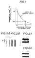
- this density control circuit provides a memory (e.g., ROM) therein, which is written by data concerning a current-on time (i.e., a period for supplying the current to the thermal head). As shown in Fig.
- this current-on times are estimated from current-on characteristics (shown as a curve for supplied energy) which determine a value of a current supplied to the thermal head.
- the respective data of the current-on times obtained from the above curve (shown in Fig. 1) will be shown in the following Table 1.
- a period for supplying the current to the thermal head is determined. For example, in the case where a printing operation must be stopped immediately after a power switch of a printer is turned on, the current-on time is set relatively longer because an initial temperature of the thermal head is relatively low. When the initial temperature of the thermal head is set at 0 degree centigrade, it is apparent from Fig. 1 that the desirable current-on time is 3 ms (i.e., 3 millisecond). On the contrary, when the temperature of the thermal head rises to a sufficiently high temperature, the current-on time can be shorter. For example, when the temperature of the thermal head is at 60 degrees centigrade, the desirable current-on time is 0.5 ms. As described above, the density control circuit detects the temperature of the thermal head by the thermistor (which is provided within the thermal head) and determines the desirable current-on time where the printing density is controlled to become constant.
- the thermistor which is provided within the thermal head
- the conventional thermal transfer type printers include a bar code printer and a color printer and the like.
- bar code printer is used in several fields, such as a factory automation (FA) field, a distribution industry field and the like.
- FA factory automation
- OA office automation
- CAD computer aided design
- the printing density is maintained constant in the conventional thermal transfer type printer, regardless of kinds of the printing density.
- the conventional printer suffers a problem in that it is impossible for an external control device (such as a computer etc.) to vary the printing density in accordance with character patterns.
- a variable density switch enables the printer to vary the printing density of all printed patterns. Even in the printer having such a variable density switch, however, it is impossible to vary the printing density by every character data.
- the horizontal bar codes differ from the vertical bar codes by a reading direction of the bar code reader. More specifically, data of the horizontal bar codes can be read by the bar code reader in a horizontal direction, and data of the vertical bar codes can be read by the bar code reader in a vertical direction.
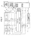
- Figs. 2A, 2B, 3A and 3B show printed dots of the thermal transfer type bar code printer. More specifically, Figs. 2A and 2B show horizontal bar codes which are read by the bar code reader in the horizontal direction indicated by an arrow H, and Figs. 3A and 3B show vertical bar codes which are read by the bar code reader in the vertical direction indicated by an arrow V.
- Fig. 2A designates the horizontal bar codes in the case where the current-on time of the thermal head is set relatively short. As shown in Fig. 2A, the printing density is therefore faint and a distance A is formed between two adjacent dots. This horizontal bar code must be formed in a continuous line, however, the horizontal bar code is actually formed in a dotted line. On the contrary, in the case where the current-on time of the thermal head is set relatively long as shown in Fig. 2B in order to prevent the above phenomenon, sizes of dots become large and the two adjacent dots are connected together so that the horizontal bar code is formed in the continuous line.
- Fig. 3A designates vertical bar codes in the case where the current-on time of the thermal head is set relatively long. As shown in Fig. 3A, the printing density of the vertical bar codes becomes deep so that two adjacent vertical bar codes are connected by overflow ink. This phenomenon is called "tailing" phenomenon. In order to prevent such tailing phenomenon from occurring, the current-on time of the thermal head must be set short so as to make the sizes of dots small as shown in Figure 3B.
- a thermal transfer type printer comprising: (a) memory means for storing print data corresponding to the desirable dot pattern and first and second current-on time data, each of the first and second current-on time data representing data of specific current-on time characteristics designating a relation between the current-on time and the surrounding temperature of the thermal head, the value of the first current-on time data being set higher than the value of the second current-on time data; (b) temperature detecting means for detecting the surrounding temperature of the thermal head and outputting temperature data corresponding to detected surrounding temperature of the thermal head; and (c) thermal head control means for controlling the temperature of the thermal head by varying the current-on times of the heating cells based on the print data and a control signal, the print data selecting heating cells to be heated, the control signal selecting one of the first and second current-on time data stored in the memory means so that an optimum current-on time is read from the current-on time characteristics corresponding to selected current-on time
- a thermal transfer type printer comprising: (a) first memory means for storing character data corresponding to the desirable dot pattern and reference current-on time data representing data of reference current-on time characteristics designating a relation between the current-on time and the surrounding temperature of the thermal head; (b) second memory means for storing density data including density command and increment/decrement value which is arbitrarily set, the reference current-on time data being designated by the density command; (c) temperature detecting means for detecting the surrounding temperature of the thermal head and outputting temperature data corresponding to detected surrounding temperature of the thermal head; and (d) thermal head control means for controlling the temperature of the thermal head by varying the current-on times of the heating cells based on the density data and the temperature data, the character data selecting heating cells to be heated, the reference current-on time being read from the reference current-on time characteristics based on the temperature data and the reference current-on time being increased or decreased based on the increment/decrement value so as to calculate out an optimum current-on
- Fig. 4 is a mechanical diagram showing an embodiment of a constitution of a thermal transfer type bar code printer according to the present invention.
- 1 designates a transfer ribbon, the upper surface of which is painted with thermal melting ink.
- This transfer ribbon 1 is transmitted from a supply reel 2 and is passed through a printing portion 3, and thereafter, the transfer ribbon 1 is taken up by a take-up reel 4.
- 5 designates a printing paper, one surface of which is pressed against and touched together with the upper surface of the transfer ribbon 1.
- This printing paper 5 piled with the transfer ribbon 1 is passed through the printing portion 3.
- the printing portion 3 consists of a thermal head 6 and a platen roller 7.
- the thermal head 6 provides heating cells (which will be described later) which are heated by supplying currents thereto.
- the thermal head 6 When the printing operation is performed, the thermal head 6 is forced to be pressed against the platen roller 7, so that the transfer ribbon 1 and the printing paper 5 are piled together under the pressure applied between the thermal head 6 and the platen roller 7. In this case, the heated heating cells melt the ink painted on the transfer ribbon 1 and the melted ink is transferred to the printing paper 5. Furthermore, the platen roller 7 revolves by a minute distance in a direction Y, so that the transfer ribbon 1 and the printing paper 5 can advance by every dots. The heating temperature of the thermal head 6 can be measured by a thermistor 8 mounted on the thermal head 6.
- Fig. 5 is a block diagram showing an electric connection of the printer shown in Fig. 4.
- 10 designates a temperature detecting circuit which is constituted by an analog-to-digital (A/D) converter 9 and the thermistor 8.
- the analog output signal of the thermistor 8 is converted into digital data in the A/D converter 9.
- This digital data are supplied to a control portion 11 as temperature data, the value of which represents the temperature of the thermal head 6.
- An interface circuit 12 is inserted to transfer several kinds of data between an external computer (not shown) and the control portion 11.
- Such data include print data DA, a control signal ESCH for printing the horizontal bar codes and a control signal ESCV for printing the vertical bar codes.
- control portion 11 consists of a central processing unit (CPU), a work memory and a program memory (not shown) and the like.
- This control portion 11 controls several portions within the printer and supplies current-on time data TD to a current-on control circuit 17 in order to determine the current-on time for the thermal head 6.
- Such current-on time data TD are stored as a table in a current-on time data memory 15 (hereinafter, referred simply as to a memory 15).
- a memory 15 hereinafter, referred simply as to a memory 15.
- the control portion 11 reads optimum current-on time data TD from the memory 15 in accordance with several kinds of required conditions.
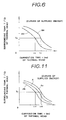
- Fig. 6 shows curves of supplied energy, the data of which are stored in the memory 15.
- a x-axis represents the current-on time
- a y-axis represents a surrounding temperature of the thermal head 6.
- Two curves AV and BH are shown in Fig. 6, and the supplied energy on the curve BH is higher than that of the curve AV.
- the data of these two curves are stored in the memory 15 as numeric value table etc.
- the curve BH represents the optimum printing density for printing the horizontal bar codes, and the data of such printing density are pre-obtained in an experiment on the current-on time characteristics of the thermal head.
- the curve AV represents the optimum printing density for printing the vertical bar codes.
- the control portion 11 selects the data of the curve AV when the signal ESCV is supplied thereto.
- the control portion 11 selects the data of the curve BH when the signal ESCH is supplied thereto.
- a current-on time t1 is read from the curve AV
- a current-on time t2 is read from the curve BH.
- the control portion 11 determines the current-on time data TD based on the temperature data from the temperature detecting circuit 10 and selected one of the curves AV and BH.
- the data stored in the memory 15 are read out based on address data ADR which are renewed by every data read-out timings in the control portion 11. For example, the upper data within the address data ADR are determined by one of the signals ESCH and ESCV, and the lower data within the address data ADR are determined by the temperature data from the temperature detecting circuit 10.
- 13 designates a motor drive circuit which drives a step motor 14 so as to revolve the platen roller 7 by a predetermined step distance under the control of the control portion 11.
- 16 designates a print data memory which stores dot data (which represent dot patterns of the bar codes) supplied from the external computer (not shown) and the like. The dot data are read out from the print data memory 16 based on the address data ADR supplied from the control portion 11 and such dot data are supplied to a head drive circuit 18.
- the current-on control circuit 17 supplies the currents to the selected heating cells for a period corresponding to the current-on time data TD. As shown in Fig.
- this current-on time control circuit 17 consists of a programmable timer 17a and AND gates AN1 to AN n .
- the current-on time data TD are preset in the programmable timer 17a by the control portion 11.
- the one input terminals of the AND gates AN1 to AN n are connected in common to the output terminal of the programmable timer 17a, and common signals C1 to C n outputted from the control portion 11 are supplied respectively to other input terminals of the AND gates AN1 to AN n .
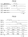
- These common signals C1 to C n have the same constant pulse width, and the leading edge timings of such common signals C1 to C n are sequentially shifted by a predetermined time as shown in Figs. 8(d) and 8(e).
- the head drive circuit 18 supplies the currents to heating cells TH1 to THn within the thermal head 6 in correspondence with the dot data supplied from the print data memory 16.
- This head drive circuit 18 consists of a shift register SR, a latch circuit LC and drive gates G1 to G n corresponding to the heating cells TH1 to TH n .
- the dot data DA i.e., the print data DA
- a latch signal DR shown in Fig.
- the head drive circuit 18 supplies currents so as to heat the heating cells TH1 to TH n based on the dot data DA and pulse signals outputted from the AND gates AN1 to AN n within the current-on control circuit 17. As shown in Fig. 8, the operation of the head drive circuit 18 and the timings of the common signals C1 to C n are determined such that the common signal C1 is outputted when the dot data DA is latched in the latch circuit LC. Thereafter, the common signals C2 to C n are sequentially outputted at every data latch timings.
- the control portion 11 writes the dot data DA into the print data memory 16 and selects the curve BH, the data of which are stored in the current-on time data memory 15.
- the head drive circuit 18 writes the dot data DA into the shift register SR and the latch circuit LC sequentially.
- the levels of the output signals of the latch circuit LC are set to the "1" level or the "0" level in response to the dot data DA.
- the latch circuit LC supplies the output signals thereof to the input terminals of the gates G1 to G n .
- the current-on time data TD and the common signals C1 to C n are determined based on the curve BH and the temperature data from the A/D converter 9 in the control portion 11. These current-on time data TD and the common signals C1 to C n are supplied to the current-on control circuit 17.
- logical product operations between an output signal P0 of the programmable timer 17a and the common signals C1 to C n are performed in the AND gates AN1 to AN n within the current-on control circuit 17.
- the AND gates AN1 to AN n output logical product signals to other input terminals of the gates G1 to G n .
- the "0" signal is outputted from the gates supplied with the logical product signals and the output signals of the latch circuit LC, both of which have the "1" level, and the currents are supplied to the corresponding heating cells within the heating cells TH1 and TH n .
- the curve BH is selected, whereby a "1" level period (i.e., a high level period) of the pulse signal P0 from the programmable timer 17a is set relatively long.
- the horizontal bar codes can be printed in the desirable printing density.
- the printing operation thereof is similar to that described heretofore except that the curve AV is selected. Due to the curve AV, the "1" level period of the pulse P0 is set relatively short. Thus, the vertical bar codes can be printed in the desirable printing density.
- Fig. 9 shows waveforms at several portions of the circuit shown in Fig. 7. More specifically, Figs. 9(e) and 9(f) represent the case where the curve BH is selected, and Figs. 9(g) and 9(h) represent the case where the curve AV is selected. Further, Figs. 9(f) and 9(h) indicate the heating cells to be supplied with the current and to be heated.
- the horizontal and vertical bar codes As described heretofore, it is possible to print the horizontal and vertical bar codes together with a constant printing density. Such horizontal and vertical bar codes can be printed together on bar code labels which are used for discriminating products in factories.
- the mechanism or the electric constitution of the bar code reader which can read both of the horizontal and vertical bar codes is more simple than that of the conventional bar code reader which can read only one of the horizontal and vertical bar codes, because the conventional bar code reader can not read the bar code, the reading direction of which is not identical to the predetermined reading direction.
- the constitution of the bar code reader according to the present invention is more simple than that of the conventional bar code reader.
- the mechanism of the conventional bar code reader must be rotated by 90 degrees in order to read such bar code, or the read data in the x-direction must be exchanged by the read data in the y-direction in the electric circuit of the bar code reader.
- the constitution of the conventional bar code reader must be complicated.
- the external computer supplies the control signal ESCH for printing the horizontal bar codes and the control signal ESCV for printing the vertical bar codes independently to the control portion 11 via the interface circuit 12.
- the dot data DA are constituted by eight bits, and the original dot data DA are assigned to seven bits within the combined data of eight bits.
- the original control signals ESCH and ESCV are assigned to remained one bit (hereinafter, referred to as a control bit) within the combined data.
- the horizontal bar codes are printed when the value of the control bit is equal to "0”
- the vertical bar codes are printed when the value of the control bit is equal to "1".
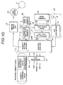
- Fig. 10 shows an electric constitution of the modified embodiment.
- the parts corresponding to those in Fig. 5 will be designated by the same numerals, and the description thereof will be omitted.
- the external computer supplies the print data DA and a standby signal STB to the control portion 11 via the interface circuit 12.
- the print data DA include character data DB and printing density data therein.
- the printing density data consist of a density command ESCDP and an increment/decrement value.
- This density command ESCDP represents reference density characteristics (i.e., reference current-on time characteristics) which correspond to a curve A shown in Fig. 11, and the value of the current-on time data is increased or decreased based on said increment/decrement value.
- This increment/decrement value is represented by data of eight bits. The 7-bit to 1-bit within such data of eight bits represent a value of printing density which indicates a desirable density percentage in a range between 0% to 100%.
- the 8-bit within such data represents a sign code. More specifically, the sign of such data is turned to a positive sign (+) when the 8-bit value is equal to "0", and the sign of such data is turned to a negative sign (-) when the 8-bit value is equal to "1".
- Fig. 11 shows curves A, Av and Ah of the supplied energy, the data of which are stored in the memory 15.
- This curve A represents a standard printing density which is pre-obtained in an experiment on the current-on time characteristics of the thermal head.
- the control portion 11 performs a calculation based on the increment/decrement value of the printing density data. Due to this calculation, the curve A can shift up or down in the y-axis direction in Fig. 11. More specifically, the curve A shifts down to the curve Ah when increment/decrement value of the printing density data represents a negative value, and the curve A shifts up to the curve Av when the increment/decrement value represents a positive value.
- a current-on time t11 can be read from the curve Ah and a current-on time t12 can be read from the curve Av when the surrounding temperature of the thermal head is equal to a temperature Ts.
- the control portion 11 determines the value of the current-on time data TD based on the data read from the curve A and the temperature data supplied from the temperature detecting circuit 10. In this case, the current-on time data are read out from the memory 15 based on the address data ADR, the value of which are renewed by every predetermined timings. The address indicated by the address data ADR is determined by the temperature data.
- the current-on time 2 ms can be read from the curve A.
- the actual current-on time data TD can be obtained from the following formula.
- (Current-on Time Data) TD (Reference Current-on Time) x [100 + ( ⁇ N)]/100
- N denotes as the increment/decrement value.
- the actual current-on time data TD corresponding to the read current-on time of 2 ms can be calculated as shown in the following formula.
- the control portion 11 can calculate out other current-on time data TD by use of the curve A based on the surrounding temperature of the thermal head and the increment/decrement value within the printing density data.
- the print data memory 16 stores the character data DB included within the print data DA which are supplied from the external computer.
- the head drive circuit 18 supplies the power to the heating cells selected in accordance with the character data DB which are supplied from the print data memory 16.
- the character data DB (shown in Fig. 8(a)) are supplied to and stored in the shift register SR based on the clock CLK (shown in Fig. 8(b)). Thereafter, the character data DB are stored in the latch circuit LC at a timing due to the latch signal DR (shown in Fig. 8(c)) which is outputted from the control portion 11 when the storing operation of the data DB is ended in the shift register SR.
- the head drive circuit 18 supplies the power to and heats the heating cells which are selected from the heating cells TH1 to TH n based on the character data DB and the pulse signals outputted from the AND gates AN1 to AN n within the current-on control circuit 17.
- the printing density data (the density command of which is set to -20%, for example) within the print data DA are passed through the interface circuit 12 and supplied to the control portion 11 wherein such printing density data are written into a density setting memory 11a.
- the character data DB within the print data DA are written into the print data memory 16. This character data DB are subject to a predetermined density control.
- the current-on time data TD are calculated out by the data read from the curve A based on a value of the printing density data stored within the density setting memory 11a and a value of the temperature data (e.g., a digital value indicating a temperature of 25 degrees centigrade) outputted from the temperature detecting circuit 10.
- the calculated value of the current-on time data TD is equal to 1.6 ms, for example.
- the character data DB within the print data DA are written into the shift register SR and then shifted to the latch circuit LC sequentially, whereby the latch circuit LC supplies signals (each of which has the "0" or "1" level) corresponding to the print data DA to the input terminals of the gates G1 to G n .
- control portion 11 supplies the calculated current-on time data TD and common signals C1 to C n to the current-on control circuit 17, wherein the AND gates AN1 to AN n perform the logical product operations between the output signal P0 from the timer 17a and the common signals C1 to C n .
- the AND gates AN1 to AN n output respective logical product signals to the other input terminals of the gates G1 to G n .
- the "0" signals are supplied to corresponding heating cells from the gates each of which is supplied with the "1" signal and the logical product signal having the "1" level, whereby the corresponding heating cells are given with the power and then heated.
- the "1" level period of the output signal P0 of the timer 17a is equal to 1.6 ms, which is shorter than the current-on time of the standard printing density. Hence, the sizes of the transferred dots become small and the printing density thereby becomes faint.
- the increment/decrement value of the density data is identified as a positive value
- the "1" level period of the output signal P0 of the timer 17a is set longer than the standard current-on time. Hence, the sizes of the transferred dots become relatively large and the printing density thereby becomes deep.
- thermal transfer type printer description has been given with respect to the thermal transfer type printer, however, it is apparent from the above-mentioned description that the present invention can be applied to the thermal transfer type color printer. Furthermore, the present invention can be applied to other thermal transfer type printer such as a thermal transfer type bar code printer.
- the quantity of the power supplied to the thermal head is lowered (e.g., the period for supplying print currents to the thermal head is shorten) when the printer is supplied with the negative density data, the negative value of which is set by the density command outputted from the external device.
- the quantity of the power supplied to the thermal head is increased when the printer is supplied with the positive density data. Therefore, the conventional printer suffers the tailing phenomenon which appears between two adjacent dots and which is caused by an overheating of the thermal head when the vertical bar codes are printed.
- the present invention can prevent such tailing phenomenon from being caused.
- the conventional printer suffers the clearance gap which is formed between two adjacent dots due to the shortage of heating power of the thermal head. According to the present invention, it is possible to vary the size of the transferred dot because the present invention can vary the printing density based on the data. In other words, the present invention can perform a gradient control for the printing density.
- the present invention can control the printing density and perform a gradient printing operation such that the sizes of the transferred dots are made small or large by varying the value of the density data.
- the present invention can easily perform a multi-color printing and also print intermediate colors other than the primary colors by use of a transfer color ribbon painted with a yellow color (Y), a magenta color (M) and a cyan color (C).
Landscapes
- Electronic Switches (AREA)
Abstract
Description
- The present invention generally relates to thermal transfer type printers, and more particularly to a thermal transfer type printer capable of varying a printing density thereof based on printing data which select desirable printing density.
- Conventionally, a thermal transfer type printer prints bar codes, characters and graphics on a printing paper by use of a transfer ribbon and a line thermal head (hereinafter, referred to as a thermal head). More specifically, thermal melting ink is painted on a surface of the transfer ribbon so that an ink layer is formed on the surface of the transfer ribbon, and this ink layer of the transfer ribbon is pressed against the printing paper. The thermal head is pressed against the backside of the transfer ribbon and heated so as to melt the thermal melting ink of the ink layer in response to a desirable pattern. Such melted ink is transferred on the printing paper. Thus, the desirable pattern is printed on the printing paper. Other than this thermal transfer type printer, a thermosensitive type printer is also well known. In such thermosensitive type printer, a printing pattern is directly given to a thermosensitive paper so that the printing pattern is printed on the thermosensitive paper.
- In the above-mentioned printers, the printing density is generally set to a predetermined fixed density by use of a volume and a switch. In some thermal transfer type printers, a density control circuit is provided for maintaining a high printing quality. More specifically, the density control circuit controls a heating temperature of the thermal head based on the present temperature of the thermal head detected by a thermistor so that the printing density is maintained at the predetermined fixed density. In addition, this density control circuit provides a memory (e.g., ROM) therein, which is written by data concerning a current-on time (i.e., a period for supplying the current to the thermal head). As shown in Fig. 1, this current-on times are estimated from current-on characteristics (shown as a curve for supplied energy) which determine a value of a current supplied to the thermal head. The respective data of the current-on times obtained from the above curve (shown in Fig. 1) will be shown in the following Table 1.

- Based on such data of current-on times, a period for supplying the current to the thermal head is determined. For example, in the case where a printing operation must be stopped immediately after a power switch of a printer is turned on, the current-on time is set relatively longer because an initial temperature of the thermal head is relatively low. When the initial temperature of the thermal head is set at 0 degree centigrade, it is apparent from Fig. 1 that the desirable current-on time is 3 ms (i.e., 3 millisecond). On the contrary, when the temperature of the thermal head rises to a sufficiently high temperature, the current-on time can be shorter. For example, when the temperature of the thermal head is at 60 degrees centigrade, the desirable current-on time is 0.5 ms. As described above, the density control circuit detects the temperature of the thermal head by the thermistor (which is provided within the thermal head) and determines the desirable current-on time where the printing density is controlled to become constant.
- Meanwhile, the conventional thermal transfer type printers include a bar code printer and a color printer and the like. Recently such bar code printer is used in several fields, such as a factory automation (FA) field, a distribution industry field and the like. In addition, such color printer is used in an office automation (OA) field and a computer aided design (CAD) field and the like. Due to demands of the above-mentioned fields, a highly fine-grained printing and a high printing quality are required for the printer.
- However, the printing density is maintained constant in the conventional thermal transfer type printer, regardless of kinds of the printing density. Hence, the conventional printer suffers a problem in that it is impossible for an external control device (such as a computer etc.) to vary the printing density in accordance with character patterns. A variable density switch enables the printer to vary the printing density of all printed patterns. Even in the printer having such a variable density switch, however, it is impossible to vary the printing density by every character data.
- Next, description will be given with respect to a variable density control of the thermal transfer type bar code printer, for example. When a density control condition is adjusted so that vertical bar codes are printed in a desirable printing density, the printing density of horizontal bar codes becomes faint and a clearance gap is formed between adjacent dots. On the contrary, when the density control condition is adjusted so that the horizontal bar codes are printed in a desirable printing density, the printing density of the vertical bar codes becomes too deep and the ink printed on one vertical bar code flows over to the adjacent vertical bar code so that the two adjacent vertical bar codes are connected together by such ink flow. This causes an error in reading data from the bar codes by a bar code reader.
- Incidentally, the horizontal bar codes differ from the vertical bar codes by a reading direction of the bar code reader. More specifically, data of the horizontal bar codes can be read by the bar code reader in a horizontal direction, and data of the vertical bar codes can be read by the bar code reader in a vertical direction.
- Figs. 2A, 2B, 3A and 3B show printed dots of the thermal transfer type bar code printer. More specifically, Figs. 2A and 2B show horizontal bar codes which are read by the bar code reader in the horizontal direction indicated by an arrow H, and Figs. 3A and 3B show vertical bar codes which are read by the bar code reader in the vertical direction indicated by an arrow V.
- Further, more specifically, Fig. 2A designates the horizontal bar codes in the case where the current-on time of the thermal head is set relatively short. As shown in Fig. 2A, the printing density is therefore faint and a distance A is formed between two adjacent dots. This horizontal bar code must be formed in a continuous line, however, the horizontal bar code is actually formed in a dotted line. On the contrary, in the case where the current-on time of the thermal head is set relatively long as shown in Fig. 2B in order to prevent the above phenomenon, sizes of dots become large and the two adjacent dots are connected together so that the horizontal bar code is formed in the continuous line.
- On the other hand, Fig. 3A designates vertical bar codes in the case where the current-on time of the thermal head is set relatively long. As shown in Fig. 3A, the printing density of the vertical bar codes becomes deep so that two adjacent vertical bar codes are connected by overflow ink. This phenomenon is called "tailing" phenomenon. In order to prevent such tailing phenomenon from occurring, the current-on time of the thermal head must be set short so as to make the sizes of dots small as shown in Figure 3B.
- As described heretofore, it is difficult to print the horizontal and vertical bar codes together on the printing paper and it is also difficult to control the printing densities of both bar codes at a constant printing density in the conventional thermal transfer type printer. Such difficulty of the conventional thermal transfer type printer also occurs in the conventional thermal transfer type color printer, in which the printing density cannot be varied in response to the contents of the print data.
- It is the primary object of the invention to provide a thermal transfer type printer in which a constantly high printing quality can be obtained even when the horizontal and vertical bar codes are printed together on the printing paper.
- It is another object of the invention to provide a thermal transfer type printer providing means for arbitrarily setting the printing density from an external device in response to the contents of the print data.
- The present invention is defined in the appended claims and according to a first aspect of the invention, there is provided a thermal transfer type printer comprising: (a) memory means for storing print data corresponding to the desirable dot pattern and first and second current-on time data, each of the first and second current-on time data representing data of specific current-on time characteristics designating a relation between the current-on time and the surrounding temperature of the thermal head, the value of the first current-on time data being set higher than the value of the second current-on time data; (b) temperature detecting means for detecting the surrounding temperature of the thermal head and outputting temperature data corresponding to detected surrounding temperature of the thermal head; and (c) thermal head control means for controlling the temperature of the thermal head by varying the current-on times of the heating cells based on the print data and a control signal, the print data selecting heating cells to be heated, the control signal selecting one of the first and second current-on time data stored in the memory means so that an optimum current-on time is read from the current-on time characteristics corresponding to selected current-on time data based on the temperature data, and the power being supplied so as to heat the heating cells selected by the print data for the optimum current-on time.
- According to a second aspect of the invention, there is provided a thermal transfer type printer comprising: (a) first memory means for storing character data corresponding to the desirable dot pattern and reference current-on time data representing data of reference current-on time characteristics designating a relation between the current-on time and the surrounding temperature of the thermal head; (b) second memory means for storing density data including density command and increment/decrement value which is arbitrarily set, the reference current-on time data being designated by the density command; (c) temperature detecting means for detecting the surrounding temperature of the thermal head and outputting temperature data corresponding to detected surrounding temperature of the thermal head; and (d) thermal head control means for controlling the temperature of the thermal head by varying the current-on times of the heating cells based on the density data and the temperature data, the character data selecting heating cells to be heated, the reference current-on time being read from the reference current-on time characteristics based on the temperature data and the reference current-on time being increased or decreased based on the increment/decrement value so as to calculate out an optimum current-on time, and the power being supplied so as to heat the heating cells selected by the character data for the optimum current-on time.
- Further objects and advantages of the present invention will be apparent from the following description, reference being had to the accompanying drawings wherein preferred embodiments of the present invention are clearly shown.
- In the drawings:
- Fig. 1 is a graph showing a curve of supplied energy;
- Figs. 2A and 2B show dot patterns of horizontal bar codes;
- Figs. 3A and 3B show dot patterns of vertical bar codes;
- Fig. 4 is a mechanical diagram showing an embodiment of a constitution of a thermal transfer type bar code printer according to the present invention;
- Fig. 5 is a block diagram showing an electric connection of the printer shown in Fig. 4;
- Fig. 6 is a graph showing curves of supplied energy, the data of which are stored in a memory within the circuit shown in Fig. 5;
- Fig. 7 is a detailed circuit diagram showing a main portion within the circuit shown in Fig. 5;
- Figs. 8 and 9 show waveforms for explaining operations of the circuit shown in Fig. 5;
- Fig. 10 is a block diagram showing a modified embodiment of the circuit shown in Fig. 5; and
- Fig. 11 is a graph showing modified curves of supplied energy, the data of which are stored in a memory within the circuit shown in Fig. 10.
- Referring now to the drawings, wherein like reference characters designate like or corresponding parts throughout the several views.
- Fig. 4 is a mechanical diagram showing an embodiment of a constitution of a thermal transfer type bar code printer according to the present invention. In Fig. 4, 1 designates a transfer ribbon, the upper surface of which is painted with thermal melting ink. This
transfer ribbon 1 is transmitted from a supply reel 2 and is passed through aprinting portion 3, and thereafter, thetransfer ribbon 1 is taken up by a take-upreel 4. In addition, 5 designates a printing paper, one surface of which is pressed against and touched together with the upper surface of thetransfer ribbon 1. This printing paper 5 piled with thetransfer ribbon 1 is passed through theprinting portion 3. Theprinting portion 3 consists of athermal head 6 and a platen roller 7. Thethermal head 6 provides heating cells (which will be described later) which are heated by supplying currents thereto. When the printing operation is performed, thethermal head 6 is forced to be pressed against the platen roller 7, so that thetransfer ribbon 1 and the printing paper 5 are piled together under the pressure applied between thethermal head 6 and the platen roller 7. In this case, the heated heating cells melt the ink painted on thetransfer ribbon 1 and the melted ink is transferred to the printing paper 5. Furthermore, the platen roller 7 revolves by a minute distance in a direction Y, so that thetransfer ribbon 1 and the printing paper 5 can advance by every dots. The heating temperature of thethermal head 6 can be measured by athermistor 8 mounted on thethermal head 6. - Next, Fig. 5 is a block diagram showing an electric connection of the printer shown in Fig. 4. In Fig. 5, 10 designates a temperature detecting circuit which is constituted by an analog-to-digital (A/D)
converter 9 and thethermistor 8. The analog output signal of thethermistor 8 is converted into digital data in the A/D converter 9. This digital data are supplied to acontrol portion 11 as temperature data, the value of which represents the temperature of thethermal head 6. Aninterface circuit 12 is inserted to transfer several kinds of data between an external computer (not shown) and thecontrol portion 11. Such data include print data DA, a control signal ESCH for printing the horizontal bar codes and a control signal ESCV for printing the vertical bar codes. - Next, the
control portion 11 consists of a central processing unit (CPU), a work memory and a program memory (not shown) and the like. Thiscontrol portion 11 controls several portions within the printer and supplies current-on time data TD to a current-oncontrol circuit 17 in order to determine the current-on time for thethermal head 6. Such current-on time data TD are stored as a table in a current-on time data memory 15 (hereinafter, referred simply as to a memory 15). Hence, thecontrol portion 11 reads optimum current-on time data TD from thememory 15 in accordance with several kinds of required conditions. - Next, description will be given with respect to the contents of data stored in the
memory 15. Fig. 6 shows curves of supplied energy, the data of which are stored in thememory 15. In Fig. 6, a x-axis represents the current-on time, and a y-axis represents a surrounding temperature of thethermal head 6. Two curves AV and BH are shown in Fig. 6, and the supplied energy on the curve BH is higher than that of the curve AV. The data of these two curves are stored in thememory 15 as numeric value table etc. - More specifically, the curve BH represents the optimum printing density for printing the horizontal bar codes, and the data of such printing density are pre-obtained in an experiment on the current-on time characteristics of the thermal head. Similarly, the curve AV represents the optimum printing density for printing the vertical bar codes. The
control portion 11 selects the data of the curve AV when the signal ESCV is supplied thereto. On the other hand, thecontrol portion 11 selects the data of the curve BH when the signal ESCH is supplied thereto. - In Fig. 6, when the surrounding temperature of the thermal head is at a temperature Te, a current-on time t₁ is read from the curve AV, and a current-on time t₂ is read from the curve BH. The
control portion 11 determines the current-on time data TD based on the temperature data from thetemperature detecting circuit 10 and selected one of the curves AV and BH. The data stored in thememory 15 are read out based on address data ADR which are renewed by every data read-out timings in thecontrol portion 11. For example, the upper data within the address data ADR are determined by one of the signals ESCH and ESCV, and the lower data within the address data ADR are determined by the temperature data from thetemperature detecting circuit 10. - Next, 13 designates a motor drive circuit which drives a
step motor 14 so as to revolve the platen roller 7 by a predetermined step distance under the control of thecontrol portion 11. In addition, 16 designates a print data memory which stores dot data (which represent dot patterns of the bar codes) supplied from the external computer (not shown) and the like. The dot data are read out from theprint data memory 16 based on the address data ADR supplied from thecontrol portion 11 and such dot data are supplied to ahead drive circuit 18. Furthermore, the current-oncontrol circuit 17 supplies the currents to the selected heating cells for a period corresponding to the current-on time data TD. As shown in Fig. 7, this current-ontime control circuit 17 consists of aprogrammable timer 17a and AND gates AN₁ to ANn. The current-on time data TD are preset in theprogrammable timer 17a by thecontrol portion 11. The one input terminals of the AND gates AN₁ to ANn are connected in common to the output terminal of theprogrammable timer 17a, and common signals C₁ to Cn outputted from thecontrol portion 11 are supplied respectively to other input terminals of the AND gates AN₁ to ANn. These common signals C₁ to Cn have the same constant pulse width, and the leading edge timings of such common signals C₁ to Cn are sequentially shifted by a predetermined time as shown in Figs. 8(d) and 8(e). - The
head drive circuit 18 supplies the currents to heating cells TH1 to THn within thethermal head 6 in correspondence with the dot data supplied from theprint data memory 16. Thishead drive circuit 18 consists of a shift register SR, a latch circuit LC and drive gates G₁ to Gn corresponding to the heating cells TH₁ to THn. The dot data DA (i.e., the print data DA) shown in Fig. 8(a) are supplied to and stored in the shift register SR based on a clock CLK shown in Fig. 8(b). Thereafter, a latch signal DR (shown in Fig. 8(c)) is outputted from thecontrol portion 11 at an end timing of storing the dot data DA in the shift register SR, and such latch signal DR is supplied to the latch circuit LC wherein the dot data DA are stored therein. Thehead drive circuit 18 supplies currents so as to heat the heating cells TH₁ to THn based on the dot data DA and pulse signals outputted from the AND gates AN₁ to ANn within the current-oncontrol circuit 17. As shown in Fig. 8, the operation of thehead drive circuit 18 and the timings of the common signals C₁ to Cn are determined such that the common signal C₁ is outputted when the dot data DA is latched in the latch circuit LC. Thereafter, the common signals C₂ to Cn are sequentially outputted at every data latch timings. - Next, description will be given with respect to printing operations of the present embodiment.
- Firstly, when the external computer supplies the dot data DA (or the pattern data DA of the bar codes) and the control signal ESCH to the
control portion 11 via theinterface circuit 12, thecontrol portion 11 writes the dot data DA into theprint data memory 16 and selects the curve BH, the data of which are stored in the current-ontime data memory 15. As a result, thehead drive circuit 18 writes the dot data DA into the shift register SR and the latch circuit LC sequentially. The levels of the output signals of the latch circuit LC are set to the "1" level or the "0" level in response to the dot data DA. The latch circuit LC supplies the output signals thereof to the input terminals of the gates G₁ to Gn. - In addition, the current-on time data TD and the common signals C₁ to Cn are determined based on the curve BH and the temperature data from the A/
D converter 9 in thecontrol portion 11. These current-on time data TD and the common signals C₁ to Cn are supplied to the current-oncontrol circuit 17. As a result, logical product operations between an output signal P₀ of theprogrammable timer 17a and the common signals C₁ to Cn are performed in the AND gates AN₁ to ANn within the current-oncontrol circuit 17. Hence, the AND gates AN₁ to ANn output logical product signals to other input terminals of the gates G₁ to Gn. Thus, the "0" signal is outputted from the gates supplied with the logical product signals and the output signals of the latch circuit LC, both of which have the "1" level, and the currents are supplied to the corresponding heating cells within the heating cells TH₁ and THn. In this case, the curve BH is selected, whereby a "1" level period (i.e., a high level period) of the pulse signal P₀ from theprogrammable timer 17a is set relatively long. Thus, the horizontal bar codes can be printed in the desirable printing density. - On the other hand, in the case where the external computer supplies the dot data DA and the control signal ESCV to the
control portion 11, the printing operation thereof is similar to that described heretofore except that the curve AV is selected. Due to the curve AV, the "1" level period of the pulse P₀ is set relatively short. Thus, the vertical bar codes can be printed in the desirable printing density. - In the meantime, Fig. 9 shows waveforms at several portions of the circuit shown in Fig. 7. More specifically, Figs. 9(e) and 9(f) represent the case where the curve BH is selected, and Figs. 9(g) and 9(h) represent the case where the curve AV is selected. Further, Figs. 9(f) and 9(h) indicate the heating cells to be supplied with the current and to be heated.
- As described heretofore, it is possible to print the horizontal and vertical bar codes together with a constant printing density. Such horizontal and vertical bar codes can be printed together on bar code labels which are used for discriminating products in factories. Hence, the mechanism or the electric constitution of the bar code reader which can read both of the horizontal and vertical bar codes is more simple than that of the conventional bar code reader which can read only one of the horizontal and vertical bar codes, because the conventional bar code reader can not read the bar code, the reading direction of which is not identical to the predetermined reading direction.
- Next, detailed description will be given with respect to the reason why the constitution of the bar code reader according to the present invention is more simple than that of the conventional bar code reader. For example, when the product is rotated by 90 degrees with respect to the reading direction of the bar code printed on the bar code label which are adhered to the product, the mechanism of the conventional bar code reader must be rotated by 90 degrees in order to read such bar code, or the read data in the x-direction must be exchanged by the read data in the y-direction in the electric circuit of the bar code reader. For this reason, the constitution of the conventional bar code reader must be complicated.
- In the present embodiment shown in Fig. 5, the external computer supplies the control signal ESCH for printing the horizontal bar codes and the control signal ESCV for printing the vertical bar codes independently to the
control portion 11 via theinterface circuit 12. However, it is possible to combine the dot data DA together with the control signals ESCH and ESCV and supply such combined data to thecontrol portion 11. For example, the combined data are constituted by eight bits, and the original dot data DA are assigned to seven bits within the combined data of eight bits. In addition, the original control signals ESCH and ESCV are assigned to remained one bit (hereinafter, referred to as a control bit) within the combined data. In this case, the horizontal bar codes are printed when the value of the control bit is equal to "0", and the vertical bar codes are printed when the value of the control bit is equal to "1". - Next, description will be given with respect to a modified embodiment of the present invention in conjunction with Figs. 7, 10 and 11. Fig. 10 shows an electric constitution of the modified embodiment. In Fig. 10, the parts corresponding to those in Fig. 5 will be designated by the same numerals, and the description thereof will be omitted.
- In Fig. 10, the external computer supplies the print data DA and a standby signal STB to the
control portion 11 via theinterface circuit 12. The print data DA include character data DB and printing density data therein. In addition, the printing density data consist of a density command ESCDP and an increment/decrement value. This density command ESCDP represents reference density characteristics (i.e., reference current-on time characteristics) which correspond to a curve A shown in Fig. 11, and the value of the current-on time data is increased or decreased based on said increment/decrement value. This increment/decrement value is represented by data of eight bits. The 7-bit to 1-bit within such data of eight bits represent a value of printing density which indicates a desirable density percentage in a range between 0% to 100%. Further, the 8-bit within such data represents a sign code. More specifically, the sign of such data is turned to a positive sign (+) when the 8-bit value is equal to "0", and the sign of such data is turned to a negative sign (-) when the 8-bit value is equal to "1". - Next, description will be given with respect to the contents of the data stored in the
memory 15. Similar to Fig. 6, Fig. 11 shows curves A, Av and Ah of the supplied energy, the data of which are stored in thememory 15. This curve A represents a standard printing density which is pre-obtained in an experiment on the current-on time characteristics of the thermal head. Thecontrol portion 11 performs a calculation based on the increment/decrement value of the printing density data. Due to this calculation, the curve A can shift up or down in the y-axis direction in Fig. 11. More specifically, the curve A shifts down to the curve Ah when increment/decrement value of the printing density data represents a negative value, and the curve A shifts up to the curve Av when the increment/decrement value represents a positive value. Therefore, a current-on time t₁₁ can be read from the curve Ah and a current-on time t₁₂ can be read from the curve Av when the surrounding temperature of the thermal head is equal to a temperature Ts. Thecontrol portion 11 determines the value of the current-on time data TD based on the data read from the curve A and the temperature data supplied from thetemperature detecting circuit 10. In this case, the current-on time data are read out from thememory 15 based on the address data ADR, the value of which are renewed by every predetermined timings. The address indicated by the address data ADR is determined by the temperature data. - Next, description will be given with respect to the calculation for calculating out the values of the current-on time data TD. For example, in the case where the surrounding temperature of the thermal head is set to 25 degrees centigrade and the increment/decrement value within the printing density data is set to -20%, the current-on time 2 ms can be read from the curve A. By use of this current-on time of 2 ms, the actual current-on time data TD can be obtained from the following formula.

In the above formula, N denotes as the increment/decrement value. Therefore, the actual current-on time data TD corresponding to the read current-on time of 2 ms can be calculated as shown in the following formula.
Similarly, thecontrol portion 11 can calculate out other current-on time data TD by use of the curve A based on the surrounding temperature of the thermal head and the increment/decrement value within the printing density data. - Meanwhile, the
print data memory 16 stores the character data DB included within the print data DA which are supplied from the external computer. Thehead drive circuit 18 supplies the power to the heating cells selected in accordance with the character data DB which are supplied from theprint data memory 16. The character data DB (shown in Fig. 8(a)) are supplied to and stored in the shift register SR based on the clock CLK (shown in Fig. 8(b)). Thereafter, the character data DB are stored in the latch circuit LC at a timing due to the latch signal DR (shown in Fig. 8(c)) which is outputted from thecontrol portion 11 when the storing operation of the data DB is ended in the shift register SR. Hence, thehead drive circuit 18 supplies the power to and heats the heating cells which are selected from the heating cells TH₁ to THn based on the character data DB and the pulse signals outputted from the AND gates AN₁ to ANn within the current-oncontrol circuit 17. - Next, description will be given with respect to the operations of the modified embodiment.
- Firstly, the printing density data (the density command of which is set to -20%, for example) within the print data DA are passed through the
interface circuit 12 and supplied to thecontrol portion 11 wherein such printing density data are written into a density setting memory 11a. Similarly, the character data DB within the print data DA are written into theprint data memory 16. This character data DB are subject to a predetermined density control. - More specifically, the current-on time data TD are calculated out by the data read from the curve A based on a value of the printing density data stored within the density setting memory 11a and a value of the temperature data (e.g., a digital value indicating a temperature of 25 degrees centigrade) outputted from the
temperature detecting circuit 10. As described before, the calculated value of the current-on time data TD is equal to 1.6 ms, for example. As a result, the character data DB within the print data DA are written into the shift register SR and then shifted to the latch circuit LC sequentially, whereby the latch circuit LC supplies signals (each of which has the "0" or "1" level) corresponding to the print data DA to the input terminals of the gates G₁ to Gn. - Meanwhile, the
control portion 11 supplies the calculated current-on time data TD and common signals C₁ to Cn to the current-oncontrol circuit 17, wherein the AND gates AN₁ to ANn perform the logical product operations between the output signal P₀ from thetimer 17a and the common signals C₁ to Cn. Thus, the AND gates AN₁ to ANn output respective logical product signals to the other input terminals of the gates G₁ to Gn. The "0" signals are supplied to corresponding heating cells from the gates each of which is supplied with the "1" signal and the logical product signal having the "1" level, whereby the corresponding heating cells are given with the power and then heated. In this case, the "1" level period of the output signal P₀ of thetimer 17a is equal to 1.6 ms, which is shorter than the current-on time of the standard printing density. Hence, the sizes of the transferred dots become small and the printing density thereby becomes faint. - On the other hand, in the case where the increment/decrement value of the density data is identified as a positive value, the "1" level period of the output signal P₀ of the
timer 17a is set longer than the standard current-on time. Hence, the sizes of the transferred dots become relatively large and the printing density thereby becomes deep. - In the present embodiment, description has been given with respect to the thermal transfer type printer, however, it is apparent from the above-mentioned description that the present invention can be applied to the thermal transfer type color printer. Furthermore, the present invention can be applied to other thermal transfer type printer such as a thermal transfer type bar code printer.
- As described heretofore, the quantity of the power supplied to the thermal head is lowered (e.g., the period for supplying print currents to the thermal head is shorten) when the printer is supplied with the negative density data, the negative value of which is set by the density command outputted from the external device. On the contrary, the quantity of the power supplied to the thermal head is increased when the printer is supplied with the positive density data. Therefore, the conventional printer suffers the tailing phenomenon which appears between two adjacent dots and which is caused by an overheating of the thermal head when the vertical bar codes are printed. However, the present invention can prevent such tailing phenomenon from being caused. In addition, the conventional printer suffers the clearance gap which is formed between two adjacent dots due to the shortage of heating power of the thermal head. According to the present invention, it is possible to vary the size of the transferred dot because the present invention can vary the printing density based on the data. In other words, the present invention can perform a gradient control for the printing density.
- It is envisaged that the present invention can control the printing density and perform a gradient printing operation such that the sizes of the transferred dots are made small or large by varying the value of the density data. By using such gradient control for the printing density, the present invention can easily perform a multi-color printing and also print intermediate colors other than the primary colors by use of a transfer color ribbon painted with a yellow color (Y), a magenta color (M) and a cyan color (C).
Claims (7)
- A thermal transfer type printer for printing a desirable dot pattern on a printing paper by use of at least a transfer ribbon and a thermal head while said printing paper is carried in a predetermined carrying direction, said thermal head providing a plurality of heating cells therein, one surface of said transfer ribbon being painted with thermal melting ink, said thermal head being pressed against said printing paper via said transfer ribbon so that the painted surface of said transfer ribbon is touched to the surface of said printing paper when a printing operation is performed, a power being supplied to said thermal head wherein said heating cells are heated in accordance with said dot pattern and said thermal melting ink is melted and transferred to said printing paper so that said desirable dot pattern is transferred to said printing paper, said thermal transfer type printer comprising:(a) memory means (15,16) for storing print data corresponding to said desirable dot pattern and first and second current-on time data, each of said first and second current-on time data representing data of specific current-on time characteristics designating a relation between the current-on time and the surrounding temperature of said thermal head (6), the value of said first current-on time data being set higher than the value of said second current-on time data;(b) temperature detecting means (10) for detecting said surrounding temperature of said thermal head and outputting temperature data corresponding to detected surrounding temperature of said thermal head; and(c) thermal head control means (11,17,18) for controlling the temperature of said thermal head by varying said current-on times of said heating cells (TH₁ to THn) based on said print data and a control signal, said print data selecting heating cells to be heated, said control signal selecting one of said first and second current-on time data stored in said memory means so that an optimum current-on time is read from the current-on time characteristics corresponding to selected current-on time data based on said temperature data, and the power being supplied so as to heat said heating cells selected by said print data for said optimum current-on time.
- A thermal transfer type printer according to claim 1, wherein said temperature detecting means (10) comprise(a) a thermistor (8) mounted on said thermal head (6) outputting an analog signal corresponding to said surrounding temperature of said thermal head and(b) an analog-to-digital converter (9) for converting said analog signal outputted from said thermistor into said temperature data.
- A thermal transfer type printer according to claim 1 or 2, wherein said thermal head control means comprise(a) control means (11) for outputting said current-on time data based on said temperature data and said control signal, and(b) current-on control means (17) for varying said current-on time of said heating cells (TH₁ to THn) based on said current-on time data, and(c) head drive means (18) for supplying the power to said heating cells selected by said print data so that the selected heating cells are heated for a period corresponding to said current-on time designated by said current-on control means.
- A thermal transfer type printer according to any of the preceding claims, wherein said first current-on time data represent the current-on time for printing a horizontal bar code which is printed on said printing paper in said carrying direction of said printing paper (5) and said second current-on time data represent the current-on time for printing a vertical bar code which is printed on said printing paper in a direction rectangular to said carrying direction of said printing paper.
- A thermal transfer type printer according to claim 3, and claim 4 when appended thereto, wherein said current-on control means (17) comprise(a) a timer (17a) for outputting a pulse signal, the pulse width of which is varied on said current-on time data, and(b) AND gates (AN₁ to ANn) each of which corresponds to each heating cell (TH₁ to THn), said AND gates outputting pulse signals, the pulse width of which corresponds to said current-on time.
- A thermal transfer type printer according to claim 3, and claim 4 or 5 when appended thereto, wherein said head drive means (18) comprise(a) shift register means (SR, LC) for once storing and outputting said print data for printing one line on said printing paper (5) by said heating cells (TH₁ to THn), and(b) gates (G₁ to Gn) each of which corresponds to each heating cells, said printing data from said shift register means being supplied to one input terminals of said gates and said pulse signals also being supplied to other input terminals of said gates, whereby said heating cells to be heated are selected and heated for said current-on time based on output signals of said gates.
- A thermal transfer type printer for printing a desirable dot pattern on a printing paper by use of at least a transfer ribbon and a thermal head while said printing paper is carried in a predetermined carrying direction, said thermal head providing a plurality of heating cells therein, one surface of said transfer ribbon being painted with thermal melting ink, said thermal head being pressed against said printing paper via said transfer ribbon so that the painted surface of said transfer ribbon is touched to the surface of said printing paper when a printing operation is performed, a power being supplied to said thermal head wherein said heating cells are heated in accordance with said dot pattern and said thermal melting ink is melted and transferred to said printing paper so that said desirable dot pattern is transferred to said printing paper, said thermal transfer type printer comprising:(a) first memory means (15,16) for storing character data corresponding to said desirable dot pattern and reference current-on time data representing data of reference current-on time characteristics designating a relation between the current-on time and surrounding temperature of said thermal head (6);(b) second memory means (11a) for storing density data including density command and an increment/decrement value which is arbitrarily set, said reference current-on time data being designated by said density command;(c) temperature detecting means (10) for detecting said surrounding temperature of said thermal head and outputting temperature data corresponding to detected surrounding temperature of said thermal head; and(d) thermal head control means (11,17,18) for controlling the temperature of said thermal head by varying said current-on times of said heating cells (TH₁, to THn) based on said density data and said temperature data, said character data selecting heating cells to be heated, said reference current-on time being read from said reference current-on time characteristics based on said temperature data and said reference current-on time being increased or decreased based on said increment/decrement value so as to calculate out an optimum current-on time, and the power being supplied so as to heat said heating cells selected by said character data for said optimum current-on time.
Applications Claiming Priority (5)
| Application Number | Priority Date | Filing Date | Title |
|---|---|---|---|
| JP61221066A JPS6377756A (en) | 1986-09-19 | 1986-09-19 | Thermal bar code printer |
| JP221066/86 | 1986-09-19 | ||
| JP240263/86 | 1986-10-09 | ||
| JP24026386A JPS6394862A (en) | 1986-10-09 | 1986-10-09 | Thermal transfer printer |
| EP87308116A EP0260917B1 (en) | 1986-09-19 | 1987-09-15 | Thermal transfer type printer |
Related Parent Applications (1)
| Application Number | Title | Priority Date | Filing Date |
|---|---|---|---|
| EP87308116.0 Division | 1987-09-15 |
Publications (2)
| Publication Number | Publication Date |
|---|---|
| EP0516247A1 true EP0516247A1 (en) | 1992-12-02 |
| EP0516247B1 EP0516247B1 (en) | 1995-03-22 |
Family
ID=26524061
Family Applications (2)
| Application Number | Title | Priority Date | Filing Date |
|---|---|---|---|
| EP87308116A Expired - Lifetime EP0260917B1 (en) | 1986-09-19 | 1987-09-15 | Thermal transfer type printer |
| EP92202307A Expired - Lifetime EP0516247B1 (en) | 1986-09-19 | 1987-09-15 | Thermal transfer type printer |
Family Applications Before (1)
| Application Number | Title | Priority Date | Filing Date |
|---|---|---|---|
| EP87308116A Expired - Lifetime EP0260917B1 (en) | 1986-09-19 | 1987-09-15 | Thermal transfer type printer |
Country Status (4)
| Country | Link |
|---|---|
| US (1) | US4845514A (en) |
| EP (2) | EP0260917B1 (en) |
| CA (1) | CA1289676C (en) |
| DE (2) | DE3751191T2 (en) |
Cited By (3)
| Publication number | Priority date | Publication date | Assignee | Title |
|---|---|---|---|---|
| EP0550190A2 (en) * | 1991-12-30 | 1993-07-07 | Xerox Corporation | Thermal control system for multiple print bar system |
| EP0816113A1 (en) * | 1996-06-28 | 1998-01-07 | Dai Nippon Printing Co., Ltd. | Thermal transfer recording method |
| EP1661716A3 (en) * | 2004-11-30 | 2007-10-24 | Francotyp-Postalia GmbH | Method of driving a thermal transfer print head |
Families Citing this family (20)
| Publication number | Priority date | Publication date | Assignee | Title |
|---|---|---|---|---|
| JPS63317362A (en) * | 1987-06-19 | 1988-12-26 | Shinko Electric Co Ltd | Printing method in thermal printer |
| JPH01250022A (en) * | 1988-03-09 | 1989-10-05 | Nippon Koden Corp | Driving method for dot array recorder |
| KR930000021B1 (en) * | 1988-07-20 | 1993-01-06 | 도오꾜오 덴끼 가부시끼가이샤 | Method and apparatus for printing barcode |
| US5400058A (en) * | 1989-02-03 | 1995-03-21 | Monarch Marking Systems, Inc. | Thermal print head control for printing serial bar codes |
| JPH0813552B2 (en) * | 1989-02-17 | 1996-02-14 | 松下電器産業株式会社 | Gradation printer |
| JP2523188B2 (en) * | 1989-08-07 | 1996-08-07 | シャープ株式会社 | Printing control method of thermal printer |
| KR910007684A (en) * | 1989-10-03 | 1991-05-30 | 야마무라 가쯔미 | Drive control device of thermal printer |
| JPH0780322B2 (en) * | 1991-06-12 | 1995-08-30 | 東北リコー株式会社 | Bar code printing method in bar code printer |
| US5300968A (en) * | 1992-09-10 | 1994-04-05 | Xerox Corporation | Apparatus for stabilizing thermal ink jet printer spot size |
| AU6665094A (en) * | 1993-05-21 | 1994-12-20 | Fargo Electronics, Inc. | Patterned intensities printer |
| DE4332572A1 (en) * | 1993-09-24 | 1995-03-30 | Esselte Meto Int Gmbh | Control circuit for at least one thermal print head |
| DE29504576U1 (en) * | 1995-03-07 | 1995-05-11 | Francotyp-Postalia GmbH, 16547 Birkenwerder | Print head thermal control |
| JP3294756B2 (en) * | 1995-08-09 | 2002-06-24 | ブラザー工業株式会社 | Ink jet device |
| JP3161294B2 (en) * | 1995-08-09 | 2001-04-25 | ブラザー工業株式会社 | Driving method of ink ejection device |
| US6384854B1 (en) | 1999-05-07 | 2002-05-07 | Fargo Electronics, Inc. | Printer using thermal print head |
| US6532032B2 (en) | 1999-05-07 | 2003-03-11 | Fargo Electronics, Inc. | Printer using thermal printhead |
| EP2006114B1 (en) * | 2006-03-31 | 2014-11-26 | Dai Nippon Printing Co., Ltd. | Thermal recording device, image forming method and printed matter |
| US20070273743A1 (en) * | 2006-05-29 | 2007-11-29 | Toshiba Tec Kabushiki Kaisha | Double-side printer system and control method thereof |
| JP4450840B2 (en) * | 2007-02-26 | 2010-04-14 | キヤノンファインテック株式会社 | Bar code generation apparatus and computer program |
| WO2013074496A1 (en) * | 2011-11-14 | 2013-05-23 | Quantum Electro Opto Systems Sdn. Bhd. | Optical tilted charge devices and methods |
Citations (5)
| Publication number | Priority date | Publication date | Assignee | Title |
|---|---|---|---|---|
| US4590484A (en) * | 1983-01-13 | 1986-05-20 | Ricoh Company, Ltd. | Thermal recording head driving control system |
| GB2169771A (en) * | 1984-12-13 | 1986-07-16 | Canon Kk | Image recording apparatus |
| EP0193343A1 (en) * | 1985-02-25 | 1986-09-03 | Tokyo Electric Co., Ltd. | Thermal printer |
| EP0197549A2 (en) * | 1985-04-08 | 1986-10-15 | Kabushiki Kaisha Sato | Thermal head temperature control device |
| US4688051A (en) * | 1983-08-15 | 1987-08-18 | Ricoh Company, Ltd. | Thermal print head driving system |
Family Cites Families (1)
| Publication number | Priority date | Publication date | Assignee | Title |
|---|---|---|---|---|
| JPS61241165A (en) * | 1985-04-18 | 1986-10-27 | Matsushita Electric Ind Co Ltd | Serial-type printer |
-
1987
- 1987-09-10 US US07/095,048 patent/US4845514A/en not_active Expired - Fee Related
- 1987-09-10 CA CA000546629A patent/CA1289676C/en not_active Expired - Fee Related
- 1987-09-15 EP EP87308116A patent/EP0260917B1/en not_active Expired - Lifetime
- 1987-09-15 EP EP92202307A patent/EP0516247B1/en not_active Expired - Lifetime
- 1987-09-15 DE DE3751191T patent/DE3751191T2/en not_active Expired - Fee Related
- 1987-09-15 DE DE87308116T patent/DE3788258T2/en not_active Expired - Fee Related
Patent Citations (5)
| Publication number | Priority date | Publication date | Assignee | Title |
|---|---|---|---|---|
| US4590484A (en) * | 1983-01-13 | 1986-05-20 | Ricoh Company, Ltd. | Thermal recording head driving control system |
| US4688051A (en) * | 1983-08-15 | 1987-08-18 | Ricoh Company, Ltd. | Thermal print head driving system |
| GB2169771A (en) * | 1984-12-13 | 1986-07-16 | Canon Kk | Image recording apparatus |
| EP0193343A1 (en) * | 1985-02-25 | 1986-09-03 | Tokyo Electric Co., Ltd. | Thermal printer |
| EP0197549A2 (en) * | 1985-04-08 | 1986-10-15 | Kabushiki Kaisha Sato | Thermal head temperature control device |
Cited By (6)
| Publication number | Priority date | Publication date | Assignee | Title |
|---|---|---|---|---|
| EP0550190A2 (en) * | 1991-12-30 | 1993-07-07 | Xerox Corporation | Thermal control system for multiple print bar system |
| EP0550190A3 (en) * | 1991-12-30 | 1994-03-16 | Xerox Corp | |
| EP0816113A1 (en) * | 1996-06-28 | 1998-01-07 | Dai Nippon Printing Co., Ltd. | Thermal transfer recording method |
| US5929889A (en) * | 1996-06-28 | 1999-07-27 | Dai Nippon Printing Co., Ltd. | Thermal transfer recording method |
| EP1661716A3 (en) * | 2004-11-30 | 2007-10-24 | Francotyp-Postalia GmbH | Method of driving a thermal transfer print head |
| US7508405B2 (en) | 2004-11-30 | 2009-03-24 | Francotyp-Postalia Gmbh | Thermotransfer printer, and method for controlling activation of printing elements of a print head thereof |
Also Published As
| Publication number | Publication date |
|---|---|
| EP0260917A2 (en) | 1988-03-23 |
| EP0260917A3 (en) | 1990-03-21 |
| EP0260917B1 (en) | 1993-11-24 |
| DE3751191T2 (en) | 1995-07-27 |
| US4845514A (en) | 1989-07-04 |
| CA1289676C (en) | 1991-09-24 |
| DE3751191D1 (en) | 1995-04-27 |
| DE3788258D1 (en) | 1994-01-05 |
| EP0516247B1 (en) | 1995-03-22 |
| DE3788258T2 (en) | 1994-03-17 |
Similar Documents
| Publication | Publication Date | Title |
|---|---|---|
| EP0516247B1 (en) | Thermal transfer type printer | |
| US4219824A (en) | Thermal recording apparatus | |
| US5019836A (en) | Printing method of thermal printer | |
| US4591876A (en) | Thermal printer | |
| EP0412754B1 (en) | Thermal Printer | |
| US5418561A (en) | Ink jet printer having hot melt ink supplying device | |
| US5153605A (en) | System of controlling energization to thermal head in thermal printer | |
| EP0255116B1 (en) | Thermal print head printing control apparatus | |
| US5483273A (en) | Drive control apparatus for thermal head | |
| US4652892A (en) | Gradation control device for thermal ink-transfer type printing apparatus | |
| EP1266762B1 (en) | Method and apparatus for controlling a heating element of a thermal head | |
| CA1322887C (en) | Thermal printer | |
| EP0501707B1 (en) | Drive control apparatus for thermal head | |
| JP2993441B2 (en) | Driving method of thermal line printer | |
| JPH05318805A (en) | Printer | |
| JPS642076B2 (en) | ||
| US7508405B2 (en) | Thermotransfer printer, and method for controlling activation of printing elements of a print head thereof | |
| JPS61228970A (en) | Thermal head driver | |
| US20060140701A1 (en) | Thermotransfer printer, and method for controlling activation of printing elements of a print head thereof | |
| JPS6377756A (en) | Thermal bar code printer | |
| JPS6394862A (en) | Thermal transfer printer | |
| JP2709057B2 (en) | Thermal print control circuit | |
| JPS57142373A (en) | Controlling method of print elements for dot printer | |
| JP2007090661A (en) | Recorder, method for controlling recorder and program | |
| JPH0664212A (en) | Thermal head driving apparatus |
Legal Events
| Date | Code | Title | Description |
|---|---|---|---|
| PUAI | Public reference made under article 153(3) epc to a published international application that has entered the european phase |
Free format text: ORIGINAL CODE: 0009012 |
|
| 17P | Request for examination filed |
Effective date: 19920806 |
|
| AC | Divisional application: reference to earlier application |
Ref document number: 260917 Country of ref document: EP |
|
| AK | Designated contracting states |
Kind code of ref document: A1 Designated state(s): DE FR GB |
|
| 17Q | First examination report despatched |
Effective date: 19940517 |
|
| GRAA | (expected) grant |
Free format text: ORIGINAL CODE: 0009210 |
|
| AC | Divisional application: reference to earlier application |
Ref document number: 260917 Country of ref document: EP |
|
| AK | Designated contracting states |
Kind code of ref document: B1 Designated state(s): DE FR GB |
|
| ET | Fr: translation filed | ||
| REF | Corresponds to: |
Ref document number: 3751191 Country of ref document: DE Date of ref document: 19950427 |
|
| PGFP | Annual fee paid to national office [announced via postgrant information from national office to epo] |
Ref country code: GB Payment date: 19950906 Year of fee payment: 9 |
|
| PGFP | Annual fee paid to national office [announced via postgrant information from national office to epo] |
Ref country code: FR Payment date: 19950911 Year of fee payment: 9 |
|
| PGFP | Annual fee paid to national office [announced via postgrant information from national office to epo] |
Ref country code: DE Payment date: 19950918 Year of fee payment: 9 |
|
| PLBE | No opposition filed within time limit |
Free format text: ORIGINAL CODE: 0009261 |
|
| STAA | Information on the status of an ep patent application or granted ep patent |
Free format text: STATUS: NO OPPOSITION FILED WITHIN TIME LIMIT |
|
| 26N | No opposition filed | ||
| PG25 | Lapsed in a contracting state [announced via postgrant information from national office to epo] |
Ref country code: GB Effective date: 19960915 |
|
| PG25 | Lapsed in a contracting state [announced via postgrant information from national office to epo] |
Ref country code: FR Effective date: 19960930 |
|
| GBPC | Gb: european patent ceased through non-payment of renewal fee |
Effective date: 19960915 |
|
| PG25 | Lapsed in a contracting state [announced via postgrant information from national office to epo] |
Ref country code: DE Effective date: 19970603 |
|
| REG | Reference to a national code |
Ref country code: FR Ref legal event code: ST |
|
| REG | Reference to a national code |
Ref country code: FR Ref legal event code: ST |