EP0516204B1 - Metal can having a bead - Google Patents
Metal can having a bead Download PDFInfo
- Publication number
- EP0516204B1 EP0516204B1 EP92201254A EP92201254A EP0516204B1 EP 0516204 B1 EP0516204 B1 EP 0516204B1 EP 92201254 A EP92201254 A EP 92201254A EP 92201254 A EP92201254 A EP 92201254A EP 0516204 B1 EP0516204 B1 EP 0516204B1
- Authority
- EP
- European Patent Office
- Prior art keywords
- zone
- bead
- pressed
- inward
- extending
- Prior art date
- Legal status (The legal status is an assumption and is not a legal conclusion. Google has not performed a legal analysis and makes no representation as to the accuracy of the status listed.)
- Expired - Lifetime
Links
Images


Classifications
-
- B—PERFORMING OPERATIONS; TRANSPORTING
- B65—CONVEYING; PACKING; STORING; HANDLING THIN OR FILAMENTARY MATERIAL
- B65D—CONTAINERS FOR STORAGE OR TRANSPORT OF ARTICLES OR MATERIALS, e.g. BAGS, BARRELS, BOTTLES, BOXES, CANS, CARTONS, CRATES, DRUMS, JARS, TANKS, HOPPERS, FORWARDING CONTAINERS; ACCESSORIES, CLOSURES, OR FITTINGS THEREFOR; PACKAGING ELEMENTS; PACKAGES
- B65D43/00—Lids or covers for rigid or semi-rigid containers
- B65D43/02—Removable lids or covers
- B65D43/0202—Removable lids or covers without integral tamper element
- B65D43/0214—Removable lids or covers without integral tamper element secured only by friction or gravity
- B65D43/022—Removable lids or covers without integral tamper element secured only by friction or gravity only on the inside, or a part turned to the inside, of the mouth of the container
-
- B—PERFORMING OPERATIONS; TRANSPORTING
- B21—MECHANICAL METAL-WORKING WITHOUT ESSENTIALLY REMOVING MATERIAL; PUNCHING METAL
- B21D—WORKING OR PROCESSING OF SHEET METAL OR METAL TUBES, RODS OR PROFILES WITHOUT ESSENTIALLY REMOVING MATERIAL; PUNCHING METAL
- B21D51/00—Making hollow objects
- B21D51/16—Making hollow objects characterised by the use of the objects
- B21D51/26—Making hollow objects characterised by the use of the objects cans or tins; Closing same in a permanent manner
- B21D51/30—Folding the circumferential seam
- B21D51/32—Folding the circumferential seam by rolling
-
- B—PERFORMING OPERATIONS; TRANSPORTING
- B65—CONVEYING; PACKING; STORING; HANDLING THIN OR FILAMENTARY MATERIAL
- B65D—CONTAINERS FOR STORAGE OR TRANSPORT OF ARTICLES OR MATERIALS, e.g. BAGS, BARRELS, BOTTLES, BOXES, CANS, CARTONS, CRATES, DRUMS, JARS, TANKS, HOPPERS, FORWARDING CONTAINERS; ACCESSORIES, CLOSURES, OR FITTINGS THEREFOR; PACKAGING ELEMENTS; PACKAGES
- B65D45/00—Clamping or other pressure-applying devices for securing or retaining closure members
- B65D45/32—Clamping or other pressure-applying devices for securing or retaining closure members for applying radial or radial and axial pressure, e.g. contractible bands encircling closure member
-
- B—PERFORMING OPERATIONS; TRANSPORTING
- B65—CONVEYING; PACKING; STORING; HANDLING THIN OR FILAMENTARY MATERIAL
- B65D—CONTAINERS FOR STORAGE OR TRANSPORT OF ARTICLES OR MATERIALS, e.g. BAGS, BARRELS, BOTTLES, BOXES, CANS, CARTONS, CRATES, DRUMS, JARS, TANKS, HOPPERS, FORWARDING CONTAINERS; ACCESSORIES, CLOSURES, OR FITTINGS THEREFOR; PACKAGING ELEMENTS; PACKAGES
- B65D2543/00—Lids or covers essentially for box-like containers
- B65D2543/00009—Details of lids or covers for rigid or semi-rigid containers
- B65D2543/00018—Overall construction of the lid
- B65D2543/00064—Shape of the outer periphery
- B65D2543/00074—Shape of the outer periphery curved
- B65D2543/00092—Shape of the outer periphery curved circular
-
- B—PERFORMING OPERATIONS; TRANSPORTING
- B65—CONVEYING; PACKING; STORING; HANDLING THIN OR FILAMENTARY MATERIAL
- B65D—CONTAINERS FOR STORAGE OR TRANSPORT OF ARTICLES OR MATERIALS, e.g. BAGS, BARRELS, BOTTLES, BOXES, CANS, CARTONS, CRATES, DRUMS, JARS, TANKS, HOPPERS, FORWARDING CONTAINERS; ACCESSORIES, CLOSURES, OR FITTINGS THEREFOR; PACKAGING ELEMENTS; PACKAGES
- B65D2543/00—Lids or covers essentially for box-like containers
- B65D2543/00009—Details of lids or covers for rigid or semi-rigid containers
- B65D2543/00018—Overall construction of the lid
- B65D2543/00259—Materials used
- B65D2543/00277—Metal
-
- B—PERFORMING OPERATIONS; TRANSPORTING
- B65—CONVEYING; PACKING; STORING; HANDLING THIN OR FILAMENTARY MATERIAL
- B65D—CONTAINERS FOR STORAGE OR TRANSPORT OF ARTICLES OR MATERIALS, e.g. BAGS, BARRELS, BOTTLES, BOXES, CANS, CARTONS, CRATES, DRUMS, JARS, TANKS, HOPPERS, FORWARDING CONTAINERS; ACCESSORIES, CLOSURES, OR FITTINGS THEREFOR; PACKAGING ELEMENTS; PACKAGES
- B65D2543/00—Lids or covers essentially for box-like containers
- B65D2543/00009—Details of lids or covers for rigid or semi-rigid containers
- B65D2543/00444—Contact between the container and the lid
- B65D2543/00481—Contact between the container and the lid on the inside or the outside of the container
- B65D2543/0049—Contact between the container and the lid on the inside or the outside of the container on the inside, or a part turned to the inside of the mouth of the container
- B65D2543/00509—Cup
-
- B—PERFORMING OPERATIONS; TRANSPORTING
- B65—CONVEYING; PACKING; STORING; HANDLING THIN OR FILAMENTARY MATERIAL
- B65D—CONTAINERS FOR STORAGE OR TRANSPORT OF ARTICLES OR MATERIALS, e.g. BAGS, BARRELS, BOTTLES, BOXES, CANS, CARTONS, CRATES, DRUMS, JARS, TANKS, HOPPERS, FORWARDING CONTAINERS; ACCESSORIES, CLOSURES, OR FITTINGS THEREFOR; PACKAGING ELEMENTS; PACKAGES
- B65D2543/00—Lids or covers essentially for box-like containers
- B65D2543/00009—Details of lids or covers for rigid or semi-rigid containers
- B65D2543/00444—Contact between the container and the lid
- B65D2543/00481—Contact between the container and the lid on the inside or the outside of the container
- B65D2543/00537—Contact between the container and the lid on the inside or the outside of the container on the outside, or a part turned to the outside of the mouth of the container
- B65D2543/00546—NO contact
-
- B—PERFORMING OPERATIONS; TRANSPORTING
- B65—CONVEYING; PACKING; STORING; HANDLING THIN OR FILAMENTARY MATERIAL
- B65D—CONTAINERS FOR STORAGE OR TRANSPORT OF ARTICLES OR MATERIALS, e.g. BAGS, BARRELS, BOTTLES, BOXES, CANS, CARTONS, CRATES, DRUMS, JARS, TANKS, HOPPERS, FORWARDING CONTAINERS; ACCESSORIES, CLOSURES, OR FITTINGS THEREFOR; PACKAGING ELEMENTS; PACKAGES
- B65D2543/00—Lids or covers essentially for box-like containers
- B65D2543/00009—Details of lids or covers for rigid or semi-rigid containers
- B65D2543/00953—Sealing means
- B65D2543/00962—Sealing means inserted
- B65D2543/00972—Collars or rings
Definitions
- the invention relates to a metal can comprising a bottom and a standing wall which is connected thereto and whereof the zone remote from the bottom comprises an outwardly extending bead having in cross section a first part extending through about 360°, a second part lying against the first part and extending through about 90°-120° and a third part connecting thereto with a considerably smaller radius of curvature.
- a metal can comprising a bottom and a standing wall which is connected thereto and whereof the zone remote from the bottom comprises an outwardly extending bead having in cross section a first part extending through about 360°, a second part lying against the first part and extending through about 90°-120° and a third part connecting thereto with a considerably smaller radius of curvature.
- a metal can comprising a bottom and a standing wall which is connected thereto and whereof the zone remote from the bottom comprises an outwardly extending bead having in cross section a first part extending through about 360°, a second part lying against the first part and
- the object of the invention is to improve the reliability of the closure as far as possible. Since it is known that a bead tends to continuously deform, the invention proposes means for preventing this tendency so that a can once closed in the manner described preserves its tightly closed state.
- the invention provides a can of the type described which has the feature that the first part is pressed inward in its most outwardly located peripheral zone.
- the inward pressed peripheral zone also provides an action comparable to the action of a hooking edge, while the advantage is also achieved that the bead has an increased rigidity or, if the rigidity is to remain constant, can be manufactured from a smaller quantity of material.
- the inward pressed peripheral zone can be obtained by techniques per se known from the metal working art and mechanical engineering, such as performing a deforming operation by means of moulds or performing a rolling operation.
- a rolling operation can have the advantage that through a number of deforming cycles the degree of deforming per cycle can remain limited. Use can for example be made of a set of rollers placed on one deforming station.
- the can according to the invention preferably has the feature that the second part extends through about 90°.
- the rigidity is particularly stimulated with a variant in which the inward pressed zone is pressed against the third part such that the third part is correspondingly deformed and presses against the zone over a considerable surface.
- the can has the feature that the inward pressed zone is flat in cross section.
- the variant is advantageous in which the zone situated beneath the inward pressed zone extends further outward than the zone situated above the inward pressed zone.
- the can preferably has the feature that the portion of the bead facing toward the standing wall is substantially arcuate in cross section through about 180°.
- the bottom surface and the top surface in axial direction of the bead can be substantially flat.
- the height of the bead can be equal to the height of the bead normally in use up to the present time. Thus achieved here is that no further alterations in the setting of machines is necessary.
- Figure 1 shows a metal can 1 according to the prior art comprising a bottom 2 and, connected thereto, a standing wall 3 in which the zone remote from the bottom 2 comprises an outward extending bead 4 (also see figure 3) having in section a first part 5 extending through about 360°, a second part 6 lying against the first part 5 and extending through about 90°-120° and a third part 7 connecting thereto with a considerably smaller radius of curvature.
- Figure 1 shows the can 1 before it is closed by a lid 8.
- Figure 2 shows the can 1 after it has been closed by the lid 8.
- Figure 3 shows the manner in which the lid 8 co-acts with the can 1.
- a filler mass or compound 10 is situated between the rim 9 of the lid 8 and the top surface of the bead 4. This mass serves to seal the lid 8 relative to the can 1.
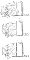
- the figures 4, 5, 6 and 7 show schematically a finishing operation on the bead 4 which has for its object to press inward the first part 5 in its peripheral zone lying furthest to the outside.
- a profile roller 12 rotatably supported by rotation bearings 20 and a pressing roller 13.
- the latter has a pressing surface 14 the shape of which corresponds with the portion of the first part 5 of the bead 4 connecting to the wall 3.
- the pressing roller 13 can be moved toward the profile roller 12 whereby the first part 5 comes into engagement in its peripheral zone 16 lying furthest to the outside with a modelling surface 17, the profiled shape of which can be seen in figures 4, 5 and 6.
- FIGS 5 and 6 show that the peripheral zone 16 has obtained a shape which corresponds with the shape of the modelling surface 17.
- the peripheral zone is therefore designated with 16' in figures 5 and 6. It is apparent that this peripheral zone has an inwardly pressed portion 18.
- Figure 7 shows very schematically a rotatably arranged positioning member 18 with clamps 19 for fixedly holding the can 1 for rotation around its axis.
- the profile roller 12 and the pressing roller 13 engage onto the bead 4 through at least one revolution.
- the profile roller 12 has two identical modelling surfaces 17, 21.
- the profile roller 12 can hereby be used twice if desired.
Landscapes
- Engineering & Computer Science (AREA)
- Mechanical Engineering (AREA)
- Rigid Containers With Two Or More Constituent Elements (AREA)
- Gasket Seals (AREA)
- Table Devices Or Equipment (AREA)
- Sheet Holders (AREA)
- Closures For Containers (AREA)
- Sealing Devices (AREA)
- Pressure Vessels And Lids Thereof (AREA)
- Medicines That Contain Protein Lipid Enzymes And Other Medicines (AREA)
Abstract
Description
- The invention relates to a metal can comprising a bottom and a standing wall which is connected thereto and whereof the zone remote from the bottom comprises an outwardly extending bead having in cross section a first part extending through about 360°, a second part lying against the first part and extending through about 90°-120° and a third part connecting thereto with a considerably smaller radius of curvature. Such a can is known. It is designed to be closed by means of a lid that co-acts clampingly with the bead. To improve reliable closure of the can by means of the lid use is made of a closing ring which grips around the top edge of the lid and the bottom edge of the bead. Reference is made in this respect to applicant's Netherlands patent application which is being filed with the Dutch Patent Office on the same day as the present application and bears the title "Closing ring for a metal can with a lid".
- The object of the invention is to improve the reliability of the closure as far as possible. Since it is known that a bead tends to continuously deform, the invention proposes means for preventing this tendency so that a can once closed in the manner described preserves its tightly closed state.
- With a view hereto the invention provides a can of the type described which has the feature that the first part is pressed inward in its most outwardly located peripheral zone. The inward pressed peripheral zone also provides an action comparable to the action of a hooking edge, while the advantage is also achieved that the bead has an increased rigidity or, if the rigidity is to remain constant, can be manufactured from a smaller quantity of material. The inward pressed peripheral zone can be obtained by techniques per se known from the metal working art and mechanical engineering, such as performing a deforming operation by means of moulds or performing a rolling operation. A rolling operation can have the advantage that through a number of deforming cycles the degree of deforming per cycle can remain limited. Use can for example be made of a set of rollers placed on one deforming station.
- The can according to the invention preferably has the feature that the second part extends through about 90°.
- A considerable improvement of the rigidity is obtained with an embodiment in which the inward pressed zone is pressed against the third part.
- The rigidity is particularly stimulated with a variant in which the inward pressed zone is pressed against the third part such that the third part is correspondingly deformed and presses against the zone over a considerable surface.
- In a preferred embodiment the can has the feature that the inward pressed zone is flat in cross section.
- It has been found to be technically advantageous if the middle of the inward pressed zone is situated above the middle of the first part.
- In this latter case the variant is advantageous in which the zone situated beneath the inward pressed zone extends further outward than the zone situated above the inward pressed zone.
- The can preferably has the feature that the portion of the bead facing toward the standing wall is substantially arcuate in cross section through about 180°.
- The bottom surface and the top surface in axial direction of the bead can be substantially flat.
- In particular the flat underside in combination with the relatively small radius of curvature of the bead portion connecting thereto assists the good gripping of the lid and the closing band onto the bead.
- It is noted that the height of the bead can be equal to the height of the bead normally in use up to the present time. Thus achieved here is that no further alterations in the setting of machines is necessary.
- The invention will now be elucidated with reference to the annexed drawing, in which:
- figure 1 shows a paint can of the so-called conical type with a closing lid drawn at a distance therefrom and around which a closing ring is arranged;
- figure 2 shows the paint can according to figure 1 in the situation in which the lid is placed on the can and the underside of the closing ring is pressed inward to form a sealing;
- figure 3 shows on enlarged scale the detail III in cross section, wherein it is noted that the bead is of the known type;
- figure 4 shows a detail of a machining device for forming the can according to the invention in a phase in which the bead is placed but not yet deformed;
- figure 5 shows a view corresponding with figure 4 of the situation in which the deforming operation has taken place;
- figure 6 shows a partially broken away perspective view corresponding to the cross section of figure 5 and showing that the bead is deformed by means of deforming rollers; and
- figure 7 is a very schematic perspective view of the deforming operation according to the figures 4, 5 and 6.
- Figure 1 shows a metal can 1 according to the prior art comprising a bottom 2 and, connected thereto, a standing
wall 3 in which the zone remote from the bottom 2 comprises an outward extending bead 4 (also see figure 3) having in section a first part 5 extending through about 360°, a second part 6 lying against the first part 5 and extending through about 90°-120° and a third part 7 connecting thereto with a considerably smaller radius of curvature. - Figure 1 shows the
can 1 before it is closed by alid 8. - Figure 2 shows the
can 1 after it has been closed by thelid 8. - Figure 3 shows the manner in which the
lid 8 co-acts with thecan 1. A filler mass orcompound 10 is situated between therim 9 of thelid 8 and the top surface of the bead 4. This mass serves to seal thelid 8 relative to thecan 1. - After the
lid 8 is placed on thecan 1 the connection is reinforced by means of anencircling closing band 11. This grips around therim 9 and the bead 4 as figure 3 clearly shows. - The figures 4, 5, 6 and 7 show schematically a finishing operation on the bead 4 which has for its object to press inward the first part 5 in its peripheral zone lying furthest to the outside.
- Use is made for this purpose of two co-acting rollers which can be carried toward one another, respectively a
profile roller 12 rotatably supported byrotation bearings 20 and apressing roller 13. The latter has apressing surface 14 the shape of which corresponds with the portion of the first part 5 of the bead 4 connecting to thewall 3. As indicated with an arrow 15, thepressing roller 13 can be moved toward theprofile roller 12 whereby the first part 5 comes into engagement in itsperipheral zone 16 lying furthest to the outside with amodelling surface 17, the profiled shape of which can be seen in figures 4, 5 and 6. - Figures 5 and 6 show that the
peripheral zone 16 has obtained a shape which corresponds with the shape of themodelling surface 17. The peripheral zone is therefore designated with 16' in figures 5 and 6. It is apparent that this peripheral zone has an inwardly pressedportion 18. - Figure 7 shows very schematically a rotatably arranged positioning
member 18 withclamps 19 for fixedly holding thecan 1 for rotation around its axis. Theprofile roller 12 and thepressing roller 13 engage onto the bead 4 through at least one revolution. - Per se known drive means are not drawn here.
- The
profile roller 12 has twoidentical modelling surfaces profile roller 12 can hereby be used twice if desired.
Claims (9)
- Metal can, comprising a bottom (2) and a standing wall (3) which is connected thereto and whereof the zone remote from the bottom comprises an outwardly extending bead (4) having in cross section a first part (5) extending through about 360°, a second part (6) lying against the first part and extending through about 90°-120° and a third part (7) connecting thereto with a considerably smaller radius of curvature,
characterized in that
the first part is pressed inward in its peripheral zone lying furthest to the outside. - Can as claimed in claim 1, characterized in that the second part extends through about 90°.
- Can as claimed in claim 1, characterized in that the inward pressed zone is pressed against the third part.
- Can as claimed in claim 3, characterized in that the inward pressed zone is pressed against the third part such that this third part is correspondingly deformed and presses against the zone over a considerable surface.
- Can as claimed in claim 1, characterized in that the inward pressed zone is flat in cross section.
- Can as claimed in claim 1, characterized in that the middle of the inward pressed zone is situated above the middle of the first part.
- Can as claimed in claim 6, characterized in that the zone situated beneath the inward pressed zone extends further outward than the zone situated above the inward pressed zone.
- Can as claimed in claim 1, characterized in that the portion of the bead facing toward the standing wall has a substantially arcuate cross section through about 180°.
- Can as claimed in claim 1, characterized in that the underside and/or the upper part of the bead is substantially flat.
Applications Claiming Priority (2)
| Application Number | Priority Date | Filing Date | Title |
|---|---|---|---|
| NL9100915A NL9100915A (en) | 1991-05-28 | 1991-05-28 | METAL BUSH WITH A BEADED EDGE. |
| NL9100915 | 1991-05-28 |
Publications (2)
| Publication Number | Publication Date |
|---|---|
| EP0516204A1 EP0516204A1 (en) | 1992-12-02 |
| EP0516204B1 true EP0516204B1 (en) | 1995-08-16 |
Family
ID=19859291
Family Applications (1)
| Application Number | Title | Priority Date | Filing Date |
|---|---|---|---|
| EP92201254A Expired - Lifetime EP0516204B1 (en) | 1991-05-28 | 1992-05-05 | Metal can having a bead |
Country Status (7)
| Country | Link |
|---|---|
| EP (1) | EP0516204B1 (en) |
| AT (1) | ATE126495T1 (en) |
| DE (1) | DE69204104T2 (en) |
| DK (1) | DK0516204T3 (en) |
| ES (1) | ES2075593T3 (en) |
| GR (1) | GR3017566T3 (en) |
| NL (1) | NL9100915A (en) |
Families Citing this family (1)
| Publication number | Priority date | Publication date | Assignee | Title |
|---|---|---|---|---|
| NL1000121C2 (en) * | 1995-04-11 | 1996-10-14 | Thomassen & Drijver | Combination of a metal can and a lid. |
Family Cites Families (3)
| Publication number | Priority date | Publication date | Assignee | Title |
|---|---|---|---|---|
| DE1008600B (en) * | 1953-09-21 | 1957-05-16 | Paul Reese | Closure for by flat lids or the like. Lockable vessels, containers or the like. |
| FR2187447B1 (en) * | 1972-06-05 | 1974-12-27 | Cebal Gp | |
| DE3714890A1 (en) * | 1987-05-05 | 1988-12-01 | Muhr & Soehne | Container with non-removable lid |
-
1991
- 1991-05-28 NL NL9100915A patent/NL9100915A/en not_active Application Discontinuation
-
1992
- 1992-05-05 DE DE69204104T patent/DE69204104T2/en not_active Expired - Fee Related
- 1992-05-05 EP EP92201254A patent/EP0516204B1/en not_active Expired - Lifetime
- 1992-05-05 DK DK92201254.7T patent/DK0516204T3/en active
- 1992-05-05 ES ES92201254T patent/ES2075593T3/en not_active Expired - Lifetime
- 1992-05-05 AT AT92201254T patent/ATE126495T1/en not_active IP Right Cessation
-
1995
- 1995-09-28 GR GR950402679T patent/GR3017566T3/en unknown
Also Published As
| Publication number | Publication date |
|---|---|
| EP0516204A1 (en) | 1992-12-02 |
| NL9100915A (en) | 1992-12-16 |
| ATE126495T1 (en) | 1995-09-15 |
| DE69204104D1 (en) | 1995-09-21 |
| ES2075593T3 (en) | 1995-10-01 |
| DK0516204T3 (en) | 1995-10-02 |
| DE69204104T2 (en) | 1996-01-04 |
| GR3017566T3 (en) | 1995-12-31 |
Similar Documents
| Publication | Publication Date | Title |
|---|---|---|
| US6442991B1 (en) | Device for stretching and molding can bodies | |
| GB2023555A (en) | Container closure | |
| US4328905A (en) | Metal can with membrane type closure | |
| US5143504A (en) | Method of manufacturing a seam connection | |
| US5020955A (en) | Method of manufacturing a closure unit made of sheet metal or plating and container having a closure unit obtained thereby | |
| CA2212228A1 (en) | Method and apparatus for forming drink-thru cup lids | |
| US4316318A (en) | Method of mounting mouthpiece device of drums and like containers | |
| WO2000002791A1 (en) | Dual function overcap | |
| ES296893U (en) | Method of curling can lids onto a can body. | |
| US3680350A (en) | Necking-in die pilot | |
| GB2102775A (en) | Closure caps and methods and tools for the production thereof | |
| EP0516204A1 (en) | Metal can having a bead | |
| US4205761A (en) | Tensioning hoop fastening means | |
| DE3464703D1 (en) | Method of cramping a metallic cover | |
| US5054637A (en) | Can end for a tubular container | |
| US3472417A (en) | Method of making window can closures | |
| CA2204459A1 (en) | A container and end closure adapted for evacuating and back-flushing of gases during closing | |
| IT8368160A1 (en) | PACKAGING, ESPECIALLY A CONTAINER IN THE FORM OF A CAN OR SIMILAR. | |
| JPH0386337A (en) | Multiple seaming matching provided with expanding chuck and method for multiple seaming | |
| EP0356874B1 (en) | Metal containers | |
| JPS6135814Y2 (en) | ||
| US1823046A (en) | Container | |
| JPH0132112B2 (en) | ||
| US579241A (en) | Automatic-sealing sheet-metal can | |
| JPH0475095B2 (en) |
Legal Events
| Date | Code | Title | Description |
|---|---|---|---|
| PUAI | Public reference made under article 153(3) epc to a published international application that has entered the european phase |
Free format text: ORIGINAL CODE: 0009012 |
|
| AK | Designated contracting states |
Kind code of ref document: A1 Designated state(s): AT BE CH DE DK ES FR GB GR IT LI LU MC NL PT SE |
|
| 17P | Request for examination filed |
Effective date: 19930602 |
|
| 17Q | First examination report despatched |
Effective date: 19940720 |
|
| ITF | It: translation for a ep patent filed | ||
| GRAA | (expected) grant |
Free format text: ORIGINAL CODE: 0009210 |
|
| AK | Designated contracting states |
Kind code of ref document: B1 Designated state(s): AT BE CH DE DK ES FR GB GR IT LI LU MC NL PT SE |
|
| REF | Corresponds to: |
Ref document number: 126495 Country of ref document: AT Date of ref document: 19950915 Kind code of ref document: T |
|
| REF | Corresponds to: |
Ref document number: 69204104 Country of ref document: DE Date of ref document: 19950921 |
|
| ET | Fr: translation filed | ||
| REG | Reference to a national code |
Ref country code: ES Ref legal event code: FG2A Ref document number: 2075593 Country of ref document: ES Kind code of ref document: T3 |
|
| REG | Reference to a national code |
Ref country code: DK Ref legal event code: T3 |
|
| REG | Reference to a national code |
Ref country code: GR Ref legal event code: FG4A Free format text: 3017566 |
|
| PLBE | No opposition filed within time limit |
Free format text: ORIGINAL CODE: 0009261 |
|
| STAA | Information on the status of an ep patent application or granted ep patent |
Free format text: STATUS: NO OPPOSITION FILED WITHIN TIME LIMIT |
|
| 26N | No opposition filed | ||
| PGFP | Annual fee paid to national office [announced via postgrant information from national office to epo] |
Ref country code: LU Payment date: 19980828 Year of fee payment: 7 |
|
| PGFP | Annual fee paid to national office [announced via postgrant information from national office to epo] |
Ref country code: GR Payment date: 19980831 Year of fee payment: 7 |
|
| PGFP | Annual fee paid to national office [announced via postgrant information from national office to epo] |
Ref country code: MC Payment date: 19980918 Year of fee payment: 7 |
|
| PG25 | Lapsed in a contracting state [announced via postgrant information from national office to epo] |
Ref country code: LU Free format text: LAPSE BECAUSE OF NON-PAYMENT OF DUE FEES Effective date: 19990505 |
|
| PG25 | Lapsed in a contracting state [announced via postgrant information from national office to epo] |
Ref country code: GR Free format text: LAPSE BECAUSE OF NON-PAYMENT OF DUE FEES Effective date: 19990531 |
|
| PG25 | Lapsed in a contracting state [announced via postgrant information from national office to epo] |
Ref country code: MC Free format text: LAPSE BECAUSE OF NON-PAYMENT OF DUE FEES Effective date: 19991130 |
|
| REG | Reference to a national code |
Ref country code: GB Ref legal event code: IF02 |
|
| PGFP | Annual fee paid to national office [announced via postgrant information from national office to epo] |
Ref country code: DK Payment date: 20080530 Year of fee payment: 17 Ref country code: ES Payment date: 20080530 Year of fee payment: 17 Ref country code: CH Payment date: 20080529 Year of fee payment: 17 Ref country code: DE Payment date: 20080530 Year of fee payment: 17 |
|
| PGFP | Annual fee paid to national office [announced via postgrant information from national office to epo] |
Ref country code: AT Payment date: 20080528 Year of fee payment: 17 |
|
| PGFP | Annual fee paid to national office [announced via postgrant information from national office to epo] |
Ref country code: BE Payment date: 20080529 Year of fee payment: 17 |
|
| PGFP | Annual fee paid to national office [announced via postgrant information from national office to epo] |
Ref country code: SE Payment date: 20080530 Year of fee payment: 17 Ref country code: NL Payment date: 20080531 Year of fee payment: 17 |
|
| PGFP | Annual fee paid to national office [announced via postgrant information from national office to epo] |
Ref country code: FR Payment date: 20080527 Year of fee payment: 17 Ref country code: IT Payment date: 20080529 Year of fee payment: 17 |
|
| PGFP | Annual fee paid to national office [announced via postgrant information from national office to epo] |
Ref country code: GB Payment date: 20080530 Year of fee payment: 17 |
|
| PGFP | Annual fee paid to national office [announced via postgrant information from national office to epo] |
Ref country code: PT Payment date: 20090428 Year of fee payment: 18 |
|
| BERE | Be: lapsed |
Owner name: *THOMASSEN & DRIJVER-VERBLIFA N.V. Effective date: 20090531 |
|
| REG | Reference to a national code |
Ref country code: CH Ref legal event code: PL |
|
| REG | Reference to a national code |
Ref country code: DK Ref legal event code: EBP |
|
| GBPC | Gb: european patent ceased through non-payment of renewal fee |
Effective date: 20090505 |
|
| PG25 | Lapsed in a contracting state [announced via postgrant information from national office to epo] |
Ref country code: AT Free format text: LAPSE BECAUSE OF NON-PAYMENT OF DUE FEES Effective date: 20090505 Ref country code: CH Free format text: LAPSE BECAUSE OF NON-PAYMENT OF DUE FEES Effective date: 20090531 Ref country code: LI Free format text: LAPSE BECAUSE OF NON-PAYMENT OF DUE FEES Effective date: 20090531 |
|
| NLV4 | Nl: lapsed or anulled due to non-payment of the annual fee |
Effective date: 20091201 |
|
| PG25 | Lapsed in a contracting state [announced via postgrant information from national office to epo] |
Ref country code: NL Free format text: LAPSE BECAUSE OF NON-PAYMENT OF DUE FEES Effective date: 20091201 |
|
| REG | Reference to a national code |
Ref country code: FR Ref legal event code: ST Effective date: 20100129 |
|
| PG25 | Lapsed in a contracting state [announced via postgrant information from national office to epo] |
Ref country code: FR Free format text: LAPSE BECAUSE OF NON-PAYMENT OF DUE FEES Effective date: 20090602 Ref country code: DK Free format text: LAPSE BECAUSE OF NON-PAYMENT OF DUE FEES Effective date: 20090531 |
|
| PG25 | Lapsed in a contracting state [announced via postgrant information from national office to epo] |
Ref country code: GB Free format text: LAPSE BECAUSE OF NON-PAYMENT OF DUE FEES Effective date: 20090505 |
|
| PG25 | Lapsed in a contracting state [announced via postgrant information from national office to epo] |
Ref country code: DE Free format text: LAPSE BECAUSE OF NON-PAYMENT OF DUE FEES Effective date: 20091201 Ref country code: BE Free format text: LAPSE BECAUSE OF NON-PAYMENT OF DUE FEES Effective date: 20090531 |
|
| REG | Reference to a national code |
Ref country code: ES Ref legal event code: FD2A Effective date: 20090506 |
|
| PG25 | Lapsed in a contracting state [announced via postgrant information from national office to epo] |
Ref country code: ES Free format text: LAPSE BECAUSE OF NON-PAYMENT OF DUE FEES Effective date: 20090506 |
|
| REG | Reference to a national code |
Ref country code: PT Ref legal event code: MM4A Free format text: LAPSE DUE TO NON-PAYMENT OF FEES Effective date: 20101105 |
|
| PG25 | Lapsed in a contracting state [announced via postgrant information from national office to epo] |
Ref country code: PT Free format text: LAPSE BECAUSE OF NON-PAYMENT OF DUE FEES Effective date: 20101105 |
|
| PG25 | Lapsed in a contracting state [announced via postgrant information from national office to epo] |
Ref country code: IT Free format text: LAPSE BECAUSE OF NON-PAYMENT OF DUE FEES Effective date: 20090505 |
|
| PG25 | Lapsed in a contracting state [announced via postgrant information from national office to epo] |
Ref country code: SE Free format text: LAPSE BECAUSE OF NON-PAYMENT OF DUE FEES Effective date: 20090506 |