EP0515744B1 - Verfahren zum Transportieren von Eisenschwamm - Google Patents
Verfahren zum Transportieren von Eisenschwamm Download PDFInfo
- Publication number
- EP0515744B1 EP0515744B1 EP91304911A EP91304911A EP0515744B1 EP 0515744 B1 EP0515744 B1 EP 0515744B1 EP 91304911 A EP91304911 A EP 91304911A EP 91304911 A EP91304911 A EP 91304911A EP 0515744 B1 EP0515744 B1 EP 0515744B1
- Authority
- EP
- European Patent Office
- Prior art keywords
- gas
- iron
- dri
- particles
- further characterised
- Prior art date
- Legal status (The legal status is an assumption and is not a legal conclusion. Google has not performed a legal analysis and makes no representation as to the accuracy of the status listed.)
- Expired - Lifetime
Links
- XEEYBQQBJWHFJM-UHFFFAOYSA-N Iron Chemical compound [Fe] XEEYBQQBJWHFJM-UHFFFAOYSA-N 0.000 title claims abstract description 145
- 229910052742 iron Inorganic materials 0.000 title claims abstract description 70
- 238000000034 method Methods 0.000 title claims abstract description 32
- 239000007789 gas Substances 0.000 claims abstract description 107
- 230000009467 reduction Effects 0.000 claims abstract description 48
- 238000003860 storage Methods 0.000 claims abstract description 15
- 229910000831 Steel Inorganic materials 0.000 claims abstract description 13
- 238000012545 processing Methods 0.000 claims abstract description 13
- 239000010959 steel Substances 0.000 claims abstract description 13
- QVGXLLKOCUKJST-UHFFFAOYSA-N atomic oxygen Chemical compound [O] QVGXLLKOCUKJST-UHFFFAOYSA-N 0.000 claims abstract description 12
- 239000001301 oxygen Substances 0.000 claims abstract description 12
- 229910052760 oxygen Inorganic materials 0.000 claims abstract description 12
- 239000007787 solid Substances 0.000 claims abstract description 10
- 239000002245 particle Substances 0.000 claims description 80
- VNWKTOKETHGBQD-UHFFFAOYSA-N methane Chemical group C VNWKTOKETHGBQD-UHFFFAOYSA-N 0.000 claims description 22
- 239000003345 natural gas Substances 0.000 claims description 11
- IJGRMHOSHXDMSA-UHFFFAOYSA-N Atomic nitrogen Chemical compound N#N IJGRMHOSHXDMSA-UHFFFAOYSA-N 0.000 claims description 9
- 238000001816 cooling Methods 0.000 claims description 9
- CURLTUGMZLYLDI-UHFFFAOYSA-N Carbon dioxide Chemical compound O=C=O CURLTUGMZLYLDI-UHFFFAOYSA-N 0.000 claims description 5
- 230000001105 regulatory effect Effects 0.000 claims description 5
- 238000004140 cleaning Methods 0.000 claims description 4
- 238000002485 combustion reaction Methods 0.000 claims description 4
- 229910052757 nitrogen Inorganic materials 0.000 claims description 4
- 229910002092 carbon dioxide Inorganic materials 0.000 claims description 3
- 238000007599 discharging Methods 0.000 claims description 3
- 239000000446 fuel Substances 0.000 claims description 3
- 238000002844 melting Methods 0.000 claims description 3
- 230000008018 melting Effects 0.000 claims description 3
- 238000004064 recycling Methods 0.000 claims description 3
- 238000007789 sealing Methods 0.000 claims description 3
- 238000000926 separation method Methods 0.000 claims description 3
- 239000001569 carbon dioxide Substances 0.000 claims description 2
- 230000001419 dependent effect Effects 0.000 claims description 2
- 238000010438 heat treatment Methods 0.000 claims 5
- 230000001131 transforming effect Effects 0.000 claims 2
- 238000004891 communication Methods 0.000 claims 1
- 230000001276 controlling effect Effects 0.000 claims 1
- 230000003647 oxidation Effects 0.000 claims 1
- 238000007254 oxidation reaction Methods 0.000 claims 1
- 238000012358 sourcing Methods 0.000 claims 1
- 239000012159 carrier gas Substances 0.000 abstract description 27
- 238000009628 steelmaking Methods 0.000 abstract description 10
- 238000010891 electric arc Methods 0.000 abstract description 9
- 238000011946 reduction process Methods 0.000 abstract description 6
- 230000006698 induction Effects 0.000 abstract description 2
- 239000013067 intermediate product Substances 0.000 abstract description 2
- UQSXHKLRYXJYBZ-UHFFFAOYSA-N iron oxide Inorganic materials [Fe]=O UQSXHKLRYXJYBZ-UHFFFAOYSA-N 0.000 abstract description 2
- 235000013980 iron oxide Nutrition 0.000 abstract description 2
- VBMVTYDPPZVILR-UHFFFAOYSA-N iron(2+);oxygen(2-) Chemical class [O-2].[Fe+2] VBMVTYDPPZVILR-UHFFFAOYSA-N 0.000 abstract description 2
- 239000007788 liquid Substances 0.000 abstract description 2
- 238000005265 energy consumption Methods 0.000 abstract 1
- 239000003570 air Substances 0.000 description 23
- 239000008188 pellet Substances 0.000 description 12
- 230000008901 benefit Effects 0.000 description 6
- 238000004519 manufacturing process Methods 0.000 description 6
- 238000010405 reoxidation reaction Methods 0.000 description 6
- 238000005299 abrasion Methods 0.000 description 5
- 239000000203 mixture Substances 0.000 description 5
- 239000000112 cooling gas Substances 0.000 description 4
- 238000009825 accumulation Methods 0.000 description 3
- 230000009257 reactivity Effects 0.000 description 3
- XLYOFNOQVPJJNP-UHFFFAOYSA-N water Substances O XLYOFNOQVPJJNP-UHFFFAOYSA-N 0.000 description 3
- 235000008733 Citrus aurantifolia Nutrition 0.000 description 2
- 235000011941 Tilia x europaea Nutrition 0.000 description 2
- 239000012080 ambient air Substances 0.000 description 2
- 230000015572 biosynthetic process Effects 0.000 description 2
- 239000003054 catalyst Substances 0.000 description 2
- 230000003197 catalytic effect Effects 0.000 description 2
- 238000006243 chemical reaction Methods 0.000 description 2
- 230000007423 decrease Effects 0.000 description 2
- 238000003912 environmental pollution Methods 0.000 description 2
- 239000011261 inert gas Substances 0.000 description 2
- 238000009434 installation Methods 0.000 description 2
- 239000004571 lime Substances 0.000 description 2
- 238000012423 maintenance Methods 0.000 description 2
- 238000012986 modification Methods 0.000 description 2
- 230000004048 modification Effects 0.000 description 2
- 230000008569 process Effects 0.000 description 2
- 239000011343 solid material Substances 0.000 description 2
- 239000000126 substance Substances 0.000 description 2
- 238000012546 transfer Methods 0.000 description 2
- UGFAIRIUMAVXCW-UHFFFAOYSA-N Carbon monoxide Chemical compound [O+]#[C-] UGFAIRIUMAVXCW-UHFFFAOYSA-N 0.000 description 1
- UFHFLCQGNIYNRP-UHFFFAOYSA-N Hydrogen Chemical compound [H][H] UFHFLCQGNIYNRP-UHFFFAOYSA-N 0.000 description 1
- 235000019738 Limestone Nutrition 0.000 description 1
- 239000006096 absorbing agent Substances 0.000 description 1
- 239000000654 additive Substances 0.000 description 1
- 229910002091 carbon monoxide Inorganic materials 0.000 description 1
- 238000005056 compaction Methods 0.000 description 1
- 239000012141 concentrate Substances 0.000 description 1
- 230000003247 decreasing effect Effects 0.000 description 1
- 230000006866 deterioration Effects 0.000 description 1
- 239000010459 dolomite Substances 0.000 description 1
- 229910000514 dolomite Inorganic materials 0.000 description 1
- 230000000694 effects Effects 0.000 description 1
- 238000002474 experimental method Methods 0.000 description 1
- 238000005194 fractionation Methods 0.000 description 1
- 238000000227 grinding Methods 0.000 description 1
- 231100001261 hazardous Toxicity 0.000 description 1
- 229910052595 hematite Inorganic materials 0.000 description 1
- 239000011019 hematite Substances 0.000 description 1
- 239000001257 hydrogen Substances 0.000 description 1
- 229910052739 hydrogen Inorganic materials 0.000 description 1
- LIKBJVNGSGBSGK-UHFFFAOYSA-N iron(3+);oxygen(2-) Chemical compound [O-2].[O-2].[O-2].[Fe+3].[Fe+3] LIKBJVNGSGBSGK-UHFFFAOYSA-N 0.000 description 1
- SZVJSHCCFOBDDC-UHFFFAOYSA-N iron(II,III) oxide Inorganic materials O=[Fe]O[Fe]O[Fe]=O SZVJSHCCFOBDDC-UHFFFAOYSA-N 0.000 description 1
- 239000006028 limestone Substances 0.000 description 1
- 239000000463 material Substances 0.000 description 1
- 238000003801 milling Methods 0.000 description 1
- JCXJVPUVTGWSNB-UHFFFAOYSA-N nitrogen dioxide Inorganic materials O=[N]=O JCXJVPUVTGWSNB-UHFFFAOYSA-N 0.000 description 1
- 230000036961 partial effect Effects 0.000 description 1
- 238000005453 pelletization Methods 0.000 description 1
- 239000003208 petroleum Substances 0.000 description 1
- 239000000843 powder Substances 0.000 description 1
- 230000001681 protective effect Effects 0.000 description 1
- 230000002829 reductive effect Effects 0.000 description 1
- 238000007670 refining Methods 0.000 description 1
- 238000009877 rendering Methods 0.000 description 1
- 230000000717 retained effect Effects 0.000 description 1
- 230000000630 rising effect Effects 0.000 description 1
- 238000005201 scrubbing Methods 0.000 description 1
- 230000035939 shock Effects 0.000 description 1
- 239000007779 soft material Substances 0.000 description 1
- 238000003786 synthesis reaction Methods 0.000 description 1
- 230000007704 transition Effects 0.000 description 1
Images

Classifications
-
- C—CHEMISTRY; METALLURGY
- C21—METALLURGY OF IRON
- C21B—MANUFACTURE OF IRON OR STEEL
- C21B13/00—Making spongy iron or liquid steel, by direct processes
- C21B13/14—Multi-stage processes processes carried out in different vessels or furnaces
- C21B13/143—Injection of partially reduced ore into a molten bath
-
- B—PERFORMING OPERATIONS; TRANSPORTING
- B65—CONVEYING; PACKING; STORING; HANDLING THIN OR FILAMENTARY MATERIAL
- B65G—TRANSPORT OR STORAGE DEVICES, e.g. CONVEYORS FOR LOADING OR TIPPING, SHOP CONVEYOR SYSTEMS OR PNEUMATIC TUBE CONVEYORS
- B65G53/00—Conveying materials in bulk through troughs, pipes or tubes by floating the materials or by flow of gas, liquid or foam
- B65G53/04—Conveying materials in bulk pneumatically through pipes or tubes; Air slides
- B65G53/06—Gas pressure systems operating without fluidisation of the materials
-
- C—CHEMISTRY; METALLURGY
- C21—METALLURGY OF IRON
- C21B—MANUFACTURE OF IRON OR STEEL
- C21B13/00—Making spongy iron or liquid steel, by direct processes
-
- C—CHEMISTRY; METALLURGY
- C21—METALLURGY OF IRON
- C21B—MANUFACTURE OF IRON OR STEEL
- C21B13/00—Making spongy iron or liquid steel, by direct processes
- C21B13/0006—Making spongy iron or liquid steel, by direct processes obtaining iron or steel in a molten state
- C21B13/0013—Making spongy iron or liquid steel, by direct processes obtaining iron or steel in a molten state introduction of iron oxide into a bath of molten iron containing a carbon reductant
- C21B13/002—Reduction of iron ores by passing through a heated column of carbon
-
- C—CHEMISTRY; METALLURGY
- C21—METALLURGY OF IRON
- C21B—MANUFACTURE OF IRON OR STEEL
- C21B13/00—Making spongy iron or liquid steel, by direct processes
- C21B13/0086—Conditioning, transformation of reduced iron ores
-
- C—CHEMISTRY; METALLURGY
- C21—METALLURGY OF IRON
- C21B—MANUFACTURE OF IRON OR STEEL
- C21B13/00—Making spongy iron or liquid steel, by direct processes
- C21B13/02—Making spongy iron or liquid steel, by direct processes in shaft furnaces
- C21B13/029—Introducing coolant gas in the shaft furnaces
-
- C—CHEMISTRY; METALLURGY
- C21—METALLURGY OF IRON
- C21B—MANUFACTURE OF IRON OR STEEL
- C21B13/00—Making spongy iron or liquid steel, by direct processes
- C21B13/14—Multi-stage processes processes carried out in different vessels or furnaces
-
- C—CHEMISTRY; METALLURGY
- C21—METALLURGY OF IRON
- C21B—MANUFACTURE OF IRON OR STEEL
- C21B2100/00—Handling of exhaust gases produced during the manufacture of iron or steel
- C21B2100/20—Increasing the gas reduction potential of recycled exhaust gases
- C21B2100/28—Increasing the gas reduction potential of recycled exhaust gases by separation
- C21B2100/282—Increasing the gas reduction potential of recycled exhaust gases by separation of carbon dioxide
-
- C—CHEMISTRY; METALLURGY
- C21—METALLURGY OF IRON
- C21B—MANUFACTURE OF IRON OR STEEL
- C21B2100/00—Handling of exhaust gases produced during the manufacture of iron or steel
- C21B2100/40—Gas purification of exhaust gases to be recirculated or used in other metallurgical processes
- C21B2100/44—Removing particles, e.g. by scrubbing, dedusting
-
- Y—GENERAL TAGGING OF NEW TECHNOLOGICAL DEVELOPMENTS; GENERAL TAGGING OF CROSS-SECTIONAL TECHNOLOGIES SPANNING OVER SEVERAL SECTIONS OF THE IPC; TECHNICAL SUBJECTS COVERED BY FORMER USPC CROSS-REFERENCE ART COLLECTIONS [XRACs] AND DIGESTS
- Y02—TECHNOLOGIES OR APPLICATIONS FOR MITIGATION OR ADAPTATION AGAINST CLIMATE CHANGE
- Y02P—CLIMATE CHANGE MITIGATION TECHNOLOGIES IN THE PRODUCTION OR PROCESSING OF GOODS
- Y02P10/00—Technologies related to metal processing
- Y02P10/10—Reduction of greenhouse gas [GHG] emissions
- Y02P10/122—Reduction of greenhouse gas [GHG] emissions by capturing or storing CO2
-
- Y—GENERAL TAGGING OF NEW TECHNOLOGICAL DEVELOPMENTS; GENERAL TAGGING OF CROSS-SECTIONAL TECHNOLOGIES SPANNING OVER SEVERAL SECTIONS OF THE IPC; TECHNICAL SUBJECTS COVERED BY FORMER USPC CROSS-REFERENCE ART COLLECTIONS [XRACs] AND DIGESTS
- Y02—TECHNOLOGIES OR APPLICATIONS FOR MITIGATION OR ADAPTATION AGAINST CLIMATE CHANGE
- Y02P—CLIMATE CHANGE MITIGATION TECHNOLOGIES IN THE PRODUCTION OR PROCESSING OF GOODS
- Y02P10/00—Technologies related to metal processing
- Y02P10/10—Reduction of greenhouse gas [GHG] emissions
- Y02P10/134—Reduction of greenhouse gas [GHG] emissions by avoiding CO2, e.g. using hydrogen
-
- Y—GENERAL TAGGING OF NEW TECHNOLOGICAL DEVELOPMENTS; GENERAL TAGGING OF CROSS-SECTIONAL TECHNOLOGIES SPANNING OVER SEVERAL SECTIONS OF THE IPC; TECHNICAL SUBJECTS COVERED BY FORMER USPC CROSS-REFERENCE ART COLLECTIONS [XRACs] AND DIGESTS
- Y02—TECHNOLOGIES OR APPLICATIONS FOR MITIGATION OR ADAPTATION AGAINST CLIMATE CHANGE
- Y02P—CLIMATE CHANGE MITIGATION TECHNOLOGIES IN THE PRODUCTION OR PROCESSING OF GOODS
- Y02P10/00—Technologies related to metal processing
- Y02P10/10—Reduction of greenhouse gas [GHG] emissions
- Y02P10/143—Reduction of greenhouse gas [GHG] emissions of methane [CH4]
Definitions
- the present invention relates to a method applicable in the production of iron and steel, wherein a direct reduction process is employed to produce an intermediate product in the form of a particulate solid, commonly known as sponge iron or Direct Reduced Iron (DRI). More particularly, the invention is characterized by the produced DRI (at least 90% of which is preferably larger than 5 mm) being pneumatically transported from the reduction reactor of said direct reduction process to a remote location for subsequent storage or processing, e.g. preferably to melting metallurgical furnaces to produce liquid iron and steel.
- DRI direct Reduced Iron
- DRI is commercially produced by direct reduction of lumps or pellets of iron ore by contacting these with a stream of reducing gas at a high temperature. Reduction is carried out in the solid state. The resulting DRI is a friable particulate solid which is very porous and reactive at high temperatures. At such elevated temperatures, it reoxidizes exothermically with water or oxygen in the ambient air.
- Iron ores employed for direct reduction are generally iron oxides: hematite and magnetite.
- the iron ore When the iron ore has a high iron content, for example above 55%, it can be economically processed by simply breaking it down to particle sizes at least 80% and preferably at least 90% of which are greater than 0.5 cm and range up to about 6 cm (i.e. 0.2 to 2.4 inches). It is also necessary that said ore has a high mechanical strength so as to withstand pressures, shocks and crushing which tend to create undesirable and excessive fines during its transport and handling. Such dust-like fines can cause considerable problems, such as uneven flow and gas channelling inside the fixed or moving bed reduction reactor. This results in unhomogeneous reduction, thus producing DRI of an inferior and uneven quality.
- pellets formed are generally spherical with the desired chemical composition needed for optimal performance in the reduction process and also in the subsequent steelmaking stage in the electric arc furnace. Since pellets have a higher iron content with a more uniform quality, they can consequently be transported over long distances by truck, rail, etc., more economically (because the unnecessary transportation of a substantial amount of gangue is avoided).
- Direct reduction plants chemically reduce iron ores by contacting the particles, which may be irregularly shaped pieces of iron ore or pellets or mixtures thereof, with a stream of reducing gas, largely composed of hydrogen and carbon monoxide, at a temperature between 850 and 1,050°C, normally at about 950°C.
- the commercial reduction reactor may be of the fixed bed or moving bed type. It is evident that in order to increase the reaction rate between the solid ore particles and the reducing gas, it is desirable that said particles be highly porous. However, this characteristic also makes DRI very reactive, since it contains a high proportion of metallic iron, which tends to reoxidize when in contact with the oxygen in air or water. As is typical of all chemical reactions, reoxidation of DRI is faster and more violent as the temperature increases. This is why DRI in the past always has most desirably been safely handled at ambient temperature and is normally cooled down inside the reduction reactor by circulating a cooling gas therethrough before it is discharged. See, for example, U.S. Patent Nos. 3,765,872; 4,046,557; 4,150,972, and Stahl u.Eisen 110(1990) No. 8.
- Cooling DRI although commonly necessary for the safe handling of the DRI to avoid reoxidation problems and to reduce the need for expensive temperature resistent pumps, valves, etc., is however disadvantageous with respect to the energy efficiency of the overall steelmaking process. Since much of the thermal energy of the DRI is lost through its cooling; therefore, it is necessary to spend more energy to heat the DRI once again in order to melt it and convert it to steel. Only some of the lost energy is usefully recovered in steam generation, in heat exchangers, and the like.
- U.S. patents 3,799,367 and 4,188,022 teach discharging DRI at a high temperature from a direct reduction reactor without cooling it down to ambient temperature. It is proposed to transport this hot DRI to its next processing step, utilizing containers which are placed at the outlets of the discharge bins of the reduction reactor. These containers are filled with an inert gas to prevent contact of hot DRI with oxygen in the air, thus avoiding reoxidation thereof.
- This transport system presents a number of disadvantages, because the containers with DRI must be moved through the plant by means of trucks or railroad equipment. This requires a maintenance system for motorized vehicles with its consequent high operating costs.
- German patent No. 3806861 teaches transport of hot DRI in a bin. Such bins are used with pressure locks in some direct reduction processes operating at pressures over one atmosphere. These processes require pressure locks for charge and discharge of the reduction reactor. This transport system is however applicable only to short distances, for example from the reduction reactor to a briquetting press located close to said reactor. If DRI is to be transported over longer distances, for example hundreds of meters, this system using pressure lock bins is not practical nor economical since it would require a larger number of such bins, which, due to their required characteristics for pressure, temperature and abrasion resistance as well as their sealing valves, are expensive.
- Non-commercialized attempts to produce DRI by fluidized bed direct reduction methods have been proposed from time-to-time. These teach the use of very fine-grained ores up to only 3 mm in diameter and preferably less than 0.5 mm).
- pneumatic transport of such "fine-grained sponge iron” see U.S. Patents 4,007,034, 4,045,214, DE 3201608-A and EP-A-021222.
- U.S. Patent 4,412,858 is the only reference known to applicants which is relevant to the commercially-proven larger-sized DRI particles (i.e. greater than 0.5 cm) that has any suggestion of pneumatic transport of DRI.
- this latter patent's teaching is only in the context of the larger "sponge iron pellets [being] . . . converted to finely divided form" by "grinding or milling" prior to transport by a carrier gas.
- Crushed limestone is reported to have been pneumatically transported over short distances as a feed device; however, this is a relatively soft material as compared to DRI (or even to iron ore). Thus, in spite of such uses, such lime transport has never been extended to or suggested for iron ore or for DRI of a size greater than 3 mm.
- a method of transporting iron-bearing particles from a departure point to a remote point for storage or further processing comprising introducing said iron-bearing particles into a closed conduit, causing a stream of gas to transport pneumatically the iron-bearing particles through the closed conduit to said remote point, and separating said gas from said particles at said remote point, characterised in that at least 80% of the iron-bearing particles are of a size greater than 0.5 cm and at least 50% are of a size greater than 1.0 cm, the iron-bearing particles being introduced into said conduit when they are hot, the gas stream being substantially non-oxidising.
- the particles are introduced into the closed conduit at a temperature of at least 400°C.
- the invention provides a method of transporting hot iron-bearing particles such as iron ore or sponge iron, from a departure point to a remote point for storage or further processing, comprising introducing said iron-bearing particles into a closed conduit, causing a stream of gas to transport pneumatically the iron-bearing particles through the closed conduit to said remote point, and separating said gas from said particles at said remote point, characterised in that at least 80% of the iron- bearing particles are of a size greater than 0.5 cm and at least 50% are of a size greater than 1.0 cm, the iron-bearing particles being introduced into said conduit at a temperature above 400°C.
- the invention also provides an iron processing plant comprising a transport system for iron-bearing particles, said system including a closed conduit, introducing means for introducing said particles into the conduit at a departure point, means for passing a gas stream through the conduit with flow characteristics such as to transport pneumatically the iron-bearing particles through the conduit from the departure point to a remote point, and means for delivering said particles from the conduit at the remote point, the plant further comprising a direct reduction reactor adapted to provide hot iron-bearing particles, 80% of which particles are of a size greater than 0.5 cm and at least 50% of which are of a size greater than 1.0 cm, said reactor being arranged to deliver the particles uncooled to the introducing means, the means for passing a gas stream being arranged to utilise a substantially non oxidising gas as said gas stream. and apparatus for receiving the iron bearing particles at the remote point for storage or further processing.
- the reactor may be a vertical shaft moving bed reduction reactor with a reduction zone and a discharge zone;
- the invention in its preferred form achieves a method for the production of iron and steel wherein hot DRI of a size largely over 0.5 cm is pneumatically transported.
- This preferably comprises producing said DRI in at least one direct reduction reactor and transporting such DRI pneumatically by means of a non-oxidising carrier gas caused to flow through a duct extending from a first point (at the discharge into said duct of said DRI from said reduction reactor) to a second point (of remote use or storage of the DRI).
- Said gas stream may have a variety of chemical compositions. For example, exhausted air, natural gas, synthesis gas or reducing gas of the same type used for DRI production may be utilized.
- Pneumatic transport of DRI is preferably carried out at a carrier gas velocity in the range of 9 to 35 m/sec., at a pressure of between 1 and 5 kg/cm 2 , and at a ratio of mass of DRI to mass of carrier gas between 7 and 25.
- the gas stream is air which has been contained and recirculated.
- the problems and drawbacks of hot transportation of commercial DRI in steelmaking plants have not heretofore been satisfactorily solved.
- the present invention effectively minimizes these problems to great advantage, by surprisingly teaching contrary to conventional wisdom the use of pneumatic transport of DRI of a size mainly in excess of 0.5 cm in steelmaking plants, while modifying the transport operating conditions to achieve offsetting advantages of minimized reoxidation, minimized heat loss, containment against air and ground pollution, and less handling and storage requirements (thus resulting in less overall maintenance and space requirements for handling), all unexpectedly without excessive abrasion of the transport equipment and fractionation of the DRI.
- Fines from breakage lower the overall yield of the steelmaking process because their light weight causes them to be entrained in the gases that exit the electric furnaces.
- the present invention minimizes this problem due to its particular operating conditions.
- the air is surprisingly effectively used by being contained and continuously recirculated within the transport duct such that under steady state operation the comparatively small amount of oxygen initially in the air circulating in the duct reacts with DRI and through its recirculation the gas remaining in the transport duct soon becomes largely composed of nitrogen, all unexpectedly without any significant effect on the quality of the net amount of transported DRI (in spite of the initial presence of oxygen).
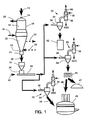
- numeral 10 generally designates a direct reduction reactor to which iron ore 12 is fed in form of lumps, pellets or mixtures thereof, through at least one inlet 14.
- the iron ore descends through the reactor 10 and is countercurrently contacted with a reducing gas at high temperature, normally in the range of 850 to 950°C, which reducing gas is introduced to the reactor at point 16 located in the lower part of the reduction zone 18, and is removed from the reactor at point 20 located in the upper part of said reduction zone, in a manner already known in the art.
- a conical section 22 which converges to at least one outlet 24 through which the already reduced ore or DRI is discharged.
- this lower zone 22 is used as cooling zone for DRI, in order to cool it down to ambient temperature for handling without reoxidation problems when in contact with the atmosphere.
- a cooling gas stream is circulated countercurrently to the DRI, which gas is introduced at the lower part thereof, as indicated by numeral 28 and is removed hot at the upper part thereof as indicated by numeral 30. Both the reducing gas and the cooling gas are recycled to the reactor as it is well known in the art.
- the cooling gas loop is not used and DRI is discharged hot.
- DRI is discharged from the reduction reactor at a rate regulated by a device 26 which may be a rotary or star valve, for example as described in U.S. patents Nos. 4,427,135 and 4,427,136, or may be other devices of the type described in U.S. patents Nos. 3,375,099; 2,670,946; 4,129,289 and 4,032,120.
- a device 26 which may be a rotary or star valve, for example as described in U.S. patents Nos. 4,427,135 and 4,427,136, or may be other devices of the type described in U.S. patents Nos. 3,375,099; 2,670,946; 4,129,289 and 4,032,120.
- DRI 32 is passed to a discharge accumulation bin 34 wherefrom it is introduced at a regulated rate into duct 38 by means of a device 36, which may be a rotary valve (also called a star feeder), a screw type feeder, or a vibratory feeder.
- a device 36 which may be a rotary valve (also called a star feeder), a screw type feeder, or a vibratory feeder.
- a gas stream 40 is caused to circulate through duct 38 to entrain and pneumatically convey the DRI to a remote point illustrated for example as (1) a storage bin or silo 42, (2) a briquetting press 44 (where briquettes 46 of DRI are formed), and/or (3) an electric arc furnace 48.
- the briquettes 46 from the press 44 may be charged to a metallurgical furnace, here illustrated as an electric arc furnace 48, or to a different type of furnace where metallic iron is melted and refined, such as induction furnaces, basic oxygen furnaces (BOF), melter-gasifiers, etc., or just to a temporary storage pile 47.
- the DRI may be transported and directly charged into the electric arc furnace as indicated by arrow 50.
- a receiving station 52 for DRI comprising a receiving bin 54 which may be used to disengage the carrier gas and the solid particles by a simple expansion of the flow area. Disengagement of the particles from the carrier gas is aided by an enlargement of the pipe 38 close to its introduction into the bin 54 (thus reducing the flow velocity).
- Carrier gas exits the receiving bin 54 and passes to a cleaning and cooling tower 56, where said gas is contacted with water in a packed bed 58, in a manner known in the art.
- the gas cleaned and at, or relatively near, ambient temperature exits the tower 56 through outlet 60.
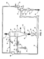
- Figure 2 shows a particularly preferred embodiment where air is used as the carrier gas which is recycled to great advantage.
- the oxygen of the initial charge of air as the carrier gas in the transport and recycle ducts (38 & 76) reacts with DRI and, when recycled, the resulting carrier gas composition very soon stabilizes to almost pure nitrogen. This characteristic makes the operation of the pneumatic transport very economical.
- a stream of air is supplied as an initial charge (and thereafter only as a make-up in small amounts) from a suitable source 70 through duct 72 and is caused to circulate in a closed circuit by compressor 74 through return duct 76 and transport duct 38 in order to convey DRI introduced to duct 38 by means of a feeder or dosifier device 36.
- DRI 50 transported from the accumulation/discharge bin 34 to the receiving/separation station 52, is then utilized in the electric arc furnace 48 to be melted and refined in said furnace 48 to produce the desired steel.
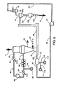
- a reducing gas from a source 80 for example produced by the catalytic reformation of natural gas with steam, is introduced through duct 82 into the reduction circuit 86 comprising the reduction zone 18 of reactor 10, a gas cooler 84, a compressor 88, a CO 2 absorber 94 and a gas heater 98.
- a portion of the reducing gas leaving compressor 88 is led through duct 92 to duct 38 to be utilized as the carrier gas for DRI introduced from the feeder 36.
- the reducing gas after having been separated from DRI at bin 54, is cooled and cleaned in gas cooler 56 and is recycled to compressor 88 via duct 90.
- DRI is introduced from bin 34 to duct 38 through a regulating device 36, and, after gas separation in bin 54, passes to lockhopper 130 which is provided with sealing valves 132 and 134 to discharge the DRI from the transport system without contact of the reducing gas with the atmosphere. See U.S. Patent Nos. 3,710,808 and 4,498,498 for such valve systems.
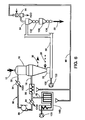
- Figure 5 shows another embodiment on the invention wherein the carrier gas is generated through the combustion of natural gas, or of any other suitable fuel, with air.
- a stream of natural gas from a suitable source 110 is introduced through duct 112 into gas generator 118 where it undergoes combustion with air from a source 114 which is introduced into generator 118 through duct 116.
- Combustion in generator 118 consumes the oxygen in the air, forming a carrier gas largely composed of nitrogen and carbon dioxide.
- This carrier gas is injected via duct 120 into the transport duct 38.
- the carrier gas discharged from scrubber 56 is recycled to the gas generator 118 or directly to the injector duct 120, thus decreasing the consumption of air and make-up fuel.
- Figure 6 shows another embodiment of the invention wherein the carrier gas utilized for pneumatic transport is natural gas which is fed, from a suitable source 122 available at a high pressure, to duct 38 through supply duct 120.
- This omission of bin 34 and discharge device 36 can be made in the embodiments in the other Figures also.
- Dosifying device 26 may be a rotary valve or star feeder, or a device of the type of a screw or vibratory, as it has been described here with reference to the previous figures.
- Natural gas once separated from DRI at bin 54, is cleaned in tower 56 and is fed to the burners for the heater 98 and the reformer 140 through return pipe 90.
- reformer 140 natural gas is caused to react with steam which are fed to said reformer from a source 123 in a manner known in the art.
- the reducing gas produced in the reformer 140 is injected into the reducing gas loop 86 through pipe 82 in order to produce the DRI in reactor 10.
- the external reformer with its sensitive catalyst tubes can be omitted and the natural gas and steam from source 123 (or possibly even 90) can feed directly into the reduction circuit 86.
- Example 2 The experiment of Example 1 was repeated, but with the 32.7 tonnes (36 US tons) of DRI being instead at ambient temperature. Operating conditions were: Gas air Pressure at inlet 1.97kg/cm 2 gauge Flow rate 75 kg mol/hr (165 lb mol/hr) Temperature 30 degrees Centigrade Gas Velocity at inlet 20 m/s Solid Material DRI pellets Temperature 35 degrees Centigrade Rate of transport 18 tonnes/hr (20 US tons/hr) SCREEN ANALYSIS Size (metric) Size (inches) (%) Initial Weight Fraction (%) Final Weight Fraction 12mm 1/2 61 25 9mm 3/8 28 51 6mm 1/4 8 16 3mm 1/8 3 7 ⁇ 3mm ⁇ 1/8 0 1 The following data were taken at the outlet point: Pressure Drop 1.8 Kg/cm 2 Pressure Atmospheric Power 9 Kw/tonnes (10 Kw/US ton) Solids/Gas ratio (mass) 15
- the experimental apparatus can empty about 36 tons of DRI in about 45 minutes and has transported DRI over 200 meters.
- DRI may be introduced into the transport duct with or without an intermediate discharge bin.
- the upper limits of the particle size to be transported should be about 7.5 cm (3 inches) and preferably no more than 1/3 the diameter of the transport pipe.
- the DRI pellets mainly are from greater than 3 mm (1/8") to 9 mm (3/4"), and DRI lumps range up to 25 mm (1") to 38 mm (11 ⁇ 2").
- the practical length of transport is 200 to 300 meters.
- typical pneumatic transport in an experimental plant from the reduction reactor to the EAF is less than a minute through a 10 cm (4") to 15 cm (6") progressively increasingly sized pipe. This gives minimal time for heat loss during transport.
- the energy loses in pneumatic transport of DRI (mainly electric cost for the compressor) are more than made up for in the savings in time, energy, and retained fines.
- Relatively lower gas velocities are preferred so as to minimize abrasion and congestion, but with sufficient velocity for efficiency of transport.
- the transport of typical DRI from a moving bed reactor generated a bell curve when the capacity of DRI conveyed was plotted against gas velocity (from about 11 tonnes of DRI/hour at a velocity of 9 meters/second, to about 23 tonnes/hr. at 20 m/s, and back down to 11 tonnes/hr at 35 m/s); thus indicating a preferred range of about 17 to 25 m/s velocity of the carrier gas.
Landscapes
- Engineering & Computer Science (AREA)
- Chemical & Material Sciences (AREA)
- Organic Chemistry (AREA)
- Manufacturing & Machinery (AREA)
- Materials Engineering (AREA)
- Metallurgy (AREA)
- Mechanical Engineering (AREA)
- Life Sciences & Earth Sciences (AREA)
- Environmental & Geological Engineering (AREA)
- General Life Sciences & Earth Sciences (AREA)
- Geochemistry & Mineralogy (AREA)
- Geology (AREA)
- Manufacture Of Iron (AREA)
- Manufacture And Refinement Of Metals (AREA)
Claims (32)
- Verfahren zum Transportieren eisenhaltiger Teilchen bzw. Eisen tragender Teilchen von einem Abtransportpunkt bzw. Ausgangspunkt zu einem entfernten Punkt zum Speichern oder Weiterverarbeiten, das das Einführen der eisenhaltigen Teilchen in eine geschlossene Leitung bzw. ein geschlossenes Rohr, das Veranlassen eines Gasstromes, um pneumatisch die eisenhaltigen Teilchen durch die geschlossene Leitung zu dem entfernten Punkt zu transportieren, und das Trennen des Gases von den Teilchen bei dem entfernten Punkt umfaßt und dadurch gekennzeichnet ist, daß wenigstens 80 % der eisenhaltigen Teilchen eine Größe von größer als 0,5 cm und wenigstens 50 % eine Größe von größer als 1,0 cm haben, wobei die eisenhaltigen Teilchen in die Leitung eingeführt werden, wenn sie heiß sind und der Gasstrom im wesentlichen nichtoxidierend ist.
- Verfahren nach Anspruch 1, das weiter dadurch gekennzeichnet ist, daß die eisenhaltigen Teilchen in die geschlossene Leitung bei einer Temperatur von wenigstens 400 °C eingeführt werden.
- Verfahren zum Transportieren eisenhaltiger Teilchen bzw. Eisen tragender Teilchen, wie z.B. Eisenerz oder Schwammeisen, von einem Abtransport- bzw. Ausgangspunkt zu einem entfernten Punkt zum Speichern und Weiterverarbeiten, das das Einführen der eisenhaltigen Teilchen in eine geschlossene Leitung, das Veranlassen eines Gasstromes, um pneumatisch die eisenhaltigen Teilchen durch die geschlossene Leitung zu dem entfernten Punkt zu transportieren, und das Trennen des Gases von den Teilchen bei dem entfernten Punkt umfaßt und dadurch gekennzeichnet ist, daß wenigstens 80 % der eisenhaltigen Teilchen eine Größe von größer als 0,5 cm und wenigstens 50 % eine Größe von größer als 1,0 cm haben, wobei die eisenhaltigen Teilchen in die Leitung bei einer Temperatur oberhalb 400 °C eingeführt werden.
- Verfahren nach Anspruch 2 oder Anspruch 3, das weiter durch eisenhaltige Teilchen gekennzeichnet ist, die in die Leitung bei einer Temperatur zwischen 450 °C und 750 °C eingeführt werden.
- Verfahren nach irgendeinem der vorhergehenden Ansprüche, das weiter durch das Zirkulieren des Gases durch die Leitung bei einer Geschwindigkeit zwischen 9 und 35 m/s und/oder bei einem Druck zwischen 1 und 5 kg/cm2 gekennzeichnet ist.
- Verfahren, wie in irgendeinem der vorhergehenden Ansprüche beansprucht, das weiter durch das Zirkulieren des Gases durch die Leitung bei einem Verhältnis der Masse der Teilchen zur Masse des Gases in dem Bereich von 7 bis 25 gekennzeichnet ist.
- Verfahren, wie in irgendeinem der vorhergehenden Ansprüche beansprucht, weiter dadurch gekennzeichnet, daß das Gas und die eisenhaltigen Teilchen, die dadurch transportiert werden, veranlaßt werden, nach oben durch einen Teil der geschlossenen Leitung zu gelangen, die sich bei einer Höhe befindet, die größer bzw. höher ist als der Ausgangspunkt.
- Verfahren, wie in irgendeinem der vorhergehenden Ansprüche beansprucht, weiter gekennzeichnet durch das Recyceln bzw. Rückführen des Gases zu dem Ausgangspunkt.
- Verfahren, wie in irgendeinem der vorhergehenden Ansprüche beansprucht, weiter dadurch gekennzeichnet, daß das Gas ursprünglich Luft oder Naturgas bzw. Erdgas oder Stickstoff oder verbrauchtes Reduziergas ist oder daß es durch die Verbrennung eines Brennstoffes bzw. Kraftstoffes mit Luft erzeugt wird.
- Verfahren, wie es im Anspruch 9 beansprucht ist, weiter dadurch gekennzeichnet, daß das Gas ursprünglich Luft ist und in einem geschlossenen Kreislauf zirkuliert wird, wobei der Sauerstoff in dem Gas durch begrenzte Oxidation von zuvor transportierten eisenhaltigen Teilchen verbraucht wird.
- Verfahren, wie in irgendeinem der vorhergehenden Ansprüche beansprucht, weiter dadurch gekennzeichnet, daß die Teilchen Schwammeisen-Teilchen (im folgenden DRI genannt) sind, die durch Direktreduktion von korpuskulärem Eisenerz in einem Reduktionsreaktor erzeugt werden und der Ausgangspunkt für das DRI sich bei dem Auslaß des Reaktors befindet.
- Verfahren, wie im Anspruch 11 beansprucht, weiter dadurch gekennzeichnet, daß das von dem Reaktor stammende noch heiße DRI in einem Schmelzofen bei dem entfernten Punkt geschmolzen und transformiert wird.
- Verfahren, wie im Anspruch 11 beansprucht, weiter dadurch gekennzeichnet, daß das DRI von dem Reduktionsreaktor bei einer Temperatur oberhalb 600 °C ausgegeben wird und das DRI zu Briketts bei dem entfernten Punkt transformiert wird.
- Verfahren, wie im Anspruch 11 beansprucht, weiter dadurch gekennzeichnet, daß das DRI in einen Speicherplatz bei dem entfernten Punkt umgeleitet wird.
- Verfahren, wie in irgendeinem der Ansprüche 11 bis 14 beansprucht, weiter dadurch gekennzeichnet, daß der Reaktor in einem Fließbett-Reduktionsreaktor oder einem Festbett-Reduktionsreaktor ist.
- Verfahren, wie in irgendeinem der Ansprüche 11 bis 15 beansprucht, weiter dadurch gekennzeichnet, daß das DRI von dem Reaktor in die Leitung durch eine Drucksperre eingeführt wird, die das Auslassen bzw. Entladen des Reduktionsreaktors ohne Kontakt mit atmosphärischer Luft bzw. Umgebungsluft mit dem inneren Teil des Reaktors erlaubt.
- Verfahren, wie in irgendeinem der Ansprüche 11 bis 15 beansprucht, weiter dadurch gekennzeichnet, daß das DRI mit einer regulierten Rate in die Leitung direkt von dem Reduktionsreaktor eingeführt wird.
- Verfahren, wie in irgendeinem der vorhergehenden Ansprüche beansprucht, weiter dadurch gekennzeichnet, daß wenigstens ein Teil des Gases nach der Trennung bei dem entfernten Punkt gekühlt, gereinigt und zu dem Ausgangspunkt zurückgeführt wird.
- Verfahren, wie in irgendeinem der Ansprüche 2 oder 11 bis 18 beansprucht, wenn sie von Anspruch 2 abhängen, dadurch gekennzeichnet, daß die eisenhaltigen Teilchen von dem Reaktor, ohne gekühlt zu werden, eingeführt werden.
- Verfahren, wie in irgendeinem vorhergehenden Anspruch beansprucht, weiter durch das Vorheizen des Gasstromes vor dem Transport der eisenhaltigen Teilchen gekennzeichnet.
- Eisenverarbeitungsanlage bzw. -fabrik, die ein Transportsystem für heiße eisenhaltige Teilchen umfaßt, wobei das System eine geschlossene Leitung (38), eine Einführeinrichtung (34) zum Einführen der Teilchen in die Leitung bei einem Ausgangspunkt, eine Einrichtung (88) zum Leiten eines Gasstromes durch die Leitung mit Fließcharakteristiken, wie z.B. den pneumatischen Transport der eisenhaltigen Teilchen durch die Leitung von dem Ausgangspunkt zu dem entfernten Punkt, und eine Einrichtung (52) zum Abgeben der Teilchen von der Leitung bei dem entfernten Punkt, umfaßt, wobei die Anlage bzw. Fabrik weiter einen direkten Reduktionsreaktor (10) umfaßt, der daran angepaßt ist, heiße eisenhaltige Teilchen bereitzustellen, von denen 80 % eine Größe aufweisen, die größer ist als 0,5 cm, und wenigstens 50 % davon eine Größe aufweisen, die größer ist als 1,0 cm, wobei der Reaktor angeordnet ist, um die Teilchen ungekühlt zu der Einführeinrichtung zu liefern, wobei die Einrichtung zum Leiten eines Gasstromes angeordnet ist, um ein im wesentlichen nichtoxidierendes Gas als den Gasstrom zu verwenden, und einen Apparat zum Aufnehmen der eisenhaltigen Teilchen bei dem entfernten Punkt zum Speichern oder Weiterverarbeiten umfaßt.
- Anlage bzw. Fabrik, wie im Anspruch 21 beansprucht, weiter dadurch gekennzeichnet, daß der Reaktor (10) angepaßt ist, um die Teilchen bei einer Temperatur von oberhalb 400 °C bereitzustellen.
- Anlage bzw. Fabrik, wie im Anspruch 21 oder 22 beansprucht, weiter gekennzeichnet durch die Einrichtung (118) zum Vorheizen des Gasstromes.
- Anlage bzw. Fabrik, wie in irgendeinem der Ansprüche 21 bis 23 beansprucht, weiter gekennzeichnet durch eine Einrichtung zum Zirkulieren des Gasstromes in einer geschlossenen Schleife.
- Anlage bzw. Fabrik, wie in irgendeinem der Ansprüche 21 bis 24 beansprucht, weiter dadurch gekennzeichnet, daß der Reaktorein Vertikalschacht-Fließbett-Reduktionsreaktor (10) mit einem Reduktionsbereich (18) und einem Entladebereich bzw. Auslaßbereich (22) ist;wobei die geschlossene Leitung eine pneumatische Röhren-Fördereinrichtung (38) für korpuskuläre Festkörper ist, der Apparat bei dem entfernten Punkt ein Teilchen-Handhabungsbunker (54) ist, der seitlich von dem Reaktor entfernt ist und vertikal bezüglich des Reaktors nicht ausgerichtet ist, die Einrichtung (74, 76 oder 88, 92 oder 96, 92 oder 91, 92) zum Leiten eines Gasstromes zum Zuführen des Gases bei einem Druck und einer Geschwindigkeit angeordnet ist, die bzw. der ausreichend ist, um die Teilchen nach oben anzuheben und sie pneumatisch zwischen dem Reaktor und dem Bunker zu transportieren.
- Anlage bzw. Fabrik, wie im Anspruch 25 beansprucht, weiter gekennzeichnet durch:einen Beschickungseinlaß (14) zu dem Reduktionsbereich;einen Entladungsauslaß (24) von dem Entladungsbereich bzw. Auslaßbereich;eine Einrichtung (26) zum Steuern des Auslasses bzw. Entladens von Teilchen (32) von dem Entladebereich durch den Auslaß;eine Einrichtung (16) zum Zuführen des heißen Reduzierungsgases am Boden des oberen Reduktionsbereiches und eine Einrichtung (20) zum Entfernen des verbrauchten Stroms von heißem Reduziergas an dem obersten Abschnitt des Reduktionsreaktors;wobei sich die pneumatische Röhren-Fördereinrichtung (38) von einer Verbindung mit dem Entladeauslaß zu dem Teilchen-Handhabungsbunker erstreckt, und wobei der Teilchen-Handhabungsbunker wenigstens einen Trennbunker bzw. Separierbunker (54) zum Trennen pneumatisch transportierter Teilchen von dem Gas aufweist;wobei die Gaszufuhreinrichtung in die Röhren-Fördereinrichtung benachbart zu dem Entladeauslaß zuführt.
- Anlage bzw. Fabrik, wie im Anspruch 26 beansprucht, weiter gekennzeichnet durch einen Drucksperrbunker (130), der in Reihe mit dem Trennbunker (54) ist und angeordnet ist, um alternierend mit dem Trennbunker und der äußeren Umgebung bzw. Luft mittels Gas Dichtventilen (132, 134) in Verbindung zu treten, wobei beide Bunker vertikal nicht-ausgerichtet mit dem Reaktor (10) mit einem wesentlichen vertikalen Überlapp sind.
- Anlage bzw. Fabrik, wie im Anspruch 26 oder 27 beansprucht, weiter gekennzeichnet durch:eine Rückführleitung bzw. Rückführführung (90, 92), die mit dem Trennbunker (54) verbunden ist, um getrenntes bzw. separiertes Gas zurück in eine geschlossenen pneumatische Schleife zu der Gaszuführeinrichtung (88) zurückzuführen;eine Reinigungs- und Kühleinheit (56) in der Rückführleitung, um das separierte bzw. getrennte Gas zu reinigen und zu kühlen;wobei die Gaszuführeinrichtung (91) einen Kompressor enthält, der nach der Reinigungs- und Kühleinheit angeordnet ist, um so gereinigtes und gekühltes rückgeführtes Gas aufzunehmen und entlang zu bewegen; undeine Vorrichtung (118), die wenigstens wirksam ist, um das Gas zu erhitzen, das zu der Gaszuführeinrichtung geliefert wird, und zwar einschließlich wenigstens des Gases, das durch die Führung bzw. Leitung zurückgeführt wird.
- Anlage bzw. Fabrik, wie im Anspruch 28 beansprucht, weiter gekennzeichnet durch eine Quellenvorrichtung (110, 118), um Auffrischungs- bzw. Ausgleichsgas bzw. Gas zur Deckung von Verlusten zu der pneumatischen Schleife zuzuführen.
- Anlage bzw. Fabrik, wie im Anspruch 29 beansprucht, weiter dadurch gekennzeichnet, daß die Gaszuführeinrichtung (16) und die Gasentfernungseinrichtung (20) extern in einer Reduziergasleitungsschleife (16, 20, 86) verbunden sind, wobei die Reduzierschleife einen Reiniger/Kühler (84), einen Kompressor (88) und eine Vorrichtung (98) enthält, die wirksam ist, um Gas in der Reduziergasschleife zu erhitzen, wobei die pneumatische Schleife und die Reduzierschleife so verbunden sind, um sich gemeinsam den Kompressor (88) zu teilen, wodurch ein Teil des Reduziergases von der Reduzierschleife als das Auffrischgas bzw. Ausgleichsgas zu der pneumatischen Schleife dient.
- Anlage bzw. Fabrik, wie im Anspruch 26 beansprucht, weiter dadurch gekennzeichnet, daß die Gaszuführeinrichtung (16) und die Gasentfernungseinrichtung (20) in einer externen Reduziergasleitungsschleife (16, 20, 86) verbunden sind, wobei die Schleife einen Reiniger/Kühler (84), einen Kompressor (88) und eine Vorrichtung (98), die zum Heizen des Gases in der Reduziergasschleife wirkt, enthält, wobei die pneumatische Förderröhre und die Rückführleitung bzw. Rückführführung, die eine separate Schleife für ihr Gas ausbildet, und jede Schleife einen unabhängigen Kompressor (88, 91) und eine Vorrichtung (98, 118) ausbildet, die wirksam ist, um Gas in einer derartigen jeweiligen pneumatischen Gasschleife zu erhitzen.
- Anlage bzw. Fabrik, wie im Anspruch 30 oder 31 beansprucht, weiter gekennzeichnet durch eine Kohlendioxid-Entfernungseinheit (94) in der Reduzierschleife stromabwärts des Kompressors (88), und bei welcher die Vorrichtung (98, 118), die zum Heizen in derartigen jeweiligen Schleifen wirkt, eine Heizeinrichtung ist.
Priority Applications (4)
| Application Number | Priority Date | Filing Date | Title |
|---|---|---|---|
| ES91304911T ES2116996T3 (es) | 1991-05-30 | 1991-05-30 | Metodo para el transporte de esponja de hierro. |
| AT91304911T ATE165624T1 (de) | 1991-05-30 | 1991-05-30 | Verfahren zum transportieren von eisenschwamm |
| DE69129330T DE69129330T2 (de) | 1991-05-30 | 1991-05-30 | Verfahren zum Transportieren von Eisenschwamm |
| EP91304911A EP0515744B1 (de) | 1991-05-30 | 1991-05-30 | Verfahren zum Transportieren von Eisenschwamm |
Applications Claiming Priority (1)
| Application Number | Priority Date | Filing Date | Title |
|---|---|---|---|
| EP91304911A EP0515744B1 (de) | 1991-05-30 | 1991-05-30 | Verfahren zum Transportieren von Eisenschwamm |
Publications (2)
| Publication Number | Publication Date |
|---|---|
| EP0515744A1 EP0515744A1 (de) | 1992-12-02 |
| EP0515744B1 true EP0515744B1 (de) | 1998-04-29 |
Family
ID=8208294
Family Applications (1)
| Application Number | Title | Priority Date | Filing Date |
|---|---|---|---|
| EP91304911A Expired - Lifetime EP0515744B1 (de) | 1991-05-30 | 1991-05-30 | Verfahren zum Transportieren von Eisenschwamm |
Country Status (4)
| Country | Link |
|---|---|
| EP (1) | EP0515744B1 (de) |
| AT (1) | ATE165624T1 (de) |
| DE (1) | DE69129330T2 (de) |
| ES (1) | ES2116996T3 (de) |
Families Citing this family (9)
| Publication number | Priority date | Publication date | Assignee | Title |
|---|---|---|---|---|
| US5445363A (en) * | 1990-01-09 | 1995-08-29 | Hylsa S.A. De C.V. | Apparatus for the pneumatic transport of large iron-bearing particles |
| CA2340191A1 (en) * | 1997-08-22 | 1999-03-04 | William Lyon Sherwood | Direct iron and steelmaking |
| AT407258B (de) * | 1999-03-17 | 2001-02-26 | Voest Alpine Ind Anlagen | Vorrichtung zum herstellen von heissbrikettiertem metallschwamm, insbesondere heissbrikettiertem eisenschwamm |
| JP2003041310A (ja) | 2001-07-27 | 2003-02-13 | Kobe Steel Ltd | 溶融金属の製造方法 |
| US8961648B2 (en) | 2009-05-08 | 2015-02-24 | Hyl Technologies, S.A. De C.V. | Integrated steel plant with production of hot or cold DRI |
| AT508953B1 (de) * | 2009-10-16 | 2011-07-15 | Siemens Vai Metals Tech Gmbh | Verfahren und vorrichtung zur chargierung in ein einschmelzaggregat |
| CN112935165B (zh) * | 2021-01-26 | 2023-03-31 | 烟台市红森林节能环保科技有限公司 | 一种利用金属化球团的高温显热热分离热送热装热锻压机械零部件的装置和方法 |
| CN114921602B (zh) * | 2022-06-16 | 2023-10-10 | 山东省红森林新材料科技有限公司 | 一种超短流程炼钢装置系统 |
| CN116692489A (zh) * | 2023-06-18 | 2023-09-05 | 中机国能电力工程有限公司 | 一种煤粉氮气气力输送与循环利用系统 |
Family Cites Families (2)
| Publication number | Priority date | Publication date | Assignee | Title |
|---|---|---|---|---|
| LU81388A1 (fr) * | 1979-06-15 | 1979-09-12 | Wurth Paul Sa | Procede et installation de dosage et de transport par voie pneumatique de matieres solides vers une enceinte sous pression |
| IT1147487B (it) * | 1981-01-21 | 1986-11-19 | Danieli Eng Spa | Perfezionamenti ai caricatori per forni elettrici e caricatori per forni elettrici cosi' perfezionati |
-
1991
- 1991-05-30 DE DE69129330T patent/DE69129330T2/de not_active Expired - Lifetime
- 1991-05-30 ES ES91304911T patent/ES2116996T3/es not_active Expired - Lifetime
- 1991-05-30 AT AT91304911T patent/ATE165624T1/de not_active IP Right Cessation
- 1991-05-30 EP EP91304911A patent/EP0515744B1/de not_active Expired - Lifetime
Also Published As
| Publication number | Publication date |
|---|---|
| DE69129330T2 (de) | 1998-09-03 |
| DE69129330D1 (de) | 1998-06-04 |
| ATE165624T1 (de) | 1998-05-15 |
| ES2116996T3 (es) | 1998-08-01 |
| EP0515744A1 (de) | 1992-12-02 |
Similar Documents
| Publication | Publication Date | Title |
|---|---|---|
| US5445363A (en) | Apparatus for the pneumatic transport of large iron-bearing particles | |
| US4045214A (en) | Method for producing steel | |
| US5296015A (en) | Method for the pneumatic transport of large iron-bearing particles | |
| KR100210695B1 (ko) | 용융선철 및 용융강 예비생성물을 생산하기 위한 방법 및 장치 | |
| US9512496B2 (en) | Method and device for introducing fine particle-shaped material into the fluidised bed of a fluidised bed reduction unit | |
| EP2576845B1 (de) | Verfahren und anlage zur herstellung von roheisen | |
| CN1141345A (zh) | 生产生铁水的方法及装置 | |
| US9382594B2 (en) | Process and apparatus for producing pressed articles | |
| EP0515744B1 (de) | Verfahren zum Transportieren von Eisenschwamm | |
| US8771397B2 (en) | Steelmaking facility comprising a direct reduction plant and an electric-arc furnace | |
| US4889555A (en) | Process of making binderless briquets from steelworks dusts | |
| US4756748A (en) | Processes for the smelting reduction of smeltable materials | |
| US5810905A (en) | Process for making pig iron | |
| MXPA97007698A (en) | Procedure to make arra | |
| AU727111B2 (en) | Method of producing liquid pig iron or liquid steel pre-products | |
| WO2025029891A9 (en) | Method and system for producing low carbon ferrochrome from chromite ore and low carbon ferrochrome produced thereby | |
| CN1037192C (zh) | 输送海锦铁的方法和设备 | |
| US4207093A (en) | Process for reducing metal oxide containing ores | |
| JPH04361921A (ja) | スポンジ鉄の輸送方法 | |
| JPS5918452B2 (ja) | 粉粒状鉱石からの溶融金属製造方法 | |
| US4236699A (en) | Apparatus for wet-post treatment of metallized iron ore | |
| US4378244A (en) | System for coal injection in iron oxide reducing kilns | |
| US4378243A (en) | System for coal blowing in iron oxide reducing kilns | |
| CA1143556A (en) | System for recycling char in iron oxide reducing kilns | |
| RU2272849C1 (ru) | Способ получения металлов из рудных материалов и агрегат для его осуществления |
Legal Events
| Date | Code | Title | Description |
|---|---|---|---|
| PUAI | Public reference made under article 153(3) epc to a published international application that has entered the european phase |
Free format text: ORIGINAL CODE: 0009012 |
|
| AK | Designated contracting states |
Kind code of ref document: A1 Designated state(s): AT DE ES FR IT SE |
|
| 17P | Request for examination filed |
Effective date: 19930523 |
|
| 17Q | First examination report despatched |
Effective date: 19941207 |
|
| GRAG | Despatch of communication of intention to grant |
Free format text: ORIGINAL CODE: EPIDOS AGRA |
|
| GRAG | Despatch of communication of intention to grant |
Free format text: ORIGINAL CODE: EPIDOS AGRA |
|
| GRAG | Despatch of communication of intention to grant |
Free format text: ORIGINAL CODE: EPIDOS AGRA |
|
| GRAH | Despatch of communication of intention to grant a patent |
Free format text: ORIGINAL CODE: EPIDOS IGRA |
|
| GRAH | Despatch of communication of intention to grant a patent |
Free format text: ORIGINAL CODE: EPIDOS IGRA |
|
| GRAA | (expected) grant |
Free format text: ORIGINAL CODE: 0009210 |
|
| AK | Designated contracting states |
Kind code of ref document: B1 Designated state(s): AT DE ES FR IT SE |
|
| REF | Corresponds to: |
Ref document number: 165624 Country of ref document: AT Date of ref document: 19980515 Kind code of ref document: T |
|
| ITF | It: translation for a ep patent filed | ||
| REF | Corresponds to: |
Ref document number: 69129330 Country of ref document: DE Date of ref document: 19980604 |
|
| RAP2 | Party data changed (patent owner data changed or rights of a patent transferred) |
Owner name: HYLSA, S.A. DE C.V. |
|
| ET | Fr: translation filed | ||
| REG | Reference to a national code |
Ref country code: ES Ref legal event code: FG2A Ref document number: 2116996 Country of ref document: ES Kind code of ref document: T3 |
|
| PLBE | No opposition filed within time limit |
Free format text: ORIGINAL CODE: 0009261 |
|
| STAA | Information on the status of an ep patent application or granted ep patent |
Free format text: STATUS: NO OPPOSITION FILED WITHIN TIME LIMIT |
|
| 26N | No opposition filed | ||
| PGFP | Annual fee paid to national office [announced via postgrant information from national office to epo] |
Ref country code: FR Payment date: 19990511 Year of fee payment: 9 |
|
| PGFP | Annual fee paid to national office [announced via postgrant information from national office to epo] |
Ref country code: SE Payment date: 20000504 Year of fee payment: 10 |
|
| PG25 | Lapsed in a contracting state [announced via postgrant information from national office to epo] |
Ref country code: FR Free format text: LAPSE BECAUSE OF NON-PAYMENT OF DUE FEES Effective date: 20010131 |
|
| REG | Reference to a national code |
Ref country code: FR Ref legal event code: ST |
|
| PG25 | Lapsed in a contracting state [announced via postgrant information from national office to epo] |
Ref country code: SE Free format text: LAPSE BECAUSE OF NON-PAYMENT OF DUE FEES Effective date: 20010531 |
|
| PGFP | Annual fee paid to national office [announced via postgrant information from national office to epo] |
Ref country code: ES Payment date: 20100611 Year of fee payment: 20 |
|
| PGFP | Annual fee paid to national office [announced via postgrant information from national office to epo] |
Ref country code: DE Payment date: 20100526 Year of fee payment: 20 Ref country code: AT Payment date: 20100512 Year of fee payment: 20 Ref country code: IT Payment date: 20100513 Year of fee payment: 20 |
|
| REG | Reference to a national code |
Ref country code: DE Ref legal event code: R071 Ref document number: 69129330 Country of ref document: DE |
|
| REG | Reference to a national code |
Ref country code: ES Ref legal event code: FD2A Effective date: 20120511 |
|
| PG25 | Lapsed in a contracting state [announced via postgrant information from national office to epo] |
Ref country code: ES Free format text: LAPSE BECAUSE OF EXPIRATION OF PROTECTION Effective date: 20110531 |
|
| PG25 | Lapsed in a contracting state [announced via postgrant information from national office to epo] |
Ref country code: DE Free format text: LAPSE BECAUSE OF EXPIRATION OF PROTECTION Effective date: 20110531 |