EP0515628B1 - Device and method for sterilizing water - Google Patents
Device and method for sterilizing water Download PDFInfo
- Publication number
- EP0515628B1 EP0515628B1 EP92901093A EP92901093A EP0515628B1 EP 0515628 B1 EP0515628 B1 EP 0515628B1 EP 92901093 A EP92901093 A EP 92901093A EP 92901093 A EP92901093 A EP 92901093A EP 0515628 B1 EP0515628 B1 EP 0515628B1
- Authority
- EP
- European Patent Office
- Prior art keywords
- anode
- cathode
- cathodes
- anodes
- reactor
- Prior art date
- Legal status (The legal status is an assumption and is not a legal conclusion. Google has not performed a legal analysis and makes no representation as to the accuracy of the status listed.)
- Expired - Lifetime
Links
Images


Classifications
-
- C—CHEMISTRY; METALLURGY
- C02—TREATMENT OF WATER, WASTE WATER, SEWAGE, OR SLUDGE
- C02F—TREATMENT OF WATER, WASTE WATER, SEWAGE, OR SLUDGE
- C02F1/00—Treatment of water, waste water, or sewage
- C02F1/46—Treatment of water, waste water, or sewage by electrochemical methods
- C02F1/461—Treatment of water, waste water, or sewage by electrochemical methods by electrolysis
- C02F1/467—Treatment of water, waste water, or sewage by electrochemical methods by electrolysis by electrochemical disinfection; by electrooxydation or by electroreduction
- C02F1/4672—Treatment of water, waste water, or sewage by electrochemical methods by electrolysis by electrochemical disinfection; by electrooxydation or by electroreduction by electrooxydation
- C02F1/4674—Treatment of water, waste water, or sewage by electrochemical methods by electrolysis by electrochemical disinfection; by electrooxydation or by electroreduction by electrooxydation with halogen or compound of halogens, e.g. chlorine, bromine
-
- C—CHEMISTRY; METALLURGY
- C02—TREATMENT OF WATER, WASTE WATER, SEWAGE, OR SLUDGE
- C02F—TREATMENT OF WATER, WASTE WATER, SEWAGE, OR SLUDGE
- C02F1/00—Treatment of water, waste water, or sewage
- C02F1/46—Treatment of water, waste water, or sewage by electrochemical methods
- C02F1/461—Treatment of water, waste water, or sewage by electrochemical methods by electrolysis
- C02F1/46104—Devices therefor; Their operating or servicing
- C02F1/46109—Electrodes
- C02F2001/46133—Electrodes characterised by the material
- C02F2001/46138—Electrodes comprising a substrate and a coating
- C02F2001/46142—Catalytic coating
-
- C—CHEMISTRY; METALLURGY
- C02—TREATMENT OF WATER, WASTE WATER, SEWAGE, OR SLUDGE
- C02F—TREATMENT OF WATER, WASTE WATER, SEWAGE, OR SLUDGE
- C02F1/00—Treatment of water, waste water, or sewage
- C02F1/46—Treatment of water, waste water, or sewage by electrochemical methods
- C02F1/461—Treatment of water, waste water, or sewage by electrochemical methods by electrolysis
- C02F1/46104—Devices therefor; Their operating or servicing
- C02F1/46109—Electrodes
- C02F2001/46152—Electrodes characterised by the shape or form
-
- C—CHEMISTRY; METALLURGY
- C02—TREATMENT OF WATER, WASTE WATER, SEWAGE, OR SLUDGE
- C02F—TREATMENT OF WATER, WASTE WATER, SEWAGE, OR SLUDGE
- C02F2201/00—Apparatus for treatment of water, waste water or sewage
- C02F2201/46—Apparatus for electrochemical processes
- C02F2201/461—Electrolysis apparatus
- C02F2201/46105—Details relating to the electrolytic devices
- C02F2201/4612—Controlling or monitoring
- C02F2201/46125—Electrical variables
-
- C—CHEMISTRY; METALLURGY
- C02—TREATMENT OF WATER, WASTE WATER, SEWAGE, OR SLUDGE
- C02F—TREATMENT OF WATER, WASTE WATER, SEWAGE, OR SLUDGE
- C02F2209/00—Controlling or monitoring parameters in water treatment
-
- C—CHEMISTRY; METALLURGY
- C02—TREATMENT OF WATER, WASTE WATER, SEWAGE, OR SLUDGE
- C02F—TREATMENT OF WATER, WASTE WATER, SEWAGE, OR SLUDGE
- C02F2209/00—Controlling or monitoring parameters in water treatment
- C02F2209/003—Downstream control, i.e. outlet monitoring, e.g. to check the treating agents, such as halogens or ozone, leaving the process
-
- C—CHEMISTRY; METALLURGY
- C02—TREATMENT OF WATER, WASTE WATER, SEWAGE, OR SLUDGE
- C02F—TREATMENT OF WATER, WASTE WATER, SEWAGE, OR SLUDGE
- C02F2209/00—Controlling or monitoring parameters in water treatment
- C02F2209/29—Chlorine compounds
-
- C—CHEMISTRY; METALLURGY
- C02—TREATMENT OF WATER, WASTE WATER, SEWAGE, OR SLUDGE
- C02F—TREATMENT OF WATER, WASTE WATER, SEWAGE, OR SLUDGE
- C02F2301/00—General aspects of water treatment
- C02F2301/02—Fluid flow conditions
- C02F2301/022—Laminar
-
- C—CHEMISTRY; METALLURGY
- C02—TREATMENT OF WATER, WASTE WATER, SEWAGE, OR SLUDGE
- C02F—TREATMENT OF WATER, WASTE WATER, SEWAGE, OR SLUDGE
- C02F2301/00—General aspects of water treatment
- C02F2301/08—Multistage treatments, e.g. repetition of the same process step under different conditions
-
- C—CHEMISTRY; METALLURGY
- C02—TREATMENT OF WATER, WASTE WATER, SEWAGE, OR SLUDGE
- C02F—TREATMENT OF WATER, WASTE WATER, SEWAGE, OR SLUDGE
- C02F2303/00—Specific treatment goals
- C02F2303/04—Disinfection
Definitions
- the invention relates to a device for disinfecting water by means of anodic oxidation with a water-flowable reactor having at least one anode and one cathode each, and an electrical power supply device connected to the anode and the cathode, with a gap between facing surfaces of the anode and cathode is provided with a constant gap width, wherein the anode consists of a valve metal core with a homogeneous electrocatalytically active coating, which is composed predominantly of a compound of titanium and at least one platinum metal.
- Such a device is known from US-A-4,202,738.
- a plurality of bipolar electrode plates are arranged, through which salted water flows.
- the part of the object relating to the device is achieved according to the characterizing part of patent claim 1 in that several anodes and several cathodes are arranged in an electrode module for a reactor and that a reactor has a plurality of electrode modules, that the electrode modules are connected to one another as an electrical series circuit and that both the anodes and the cathodes of each electrode module are connected to each other in an electrically conductive manner in parallel.
- the modular structure of the device also increases the cost-effectiveness of the device during manufacture and maintenance. It also enables a plurality of electrode modules to be connected to one another as an electrical series circuit. In this way it is achieved that, while maintaining the predetermined voltage prevailing between the anode and cathode, a considerable increase in the active reactor volume and the anode area is possible without increasing the total electrical current flowing through the reactor, since due to the series connection of the modules the necessary electrical power increase is achieved by increasing the total voltage applied to the reactor.
- a preferred further development of the device features a particularly suitable anode structure, the core of the anode consisting of valve metal, such as titanium, niobium or tantalum, due to the property of a valve metal to form a protective, stable oxide layer in the electrolyte, ensures that in areas in which the coating of the anode core has gaps, none Corrosion of the anode core occurs.
- the effectiveness of such an anode is further improved by providing a plurality of pairs of layers which are applied alternately to one another.
- a preferred valve metal for the anode core is titanium.
- the particularly smooth surface of the anode according to claim 5 increases the long-term constancy of the anode activity, since the entire active surface of the anode is not blocked by adsorbate layers due to the low roughness.
- Preferred configurations for ensuring a desired laminar flow are, according to claim 6, the parallel arrangement of anode and cathode, anode and cathode preferably being formed by plane-parallel plates, and, according to claim 8, the concentric arrangement of tubular anodes and tubular cathodes.
- the contacting of the electrodes according to claims 9, 10 and 11 largely prevents resistance polarization due to the high surface pressure between the interfaces of electrodes and spacer elements, so that electrochemical corrosion at the interfaces is almost avoided.
- This contacting is particularly safe and effective under water and can be released again at any time.
- a measuring device for determining the chlorine equivalents of the oxidants in the water and a control unit further processing this measuring signal for controlling the Power supply device provided, so a particularly effective automatic operation of the device can take place.
- a device is suitable for carrying out the method for disinfecting water by means of anodic oxidation according to claim 15, wherein by determining the concentration of the chlorine equivalents of the oxidants and comparing this measured concentration with a target value, namely the concentration which is used to kill the germs is necessary, the total electrical current density can be changed.
- the laminar flow between the facing surfaces of the anode and cathode ensures that even with only a low concentration of dissolved chloride; Ions in water are transported evenly to the anode boundary layer by means of electrostatic migration in the homogeneous potential field, without being hindered in their migration movement by turbulent flow vectors.
- the choice of anode material according to the invention ensures that the undesired generation of molecular oxygen - and thus the undesired formation of gas bubbles on the electrode surfaces compared to the production of chlorine, chlorine-oxygen acids, their salts and other oxidants, which can be determined as chlorine equivalents (such as all oxidants detectable with DPD (diethyl-p-phenylenediamine), predominantly HOCl and OCl-) are reduced.
- chlorine, chlorine-oxygen acids, their salts and other oxidants which can be determined as chlorine equivalents (such as all oxidants detectable with DPD (diethyl-p-phenylenediamine), predominantly HOCl and OCl-) are reduced.
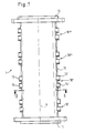
- a reactor 1 of a device for sterilizing water which has a tubular housing 10, at the axial ends of an inlet flange 11 and an outlet flange 12 are arranged.
- the housing 10 has four consecutive substantially identical housing sections 10 ', 10 ", 10"', 10 "" over its axial extent. Each of these housing sections is provided at diametrically opposite locations with a first 13 and a second 13 'contact bushing for the anode connection and a first 14 and a second (14') contact bushing for the cathode connection.
- the contact bushings 13, 13 ', 14, 14' are designed as radially extending tube sections which penetrate the wall of the housing 10 and are connected in a sealing and pressure-tight manner on their outer circumference to the wall of the housing 10.
- the first contact bushings 13, 14 and the second contact bushings 13 ', 14' are each arranged side by side in the direction of the axis X of the tubular housing 10.
- a housing 10 Since each housing section is provided with contact bushings 13, 13 ', 14, 14', a housing 10 has a plurality of diametrically opposite first and second contact bushing pairs corresponding to the number of housing sections, as can be seen in FIG. 1.
- Fig. 2 shows a cross section through a reactor 1 along the line II - II in Fig. 1.
- the tubular cross section of the housing 10 with the two radially opposite first and second contact bushings 14, 14 'for the cathode connection can be clearly seen.
- a square frame 20 is used, which serves to hold the electrodes 3, 4 and preferably consists of food-safe PVC.
- the corners of the frame 20 are chamfered or rounded on the outer sides and the frame 20 is inserted into the housing 10 with a precise fit such that the chamfered or rounded corners abut the inside of the tubular housing 10.
- the upper edge and the lower edge of the frame run parallel to the axis 14 '' common to the contact bushings 14, 14 '.
- the frame 20 consists of two side frame walls 23, 23 ', each of the first and the second contact bushing for the anode connection and the cathode connection 13, 14; 13 ', 14' are located adjacent.
- the upper and lower walls of the frame 20 are formed by an upper comb plate 21 and a lower comb plate 21 '.
- the comb plates 21, 21 ' are provided on their surface facing the inside of the frame with grooves 24 arranged next to one another and running parallel to the axis X of the housing 10.
- a web 22 projecting into the interior of the frame is provided between the grooves 24.
- the grooves 24 serve to guide plate-shaped electrodes 3, 4 inserted into the frame 20, which extend parallel to the side walls 23, 23 'of the frame 20 and whose plate size is preferably approximately 200 mm ⁇ 100 mm. Although only 3 electrodes are shown by way of example in FIG. 2, each pair of grooves 24, 24 'serves to guide an electrode, with cathode 4 and anode 3 alternating and each defining a gap 25 between them which defines the width of the associated web 22 or 22 'and is preferably approximately 1.3 mm, the respective thickness of the anode and cathode being approximately 1 mm.
- the number of cathodes is one more than that of the anodes, so that a cathode rests on each side wall 23, 23 'without a gap being formed between this outermost cathode and the associated side wall 23, 23'.
- the space 26 between the outside of the frame 20 and the inside of the tubular housing 10 is sealed off from the interior of the frame and filled or foamed, for example.
- the seal with respect to the interior of the frame 20 can be made, for example, by circular segment-shaped covers fastened in the area of the inlet flange 11 on the end faces of the frame walls, which covers only the preferably square inner surface of the frame 20 as a passage cross section for the water flowing through the reactor.
- Each housing section 10 ′, 10 ′′, 10 ′′ ′′, 10 ′′ ′′ has an electrode module (2 ′, 2 ′, 2 ′′, 2 ′′) configured as described above and arranged in a frame 20.
- FIG. 4 shows the alternating arrangement of anodes 3 and cathodes 4 with the gaps 25 in between.
- Each anode 3 and each cathode 4 has two spaced-apart openings of different diameters.
- the smaller opening 33 or 43 is designed for the loose passage of a tie rod 34 for the anode or a tie rod 44 for the cathode.
- the larger opening 45 of the cathode 4 permits the passage of the tie rod 34 of the anode, a radial distance being provided between the tie rod 34 and the opening edge of the opening 45.
- the larger opening 35 of the anode 3 allows the passage of the tie rod 44 of the cathode 4 while maintaining a radial distance.
- the respective tie rod 34 or 44 can consist of electrically conductive or non-conductive material.
- FIG. 5 shows the section labeled V in FIG. 4.
- the tie rod 44 penetrates the smaller openings 43 ', 43' 'of the successive cathodes 4', 4 '', the distance between the respective openings 43 ', 43' 'and the outer circumference of the tie rod 44 being such that there is axial movement of the tie rod 44 is possible.
- a conductive spacer ring 46 made of a valve metal, preferably titanium, which rests with its end faces against the mutually facing surfaces of the successive cathodes 4', 4 ''.
- the inner diameter of the spacer ring 46 corresponds essentially to the bores 43 ', 43' ', so that the spacer ring 46 does not hinder an axial movement of the tie rod 44 either.
- an insulating intermediate ring 47 Arranged radially outside of the conductive spacer ring 46 is an insulating intermediate ring 47 which, with its inner circumference, surrounds the outer circumference of the spacer ring 46 and which is somewhat shorter in the axial direction than a conductive spacer ring or is elastic and with its end faces on the mutually facing surfaces of the successive cathodes 4, 4 'is applied.
- the outer circumference of the insulating intermediate ring 47 lies against the inner circumference of the larger opening 35 of the anode 3 'located between the cathodes 4', 4 ''.
- the tie rod 44 on the cathode side is provided at its ends with a threaded section 44 ′, 44 ′′ in each case.
- the anode-side tie rod 34 also has threaded sections 34 'and 34' 'at its ends.
- a contact pin 7 shown in more detail in FIG. 3 is screwed by means of an internal thread 70, which is provided in an axial bore 71 located at one end of the contact pin 7.
- the latter has an annular end face 72 which comes into contact with the outer surface of the outermost cathode 4 '''and presses it against the spacer ring 46' located on the other side of this cathode.
- the result is at the respective separation points between the tie rod end face 72, the cathode 4' '', the spacer ring 46 ', the cathode 4' ', the spacer ring 46, the cathode 4', etc. a very high surface pressure, which reduces the respective electrical contact resistance and thus allows high electrical currents to be conducted between the contact bolts and between the cathodes while minimizing resistance losses. In this way, resistance polarization is avoided at the contact surfaces and the associated corrosion is prevented.
- the anodes are electrically contacted with one another and with the associated contact pins (not shown) which are assigned to them.
- a contact bolt with its annular end face 72 first presses against the annular end face of a conductive spacer ring 36 then again on the adjacent anode 3 '' etc.
- the electrode module 2 shown in FIG. 4 is contacted with the external power supply or with the next module via the cathode-side contact bolts 7, 7 'and the anode-side contact bolts, not shown in FIG. 4.
- the contact bolts 7, 7 ' are sealingly led out of the housing 10 through the associated contact bushing 14 or 14' for the cathode.
- the anode-side contact bolts, not shown, are led out of the housing 10 through the contact bushings 13, 13 '.
- a contact pin 7 has two axially spaced circumferential grooves 73, 74, in each of which a sealing ring 75, 76 is inserted, each with the groove 73 and 74 and the inner circumference of the contact bushing 14, 14 '; 13, 13 'cooperates in a sealing manner.
- the contact pin 7 is provided with an axial pin 78 to form a contact surface 77, which is designed to receive a known cable lug.
- the axial pin 78 is followed by an axially directed threaded bolt 79 which is designed to screw on a suitable nut which presses the cable lug (not shown) of a connecting cable against the contact surface 77.
- FIG. 6 The structure of an anode is shown in FIG. 6.
- a first layer 31 of a suitable conductive material is applied to an anode core 30, which is preferably made of a valve metal such as titanium, to which in turn a second layer 32 of another suitable conductive material is applied.
- the second layer can in turn be followed by a first layer and this in turn by a second layer, etc.
- One of the two layers 31, 32 consists of a titanium mixed oxide and the other of the two layers is made of a platinum-iridium alloy. It does not matter which of the two layers is applied first to the anode core 30; however, it is essential that the layers 31, 32 alternate with one another.
- a coating can be dispensed with in order to improve the electrical conductivity between the anodes and the adjacent spacer rings, so that the spacer rings directly on core 30 of the anode consisting of the valve metal.
- the cathode is preferably made of a (rustproof) stainless steel, such as V2A steel.
- the object of the invention is aimed at the overvoltage of the oxygen deposition over the overvoltage of the chlorine deposition through a particularly smooth surface and through the selection of the successive anode layers described above as high as possible.
- Fig. 7 shows the potential behavior of the selected anode with the structure described above (shown in broken lines).
- the ordinate shows the anode potential in volts and the abscissa shows the current density in mA / cm 2 .
- the solid curve indicates the chlorine evolution and the dash-dotted line represents the oxygen evolution.
- the partial oxygen stron density i 02 is lower than the partial chlorine stron density i Cl2 . It is thereby achieved that on the one hand the development of oxygen is reduced to a desired minimum even at high current densities and, on the other hand, due to the high potential, oxygen compounds with a high oxidation potential (peroxo compounds and singlet oxygen) are predominantly formed in addition to OH radicals.
- FIG. 8 shows the structure of a controlled device for the disinfection of water with a reactor 1, through which the water flows in FIG. 8 from bottom to top in the direction of the arrows W, W '.
- the reactor consists of four electrode modules 2 ', 2 ", 2"",2""' arranged one behind the other in the flow direction.
- the cathode side of the first electrode module 2 ' is the negative output pole of a power supply device 5 connected via a minus supply line 67.
- the minus supply line 67 is branched, each branch being connected to one of the contact bolts 7, 7' shown in Fig. 4.
- the two anode-side contact bolts of the electrode module 2 are connected to the cathode-side contact bolts of the following electrode module 2 ′′ via bridge lines 68, 69.
- the electrode modules 2 ′′ and 2 ′′ ′′ and 2 ′′ ′′ and 2 ′′ ′′ are electrically connected to one another
- the anode-side contact bolts of the last electrode module 2 '''' are the two branches of a plus supply line 66, which is also branched out connected, which connects the anodes of the last electrode module 2 '''' to the positive connection pole of the power supply device 5.
- the measuring point of a measuring device 60 is arranged, by means of which the oxidants contained in the water, which can be determined as chlorine equivalents, can be measured.
- the measuring device 60 is connected via a measuring line 63 to a computer unit 62, via which measurement data are supplied from the measuring device 60 to the computer unit 62.
- the computer unit 62 determines from the measurement data supplied to it the concentration of the oxidants contained in the water of the outlet channel, which can be determined as chlorine equivalents. From this concentration, the computer unit determines the partial chloride current density using data supplied by the power supply device 5, which represent the electrical current flowing through the reactor, and knowledge of the total active electrode area in the reactor. A value proportional to this partial chloride current density is passed on to a control unit 61 via a data line 64. This determined value for the partial chloride current density is compared in the control unit 61 with the corresponding value of a partial chloride current density of a predetermined concentration of free oxidants, which can be determined as chlorine equivalents. The difference value resulting from this comparison is converted by the control unit into a control signal which is fed to the power supply device 5 via a control line 65.
- the power supply device 5 obtains its electrical energy from an alternating current source indicated by a wavy line. It converts this alternating current into direct current um, the DC voltage at the + and - designated DC connections of the power supply device 5 for the supply lines 66 and 67 of the reactor 1 being set in accordance with the electrical current flow specified by the control unit 61.
- a preferred DC voltage is in the range of 6 to 7 volts per electrode module, so that due to the series connection of the electrode modules in the example of FIG. 8, approximately 24 to 28 volts are present at the outputs of the power supply device 5.
- the regulation described above allows the entire device to be set to a predetermined concentration of free oxidants, which can be determined as chlorine equivalents, in accordance with the microbial load on the water. This setting must be carried out when setting up the device and can be repeated for checking at greater intervals. Changes that occur in the meantime to the boundary conditions relevant to the electrochemical process, such as, for example, changes in the conductivity of the water or changes in the effectiveness of the individual electrode modules, are detected by the measuring and control device 6 due to the change in the concentration of oxidants in the outlet channel that can be determined as chlorine equivalents. The measuring and control device 6 then regulates the electrical current flowing through the reactor in the sense of a correction of the partial chloride current density.
- the anode consists of a valve metal core with a homogeneous electrocatalytically active coating, which is composed predominantly of a compound of titanium and at least one platinum metal in oxidic and / or non-oxidic form.
Abstract
Description
Die Erfindung betrifft eine Vorrichtung zur Entkeimung von Wasser mittels anodischer Oxidation mit einem zumindest je eine Anode und eine Kathode aufweisenden, von Wasser durchströmbaren Reaktor sowie einer mit der Anode und der Kathode verbundenen elektrischen Stromversorgungseinrichtung, wobei zwischen einander zugewandten Flächen von Anode und Kathode ein Spalt mit gleichbleibender Spaltbreite vorgesehen ist, wobei die Anode aus einem Ventilmetallkern mit einer homogenen elektrokatalytisch aktiven Beschichtung besteht, die sich überwiegend aus einer Verbindung von Titan und zumindest einem Platinmetall zusammensetzt.The invention relates to a device for disinfecting water by means of anodic oxidation with a water-flowable reactor having at least one anode and one cathode each, and an electrical power supply device connected to the anode and the cathode, with a gap between facing surfaces of the anode and cathode is provided with a constant gap width, wherein the anode consists of a valve metal core with a homogeneous electrocatalytically active coating, which is composed predominantly of a compound of titanium and at least one platinum metal.
Eine derartige Vorrichtung ist aus der US-A-4,202,738 bekannt. In diesem bekannten Reaktor sind eine Mehrzahl von bipolaren Elektrodenplatten angeordnet, die von aufgesalzenem Wasser durchströmt werden.Such a device is known from US-A-4,202,738. In this known reactor, a plurality of bipolar electrode plates are arranged, through which salted water flows.
Eine künstliche Aufsalzung von Süßwasser mittels Halogensalzen bzw. ein Mindestgehalt an Halogensalzen im Wasser ist bei dieser bekannten Vorrichtung erforderlich, um eine zur Entkeimung des Wassers ausreichende Menge Chlor elektrolytisch zu erzeugen.An artificial salting of fresh water by means of halogen salts or a minimum content of halogen salts in the water is required in this known device in order to Disinfection of the water to generate sufficient amount of chlorine electrolytically.
Es ist daher die Aufgabe der vorliegenden Erfindung, eine gattungsgemäße Vorrichtung zur Entkeimung von Wasser mittels anodischer Oxidation sowie ein Verfahren zur Entkeimung von Wasser anzugeben, die es gestatten, eine biozide Behandlung von Wasser auch bei niedrigen Chloridkontentrationen des Wassers durchzuführen.It is therefore the object of the present invention to provide a generic device for disinfecting water by means of anodic oxidation and a method for disinfecting water which make it possible to carry out a biocidal treatment of water even at low chloride concentrations in the water.
Der die Vorrichtung betreffende Teil dieser Aufgabe wird gemäß dem kennzeichnenden Teil des Patentanspruchs 1 dadurch gelöst, daß mehrere Anoden und mehrere Kathoden in einem Elektrodenmodul für einen Reaktor angeordnet sind und daß ein Reaktor eine Mehrzahl von Elektrodenmodulen aufweist, daß die Elektrodenmodule untereinander als elektrische Serienschaltung verbunden sind und daß sowohl die Anoden als auch die Kathoden eines jeden Elektrodenmoduls jeweils untereinander elektrisch leitend in Paralellschaltung miteinander verbunden sind.The part of the object relating to the device is achieved according to the characterizing part of patent claim 1 in that several anodes and several cathodes are arranged in an electrode module for a reactor and that a reactor has a plurality of electrode modules, that the electrode modules are connected to one another as an electrical series circuit and that both the anodes and the cathodes of each electrode module are connected to each other in an electrically conductive manner in parallel.
Der modulare Aufbau der Vorrichtung erhöht auch die Wirtschaftlichkeit der Vorrichtung bei der Fertigung und bei der Wartung. Außerdem wird dadurch ermöglicht, daß eine Mehrzahl von Elektrodenmodulen untereinander als elektrische Serienschaltung verbunden sind. Auf diese Weise wird erreicht, daß unter Beibehaltung der jeweils zwischen Anode und Kathode herrschenden vorgegebenen Spannung eine erhebliche Vergrößerung des aktiven Reaktorvolumens und der Anodenfläche möglich ist, ohne den insgesamt durch den Reaktor fließenden elektrischen Strom zu erhöhen, da aufgrund der Serienschaltung der Module die notwendige elektrische Leistungserhöhung über eine Erhöhung der am Reaktor insgesamt anliegenden Spannung erzielt wird.The modular structure of the device also increases the cost-effectiveness of the device during manufacture and maintenance. It also enables a plurality of electrode modules to be connected to one another as an electrical series circuit. In this way it is achieved that, while maintaining the predetermined voltage prevailing between the anode and cathode, a considerable increase in the active reactor volume and the anode area is possible without increasing the total electrical current flowing through the reactor, since due to the series connection of the modules the necessary electrical power increase is achieved by increasing the total voltage applied to the reactor.
Der das Verfahren betreffende Teil der Aufgabe wird durch das im Anspruch 13 angegebene Verfahren gelöst.The part of the task relating to the method is solved by the method specified in
Eine bevorzugte Weiterbildung der Vorrichtung kennzeichnet einen besonders geeigneten Anoden-Aufbau, wobei der aus Ventilmetall, wie bespielsweise Titan, Niob oder Tantal, bestehende Kern der Anode aufgrund der Eigenschaft eines Ventilmetalls, im Elektrolyten eine schützende, stabile Oxidschicht zu bilden, dafür sorgt, daß in Bereichen, in denen die Beschichtung des Anodenkerns Lücken aufweist, keine Korrosion des Anodenkerns auftritt. Die Wirksamkeit einer derartigen Anode wird weiter dadurch verbessert, daß eine Mehrzahl von Schichten-Paaren vorgesehen ist, die sich einander abwechselnd aufgetragen sind. Ein bevorzugtes Ventilmetall für den Anodenkern ist Titan.A preferred further development of the device features a particularly suitable anode structure, the core of the anode consisting of valve metal, such as titanium, niobium or tantalum, due to the property of a valve metal to form a protective, stable oxide layer in the electrolyte, ensures that in areas in which the coating of the anode core has gaps, none Corrosion of the anode core occurs. The effectiveness of such an anode is further improved by providing a plurality of pairs of layers which are applied alternately to one another. A preferred valve metal for the anode core is titanium.
Durch die besonders glatte Oberfläche der Anode nach Anspruch 5 wird - im Gegensatz zur üblichen Elektrolyse - die Langzeitkonstanz der Anodenaktivität erhöht, da die gesamte aktive Oberfläche der Anode aufgrund der geringen Rauhtiefe durch Adsorbatschichten nicht blockiert wird.In contrast to conventional electrolysis, the particularly smooth surface of the anode according to
Bevorzugte Ausbildungen zur Gewährleistung einer gewünschten laminaren Strömung sind nach Anspruch 6 die parallele Anordnung von Anode und Kathode, wobei Anode und Kathode bevorzugt von planparallelen Platten gebildet sind, sowie nach Anspruch 8 die konzentrische Anordnung von rohrförmigen Anoden und rohrförmigen Kathoden.Preferred configurations for ensuring a desired laminar flow are, according to
Die Kontaktierung der Elektroden gemäß den Ansprüchen 9, 10 und 11 verhindert aufgrund der hohen Flächenpressung zwischen den Grenzflächen von Elektroden und Abstandselementen weitgehend eine Widerstandspolarisation, so daß die elektrochemische Korrosion an den Grenzflächen nahezu vermieden wird. Diese Kontaktierung ist unter Wasser besonders sicher und wirksam und kann jederzeit wieder gelöst werden.The contacting of the electrodes according to
Sind gemäß Anspruch 12 in Strömungsrichtung hinter dem Reaktor eine Meßeinrichtung zur Bestimmung der Chloräquivalente der im Wasser befindlichen Oxidantien sowie eine dieses Meßsignal weiterverarbeitende Regeleinheit zur Regelung der Stromversorgungseinrichtung vorgesehen, so kann ein besonders wirksamer automatischer Betrieb der Vorrichtung erfolgen. Insbesondere ist eine derartige Vorrichtung geeignet, das Verfahren zur Entkeimung von Wasser mittels anodischer Oxidation nach Anspruch 15 durchzuführen, wobei durch die Bestimmung der Konzentration der Chloräquivalente der Oxidantien und den Vergleich dieser gemessenen Konzentration mit einem Sollwert, nämlich der Konzentration, die zur Abtötung der Keime notwendig ist, die elektrische Gesamtstromdichte verändert werden kann.According to
Aufgrund der laminaren Strömung zwischen den einander zugewandten Flächen von Anode und Kathode wird gewährleistet, daß auch bei nur geringer Konzentration von gelösten Chlorid; Ionen im Wasser diese mittels elektrostatischer Migration im homogenen Potentialfeld gleichmäßig zur Anodengrenzschicht transportiert werden, ohne dabei von turbulenten Strömungsvektoren in ihrer Migrationsbewegung gehindert zu werden. Gleichzeitig wird durch die erfindungsgemäße Wahl des Anodenwerkstoffs gewährleistet, daß die unerwünschte Erzeugung von molekularem Sauerstoff - und damit die unerwünschte Gasblasenbildung auf den Elektrodenoberflächen gegenüber der Erzeugung von Chlor, Chlorsauerstoffsäuren, deren Salzen und anderen Oxidantien, die als Chloräquivalente bestimmt werden können, (wie beispielsweise alle mit DPD (Diethyl-p-Phenylendiamin) nachweisbaren Oxidantien, überwiegend HOCl und OCl-) herabgesetzt ist.The laminar flow between the facing surfaces of the anode and cathode ensures that even with only a low concentration of dissolved chloride; Ions in water are transported evenly to the anode boundary layer by means of electrostatic migration in the homogeneous potential field, without being hindered in their migration movement by turbulent flow vectors. At the same time, the choice of anode material according to the invention ensures that the undesired generation of molecular oxygen - and thus the undesired formation of gas bubbles on the electrode surfaces compared to the production of chlorine, chlorine-oxygen acids, their salts and other oxidants, which can be determined as chlorine equivalents (such as all oxidants detectable with DPD (diethyl-p-phenylenediamine), predominantly HOCl and OCl-) are reduced.
Die Erfindung wird nachfolgend anhand eines Beispiels unter Bezugnahme auf die Zeichnung näher erläutert; in dieser zeigt:
- Fig. 1.
- eine Seitenansicht eines Reaktors der Vorrichtung nach der Erfindung,
- Fig. 2.
- einen Schnitt nach Linie II - II durch den Reaktor aus Fig. 1,
- Fig. 3.
- einen Kontaktbolzen,
- Fig. 4.
- einen Schnitt durch ein Elektrodenmodul entsprechend der Schnittrichtung IV - IV in Fig. 2,
- Fig. 5.
- einen Ausschnitt eines Elektrodenmoduls nach V in Fig. 4,
- Fig. 6.
- eine vergrößerte Darstellung des Anodenaufbaus,
- Fig. 7.
- das Potentialverhalten eines bevorzugten Anodenmaterials und
- Fig. 8.
- den schematischen Aufbau einer Vorrichtung der Erfindung mit vorgesehener Regelung.
- Fig. 1.
- a side view of a reactor of the device according to the invention,
- Fig. 2.
- 2 shows a section along line II-II through the reactor from FIG. 1,
- Fig. 3.
- a contact pin,
- Fig. 4.
- 3 shows a section through an electrode module in accordance with the cutting direction IV-IV in FIG. 2,
- Fig. 5.
- 4 shows a section of an electrode module according to V in FIG. 4,
- Fig. 6.
- an enlarged view of the anode structure,
- Fig. 7.
- the potential behavior of a preferred anode material and
- Fig. 8.
- the schematic structure of a device of the invention with proposed control.
In Fig. 1 ist ein Reaktor 1 einer Vorrichtung zur Entkeimung von Wasser dargestellt, der ein rohrförmiges Gehäuse 10 aufweist, an dessen axialen Enden ein Einlaßflansch 11 sowie ein Auslaßflansch 12 angeordnet sind.In Fig. 1, a reactor 1 of a device for sterilizing water is shown, which has a
Das Gehäuse 10 weist über seiner Axialerstreckung vier aufeinanderfolgende im wesentlichen identische Gehäuseabschnitte 10', 10", 10"', 10"" auf. Jeder dieser Gehäuseabschnitte ist an diametral gegenübergelegenen Orten mit einer ersten 13 sowie einer zweiten 13' Kontaktdurchführung für den Anodenanschluß und einer ersten 14 sowie einer zweiten (14') Kontaktdurchführung für den Kathodenanschluß versehen. Die Kontaktdurchführungen 13, 13', 14, 14' sind als sich radial erstreckende Rohrabschnitte ausgebildet, die die Wandung des Gehäuses 10 durchdringen und an ihrem Außenumfang mit der Wandung des Gehäuses 10 abdichtend und druckfest verbunden sind. Die ersten Kontaktdurchführungen 13, 14 bzw. die zweiten Kontaktdurchführungen 13', 14' sind jeweils in Richtung der Achse X des rohrförmigen Gehäuses 10 nebeneinander angeordnet.The
Da jeder Gehäuseabschnitt mit Kontaktdurchführungen 13, 13', 14, 14' versehen ist, besitzt ein Gehäuse 10 eine der Anzahl der Gehäuseabschnitte entsprechende Mehrzahl von einander diametral gegenüberliegenden ersten und zweiten Kontaktdurchführungs-Paaren, wie dies in Fig. 1 zu erkennen ist.Since each housing section is provided with
Fig. 2 stellt einen Querschnitt durch einen Reaktor 1 entlang der Linie II - II in Fig. 1 dar. Deutlich ist der rohrförmige Querschnitt des Gehäuses 10 mit den beiden radial gegenübergelegenen ersten und zweiten Kontaktdurchführungen 14, 14' für den Kathodenanschluß zu erkennen. In das rohrförmige Gehäuse 10 ist ein quadratischer Rahmen 20 eingesetzt, der zur Aufnahme der Elektroden 3, 4 dient und vorzusweise aus lebensmittelechtem PVC besteht. Die Ecken des Rahmens 20 sind an den Außenseiten abgeschrägt oder abgerundet und der Rahmen 20 ist in das Gehäuse 10 paßgenau derart eingesetzt, daß die abgeschrägten oder abgerundeten Ecken an der Innenseite des rohrförmigen Gehäuses 10 anliegen. Die Oberkante und die Unterkante des Rahmens verlaufen dabei parallel zu der den Kontaktdurchführungen 14, 14' gemeinsamen Achse 14''.Fig. 2 shows a cross section through a reactor 1 along the line II - II in Fig. 1. The tubular cross section of the
Der Rahmen 20 besteht aus zwei seitlichen Rahmenwänden 23, 23', die jeweils der ersten bzw. der zweiten Kontaktdurchführung für den Anodenanschluß und den Kathodenanschluß 13, 14; 13', 14' benachbart gelegen sind. Die obere und die untere Wand des Rahmens 20 werden von einer oberen Kammplatte 21 und einer unteren Kammplatte 21' gebildet. Die Kammplatten 21, 21' sind auf ihrer der Innenseite des Rahmens zugewandten Fläche mit nebeneinander angeordneten und parallel zur Achse X des Gehäuses 10 verlaufenden Nuten 24 versehen. Zwischen den Nuten 24 ist jeweils ein in den Rahmeninnenraum ragender Steg 22 vorgesehen.The
Die Nuten 24 dienen zur Führung von in den Rahmen 20 eingesetzten plattenförmigen Elektroden 3, 4, die sich parallel zu dem Seitenwänden 23, 23' des Rahmens 20 erstrecken und deren Plattengröße bevorzugt etwa 200 mm x 100 mm beträgt. Obwohl in Fig. 2 nur 3 Elektroden beispielhaft eingezeichnet sind, dient jedes Nutenpaar 24, 24' zur Führung einer Elektrode, wobei sich Kathode 4 und Anode 3 abwechseln und jeweils zwischen sich einen Spalt 25 bestimmen, der die Breite des zugehörigen Stegs 22 bzw. 22' aufweist und bevorzugt etwa 1,3 mm beträgt, wobei die jeweilige Dicke von Anode und Kathode bei etwa 1 mm liegt. Bei dieser Elektrodenanordnung ist die Anzahl der Kathoden um eins größer als die der Anoden, so daß an jeder Seitenwand 23, 23' eine Kathode anliegt, ohne daß dabei zwischen dieser äußersten Kathode und der zugehörigen Seitenwand 23, 23' ein Spalt gebildet ist.The
Der Raum 26 zwischen der Außenseite des Rahmens 20 und der Innenseite des rohrförmigen Gehäuses 10 ist gegenüber dem Innenraum des Rahmens abgedichtet und beispielsweise gefüllt oder ausgeschäumt. Die Abdichtung gegenüber dem Innenraum des Rahmens 20 kann beispielsweise durch im Bereich des Einlaßflansches 11 auf den Stirnseiten der Rahmenwände befestigte kreissegmentförmige Abdeckungen erfolgen, die als Durchtrittsquerschnitt für das den Reaktor durchfließende Wasser nur die vorzugsweise quadratische Innenfläche des Rahmens 20 freilassen.The
Jeder Gehäuseabschnitt 10', 10", 10''', 10"" weist ein wie vorgehend beschrieben ausgestaltetes und in einem Rahmen 20 angeordnetes Elektrodenmodul (2', 2', 2", 2") auf.Each
Einen Schnitt entlang der Linie IV - IV in Fig. 2 zeigt Fig. 4. Dabei sind das Gehäuse 10 sowie eine Kontaktdurchführung 14 nur ausschnittweise dargestellt. Fig. 4 zeigt die abwechselnde Anordnung von Anoden 3 und Kathoden 4 mit den dazwischenliegenden Spalten 25. Jede Anode 3 und jede Kathode 4 weist zwei voneinander beabstandete Öffnungen unterschiedlichen Durchmessers auf. Die kleinere öffnung 33 bzw. 43 ist dabei zum lockeren Durchtritt eines Zugankers 34 für die Anode bzw. eines Zugankers 44 für die Kathode ausgebildet. Die größere Öffnung 45 der Kathode 4 läßt den Durchtritt des Zugankers 34 der Anode zu, wobei zwischen dem Zuganker 34 und dem Öffnungsrand der Öffnung 45 ein radialer Abstand vorgesehen ist. Ebenso läßt die größere Öffnung 35 der Anode 3 den Durchtritt des Zugankers 44 der Kathode 4 unter Einhaltung eines radialen Abstands zu. Der jeweilige Zuganker 34 bzw. 44 kann dabei aus elektrisch leitendem oder nicht leitendem Material bestehen.A section along the line IV-IV in FIG. 2 is shown in FIG. 4. The
Die Kontaktierung der Elektroden untereinander sei am Beispiel der Kathoden 4 anhand der Fig. 5 näher erläutert. Fig. 5 zeigt den mit V in Fig. 4 bezeichneten Ausschnitt.The contacting of the electrodes with one another is explained in more detail using the example of the
Der Zuganker 44 durchdringt die kleineren Öffnungen 43', 43'' der aufeinander folgenden Kathoden 4', 4'', wobei zwischen der jeweiligen Öffnung 43', 43'' und dem Außenumfang des Zugankers 44 soviel Abstand bleibt, daß eine Axialbewegung des Zugankers 44 möglich ist. Zwischen den aufeinander folgenden Kathoden 4', 4'' ist ein aus einem Ventilmetall, vorzugsweise Titan bestehender leitender Abstandsring 46 vorgesehen, der mit seinen Stirnflächen gegen die einander zugewandten Flächen der aufeinander folgenden Kathoden 4', 4'' anliegt. Der Innendurchmesser des Abstandsrings 46 entspricht dabei im wesentlichen den Bohrungen 43', 43'', so daß auch der Abstandsring 46 eine Axialbewegung des Zugankers 44 nicht behindert. Radial außerhalb des leitenden Abstandsrings 46 ist ein isolierender Zwischenring 47 angeordnet, der mit seinem Innenumfang den Außenumfang des Abstandsrings 46 umgibt und der in Axialrichtung etwas kürzer ist als ein leitender Abstandsring oder elastisch ist und mit seinen Stirnseiten an den einander zugewandten Flächen der aufeinander folgenden Kathoden 4, 4' anliegt. Der Außenumfang des isolierenden Zwischenrings 47 liegt dabei am Innenumfang der größeren Öffnung 35 der zwischen den Kathoden 4', 4'' gelegenen Anode 3' an.The
Der kathodenseitige Zuganker 44 ist an seinen Enden mit jeweils einem Gewindeabschnitt 44', 44'' versehen. Auch der anodenseitige Zuganker 34 besitzt an seinen Enden Gewindeabschnitte 34' und 34''.The
Die Kontaktierung der in Fig. 5 dargestellten Kathoden untereinander erfolgt auf die nachfolgend beschriebene Weise. Auf jedes Gewindeende 44', 44'' des kathodenseitigen Zugankers 44 wird ein in Fig. 3 näher gezeigter Kontaktbolzen 7 mittels eines Innengewindes 70, das in einer an einem Ende des Kontaktbolzens 7 gelegenen axialen Bohrung 71 vorgesehen ist, geschraubt. An dem mit dem Innengewinde 70 versehenen Ende des Kontaktbolzens 7 weist dieser eine ringförmige Stirnfläche 72 auf, die in Kontakt mit der Außenfläche der äußersten Kathode 4''' gerät und diese gegen den auf der anderen Seite dieser Kathode gelegenen Abstandsring 46' drückt. Dieser drückt wiederum gegen die nachfolgende Kathode 4', welche ihrerseits wiederum gegen den nachfolgenden Abstandsring 46 drückt usw.. Der auf das am anderen Ende des Zugankers 44 liegende Gewinde 44' geschraubte Kontaktbolzen 7' drückt dabei auf dieselbe Weise gegen die ihm zunächst gelegene Kathode.The contacting of the cathodes shown in FIG. 5 takes place in the manner described below. On each thread end 44 ', 44''of the tie rod on the
Werden nun die Kontaktbolzen 7, 7' gegeneinander verspannt, so entsteht an den jeweiligen Trennstellen zwischen der Zugankerstirnseite 72, der Kathode 4''', dem Abstandsring 46', der Kathode 4'', dem Abstandsring 46, der Kathode 4' usw. eine sehr hohe Flächenpressung, die den jeweiligen elektrischen Übergangswiderstand herabsetzt und so die Leitung hoher elektrischer Ströme zwischen den Kontaktbolzen und zwischen den Kathoden bei Minimierung von Widerstandsverlusten zuläßt. Auf diese Weise wird an den Berührungsflächen eine Widerstandspolarisation vermieden und damit einhergehende Korrosion verhindert.If the
Auf analoge Weise werden die Anoden untereinander und mit den ihnen zugeordneten - nicht gezeigten - Kontaktbolzen elektrisch kontaktiert. Da jedoch den Seitenwänden 23, 23' des Rahmens 20 benachbart zuerst immer eine Kathode gelegen ist, drückt im Bereich der Anodenkontaktierung (in Fig. 4 oben) ein Kontaktbolzen mit seiner ringförmigen Stirnfläche 72 zunächst gegen die ringförmige Stirnfläche eines leitenden Abstandsrings 36. Dieser drückt dann wiederum auf die ihm benachbarte Anode 3'' usw.. Die Kontaktierung des in Fig. 4 gezeigten Elektrodenmoduls 2 mit der externen Stromversorgung bzw. mit dem nächstfolgenden Modul erfolgt über die kathodenseitigen Kontaktbolzen 7, 7' sowie die in Fig. 4 nicht gezeigten anodenseitigen Kontaktbolzen.In an analogous manner, the anodes are electrically contacted with one another and with the associated contact pins (not shown) which are assigned to them. However, since there is always a cathode adjacent to the
Die Kontaktbolzen 7, 7' sind abdichtend durch die zugehörige Kontaktdurchführung 14 bzw. 14' für die Kathode aus dem Gehäuse 10 herausgeführt. Auf analoge Weise sind die nicht gezeigten anodenseitigen Kontaktbolzen durch die Kontaktdurchführungen 13, 13' aus dem Gehäuse 10 herausgeführt.The
Zur Abdichtung weist ein Kontaktbolzen 7 zwei axial voneinander beabstandete Umfangsnuten 73, 74 auf, in die jeweils ein Dichtungsring 75, 76 eingesetzt ist, der jeweils mit der Nut 73 bzw. 74 und dem Innenumfang der Kontaktdurchführung 14, 14'; 13, 13' abdichtend zusammenwirkt.For sealing, a
An seinem von der axialen Bohrung 71 abgewandten Ende ist der Kontaktbolzen 7 unter Ausbildung einer Kontaktfläche 77 mit einem Axialzapfen 78 versehen, welcher zur Aufnahme eines bekannten Kabelschuhs ausgebildet ist. An den Axialzapfen 78 schließt sich ein axial gerichteter Gewindebolzen 79 an, der zum Aufschrauben einer geeigneten Mutter ausgebildet ist, die den nicht gezeigten Kabelschuh eines Anschlußkabels gegen die Kontaktfläche 77 preßt.At its end facing away from the
Den Aufbau einer Anode zeigt Fig. 6. Auf einen vorzugsweise aus einem Ventilmetall wie Titan bestehenden Anodenkern 30 ist eine erste Schicht 31 eines geeigneten leitenden Materials aufgebracht, auf die wiederum eine zweite Schicht 32 eines anderen geeigneten leitenden Materials aufgebracht ist. Es kann auf die zweite Schicht wiederum eine erste Schicht und auf diese wiederum eine zweite Schicht usw. folgen. Eine der beiden Schichten 31, 32 besteht aus einem Titanmischoxid und die andere der beiden Schichten besteht aus einer Platin-Iridium-Legierung. Es spielt dabei keine wesentliche Rolle, welche der beiden Schichten zuerst auf den Anodenkern 30 aufgetragen ist; wesentlich ist aber, daß die Schichten 31, 32 einander abwechseln. Im Bereich der Anodenkontaktierung, d. h. in der die kleinere Öffnung 33 umgebenden Ringfläche, welche mit den anliegenden Abstandsringen 36 in Kontakt ist, kann zur Verbesserung der elektrischen Leitfähigkeit zwischen den Anoden und den angrenzenden Abstandsringen auf eine Beschichtung verzichtet werden, so daß die Abstandsringe direkt am aus dem Ventilmetall bestehenden Kern 30 der Anode anliegen. Die Kathode besteht bevorzugt aus einem (nicht rostenden) Edelstahl, wie beispielsweise V2A-Stahl.The structure of an anode is shown in FIG. 6. A
Entgegen der üblichen Zielvorstellung in der Elektrosynthese, durch hohe Oberflächenrauhigkeit die Anodenüberspannung einer bestimmten Umsetzung herabzusetzen, wird beim Gegenstand der Erfindung angestrebt, durch eine besonders glatte Oberfläche und durch die vorbeschriebene Auswahl der aufeinander folgenden Anoden-Schichten die Überspannung der Sauerstoffabscheidung gegenüber der Überspannung der Chlorabscheidung möglichst hochzusetzen.Contrary to the usual goal in electrosynthesis, to reduce the anode overvoltage of a certain implementation due to high surface roughness, the object of the invention is aimed at the overvoltage of the oxygen deposition over the overvoltage of the chlorine deposition through a particularly smooth surface and through the selection of the successive anode layers described above as high as possible.
Fig. 7 zeigt das Potentialverhalten der ausgewählten Anode mit dem vorstehend beschriebenen Aufbau (gestrichelt gezeichnet). Auf der Ordinate ist dabei das Anodenpotential in Volt und auf der Abszisse ist die Stromdichte in mA/cm2 angegeben. Die durchgezogene Kurve gibt die Chlorentwicklung an und die strichpunktierte Linie steht für die Sauerstoffentwicklung. Im gesamten Bereich oberhalb des Schnittpunktes der beiden Kurven ist die Sauerstoffteilstrondichte i02 geringer als die Chlorteilstrondichte iCl2. Dadurch wird erreicht, daß einerseits die Sauerstoffentwicklung auch bei hohen Stromdichten bis auf ein erwünschtes Mindestmaß reduziert wird und andererseits aufgrund des hohen Potentials überwiegend neben OH-Radikal auch Sauerstoffverbindungen mit hohem Oxidationspotential (Peroxo-Verbindungen sowie Singulett-Sauerstoff) entstehen.Fig. 7 shows the potential behavior of the selected anode with the structure described above (shown in broken lines). The ordinate shows the anode potential in volts and the abscissa shows the current density in mA / cm 2 . The solid curve indicates the chlorine evolution and the dash-dotted line represents the oxygen evolution. In the entire area above the intersection of the two curves, the partial oxygen stron density i 02 is lower than the partial chlorine stron density i Cl2 . It is thereby achieved that on the one hand the development of oxygen is reduced to a desired minimum even at high current densities and, on the other hand, due to the high potential, oxygen compounds with a high oxidation potential (peroxo compounds and singlet oxygen) are predominantly formed in addition to OH radicals.
Durch den vorbeschriebenen Aufbau der Anode wird auch bei niedrigen Chloridkonzentrationen (unter 10 mg/l), wie sie im Süßwasser auftreten können, gewährleistet, daß bei noch verhältnismäßig geringen elektrischen Strömen eine für eine zuverlässige Entkeimung des Wassers ausreichende Menge an Oxidantien erzeugt wird, die als Chloräquivalente bestimmt werden können.Due to the above-described structure of the anode, even at low chloride concentrations (below 10 mg / l), as can occur in fresh water, it is ensured that at relatively low electrical currents a sufficient amount of oxidants is generated for a reliable disinfection of the water can be determined as chlorine equivalents.
Fig. 8 zeigt den Aufbau einer geregelten Vorrichtung zur Entkeimung von Wasser mit einem Reaktor 1, welcher in Fig. 8 von unten nach oben in Richtung der Pfeile W, W' vom Wasser durchströmt wird. Der Reaktor besteht entsprechend der Darstellung in Fig. 1 aus vier in Durchflußrichtung hintereinander angeordneten Elektrodenmodulen 2', 2", 2''', 2''''. Dabei ist die Kathodenseite des ersten Elektrodenmoduls 2' mit dem negativen Ausgangspol einer Stromversorgungseinrichtung 5 über eine Minus-Versorgungsleitgung 67 verbunden. Zur gleichmäßigen Stromeinleitung in das Elektrodenmodul 2' ist die Minus-Versorgungsleitung 67 aufgezweigt, wobei jeder Zweig an einen der in Fig. 4 gezeigten Kontaktbolzen 7, 7' angeschlossen ist. Die beiden anodenseitigen Kontaktbolzen des Elektrodenmoduls 2' sind über Brückenleitungen 68, 69 mit den kathodenseitigen Kontaktbolzen des folgenden Elektrodenmoduls 2'' verbunden. Auf die gleiche Weise sind die Elektrodenmodule 2'' und 2''' sowie 2''' und 2'''' miteinander elektrisch verbunden. An die anodenseitigen Kontaktbolzen des letzten Elektrodenmoduls 2'''' sind die beiden Zweige einer ebenfalls aufgezweigten Plus-Versorgungsleitung 66 angeschlossen, welche die Anoden des letzten Elektrodenmoduls 2'''' mit dem positiven Anschlußpol der Stromversorgungseinrichtung 5 verbindet.FIG. 8 shows the structure of a controlled device for the disinfection of water with a reactor 1, through which the water flows in FIG. 8 from bottom to top in the direction of the arrows W, W '. 1, the reactor consists of four
Im stromabwärts des Reaktors gelegenen Auslaßkanal 15 ist die Meßstelle einer Meßeinrichtung 60 angeordnet, mittels derer die im Wasser enthaltenen Oxidantien, die als Chloräquivalente bestimmt werden können, gemessen werden können. Die Meßeinrichtung 60 ist über eine Meßleitung 63 mit einer Rechnereinheit 62 verbunden, über die Meßdaten von der Meßeinrichtung 60 an die Rechnereinheit 62 geliefert werden.In the
Die Rechnereinheit 62 ermittelt aus den ihr zugeführten Meßdaten die Konzentration der im Wasser des Auslaßkanals enthaltenen Oxidantien, die als Chloräquivalente bestimmt werden können. Aus dieser Konzentration ermittelt die Rechnereinheit unter Verwendung von ihr von der Stromversorgungseinrichtung 5 zugeführten Daten, die den durch den Reaktor fließenden elektrischen Strom repräsentieren, und unter Kenntnis der gesamten aktiven Elektrodenfläche im Reaktor die Chloridteilstromdichte. Ein dieser Chloridteilstromdichte proportionaler Wert wird über eine Datenleitung 64 an eine Regeleinheit 61 weitergegeben. In der Regeleinheit 61 wird dieser ermittelte Wert für die Chloridteilstromdichte mit dem entsprechenden Wert einer Chloridteilstromdichte einer vorgegebenen Konzentration an freien Oxidantien, die als Chloräquivalente bestimmt werden können, verglichen. Der aus diesem Vergleich resultierende Differenzwert wird von der Regeleinheit in ein Steuersignal umgewandelt, welches über eine Steuerleitung 65 der Stromversorgungseinrichtung 5 zugeführt wird.The
Die Stromversorgungseinrichtung 5 bezieht ihre elektrische Energie von einer durch eine Wellenlinie angedeuteten Wechselstromquelle. Sie wandelt diesen Wechselstrom in Gleichstrom um, wobei die an den mit + und - bezeichneten Gleichstromanschlüssen der Stromversorgungseinrichtung 5 für die Versorgungsleitungen 66 und 67 des Reaktors 1 liegende Gleichspannung entsprechend dem von der Regeleinheit 61 vorgegebenen elektrischen Stromfluß eingestellt wird. Eine bevorzugte Gleichspannung liegt im Bereich von 6 bis 7 Volt pro Elektrodenmodul, so daß aufgrund der Serienschaltung der elektrodenmodule im Beispiel der Fig. 8 etwa 24 bis 28 Volt an den Ausgängen der Stromversorgungseinrichtung 5 anliegen.The
Die vorbeschriebene Regelung gestattet es, die gesamte Vorrichtung entsprechend der mikrobiellen Belastung des Wassers auf eine vorgegebene Konzentration an freien Oxidantien, die als Chloräquivalente bestimmt werden können, einzustellen. Diese Einstellung muß bei der Einrichtung der Vorrichtung durchgeführt werden und kann zur Kontrolle in größeren Zeitabständen wiederholt werden. Zwischenzeitlich auftretende Änderungen der für den elektrochemischen Prozeß maßgeblichen Randbedingungen, wie beispielsweise Änderungen der Leitfähigkeit des Wassers oder Änderungen der Wirksamkeit der einzelnen Elektrodenmodule werden aufgrund der dadurch auftretenden veränderten Konzentration von als Chloräquivalente bestimmbaren Oxidantien im Auslaßkanal von der Meß- und Regelungseinrichtung 6 erfaßt. Daraufhin wird von der Meß- und Regelungseinrichtung 6 der durch den Reaktor fließende elektrische Strom im Sinne einer Korrektur der Chloridteilstromdichte geregelt.The regulation described above allows the entire device to be set to a predetermined concentration of free oxidants, which can be determined as chlorine equivalents, in accordance with the microbial load on the water. This setting must be carried out when setting up the device and can be repeated for checking at greater intervals. Changes that occur in the meantime to the boundary conditions relevant to the electrochemical process, such as, for example, changes in the conductivity of the water or changes in the effectiveness of the individual electrode modules, are detected by the measuring and
Es hat sich als vorteilhaft insbesondere bezüglich der Lebensdauer der Anoden erwiesen, wenn die Anode aus einem Ventilmetallkern mit einer homogenen elektrokatalytisch aktiven Beschichtung besteht, die sich überwiegend aus einer Verbindung von Titan und zumindest einem Platinmetall in oxidischer und/oder nicht oxidischer Form zusammensetzt.It has proven to be particularly advantageous with regard to the service life of the anodes if the anode consists of a valve metal core with a homogeneous electrocatalytically active coating, which is composed predominantly of a compound of titanium and at least one platinum metal in oxidic and / or non-oxidic form.
Claims (15)
- Apparatus for sterilizing water by anodic oxidation, comprising:- a reactor which has at least one anode and one cathode and through which water can flow and- an electric current supply means connected to the anode and cathode,- wherein a gap of constant width is provided between surfaces of the anode and cathode facing towards each other, and- wherein the anode (3) comprises a valve metal core (30) with a homogeneous, electro-catalytically active coating (31,32), made up preponderantly of a compound of titanium and at least one platinum metal in oxidic and/or non-oxidic form,characterised in that- a plurality of anodes (3, 3', 3'' ...) and a plurality of cathodes (4, 4', 4'' ...) are arranged in an electrode module (2) for a reactor (1), and that a reactor has a plurality of electrode modules (2', 2'', 2''', 2''''),- that the electrode modules (2', 2'', 2''', 2''') are interconnected in an electrical series arrangement and- that both the anodes (3, 3', 3'' . . .) and the cathodes (4, 4', 4'' ...) of each electrode module (2', 2'' , 2''', 2'''') are conductively interconnected among themselves in a parallel arrangement.
- Apparatus according to claim 1,
characterised in that
the coating of the valve metal core (30) of the anode (3) has at least two successive layers (31, 32), one of which comprises titanium mixed oxide and the other a platinumiridium alloy. - Apparatus according to claim 2,
characterised in that
a plurality of pairs of layers (31, 32) is provided, the layer of titanium mixed oxide and the layer of platinumiridium alloy being applied alternately. - Apparatus according to any of claims 1 to 3,
characterised in that
the core (30) of the anode (3) comprises titanium. - Apparatus according to any of claims 1 to 4,
characterised in that
the depth of the anode surface roughness is less than 1.0 µm. - Apparatus according to any of claims 1 to 5,
characterised in that
the anode (3) and cathode (4) are arranged in parallel. - Apparatus according to claim 6,
characterised in that
the anode (3) and cathode (4) are plates with parallel faces. - Apparatus according to any of claims 1 to 5,
characterised in that
the anode (3) and cathode (4) are in the form of concentrically arranged tubes. - Apparatus according to any of claims 1 to 8,
characterised in that
successive anodes (3', 3'') on the one hand and successive cathodes (4', 4'', 4''') on the other each have conductively interconnected spacer members (46, 46'), and that for the purpose of electrical contacting, the anodes (3', 3'') with their associated conductive spacer members and the cathodes (4', 4'', 4''') with their associated spacer members (46, 46') are pressed against each other at high pressure and to produce high surface pressure at the contact surfaces between the anodes and cathodes and the respective associated spacer members. - Apparatus according to claim 9,
characterised in thatthe anodes (3', 3'') on the one hand and the cathodes (4', 4'', 4''') on the other each have coaxial connecting holes (43', 43''; 33', 33'),that a cathode tensioning stay (44) is passed through the coaxial connecting holes (43', 43'') of the cathodes and is provided with threaded sections (44', 44'') at its ends,that the conductive cathode spacer members comprise spacer rings (46, 46'),that contact pins (7, 7') are screwed onto the threaded ends (44', 44'') of the cathode stay (44), end surfaces (72) of the pins which face towards each other pressing together the combined cathodes and spacer rings while applying tensile stress to the stay (44), andthat the anodes (3', 3'') are contacted in the same way by means of an anode stay (34) and associated contact pins. - Apparatus according to claim 10,
characterised in thatthe anodes (3', 3'') each have a hole of larger diameter coaxial with the cathode holes (43', 43'') and located in the region of the cathode tensioning stay (44), inside which hole the conductive cathode spacer ring (46, 46') is arranged in each case,that an insulating intermediate ring (47', 47'') is arranged between the periphery of the conductive cathode spacer ring (46, 46') and the anode (3', 3'') surrounding it, andthat the cathodes in the region of the anode stay (34) have the same structure and are insulated from the conductive anode spacer rings (36). - Apparatus according to any of claims 1 to 11,
characterised in thata measuring means (60) is provided downstream of the reactor (1) to determine oxidants in the water which can be determined as chlorine equivalents, andthat a control unit (61), which further processes a measurement signal received from the measuring means, is provided to control the current supply means (5). - A method of sterilizing water by anodic oxidation, using an apparatus according to claims 1 to 12,
characterised in that- water is supplied to a reactor comprising a plurality of electrode modules, each with at least one anode and one cathode,- that the water is successively passed through the respective electrode modules, between the anodes and the cathodes thereof, and- that the water is discharged from the reactor, an electrical voltage being applied between the respective anode and the respective cathode, thereby forming oxygen compounds and chlorine compounds which act as oxidants. - A method according to claim 13,
characterised in that
the water passes in a laminar flow between the respective anode and the respective cathode. - A method according to claim 13 or 14,
characterised in that- the concentration of free oxidants is measured downstream of the reactor (1),- that the concentration of free oxidants is determined as the concentration of chlorine equivalents,- that the concentration determined is compared to a desired value (the concentration necessary to kill the germs) and- that the electrical total current density is varied accordingly.
Applications Claiming Priority (3)
| Application Number | Priority Date | Filing Date | Title |
|---|---|---|---|
| DE4040694 | 1990-12-19 | ||
| DE4040694A DE4040694A1 (en) | 1990-12-19 | 1990-12-19 | DEVICE FOR DISinfecting WATER |
| PCT/EP1991/002459 WO1992011209A1 (en) | 1990-12-19 | 1991-12-19 | Water sterilising device |
Publications (2)
| Publication Number | Publication Date |
|---|---|
| EP0515628A1 EP0515628A1 (en) | 1992-12-02 |
| EP0515628B1 true EP0515628B1 (en) | 1996-09-25 |
Family
ID=6420748
Family Applications (1)
| Application Number | Title | Priority Date | Filing Date |
|---|---|---|---|
| EP92901093A Expired - Lifetime EP0515628B1 (en) | 1990-12-19 | 1991-12-19 | Device and method for sterilizing water |
Country Status (5)
| Country | Link |
|---|---|
| US (2) | US5439576A (en) |
| EP (1) | EP0515628B1 (en) |
| AT (1) | ATE143345T1 (en) |
| DE (2) | DE4040694A1 (en) |
| WO (1) | WO1992011209A1 (en) |
Families Citing this family (27)
| Publication number | Priority date | Publication date | Assignee | Title |
|---|---|---|---|---|
| EP0711730A4 (en) * | 1994-05-31 | 1996-12-27 | Toto Ltd | Electrolysis apparatus and electrolysis method for chloride ion-containing flowing water |
| US5534120A (en) * | 1995-07-03 | 1996-07-09 | Toto Ltd. | Membraneless water electrolyzer |
| US5876575A (en) * | 1995-09-05 | 1999-03-02 | Kump; Joseph A. | Method and apparatus for treatment of water |
| US5716503A (en) * | 1996-07-31 | 1998-02-10 | United Technologies Corporation | Center post electrochemical cell stack |
| ES2179722B1 (en) * | 1998-12-07 | 2004-02-01 | Integrated Pool Products Propr | WATER CHLORINE |
| US6315886B1 (en) | 1998-12-07 | 2001-11-13 | The Electrosynthesis Company, Inc. | Electrolytic apparatus and methods for purification of aqueous solutions |
| US7174678B2 (en) * | 1999-04-22 | 2007-02-13 | Hill-Rom Services, Inc. | Modular patient room |
| US6405491B1 (en) | 1999-04-22 | 2002-06-18 | Hill-Rom Services, Inc. | Modular patient room |
| DE10048299A1 (en) * | 2000-09-29 | 2002-05-29 | Aqua Butzke Werke Gmbh | Device for electrolytic water disinfection while avoiding cathodic hydrogen evolution |
| US7048842B2 (en) | 2001-06-22 | 2006-05-23 | The Procter & Gamble Company | Electrolysis cell for generating chlorine dioxide |
| US20030042134A1 (en) * | 2001-06-22 | 2003-03-06 | The Procter & Gamble Company | High efficiency electrolysis cell for generating oxidants in solutions |
| US6921743B2 (en) * | 2001-04-02 | 2005-07-26 | The Procter & Gamble Company | Automatic dishwashing compositions containing a halogen dioxide salt and methods for use with electrochemical cells and/or electrolytic devices |
| US7413637B2 (en) * | 2002-05-17 | 2008-08-19 | The Procter And Gamble Company | Self-contained, self-powered electrolytic devices for improved performance in automatic dishwashing |
| US20030213505A1 (en) * | 2002-05-17 | 2003-11-20 | Price Kenneth Nathan | Energy-efficient automatic dishwashing appliances |
| US20030213503A1 (en) * | 2002-05-17 | 2003-11-20 | The Procter & Gamble Company | Signal-based electrochemical methods for automatic dishwashing |
| FR2851560B1 (en) * | 2003-02-24 | 2006-08-11 | Europ De Traitement Des Eaux S | METHOD AND DEVICE FOR ELECTROCHEMICAL DISINFECTION OF WATER |
| DE102004005303A1 (en) * | 2004-01-29 | 2005-08-11 | Gao, Yuan, Dipl.-Ing. | Current supply in electrolytic water disinfection online monitoring with a two- electrode sensor has zero current flow at pole reversal |
| ITMI20041974A1 (en) * | 2004-10-18 | 2005-01-18 | De Nora Elettrodi Spa | IMPROVEMENT OF THE COD KILLING PROCESS FOR ELECTROCHEMICAL OXIDATION |
| EP1650329A3 (en) | 2004-10-21 | 2007-11-07 | Trust Sterile Services Limited | Apparatus and method for electrolytic cleaning |
| EP2331469A1 (en) * | 2008-09-30 | 2011-06-15 | Adept Water Technologies A/S | Device and process for removing microbial impurities in water based liquids as well as the use of the device |
| US8591707B2 (en) | 2011-05-03 | 2013-11-26 | Hydroripp, LLC | Hydrogen gas generator |
| US20130140245A1 (en) * | 2011-12-01 | 2013-06-06 | Neohydro Corp. | Direct contact cell |
| KR101310887B1 (en) * | 2013-03-19 | 2013-09-25 | 태랑엔지니어링(주) | Electric plate module of electrochemical treatment system in water treatment plant |
| WO2021089337A1 (en) * | 2019-11-08 | 2021-05-14 | Haldor Topsøe A/S | A cathode for water disinfection applications |
| WO2022170009A1 (en) | 2021-02-05 | 2022-08-11 | Xylem Water Solutions U.S.A., Inc. | System and method for recovering resources from wastewater streams |
| KR102358988B1 (en) * | 2021-04-30 | 2022-02-08 | 두산중공업 주식회사 | Rotary type capacitive de-onization device |
| EP4309811A1 (en) | 2022-07-18 | 2024-01-24 | Hammann GmbH | Method for the electromechanical removal of deposits in pipelines or apparatus |
Family Cites Families (12)
| Publication number | Priority date | Publication date | Assignee | Title |
|---|---|---|---|---|
| US3305472A (en) * | 1963-03-13 | 1967-02-21 | Dow Chemical Co | Purifying water with bromine |
| US4202738A (en) * | 1976-11-11 | 1980-05-13 | Diamond Shamrock Corporation | Electrolytic generation of halogen biocides |
| IT1094825B (en) * | 1978-05-11 | 1985-08-10 | Panclor Chemicals Ltd | PROCEDURE AND EQUIPMENT FOR THE HALOGENATION OF WATER |
| EP0140287B1 (en) * | 1983-11-02 | 1989-02-22 | Heraeus Elektroden GmbH | Polarity-reversable electrode |
| GB2176497A (en) * | 1985-05-31 | 1986-12-31 | Greaves And Sons Ltd Robert | Electrochlorination device |
| US4761208A (en) * | 1986-09-29 | 1988-08-02 | Los Alamos Technical Associates, Inc. | Electrolytic method and cell for sterilizing water |
| EP0322478A1 (en) * | 1987-12-30 | 1989-07-05 | Kay Wilms | Method and apparatus for the treatment of water by anodic oxidation, especially for the production of sterile drinking water |
| US5062940A (en) * | 1988-03-02 | 1991-11-05 | Water Regeneration Systems, Inc. | Electrolytic liquid purification apparatus |
| AU612513B2 (en) * | 1988-09-19 | 1991-07-11 | Poolrite Equipment Pty Limited | An in-pool convection saltwater chlorinator |
| FR2644155B1 (en) * | 1989-03-07 | 1991-05-24 | Levart Michel | ELECTROLYTIC WATER STERILIZATION APPARATUS |
| US5094734A (en) * | 1989-08-03 | 1992-03-10 | Torrado Santiago D | Water treatment unit |
| US5108563A (en) * | 1989-10-02 | 1992-04-28 | Environmental Systems (International) Limited | Process for treatment of water and apparatus therefor |
-
1990
- 1990-12-19 DE DE4040694A patent/DE4040694A1/en not_active Withdrawn
-
1991
- 1991-12-19 WO PCT/EP1991/002459 patent/WO1992011209A1/en active IP Right Grant
- 1991-12-19 EP EP92901093A patent/EP0515628B1/en not_active Expired - Lifetime
- 1991-12-19 US US07/920,510 patent/US5439576A/en not_active Expired - Lifetime
- 1991-12-19 DE DE59108232T patent/DE59108232D1/en not_active Expired - Lifetime
- 1991-12-19 AT AT92901093T patent/ATE143345T1/en not_active IP Right Cessation
-
1994
- 1994-07-07 US US08/271,877 patent/US5395492A/en not_active Expired - Lifetime
Also Published As
| Publication number | Publication date |
|---|---|
| US5439576A (en) | 1995-08-08 |
| WO1992011209A1 (en) | 1992-07-09 |
| DE59108232D1 (en) | 1996-10-31 |
| EP0515628A1 (en) | 1992-12-02 |
| US5395492A (en) | 1995-03-07 |
| DE4040694A1 (en) | 1992-06-25 |
| ATE143345T1 (en) | 1996-10-15 |
Similar Documents
| Publication | Publication Date | Title |
|---|---|---|
| EP0515628B1 (en) | Device and method for sterilizing water | |
| DE2749969C3 (en) | Electrolytic cell | |
| DE3030324C2 (en) | ||
| DE2948579C2 (en) | ||
| DE3640020C1 (en) | Electrolysis cell for the electrolytic deposition of metals | |
| DE2832664C2 (en) | Electrolysis cell for the electrolysis of sea water | |
| DE3043571A1 (en) | METHOD AND DEVICE FOR CARRYING OUT AN ELECTROLYTIC PROCESS | |
| DE102012214942A1 (en) | Continuous generator unit for electrolyzed oxidized / reduced water | |
| DE3028171C2 (en) | Filter press type electrolytic cell | |
| DE3324047A1 (en) | REPOLBABLE ELECTRODIALYSIS CELL AND ELECTRODES SUITABLE FOR THIS | |
| DE2645121C3 (en) | Electrolytic cell | |
| DE2023751A1 (en) | Device for electrolyzing salt water | |
| DE1949127C3 (en) | ||
| DE1949127B2 (en) | BIPOLAR ELECTROLYSIS CELL | |
| EP0332951A2 (en) | Method and apparatus for electrochemically disinfecting waters | |
| EP1036769A1 (en) | Apparatus for electrolytic treatment of water or aqueous solutions | |
| DE2119423A1 (en) | Electrolytic cell | |
| EP0029493B1 (en) | Vessel protected against internal corrosion | |
| DE2653536A1 (en) | BIPOLAR ELECTROLYSIS DEVICE WITH AN ELECTROLYTE BALANCING DEVICE | |
| EP0717791A1 (en) | Electrolytic cell with multiple partial electrodes and at least one antipolar counter-electrode | |
| EP0029494B1 (en) | Vessel protected against internal corrosion | |
| DE102019116469B4 (en) | Electrolytic cell, method for operating an electrolytic cell and use of an electrolytic cell | |
| DE2516246C2 (en) | Monopolar electrolytic cell | |
| DE4318533A1 (en) | Electrode cell anode projection electrically linked with main anode - reduces power requirement in production of chlorine@ from brine | |
| EP0543428A1 (en) | Electrolysis apparatus with protective electrodes |
Legal Events
| Date | Code | Title | Description |
|---|---|---|---|
| PUAI | Public reference made under article 153(3) epc to a published international application that has entered the european phase |
Free format text: ORIGINAL CODE: 0009012 |
|
| 17P | Request for examination filed |
Effective date: 19920916 |
|
| AK | Designated contracting states |
Kind code of ref document: A1 Designated state(s): AT DE FR GB |
|
| 17Q | First examination report despatched |
Effective date: 19930723 |
|
| GRAH | Despatch of communication of intention to grant a patent |
Free format text: ORIGINAL CODE: EPIDOS IGRA |
|
| GRAH | Despatch of communication of intention to grant a patent |
Free format text: ORIGINAL CODE: EPIDOS IGRA |
|
| GRAA | (expected) grant |
Free format text: ORIGINAL CODE: 0009210 |
|
| AK | Designated contracting states |
Kind code of ref document: B1 Designated state(s): AT DE FR GB |
|
| PG25 | Lapsed in a contracting state [announced via postgrant information from national office to epo] |
Ref country code: FR Effective date: 19960925 |
|
| REF | Corresponds to: |
Ref document number: 143345 Country of ref document: AT Date of ref document: 19961015 Kind code of ref document: T |
|
| REF | Corresponds to: |
Ref document number: 59108232 Country of ref document: DE Date of ref document: 19961031 |
|
| GBT | Gb: translation of ep patent filed (gb section 77(6)(a)/1977) |
Effective date: 19961216 |
|
| EN | Fr: translation not filed | ||
| PLBE | No opposition filed within time limit |
Free format text: ORIGINAL CODE: 0009261 |
|
| STAA | Information on the status of an ep patent application or granted ep patent |
Free format text: STATUS: NO OPPOSITION FILED WITHIN TIME LIMIT |
|
| 26N | No opposition filed | ||
| REG | Reference to a national code |
Ref country code: GB Ref legal event code: IF02 |
|
| PGFP | Annual fee paid to national office [announced via postgrant information from national office to epo] |
Ref country code: GB Payment date: 20041207 Year of fee payment: 14 |
|
| PG25 | Lapsed in a contracting state [announced via postgrant information from national office to epo] |
Ref country code: GB Free format text: LAPSE BECAUSE OF NON-PAYMENT OF DUE FEES Effective date: 20051219 |
|
| GBPC | Gb: european patent ceased through non-payment of renewal fee |
Effective date: 20051219 |
|
| PGFP | Annual fee paid to national office [announced via postgrant information from national office to epo] |
Ref country code: AT Payment date: 20070622 Year of fee payment: 16 |
|
| PG25 | Lapsed in a contracting state [announced via postgrant information from national office to epo] |
Ref country code: AT Free format text: LAPSE BECAUSE OF NON-PAYMENT OF DUE FEES Effective date: 20071219 |
|
| PGFP | Annual fee paid to national office [announced via postgrant information from national office to epo] |
Ref country code: DE Payment date: 20100127 Year of fee payment: 19 |
|
| REG | Reference to a national code |
Ref country code: DE Ref legal event code: R119 Ref document number: 59108232 Country of ref document: DE Effective date: 20110701 |
|
| PG25 | Lapsed in a contracting state [announced via postgrant information from national office to epo] |
Ref country code: DE Free format text: LAPSE BECAUSE OF NON-PAYMENT OF DUE FEES Effective date: 20110701 |