EP0515178A1 - Pneumatic tyre - Google Patents
Pneumatic tyre Download PDFInfo
- Publication number
- EP0515178A1 EP0515178A1 EP92304586A EP92304586A EP0515178A1 EP 0515178 A1 EP0515178 A1 EP 0515178A1 EP 92304586 A EP92304586 A EP 92304586A EP 92304586 A EP92304586 A EP 92304586A EP 0515178 A1 EP0515178 A1 EP 0515178A1
- Authority
- EP
- European Patent Office
- Prior art keywords
- belt
- steel
- monofilament
- waved
- cord
- Prior art date
- Legal status (The legal status is an assumption and is not a legal conclusion. Google has not performed a legal analysis and makes no representation as to the accuracy of the status listed.)
- Granted
Links
Images


Classifications
-
- D—TEXTILES; PAPER
- D07—ROPES; CABLES OTHER THAN ELECTRIC
- D07B—ROPES OR CABLES IN GENERAL
- D07B1/00—Constructional features of ropes or cables
- D07B1/06—Ropes or cables built-up from metal wires, e.g. of section wires around a hemp core
- D07B1/0606—Reinforcing cords for rubber or plastic articles
- D07B1/0646—Reinforcing cords for rubber or plastic articles comprising longitudinally preformed wires
-
- B—PERFORMING OPERATIONS; TRANSPORTING
- B60—VEHICLES IN GENERAL
- B60C—VEHICLE TYRES; TYRE INFLATION; TYRE CHANGING; CONNECTING VALVES TO INFLATABLE ELASTIC BODIES IN GENERAL; DEVICES OR ARRANGEMENTS RELATED TO TYRES
- B60C9/00—Reinforcements or ply arrangement of pneumatic tyres
- B60C9/0007—Reinforcements made of metallic elements, e.g. cords, yarns, filaments or fibres made from metal
-
- D—TEXTILES; PAPER
- D07—ROPES; CABLES OTHER THAN ELECTRIC
- D07B—ROPES OR CABLES IN GENERAL
- D07B2201/00—Ropes or cables
- D07B2201/20—Rope or cable components
- D07B2201/2001—Wires or filaments
- D07B2201/2007—Wires or filaments characterised by their longitudinal shape
- D07B2201/2008—Wires or filaments characterised by their longitudinal shape wavy or undulated
-
- D—TEXTILES; PAPER
- D07—ROPES; CABLES OTHER THAN ELECTRIC
- D07B—ROPES OR CABLES IN GENERAL
- D07B2201/00—Ropes or cables
- D07B2201/20—Rope or cable components
- D07B2201/2015—Strands
- D07B2201/2022—Strands coreless
-
- D—TEXTILES; PAPER
- D07—ROPES; CABLES OTHER THAN ELECTRIC
- D07B—ROPES OR CABLES IN GENERAL
- D07B2201/00—Ropes or cables
- D07B2201/20—Rope or cable components
- D07B2201/2015—Strands
- D07B2201/2024—Strands twisted
-
- D—TEXTILES; PAPER
- D07—ROPES; CABLES OTHER THAN ELECTRIC
- D07B—ROPES OR CABLES IN GENERAL
- D07B2201/00—Ropes or cables
- D07B2201/20—Rope or cable components
- D07B2201/2015—Strands
- D07B2201/2036—Strands characterised by the use of different wires or filaments
-
- D—TEXTILES; PAPER
- D07—ROPES; CABLES OTHER THAN ELECTRIC
- D07B—ROPES OR CABLES IN GENERAL
- D07B2201/00—Ropes or cables
- D07B2201/20—Rope or cable components
- D07B2201/2015—Strands
- D07B2201/2038—Strands characterised by the number of wires or filaments
- D07B2201/2039—Strands characterised by the number of wires or filaments three to eight wires or filaments respectively forming a single layer
-
- D—TEXTILES; PAPER
- D07—ROPES; CABLES OTHER THAN ELECTRIC
- D07B—ROPES OR CABLES IN GENERAL
- D07B2501/00—Application field
- D07B2501/20—Application field related to ropes or cables
- D07B2501/2046—Tire cords
Definitions
- the present invention relates to a belted pneumatic tyre, in which the belt durability and the steering stability are greatly improved.
- radial tyres are provided with tread reinforcing belts.
- tread reinforcing belts For such belts, a compact cord having a 1 x 3 structure has been widely used.
- Such a compact cord is, as shown in Fig.5a, composed of three steel monofilaments which are twisted together compactly. That is, no gap is formed between the adjacent filaments. Therefore, a closed space H is formed at the centre of the cord, and topping rubber can not penetrate into this central space H. As a result, the central part of the surface of each monofilament is not covered by the topping rubber.
- the uncovered parts are easily corroded by any water which penetrates the tyre tread portion due to damage and then corrosion is liable to spread quickly through the space H, which greatly reduces the tyre durability.
- a loose or open cord wherein the steel monofilaments F are loosely twisted together, as shown in Fig.5b.
- the penetration of topping rubber is improved and the surfaces of the filaments can be covered more easily by the topping rubber because, when the cord tension is small, the gaps between the filaments are sufficiently large for the topping rubber to easily penetrate the cord.
- an object of the present invention to provide a pneumatic tyre, in which the above-mentioned problems can be solved by improving the penetration of rubber into the belt cords.
- a pneumatic tyre comprises a carcass extending between bead portions of the tyre, and a belt disposed radially outside the carcass under a tread wherein the belt comprises reinforcing cords embedded in topping rubber, at an angle (theta) to the tyre equator and each of the belt cords comprise three steel monofilaments, characterised in that the three steel monofilaments include at least one waved steel monofilament and at least one unwaved steel monofilament, said at least one waved steel monofilament, said at least one unwaved steel monofilament, and the remaining steel filament being compactly twisted together so as to make alternate contacting portions and noncontacting portions between the at least one waved steel monofilament and at least one of the remaining two steel monofilaments, and the gap therebetween at each noncontacting portion is not more than 0.6 times the diameter of the waved steel monofilament.
- a pneumatic tyre 1 has a tread 2, a pair of bead portions 5, and a pair of sidewalls 3 extending between the tread edges and the bead portions 5.
- a bead core 4 is disposed in each bead portion 5, a carcass 6 extends between the bead portions 5 being turned up around each bead core 4 to form a carcass turned up portion 6b and a main carcass portion 6a, and a belt 9 (in this embodiment comprising two belt plies 9A and 9B) is disposed radially outside the carcass 6 under the tread 2.
- the carcass 6 comprises at least one ply 6A of cords laid at 75 to 90 degrees with respect to the tyre equator.
- a bead apex 8 made of hard rubber is disposed between the main carcass portion 6a and each of the turned up portions 6b.
- the bead apexes 8 extend taperingly radially outwardly from the bead cores 4 to reinforce the bead portion 5 and lower sidewall 3 and thus to increase the lateral stiffness of the tyre.
- the carcass 6 in this embodiment is composed of one ply 6A of nylon fibre cords.
- organic fibre cords e.g. polyester, rayon, aromatic polyamide or the like, are preferably used.
- steel cords can be used.
- the radially inner belt ply 9A disposed on the carcass 6 is wider than the radially outer belt ply 9B disposed on the inner belt ply 9A.
- the belt 9 as a whole has enough width to reinforce the whole width of the tread 2.
- Each of the belt plies 9A and 9B is made of parallel cords 10 embedded in topping rubber 11 and laid at an angle (theta) from 0 to 35 degrees with respect to the tyre equator, the two plies being arranged such that the cords in the inner belt ply 9A cross the cords in the outer belt ply 9B.
- the belt cords 10 comprise three steel monofilaments 12 which are twisted together as shown in Fig.2, wherein at least one of the three steel monofilaments is waved, and at least one of the remaining two steel monofilaments is not waved.
- the belt cord 10 is composed of one waved monofilament 12A and two unwaved monofilaments 12B.
- Fig.4a and Fig.4b show a waved monofilament 12A and an unwaved monofilament 12B, respectively, before they are twisted into a cord.
- the waved monofilament 12A is waved in advance.
- the unwaved monofilament 12B is straight.
- the resultant belt cord 10 has regions of no inter-filament contact, i.e. non-contacting portions P between the adjacent waved monofilament 12A and unwaved monofilament 12B. These occur along the length of the cord. Thus many openings or gaps T are formed, through which topping rubber may penetrate the central space of the cord.
- the waved monofilament 12A can be waved two-dimensionally by bending a straight monofilament in a flat plane at small pitches.
- the waved monofilament 12A can be waved three-dimensionally by coiling a straight monofilament at a small diameter and small pitches.
- the wave pitches are preferably 0.31 to 0.70 times the final cord twist pitches.
- the wave height (peak to peak) of the initial waved cord is preferably 1.5 to 2.5 times the diameter (d) of the monofilament 12A.
- the diameters of the three monofilaments 12A and 12B are the same value (d), but they may be different.
- the waved monofilament 12A and the unwaved monofilament 12B are twisted compactly so that the adjacent monofilaments generally contact each other. Accordingly, the elongation of the final cord is substantially smaller than that of the loose cord of the prior art.
- the above mentioned gaps T at the noncontacting portions P is not more than 0.6 times the filament diameter d.
- the elongation of the belt cord 10 when tested at a 5 kgf load is less than 0.3%.
- the diameter (d) of the steel monofilaments 12A and 12B is in the range from 0.20 to 0.35 mm, and more preferably 0.25 to 0.28 mm.
- the above-mentioned pitch of the waves is less than the cord twist pitch.
- the rubber compound used as the topping rubber 11 preferably has a complex elastic modulus E* of 45 to 150 kgf/sq.cm.
- the complex elastic modulus E* is measured under the following conditions: 10% initial strain, 10 Hz sine wave with 2% amplitude, and at a temperature of 70 degrees C, using a test piece (4 mm width, 30 mm length, and 2 mm thickness), by a visco-elasticity spectrometer manufactured by IWAMOTO SEISAKUSYO.
- the complex elastic modulus E* is less than 45 kgf/sq.cm, the belt rigidity becomes insufficient for steering stability, and the cut resistance of the belt cords during sharp cornering is decreased.
- the buckling strength coefficient K of each of the belts is more than 80 and less than 180.
- the buckling strength coefficient K is defined by the cord count M per 5cm width divided by sine (theta).
- the angle (theta) is the belt cord angle with respect to the tyre equator.
- the buckling strength coefficient K is not more than 80, the cut resistance of the belt cord during sharp cornering and the steering stability are deteriorated.
- the buckling strength coefficient K is not less than 180, ride comfort is deteriorated, and the tyre weight is excessive.
- Test tyres of size 195/70R14 having the structure shown in Fig.1 and specifications given in Table 1 were prepared and tested. The test results are also given in Table 1.
- the percentage of penetrated parts was calculated from the following equation: the number of the penetrated pitches X 100 the whole number of the pitches included in the cord
- the resistance to corrosion of the steel belt cords of each of the test tyres was measured as follows: Eight holes reaching to the radially outer belt were made in the inside of the test tyre, and some salt water was put into the tyre cavity. Then the tyre was run for 30,000 km at a speed of 60 km/h under 120 % of the standard tyre load (the maximum load specified in JIS). After the 30,000 km test, the area of the corroded part of the radially inner belt was measured as the resistance to corrosion, and indicated by an index based on that Reference tyre 2 is 100. Therefore, the smaller the index, the better the resistance.
- the cut resistance was evaluated by the cut caused by sharp cornering of the test car.
- the cut resistance is indicated by an index based on that Reference tyre 2 is 100. The large the index, the better the resistance.
Abstract
Description
- The present invention relates to a belted pneumatic tyre, in which the belt durability and the steering stability are greatly improved.
- In general, radial tyres are provided with tread reinforcing belts. For such belts, a compact cord having a 1 x 3 structure has been widely used.
- Such a compact cord is, as shown in Fig.5a, composed of three steel monofilaments which are twisted together compactly. That is, no gap is formed between the adjacent filaments. Therefore, a closed space H is formed at the centre of the cord, and topping rubber can not penetrate into this central space H. As a result, the central part of the surface of each monofilament is not covered by the topping rubber.
- The uncovered parts are easily corroded by any water which penetrates the tyre tread portion due to damage and then corrosion is liable to spread quickly through the space H, which greatly reduces the tyre durability.
- In order to avoid such exposure of the steel monofilament surface, a loose or open cord has been proposed, wherein the steel monofilaments F are loosely twisted together, as shown in Fig.5b. In such a cord the penetration of topping rubber is improved and the surfaces of the filaments can be covered more easily by the topping rubber because, when the cord tension is small, the gaps between the filaments are sufficiently large for the topping rubber to easily penetrate the cord.
- However, because of the very large elongation of such a loose cord under a small load, when such loose cords are assembled in a raw tyre to provide a belt and the tyre is subsequently pressurised in the vulcanising process, the belt tends to elongate or deform unevenly, which results in poor finished tyre uniformity and also a belt rigidity which is decreased in the finished tyre.
- As a result, steering stability, rolling resistance, tyre life and the like are greatly decreased.
- Furthermore, if a tension is applied to the loose cord during rubberising of the cord, the gaps between the filaments becomes narrow or closed, which then causes the same problems of rubber penetration as in the original closed cord case.
- It is therefore, an object of the present invention to provide a pneumatic tyre, in which the above-mentioned problems can be solved by improving the penetration of rubber into the belt cords.
- According to one aspect of the present invention, a pneumatic tyre comprises a carcass extending between bead portions of the tyre, and a belt disposed radially outside the carcass under a tread wherein the belt comprises reinforcing cords embedded in topping rubber, at an angle (theta) to the tyre equator and each of the belt cords comprise three steel monofilaments, characterised in that the three steel monofilaments include at least one waved steel monofilament and at least one unwaved steel monofilament, said at least one waved steel monofilament, said at least one unwaved steel monofilament, and the remaining steel filament being compactly twisted together so as to make alternate contacting portions and noncontacting portions between the at least one waved steel monofilament and at least one of the remaining two steel monofilaments, and the gap therebetween at each noncontacting portion is not more than 0.6 times the diameter of the waved steel monofilament.
- An embodiment of the present invention will now be described, by way of example only, in conjunction with the accompanying drawings, in which:
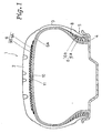
- Fig.1 is a cross sectional view of a tyre according to the present invention;
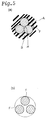
- Fig.2 is a perspective view of a cord used for the belt thereof;
- Fig.3 is a cross sectional view of an opened part of the belt cord;
- Fig.4a is a plan view of a waved monofilament used in the belt cord;
- Fig.4b is a plan view of an unwaved monofilament used in the belt cords;
- Fig.5a is a cross sectional view of a prior art closed belt cord;
- Fig.5b is a cross sectional view of an open or loose prior art belt cords;
- In Fig.1, a
pneumatic tyre 1 has atread 2, a pair ofbead portions 5, and a pair ofsidewalls 3 extending between the tread edges and thebead portions 5. - A bead core 4 is disposed in each
bead portion 5, acarcass 6 extends between thebead portions 5 being turned up around each bead core 4 to form a carcass turned up portion 6b and a main carcass portion 6a, and a belt 9 (in this embodiment comprising two belt plies 9A and 9B) is disposed radially outside thecarcass 6 under thetread 2. - The
carcass 6 comprises at least oneply 6A of cords laid at 75 to 90 degrees with respect to the tyre equator. - Between the main carcass portion 6a and each of the turned up portions 6b, a bead apex 8 made of hard rubber is disposed. The bead apexes 8 extend taperingly radially outwardly from the bead cores 4 to reinforce the
bead portion 5 andlower sidewall 3 and thus to increase the lateral stiffness of the tyre. - The
carcass 6 in this embodiment is composed of oneply 6A of nylon fibre cords. - For the carcass, organic fibre cords, e.g. polyester, rayon, aromatic polyamide or the like, are preferably used. However, steel cords can be used.
- In this embodiment, the radially inner belt ply 9A disposed on the
carcass 6 is wider than the radially outer belt ply 9B disposed on the inner belt ply 9A. Thebelt 9 as a whole has enough width to reinforce the whole width of thetread 2. - Each of the belt plies 9A and 9B is made of
parallel cords 10 embedded in toppingrubber 11 and laid at an angle (theta) from 0 to 35 degrees with respect to the tyre equator, the two plies being arranged such that the cords in the inner belt ply 9A cross the cords in the outer belt ply 9B. - In the present invention, the
belt cords 10 comprise threesteel monofilaments 12 which are twisted together as shown in Fig.2, wherein at least one of the three steel monofilaments is waved, and at least one of the remaining two steel monofilaments is not waved. - Preferably, the
belt cord 10 is composed of one wavedmonofilament 12A and twounwaved monofilaments 12B. - Fig.4a and Fig.4b show a
waved monofilament 12A and anunwaved monofilament 12B, respectively, before they are twisted into a cord. As shown in Fig.4a, thewaved monofilament 12A is waved in advance. As shown in Fig.4b, theunwaved monofilament 12B is straight. - Accordingly, when they are twisted together as shown in Fig.2 and Fig.3a, the
resultant belt cord 10 has regions of no inter-filament contact, i.e. non-contacting portions P between theadjacent waved monofilament 12A andunwaved monofilament 12B. These occur along the length of the cord. Thus many openings or gaps T are formed, through which topping rubber may penetrate the central space of the cord. - The
waved monofilament 12A can be waved two-dimensionally by bending a straight monofilament in a flat plane at small pitches. - Alternatively, the
waved monofilament 12A can be waved three-dimensionally by coiling a straight monofilament at a small diameter and small pitches. - The wave pitches are preferably 0.31 to 0.70 times the final cord twist pitches.
- The wave height (peak to peak) of the initial waved cord is preferably 1.5 to 2.5 times the diameter (d) of the
monofilament 12A. - Generally, the diameters of the three
monofilaments - In the present invention, the
waved monofilament 12A and theunwaved monofilament 12B are twisted compactly so that the adjacent monofilaments generally contact each other. Accordingly, the elongation of the final cord is substantially smaller than that of the loose cord of the prior art. - The above mentioned gaps T at the noncontacting portions P is not more than 0.6 times the filament diameter d.
- In order to best improve steering stability and tyre uniformity, it is preferable that the elongation of the
belt cord 10 when tested at a 5 kgf load is less than 0.3%. - To achieve this and to provide the necessary strength for the belt, the diameter (d) of the
steel monofilaments rubber 11 preferably has a complex elastic modulus E* of 45 to 150 kgf/sq.cm. - Here, the complex elastic modulus E* is measured under the following conditions: 10% initial strain, 10 Hz sine wave with 2% amplitude, and at a temperature of 70 degrees C, using a test piece (4 mm width, 30 mm length, and 2 mm thickness), by a visco-elasticity spectrometer manufactured by IWAMOTO SEISAKUSYO.
- If the complex elastic modulus E* is less than 45 kgf/sq.cm, the belt rigidity becomes insufficient for steering stability, and the cut resistance of the belt cords during sharp cornering is decreased.
- If the complex elastic modulus E* is more than 150 kgf/sq.cm, it becomes difficult for the topping rubber to penetrate the cord.
- Further, the buckling strength coefficient K of each of the belts is more than 80 and less than 180.
- Here, the buckling strength coefficient K is defined by the cord count M per 5cm width divided by sine (theta). The angle (theta) is the belt cord angle with respect to the tyre equator.
- If the buckling strength coefficient K is not more than 80, the cut resistance of the belt cord during sharp cornering and the steering stability are deteriorated.
- If the buckling strength coefficient K is not less than 180, ride comfort is deteriorated, and the tyre weight is excessive.
- Test tyres of size 195/70R14 having the structure shown in Fig.1 and specifications given in Table 1 were prepared and tested. The test results are also given in Table 1.
- Penetration of the topping rubber into the belt cord was measured as follows:
Four belt cords were taken from the test tyre. - For each of the four belt cords, one of the three steel monofilaments therein was separated from the two others carefully so as not to remove the penetrated rubber using a sharp edged tool, and then the inner surfaces of the remaining two steel monofilaments were observed to determine whether the inner surfaces were exposed or not. Such determination was made every cord twisting pitch.
- If the surface was exposed, then the topping rubber had not penetrated the part (pitch).
- For each of the belt cords, the percentage of penetrated parts (twist pitches) was calculated from the following equation:

- From the calculated four values in each test tyre, the mean value thereof was obtained as the rubber penetration index for the tyre.
- The resistance to corrosion of the steel belt cords of each of the test tyres was measured as follows:
Eight holes reaching to the radially outer belt were made in the inside of the test tyre, and some salt water was put into the tyre cavity. Then the tyre was run for 30,000 km at a speed of 60 km/h under 120 % of the standard tyre load (the maximum load specified in JIS). After the 30,000 km test, the area of the corroded part of the radially inner belt was measured as the resistance to corrosion, and indicated by an index based on thatReference tyre 2 is 100. Therefore, the smaller the index, the better the resistance. - The cut resistance was evaluated by the cut caused by sharp cornering of the test car. In Table 2, the cut resistance is indicated by an index based on that
Reference tyre 2 is 100. The large the index, the better the resistance. - The steering stability and ride comfort were evaluated by a test driver into five ranks, wherein the rank three is standard. The larger the value, the better the performance.

Claims (6)
- A pneumatic tyre comprising a carcass (6) extending between bead portions (5) of the tyre, and a belt (9) disposed radially outside the carcass (6) under a tread (2), wherein the belt (9) comprises reinforcing cords (10) embedded in topping rubber at an angle (theta) to the tyre equator and each of the belt cords comprises three steel monofilaments (12), characterised in that the three steel monofilaments (12) include at least one waved steel monofilament (12A) and at least one unwaved steel monofilament (12B), said at least one waved steel monofilament (12A), said at least one unwaved steel monofilament (12B), and the remaining steel filament being compactly twisted together so as to make alternate contacting portions and noncontacting portions between said at least one waved steel monofilament (12A) and at least one of the remaining two steel monofilaments, and the gap (T) therebetween at each said noncontacting portion is not more than 0.6 times the diameter (d) of the waved steel monofilament (12A).
- A pneumatic tyre according to claim 1, characterised in that the diameter (d) of the waved steel monofilament is 0.2 to 0.35 mm.
- A pneumatic tyre according to claim 1 or 2, characterised in that the elongation of the belt cord under 5kgf load is not more than 0.3%.
- A pneumatic tyre according to claim 1, 2 or 3 characterised in that the topping rubber for the belt cords has a complex elastic modulus of 45 to 150 kgf/sq.cm.
- A pneumatic tyre according to any of claims 1 to 4, characterised in that the buckling strength coefficient K of the belt (9) is more than 80 and less than 180, wherein the buckling strength coefficient K is defined as the belt cord count per 5cm width of the belt divided by sine (theta), the angle (theta) is the belt cord angle to the tyre equator.
- A pneumatic tyre according to any of claims 1 to 5, characterised in that in each said belt cord (10), the pitches of the waving of said at least waved steel monofilament are less than the pitches of the cord twist.
Applications Claiming Priority (2)
| Application Number | Priority Date | Filing Date | Title |
|---|---|---|---|
| JP3148004A JP3038049B2 (en) | 1991-05-22 | 1991-05-22 | Pneumatic tire |
| JP148004/91 | 1991-05-22 |
Publications (2)
| Publication Number | Publication Date |
|---|---|
| EP0515178A1 true EP0515178A1 (en) | 1992-11-25 |
| EP0515178B1 EP0515178B1 (en) | 1995-07-19 |
Family
ID=15442961
Family Applications (1)
| Application Number | Title | Priority Date | Filing Date |
|---|---|---|---|
| EP19920304586 Expired - Lifetime EP0515178B1 (en) | 1991-05-22 | 1992-05-20 | Pneumatic tyre |
Country Status (3)
| Country | Link |
|---|---|
| EP (1) | EP0515178B1 (en) |
| JP (1) | JP3038049B2 (en) |
| DE (1) | DE69203535T2 (en) |
Cited By (3)
| Publication number | Priority date | Publication date | Assignee | Title |
|---|---|---|---|---|
| EP0543640A1 (en) * | 1991-11-21 | 1993-05-26 | Sumitomo Rubber Industries Limited | Pneumatic tyre |
| EP0604228A1 (en) * | 1992-12-25 | 1994-06-29 | Sumitomo Rubber Industries, Co. Ltd | Pneumatic tyre |
| US6691758B2 (en) | 1994-12-20 | 2004-02-17 | The Goodyear Tire & Rubber Company | Tires with high strength reinforcement |
Families Citing this family (3)
| Publication number | Priority date | Publication date | Assignee | Title |
|---|---|---|---|---|
| JP2719862B2 (en) * | 1991-12-27 | 1998-02-25 | トクセン工業株式会社 | Steel cord for reinforcing rubber products |
| KR101496019B1 (en) * | 2013-08-07 | 2015-02-25 | 한국타이어 주식회사 | Rubber rolled structure for reinforecing tire and vehicle tire comprising the same |
| KR101522467B1 (en) * | 2013-11-12 | 2015-05-21 | 금호타이어 주식회사 | Steel cord for pneumatic radial tyre and pneumatic radial tyre thereof |
Citations (8)
| Publication number | Priority date | Publication date | Assignee | Title |
|---|---|---|---|---|
| FR1293015A (en) * | 1961-03-23 | 1962-05-11 | Kleber Colombes | Elastic wire rope |
| US4738096A (en) * | 1986-01-17 | 1988-04-19 | Tokyo Rope Mfg. Co., Ltd. | Metal cord |
| EP0317636A1 (en) * | 1987-06-08 | 1989-05-31 | Bridgestone Corporation | Heavy-load radial tire |
| US4836262A (en) * | 1986-08-08 | 1989-06-06 | Bridgestone Corporation | Metal cords and pneumatic tires using the same |
| EP0414892A1 (en) * | 1989-03-08 | 1991-03-06 | Bridgestone Corporation | Pneumatic radial tire |
| WO1991004370A1 (en) * | 1989-09-18 | 1991-04-04 | B.V. Bekaert S.A. | Open cord structure |
| EP0433962A1 (en) * | 1989-12-20 | 1991-06-26 | Tokusen Kogyo Company Limited | Steel cord for reinforcement of rubber products |
| EP0462716A1 (en) * | 1990-06-16 | 1991-12-27 | Tokusen Kogyo Company Limited | Steel cord for reinforcing rubber product |
-
1991
- 1991-05-22 JP JP3148004A patent/JP3038049B2/en not_active Expired - Fee Related
-
1992
- 1992-05-20 EP EP19920304586 patent/EP0515178B1/en not_active Expired - Lifetime
- 1992-05-20 DE DE1992603535 patent/DE69203535T2/en not_active Expired - Fee Related
Patent Citations (8)
| Publication number | Priority date | Publication date | Assignee | Title |
|---|---|---|---|---|
| FR1293015A (en) * | 1961-03-23 | 1962-05-11 | Kleber Colombes | Elastic wire rope |
| US4738096A (en) * | 1986-01-17 | 1988-04-19 | Tokyo Rope Mfg. Co., Ltd. | Metal cord |
| US4836262A (en) * | 1986-08-08 | 1989-06-06 | Bridgestone Corporation | Metal cords and pneumatic tires using the same |
| EP0317636A1 (en) * | 1987-06-08 | 1989-05-31 | Bridgestone Corporation | Heavy-load radial tire |
| EP0414892A1 (en) * | 1989-03-08 | 1991-03-06 | Bridgestone Corporation | Pneumatic radial tire |
| WO1991004370A1 (en) * | 1989-09-18 | 1991-04-04 | B.V. Bekaert S.A. | Open cord structure |
| EP0433962A1 (en) * | 1989-12-20 | 1991-06-26 | Tokusen Kogyo Company Limited | Steel cord for reinforcement of rubber products |
| EP0462716A1 (en) * | 1990-06-16 | 1991-12-27 | Tokusen Kogyo Company Limited | Steel cord for reinforcing rubber product |
Cited By (6)
| Publication number | Priority date | Publication date | Assignee | Title |
|---|---|---|---|---|
| EP0543640A1 (en) * | 1991-11-21 | 1993-05-26 | Sumitomo Rubber Industries Limited | Pneumatic tyre |
| US5472033A (en) * | 1991-11-21 | 1995-12-05 | Sumitomo Rubber Industries, Ltd. | Pneumatic tire with belt cords comprising four steel monofilaments one or two of which are waved |
| EP0604228A1 (en) * | 1992-12-25 | 1994-06-29 | Sumitomo Rubber Industries, Co. Ltd | Pneumatic tyre |
| US6691758B2 (en) | 1994-12-20 | 2004-02-17 | The Goodyear Tire & Rubber Company | Tires with high strength reinforcement |
| US6857458B2 (en) | 1994-12-20 | 2005-02-22 | The Goodyear Tire & Rubber Company | Tires with high strength reinforcement |
| US7082978B2 (en) | 1994-12-20 | 2006-08-01 | The Goodyear Tire & Rubber Company | Tires with high strength reinforcement |
Also Published As
| Publication number | Publication date |
|---|---|
| EP0515178B1 (en) | 1995-07-19 |
| DE69203535D1 (en) | 1995-08-24 |
| JPH05246206A (en) | 1993-09-24 |
| JP3038049B2 (en) | 2000-05-08 |
| DE69203535T2 (en) | 1996-01-11 |
Similar Documents
| Publication | Publication Date | Title |
|---|---|---|
| EP0543640B1 (en) | Pneumatic tyre | |
| US5858137A (en) | Radial tires having at least two belt plies reinforced with steel monofilaments | |
| EP0661179A1 (en) | Pneumatic radial tyre | |
| EP0157716A1 (en) | Flat wire reinforcement in tyre belt and carcass | |
| US5419383A (en) | Pneumatic tire including hybrid belt cord | |
| EP1961860A1 (en) | Steel cord for reinforcing rubber article and pneumatic radial tire | |
| US6959745B2 (en) | Steel cord, method of making the same and pneumatic tire including the same | |
| EP2246201B1 (en) | Pneumatic radial tire | |
| EP3381714B1 (en) | Motorcycle tire | |
| EP2018978A1 (en) | Pneumatic tire | |
| US20030010418A1 (en) | Pneumatic tire | |
| US6267165B1 (en) | Pneumatic tire with specified aramid belt | |
| EP1406773B9 (en) | Tyre for motor vehicles with undulated monofilaments in belt reinforcement layer | |
| US7493748B2 (en) | Pneumatic tire with metal cord and method of manufacturing metal cord | |
| EP1256652B1 (en) | Metallic cord | |
| US4749016A (en) | Radial tire having an improving durability | |
| EP0604228B1 (en) | Pneumatic tyre | |
| EP0515178B1 (en) | Pneumatic tyre | |
| US6425428B1 (en) | Steel cord having flat side surface portion, method of manufacturing same, and pneumatic tire reinforced with same | |
| EP1262337A2 (en) | Pneumatic tire | |
| EP1063346B1 (en) | Steel cords for reinforcement of rubber articles, in particular pneumatic tires | |
| US5911675A (en) | Steel cord for reinforcing rubber product and pneumatic tire using such steel cord | |
| US20220126629A1 (en) | Pneumatic radial tire | |
| CN114056008A (en) | Shear band structure for tire | |
| JP2001003280A (en) | Steel cord for reinforcing rubber product and pneumatic radial tire |
Legal Events
| Date | Code | Title | Description |
|---|---|---|---|
| PUAI | Public reference made under article 153(3) epc to a published international application that has entered the european phase |
Free format text: ORIGINAL CODE: 0009012 |
|
| AK | Designated contracting states |
Kind code of ref document: A1 Designated state(s): DE FR GB |
|
| 17P | Request for examination filed |
Effective date: 19930302 |
|
| 17Q | First examination report despatched |
Effective date: 19941028 |
|
| GRAA | (expected) grant |
Free format text: ORIGINAL CODE: 0009210 |
|
| STAA | Information on the status of an ep patent application or granted ep patent |
Free format text: STATUS: THE PATENT HAS BEEN GRANTED |
|
| AK | Designated contracting states |
Kind code of ref document: B1 Designated state(s): DE FR GB |
|
| REF | Corresponds to: |
Ref document number: 69203535 Country of ref document: DE Date of ref document: 19950824 |
|
| ET | Fr: translation filed | ||
| PLBE | No opposition filed within time limit |
Free format text: ORIGINAL CODE: 0009261 |
|
| 26N | No opposition filed | ||
| REG | Reference to a national code |
Ref country code: GB Ref legal event code: IF02 |
|
| PGFP | Annual fee paid to national office [announced via postgrant information from national office to epo] |
Ref country code: DE Payment date: 20070517 Year of fee payment: 16 |
|
| PGFP | Annual fee paid to national office [announced via postgrant information from national office to epo] |
Ref country code: GB Payment date: 20070516 Year of fee payment: 16 |
|
| PGFP | Annual fee paid to national office [announced via postgrant information from national office to epo] |
Ref country code: FR Payment date: 20070510 Year of fee payment: 16 |
|
| GBPC | Gb: european patent ceased through non-payment of renewal fee |
Effective date: 20080520 |
|
| REG | Reference to a national code |
Ref country code: FR Ref legal event code: ST Effective date: 20090119 |
|
| PG25 | Lapsed in a contracting state [announced via postgrant information from national office to epo] |
Ref country code: FR Free format text: LAPSE BECAUSE OF NON-PAYMENT OF DUE FEES Effective date: 20080602 Ref country code: DE Free format text: LAPSE BECAUSE OF NON-PAYMENT OF DUE FEES Effective date: 20081202 |
|
| PG25 | Lapsed in a contracting state [announced via postgrant information from national office to epo] |
Ref country code: GB Free format text: LAPSE BECAUSE OF NON-PAYMENT OF DUE FEES Effective date: 20080520 |