EP0514918B1 - Device for exhausting the fumes forming inside accumulator batteries - Google Patents
Device for exhausting the fumes forming inside accumulator batteries Download PDFInfo
- Publication number
- EP0514918B1 EP0514918B1 EP92108660A EP92108660A EP0514918B1 EP 0514918 B1 EP0514918 B1 EP 0514918B1 EP 92108660 A EP92108660 A EP 92108660A EP 92108660 A EP92108660 A EP 92108660A EP 0514918 B1 EP0514918 B1 EP 0514918B1
- Authority
- EP
- European Patent Office
- Prior art keywords
- chamber
- accumulator
- explosion
- disc
- lid
- Prior art date
- Legal status (The legal status is an assumption and is not a legal conclusion. Google has not performed a legal analysis and makes no representation as to the accuracy of the status listed.)
- Expired - Lifetime
Links
Images

Classifications
-
- H—ELECTRICITY
- H01—ELECTRIC ELEMENTS
- H01M—PROCESSES OR MEANS, e.g. BATTERIES, FOR THE DIRECT CONVERSION OF CHEMICAL ENERGY INTO ELECTRICAL ENERGY
- H01M50/00—Constructional details or processes of manufacture of the non-active parts of electrochemical cells other than fuel cells, e.g. hybrid cells
- H01M50/10—Primary casings, jackets or wrappings of a single cell or a single battery
- H01M50/147—Lids or covers
-
- H—ELECTRICITY
- H01—ELECTRIC ELEMENTS
- H01M—PROCESSES OR MEANS, e.g. BATTERIES, FOR THE DIRECT CONVERSION OF CHEMICAL ENERGY INTO ELECTRICAL ENERGY
- H01M50/00—Constructional details or processes of manufacture of the non-active parts of electrochemical cells other than fuel cells, e.g. hybrid cells
- H01M50/30—Arrangements for facilitating escape of gases
- H01M50/35—Gas exhaust passages comprising elongated, tortuous or labyrinth-shaped exhaust passages
- H01M50/367—Internal gas exhaust passages forming part of the battery cover or case; Double cover vent systems
-
- H—ELECTRICITY
- H01—ELECTRIC ELEMENTS
- H01M—PROCESSES OR MEANS, e.g. BATTERIES, FOR THE DIRECT CONVERSION OF CHEMICAL ENERGY INTO ELECTRICAL ENERGY
- H01M50/00—Constructional details or processes of manufacture of the non-active parts of electrochemical cells other than fuel cells, e.g. hybrid cells
- H01M50/30—Arrangements for facilitating escape of gases
- H01M50/383—Flame arresting or ignition-preventing means
-
- H—ELECTRICITY
- H01—ELECTRIC ELEMENTS
- H01M—PROCESSES OR MEANS, e.g. BATTERIES, FOR THE DIRECT CONVERSION OF CHEMICAL ENERGY INTO ELECTRICAL ENERGY
- H01M50/00—Constructional details or processes of manufacture of the non-active parts of electrochemical cells other than fuel cells, e.g. hybrid cells
- H01M50/30—Arrangements for facilitating escape of gases
- H01M50/394—Gas-pervious parts or elements
-
- Y—GENERAL TAGGING OF NEW TECHNOLOGICAL DEVELOPMENTS; GENERAL TAGGING OF CROSS-SECTIONAL TECHNOLOGIES SPANNING OVER SEVERAL SECTIONS OF THE IPC; TECHNICAL SUBJECTS COVERED BY FORMER USPC CROSS-REFERENCE ART COLLECTIONS [XRACs] AND DIGESTS
- Y02—TECHNOLOGIES OR APPLICATIONS FOR MITIGATION OR ADAPTATION AGAINST CLIMATE CHANGE
- Y02E—REDUCTION OF GREENHOUSE GAS [GHG] EMISSIONS, RELATED TO ENERGY GENERATION, TRANSMISSION OR DISTRIBUTION
- Y02E60/00—Enabling technologies; Technologies with a potential or indirect contribution to GHG emissions mitigation
- Y02E60/10—Energy storage using batteries
Definitions
- the invention concerns an accumulator lid having a device for exhausting the fumes forming inside accumulator batteries.
- Said antiexplosion device consists of a disc comprised in the state of the art technique which is made of a material allowing the fumes inside the accumulator to be exhausted, but preventing the entrance into the exhaust ducts of the lid of incidental flames and sparks, which would cause its explosion.
- this anti-explosion disc is held in a container which is an integral part of the joint applied in the opening of the exhaust duct.
- said disc is arranged between the union connecting the joint with the outlet opening of the exhaust duct and the hose conveying the fumes away from the accumulator.
- the anti-explosion disc is part of the lid of the accumulator and it is positioned within a chamber near the outlet opening of the exhaust ducts.
- the patent document WO-A-8604186 discloses a lid for accumulators in which are present channels for conveying gas with an hopper having a gas permeable disc disposed substantially horizzontally and, consequently, invested directly by all gas going out of the accumulator.
- the device according to the present invention has the main purpose of warranting the constant exhaust of the fumes from the interior of the accumulator, even in the case of condensation on the anti-explosion disc of the vaporized electrolyte, which has found its way into the fume exhaust ducts, during the evacuation phase to the exterior.
- a lid for an accumulator having an exhaust of the fumes forming inside the accumulator with the main features thereof as indicated in the preamble of claim 1, the essential inventive features of said lid being as defined in the characterizing part of claim 1.
- the chamber containing the anti-explosion disc has a cylindrical shape and it is provided in the vertical wall of the peripheral rim of the lid, in correspondence with the outlet opening of each exhaust duct.
- the removable cap pushes the anti-explosion disc flush against the shoulder and it is inserted in the cylindrical chamber with an interference, so as to achieve, in correspondence with the lateral surface of mutual contact, the tightness with the cylindrical chamber.
- the anti-explosion disc also achieves the tightness with its lateral surface, which interferes with the inner lateral surface of the cylindrical chamber containing it.
- the cap is provided with an annular recess lodging the anti-explosion disc.
- the device according to the invention insures both the backflow of the condensed electrolyte into the accumulator, and the continued discharge of the exhaust fumes.
- the possibility for the anti-explosion disc to clog is, therefore, eliminated, while, at the same time, the efficiency of the fume-exhaust system is guaranteed.
- the device according to the invention also advantageously prevents the electrolyte from dripping out of the accumulator.
- the exhaust device according to the invention is applied on an accumulator lid, indicated as a whole with 2, which presents a plurality of re-fill openings 3, which are connected to one another through a plurality of exhaust ducts 4, which, as can be observed in Fig. 2, have been obtained in the upper wall 5 of the accumulator lid 2, near its inner surface 23 facing the interior of the accumulator.
- the anti-explosion disc 11 is pushed flush by the pressure of the annular rim 13 of cap 12 inserted in the cylindrical chamber 7.
- Said cap 12 presents also an interference with the cylindrical chamber 7 wherein it is inserted in correspondence with the lateral walls 24 in mutual contact with each other and, as a consequence, cap 12 is tightly connected with the cylindrical chamber 7.
- Said interference between cap 12 and the cylindrical chamber 7 holds disc 11 within the cylindrical chamber with a force which counteracts the inner pressure produced by the fumes forming inside the accumulator.
- By suitably adjusting the value of said interference it is possible to pre-set the maximum pressure threshold, beyond which disc 11 and cap 12 are pushed out of cylindrical chamber 7, so that the device according to the invention also acquires the characteristics of a safety valve.
- the anti-explosion disc 11, in correspondence with its lateral surface 22 is also tightly inserted into said cylindrical chamber 7.
- cap 12 presents an opening 14, into which a joint (not represented in the drawing) with a hose is inserted. This has the task of conveying the fumes out of the accumulator. In fact, through the re-fill openings 3, which are shut by the caps 15, the fumes forming inside the cells of the accumulator are conveyed following direction 16 into the exhaust ducts 4 and from here, going through hole 9 and the anti-explosion disc 11, they are conveyed outside.
- Fig. 3 shows a different embodiment of the invention.
- This embodiment varies from the previously described one, in that the anti-explosion disc 30 is lodged in the annular recess of cap 31, positioned at the end of the exhaust duct 32 of the lid 40.
- there is a pre-chamber 33 which collects the condensed electrolyte vapor and presents a hole 34 at its bottom, having the purpose of discharging the electrolyte which has condensed in the pre-chamber.
- One or more of the described devices can be applied on the accumulator lid, i.e. it will be possible to realize in correspondence with each exhaust duct a cylindrical chamber suited to lodge an anti-explosion disc or, should the exhaust duct be central, as described in the Italian patent application No. VI91A000089, the device will be single and it will be applied in the single central duct.
- the device according to the invention may undergo changes and modifications having the purpose of improving its efficiency and to make its manufacture easier. Said changes and modifications will, however, not exceed the scope protected by the present invention.
Abstract
Description
- The invention concerns an accumulator lid having a device for exhausting the fumes forming inside accumulator batteries.
- It is a known fact that, particularly in lead accumulator batteries, during their working stage and/or during the recharging stage, fumes form which must be exhausted since, if that is not done, they would cause an inflating of the accumulator with the consequent possible breakage of the same. For this reason the lids are provided with exhaust ducts which connect with one another the refill openings of the accumulator lid and connect them to the exterior through outlet openings. In one or more of said outlet openings a connection complete with a hose is provided for the conveyance of the fumes to the exterior.
- Since the fumes forming inside the accumulator also contain highly explosive hydrogen, in some cases it is necessary to also apply an anti-explosion device which, should flames or sparkles be present in the room around the accumulator, has the purpose of preventing the flames or the sparkles from entering into the accumulator through the exhaust ducts and causing the explosion by igniting the fumes which are present within the exhaust ducts of the lid. Said antiexplosion device consists of a disc comprised in the state of the art technique which is made of a material allowing the fumes inside the accumulator to be exhausted, but preventing the entrance into the exhaust ducts of the lid of incidental flames and sparks, which would cause its explosion.
- In some constructions this anti-explosion disc is held in a container which is an integral part of the joint applied in the opening of the exhaust duct. In particular, said disc is arranged between the union connecting the joint with the outlet opening of the exhaust duct and the hose conveying the fumes away from the accumulator.
- On the other hand, in some other embodiments comprised in the state of the art, the anti-explosion disc is part of the lid of the accumulator and it is positioned within a chamber near the outlet opening of the exhaust ducts.
- The patent document WO-A-8604186 discloses a lid for accumulators in which are present channels for conveying gas with an hopper having a gas permeable disc disposed substantially horizzontally and, consequently, invested directly by all gas going out of the accumulator.
- In both types of embodiment there is the inconvenience that, since the anti-explosion disc is permeable to fumes but not to liquids, it clogs up whenever the condensation resulting from the electrolyte liquid, which is led into the fume-exhaust ducts in the vapor state, comes to rest on the point of connection of the disc. It is easy to understand how such an occurrence can cause remarkable inconveniences and also dangers, since, if this occurs, the fumes are not let out and they build up inside the accumulator. This entails, as has already been said, the inflating of the accumulator and its ensuing deformation.
- In order to avoid this inconvenience, the device according to the present invention has the main purpose of warranting the constant exhaust of the fumes from the interior of the accumulator, even in the case of condensation on the anti-explosion disc of the vaporized electrolyte, which has found its way into the fume exhaust ducts, during the evacuation phase to the exterior.
- The described purpose is reached by providing a lid for an accumulator having an exhaust of the fumes forming inside the accumulator with the main features thereof as indicated in the preamble of
claim 1, the essential inventive features of said lid being as defined in the characterizing part ofclaim 1. - According to a preferred embodiment, the chamber containing the anti-explosion disc has a cylindrical shape and it is provided in the vertical wall of the peripheral rim of the lid, in correspondence with the outlet opening of each exhaust duct.
- In one example of embodiment of the invention, the removable cap pushes the anti-explosion disc flush against the shoulder and it is inserted in the cylindrical chamber with an interference, so as to achieve, in correspondence with the lateral surface of mutual contact, the tightness with the cylindrical chamber.
- The anti-explosion disc also achieves the tightness with its lateral surface, which interferes with the inner lateral surface of the cylindrical chamber containing it.
- In another embodiment of the invention the cap is provided with an annular recess lodging the anti-explosion disc.
- Advantageously, in the case of condensation of the electrolyte forming on the anti-explosion disc, the device according to the invention insures both the backflow of the condensed electrolyte into the accumulator, and the continued discharge of the exhaust fumes. The possibility for the anti-explosion disc to clog is, therefore, eliminated, while, at the same time, the efficiency of the fume-exhaust system is guaranteed.
- Moreover, the device according to the invention also advantageously prevents the electrolyte from dripping out of the accumulator.
- Further scope of applicability of the present invention will become apparent from the detailed description given hereinafter. However, it should be understood that the detailed description and specific examples, while indicating preferred embodiments of the invention, are given by way of illustration only, wherein:
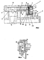
- Fig. 1 is a top view of an accumulator lid to which the device for the fume exhaust according to the invention has been applied;
- Fig. 2 is the magnified view of a vertical section made in the lid in correspondence with an exhaust duct in which the exhaust device according to the invention has been applied;
- Fig. 3 shows in a cross-section a different embodiment of the fume-exhaust device according to the invention.
- As can be observed in Fig. 1, the exhaust device according to the invention, indicated as a whole with 1, is applied on an accumulator lid, indicated as a whole with 2, which presents a plurality of
re-fill openings 3, which are connected to one another through a plurality of exhaust ducts 4, which, as can be observed in Fig. 2, have been obtained in theupper wall 5 of theaccumulator lid 2, near itsinner surface 23 facing the interior of the accumulator. - In correspondence with the
lateral wall 21 oflid 2, at the spot where said ducts 4 communicate with the outside environment, there is, as can be seen in Fig. 2, acylindrical chamber 7, the bottom 8 of which communicates through a hole 9, with one of the exhaust ducts 4, while its lateral inner surface presents in an intermediate position ashoulder 10. Against thisshoulder 10 theanti-explosion disc 11 is pushed flush by the pressure of theannular rim 13 ofcap 12 inserted in thecylindrical chamber 7. - Said
cap 12 presents also an interference with thecylindrical chamber 7 wherein it is inserted in correspondence with thelateral walls 24 in mutual contact with each other and, as a consequence,cap 12 is tightly connected with thecylindrical chamber 7. Said interference betweencap 12 and thecylindrical chamber 7 holdsdisc 11 within the cylindrical chamber with a force which counteracts the inner pressure produced by the fumes forming inside the accumulator. By suitably adjusting the value of said interference, it is possible to pre-set the maximum pressure threshold, beyond whichdisc 11 andcap 12 are pushed out ofcylindrical chamber 7, so that the device according to the invention also acquires the characteristics of a safety valve. Moreover, theanti-explosion disc 11, in correspondence with itslateral surface 22 is also tightly inserted into saidcylindrical chamber 7. - The middle of
cap 12 presents anopening 14, into which a joint (not represented in the drawing) with a hose is inserted. This has the task of conveying the fumes out of the accumulator. In fact, through there-fill openings 3, which are shut by thecaps 15, the fumes forming inside the cells of the accumulator are conveyed followingdirection 16 into the exhaust ducts 4 and from here, going through hole 9 and theanti-explosion disc 11, they are conveyed outside. - During said fume exhaust, part of the electrolyte turns into vapor and is entrained by the fumes, following
direction 16, along the exhaust ducts 4, until it reaches theanti-explosion disc 11, where it stops and condenses. This is the reason why the describedshoulder 10, againts which disc (11) is placed, has been made in thecylindrical chamber 7; so thatsurface 20 ofdisc 11 and bottom 8 of thecylindrical chamber 7 define a pre-chamber 18 which collects the condensing electrolyte vapor, which then falls back down, followingdirection 19, into one or more accumulator cells going throughhole 17. Hence there is no chance of liquid building up close to theanti-explosion disc 11, which can continue its fume-exhausting activity, keeping its efficiency unchanged in time, thus reaching the purpose proposed by the invention. - The dripping of electrolyte in the outside environment is also prevented. Also, should there be an overpressure build-up, when the same exceeds the value of the interference of
cap 12 inchamber 7,cap 12 anddisc 11 are pushed out ofchamber 7, so that the exhaust device also acts as a safety valve. - Fig. 3 shows a different embodiment of the invention. This embodiment varies from the previously described one, in that the
anti-explosion disc 30 is lodged in the annular recess ofcap 31, positioned at the end of theexhaust duct 32 of thelid 40. In this case, too, there is a pre-chamber 33 which collects the condensed electrolyte vapor and presents a hole 34 at its bottom, having the purpose of discharging the electrolyte which has condensed in the pre-chamber. - One or more of the described devices can be applied on the accumulator lid, i.e. it will be possible to realize in correspondence with each exhaust duct a cylindrical chamber suited to lodge an anti-explosion disc or, should the exhaust duct be central, as described in the Italian patent application No. VI91A000089, the device will be single and it will be applied in the single central duct.
- During the manufacturing stage the device according to the invention may undergo changes and modifications having the purpose of improving its efficiency and to make its manufacture easier. Said changes and modifications will, however, not exceed the scope protected by the present invention.
Claims (5)
- An accumulator lid (2) comprising:- a plurality of re-fill openings (3), connected to one another through a plurality of exhaust ducts (4,32);- a lateral chamber (7), in correspondence with a lateral wall (21) of the accumulator lid (2) communicating on one side with at least one exhaust duct (4,32) and, on the opposite side, communicating with the outside environment;- an anti-explosion disc (11,30) placed within said chamber (7) in substantially vertical position;- a removable cap (12,31) presenting a central through-going opening (14), inserted in the chamber (7) and adhering against the anti-explosion disc,characterized in that said chamber (7) presents a pre-chamber (18) defined between the side of said lateral chamber (7) communicating with said at least one exhaust duct and the surface of the anti-explosion disc (11,30), said pre-chamber (18) collecting the condensed electrolyte through a through-going hole (17,34) into the underlying accumulator cells.
- A device according to claim 1, characterized in that the removable cap (12) is inserted in chamber (7) with a junction which interferes in correspondence with the lateral surfaces in mutual contact between said cap (12) and said chamber (7).
- A device according to claim 1, characterized in that the anti-explosion disc (11) is comprised between a shoulder (10), which is present in the chamber (7), and the cap (12).
- A device according to claim 1, characterized in that the anti-explosion disc (30) is inserted through pressure into a cylindrical recess of the cap (31).
- A device according to claim 4, characterized in that the chamber (7) is placed centrally in the lateral wall (21) of the lid (2).
Applications Claiming Priority (5)
| Application Number | Priority Date | Filing Date | Title |
|---|---|---|---|
| ITVI910087 | 1991-05-23 | ||
| ITVI910087A IT1247085B (en) | 1991-05-23 | 1991-05-23 | DEVICE FOR EXHAUSTING THE GAS PRODUCED INSIDE THE ACCUMULATORS OUTSIDE |
| CA002077203A CA2077203C (en) | 1991-05-23 | 1992-08-31 | Device for exhausting the fumes forming inside accumulator batteries |
| US07/950,890 US5298344A (en) | 1991-05-23 | 1992-09-25 | Device for exhausting the fumes forming inside accumulation batteries |
| JP4278234A JPH0834097B2 (en) | 1991-05-23 | 1992-10-16 | Storage battery smoke exhaust system |
Publications (2)
| Publication Number | Publication Date |
|---|---|
| EP0514918A1 EP0514918A1 (en) | 1992-11-25 |
| EP0514918B1 true EP0514918B1 (en) | 1996-08-14 |
Family
ID=27426955
Family Applications (1)
| Application Number | Title | Priority Date | Filing Date |
|---|---|---|---|
| EP92108660A Expired - Lifetime EP0514918B1 (en) | 1991-05-23 | 1992-05-22 | Device for exhausting the fumes forming inside accumulator batteries |
Country Status (10)
| Country | Link |
|---|---|
| US (1) | US5298344A (en) |
| EP (1) | EP0514918B1 (en) |
| JP (1) | JPH0834097B2 (en) |
| AT (1) | ATE141444T1 (en) |
| CA (1) | CA2077203C (en) |
| DE (1) | DE69212705T2 (en) |
| DK (1) | DK0514918T3 (en) |
| ES (1) | ES2091974T3 (en) |
| GR (1) | GR3021524T3 (en) |
| IT (1) | IT1247085B (en) |
Families Citing this family (14)
| Publication number | Priority date | Publication date | Assignee | Title |
|---|---|---|---|---|
| DE9015535U1 (en) * | 1990-11-13 | 1991-03-14 | Moll, Peter J., 8623 Staffelstein, De | |
| IT1270423B (en) * | 1993-06-04 | 1997-05-05 | Ind Accumulatori Srl | COVER FOR LEAD-ACID BATTERIES |
| DE9312250U1 (en) * | 1993-08-17 | 1993-10-21 | Vb Autobatterie Gmbh | Multi-cell battery |
| IT1270754B (en) * | 1993-11-30 | 1997-05-07 | Olimpio Stocchiero | IMPROVED DEVICE FOR DISCHARGING OUTSIDE THE GASES PRODUCED INSIDE ACCUMULATORS |
| JP2967904B2 (en) * | 1994-03-01 | 1999-10-25 | 本田技研工業株式会社 | Gas exhaust device for battery for electric vehicle |
| DE9407172U1 (en) * | 1994-04-29 | 1994-07-07 | Hagen Batterie Ag | Accumulator with degassing channel |
| ATE201116T1 (en) * | 1996-09-26 | 2001-05-15 | Akkumulatorenfabrik Moll Gmbh | BATTERY WITH A DEVICE FOR EXHAUSTING EXHAUST GASES |
| US6718996B2 (en) * | 2000-04-10 | 2004-04-13 | Club Car, Inc. | Filling pod for a battery, vehicle and method of supplying fluid to a battery |
| US6786226B2 (en) * | 2000-04-10 | 2004-09-07 | Club Car, Inc. | Battery fluid supply system |
| US7029786B2 (en) * | 2003-02-14 | 2006-04-18 | Flow-Rite Controls, Ltd. | Single point watering apparatus for lead-acid battery |
| JP5148862B2 (en) * | 2006-11-02 | 2013-02-20 | 古河電池株式会社 | Storage battery exhaust structure |
| JP5245335B2 (en) * | 2007-09-11 | 2013-07-24 | 株式会社Gsユアサ | Lead acid battery |
| DE102010022327A1 (en) * | 2010-06-01 | 2011-12-01 | Schaeffler Technologies Gmbh & Co. Kg | Device for setting environmental conditions for an electrical component |
| US9440601B2 (en) | 2013-09-06 | 2016-09-13 | Johnson Controls Technology Company | System for providing voltage measurements of battery cells to a PCB within a battery module |
Family Cites Families (13)
| Publication number | Priority date | Publication date | Assignee | Title |
|---|---|---|---|---|
| BE439052A (en) * | 1939-08-12 | 1900-01-01 | ||
| US3904441A (en) * | 1973-12-26 | 1975-09-09 | Eltra Corp | Battery vent construction |
| JPS5397440A (en) * | 1977-02-04 | 1978-08-25 | Toshiba Corp | Infrared rediator |
| JPS606071B2 (en) * | 1979-01-20 | 1985-02-15 | 古河電池株式会社 | Monoblock storage battery lid device and manufacturing method |
| JPS5837958A (en) * | 1981-08-31 | 1983-03-05 | Nec Corp | Semiconductor device |
| DE8430246U1 (en) * | 1984-10-15 | 1985-01-24 | Accumulatorenwerke Hoppecke Carl Zoellner & Sohn GmbH & Co KG, 5790 Brilon | LEAD ACCUMULATOR |
| NO845240L (en) * | 1984-12-27 | 1986-06-30 | Soennak Batterier | ELECTRIC ACCUMULATOR LID. |
| DE3729610A1 (en) * | 1987-09-04 | 1989-03-16 | Varta Batterie | Multi-cell battery with central degassing line integrated in the battery cover |
| US4851305A (en) * | 1988-02-18 | 1989-07-25 | Gnb Incorporated | Cover assemblies for electric storage batteries and batteries utilizing such cover assemblies |
| DE9005603U1 (en) * | 1990-05-17 | 1990-07-19 | Accumulatorenwerke Hoppecke Carl Zoellner & Sohn Gmbh & Co Kg, 5790 Brilon, De | |
| DE9015535U1 (en) * | 1990-11-13 | 1991-03-14 | Moll, Peter J., 8623 Staffelstein, De | |
| US5108853A (en) * | 1990-12-20 | 1992-04-28 | Exide Corporation | Submersible and flame retardant battery vent plug |
| GB9101402D0 (en) * | 1991-01-22 | 1991-03-06 | Lucas Ind Plc | Lid assembly |
-
1991
- 1991-05-23 IT ITVI910087A patent/IT1247085B/en active IP Right Grant
-
1992
- 1992-05-22 DE DE69212705T patent/DE69212705T2/en not_active Expired - Fee Related
- 1992-05-22 EP EP92108660A patent/EP0514918B1/en not_active Expired - Lifetime
- 1992-05-22 DK DK92108660.9T patent/DK0514918T3/en active
- 1992-05-22 AT AT92108660T patent/ATE141444T1/en not_active IP Right Cessation
- 1992-05-22 ES ES92108660T patent/ES2091974T3/en not_active Expired - Lifetime
- 1992-08-31 CA CA002077203A patent/CA2077203C/en not_active Expired - Fee Related
- 1992-09-25 US US07/950,890 patent/US5298344A/en not_active Expired - Fee Related
- 1992-10-16 JP JP4278234A patent/JPH0834097B2/en not_active Expired - Lifetime
-
1996
- 1996-10-31 GR GR960402887T patent/GR3021524T3/en unknown
Also Published As
| Publication number | Publication date |
|---|---|
| GR3021524T3 (en) | 1997-01-31 |
| ATE141444T1 (en) | 1996-08-15 |
| DE69212705D1 (en) | 1996-09-19 |
| IT1247085B (en) | 1994-12-12 |
| CA2077203A1 (en) | 1994-03-01 |
| JPH0834097B2 (en) | 1996-03-29 |
| US5298344A (en) | 1994-03-29 |
| CA2077203C (en) | 1997-05-27 |
| ES2091974T3 (en) | 1996-11-16 |
| ITVI910087A1 (en) | 1992-11-23 |
| ITVI910087A0 (en) | 1991-05-23 |
| DE69212705T2 (en) | 1997-03-20 |
| JPH06140013A (en) | 1994-05-20 |
| DK0514918T3 (en) | 1996-12-02 |
| EP0514918A1 (en) | 1992-11-25 |
Similar Documents
| Publication | Publication Date | Title |
|---|---|---|
| EP0514918B1 (en) | Device for exhausting the fumes forming inside accumulator batteries | |
| US5663010A (en) | Device to exhaust the fumes produced inside accumulator batteries | |
| JP4194242B2 (en) | Aerosol powder valve | |
| EP1298739B1 (en) | A vented-type leak-resistant motor cycle battery | |
| US5561001A (en) | Accumulator with degassing channel | |
| US10741803B2 (en) | Battery cover for retention of dielectric fluid | |
| US5846671A (en) | Lid for batteries | |
| EP1194962B1 (en) | Seal and bleed valve unit for electric batteries | |
| EP1383694B1 (en) | Improvements in valves for pressurised dispensing containers | |
| KR20080035507A (en) | Accumaulator | |
| GB2110099A (en) | Distillation and sublimation apparatus comprising a condenser | |
| US5853913A (en) | Re-filling and fume-discharging device for electric accumulator batteries | |
| US11101529B2 (en) | Battery cover for retention of dielectric fluid | |
| US20220013833A1 (en) | Secondary Battery | |
| US888469A (en) | Device for supplying scale-removal compounds to boilers. | |
| KR19990035737A (en) | Relief valve and manufacturing method thereof | |
| KR20210041991A (en) | Case for secondary battery, secondary battery including the same and method of manufacturing the case for secondary battery | |
| JPH10228891A (en) | Sealed lead-acid battery |
Legal Events
| Date | Code | Title | Description |
|---|---|---|---|
| PUAI | Public reference made under article 153(3) epc to a published international application that has entered the european phase |
Free format text: ORIGINAL CODE: 0009012 |
|
| AK | Designated contracting states |
Kind code of ref document: A1 Designated state(s): AT BE CH DE DK ES FR GB GR IT LI LU NL PT SE |
|
| 17P | Request for examination filed |
Effective date: 19930201 |
|
| 17Q | First examination report despatched |
Effective date: 19941118 |
|
| GRAH | Despatch of communication of intention to grant a patent |
Free format text: ORIGINAL CODE: EPIDOS IGRA |
|
| GRAA | (expected) grant |
Free format text: ORIGINAL CODE: 0009210 |
|
| AK | Designated contracting states |
Kind code of ref document: B1 Designated state(s): AT BE CH DE DK ES FR GB GR IT LI LU NL PT SE |
|
| REF | Corresponds to: |
Ref document number: 141444 Country of ref document: AT Date of ref document: 19960815 Kind code of ref document: T |
|
| REF | Corresponds to: |
Ref document number: 69212705 Country of ref document: DE Date of ref document: 19960919 |
|
| ITF | It: translation for a ep patent filed |
Owner name: STUDIO ING. E. BONINI S.R.L. |
|
| REG | Reference to a national code |
Ref country code: CH Ref legal event code: NV Representative=s name: KIRKER & CIE SA |
|
| ET | Fr: translation filed | ||
| REG | Reference to a national code |
Ref country code: ES Ref legal event code: FG2A Ref document number: 2091974 Country of ref document: ES Kind code of ref document: T3 |
|
| REG | Reference to a national code |
Ref country code: DK Ref legal event code: T3 |
|
| REG | Reference to a national code |
Ref country code: GR Ref legal event code: FG4A Free format text: 3021524 |
|
| REG | Reference to a national code |
Ref country code: PT Ref legal event code: SC4A Free format text: AVAILABILITY OF NATIONAL TRANSLATION Effective date: 19961031 |
|
| PLBE | No opposition filed within time limit |
Free format text: ORIGINAL CODE: 0009261 |
|
| STAA | Information on the status of an ep patent application or granted ep patent |
Free format text: STATUS: NO OPPOSITION FILED WITHIN TIME LIMIT |
|
| 26N | No opposition filed | ||
| PGFP | Annual fee paid to national office [announced via postgrant information from national office to epo] |
Ref country code: GR Payment date: 20000426 Year of fee payment: 9 |
|
| PGFP | Annual fee paid to national office [announced via postgrant information from national office to epo] |
Ref country code: PT Payment date: 20000427 Year of fee payment: 9 |
|
| PGFP | Annual fee paid to national office [announced via postgrant information from national office to epo] |
Ref country code: LU Payment date: 20000504 Year of fee payment: 9 |
|
| PGFP | Annual fee paid to national office [announced via postgrant information from national office to epo] |
Ref country code: AT Payment date: 20000516 Year of fee payment: 9 |
|
| PGFP | Annual fee paid to national office [announced via postgrant information from national office to epo] |
Ref country code: BE Payment date: 20000519 Year of fee payment: 9 |
|
| PGFP | Annual fee paid to national office [announced via postgrant information from national office to epo] |
Ref country code: DK Payment date: 20000530 Year of fee payment: 9 |
|
| PGFP | Annual fee paid to national office [announced via postgrant information from national office to epo] |
Ref country code: CH Payment date: 20000809 Year of fee payment: 9 |
|
| PG25 | Lapsed in a contracting state [announced via postgrant information from national office to epo] |
Ref country code: LU Free format text: LAPSE BECAUSE OF NON-PAYMENT OF DUE FEES Effective date: 20010522 Ref country code: DK Free format text: LAPSE BECAUSE OF NON-PAYMENT OF DUE FEES Effective date: 20010522 Ref country code: AT Free format text: LAPSE BECAUSE OF NON-PAYMENT OF DUE FEES Effective date: 20010522 |
|
| PG25 | Lapsed in a contracting state [announced via postgrant information from national office to epo] |
Ref country code: GR Free format text: LAPSE BECAUSE OF NON-PAYMENT OF DUE FEES Effective date: 20010531 Ref country code: BE Free format text: LAPSE BECAUSE OF NON-PAYMENT OF DUE FEES Effective date: 20010531 |
|
| PG25 | Lapsed in a contracting state [announced via postgrant information from national office to epo] |
Ref country code: LI Free format text: LAPSE BECAUSE OF NON-PAYMENT OF DUE FEES Effective date: 20010621 Ref country code: CH Free format text: LAPSE BECAUSE OF NON-PAYMENT OF DUE FEES Effective date: 20010621 |
|
| BERE | Be: lapsed |
Owner name: STOCCHIERO OLIMPIO Effective date: 20010531 |
|
| PG25 | Lapsed in a contracting state [announced via postgrant information from national office to epo] |
Ref country code: PT Free format text: LAPSE BECAUSE OF NON-PAYMENT OF DUE FEES Effective date: 20011130 |
|
| REG | Reference to a national code |
Ref country code: GB Ref legal event code: IF02 |
|
| REG | Reference to a national code |
Ref country code: CH Ref legal event code: PL |
|
| REG | Reference to a national code |
Ref country code: DK Ref legal event code: EBP |
|
| REG | Reference to a national code |
Ref country code: PT Ref legal event code: MM4A Free format text: LAPSE DUE TO NON-PAYMENT OF FEES Effective date: 20011130 |
|
| PGFP | Annual fee paid to national office [announced via postgrant information from national office to epo] |
Ref country code: FR Payment date: 20030508 Year of fee payment: 12 |
|
| PGFP | Annual fee paid to national office [announced via postgrant information from national office to epo] |
Ref country code: GB Payment date: 20030519 Year of fee payment: 12 |
|
| PGFP | Annual fee paid to national office [announced via postgrant information from national office to epo] |
Ref country code: ES Payment date: 20030527 Year of fee payment: 12 |
|
| PGFP | Annual fee paid to national office [announced via postgrant information from national office to epo] |
Ref country code: DE Payment date: 20030529 Year of fee payment: 12 |
|
| PGFP | Annual fee paid to national office [announced via postgrant information from national office to epo] |
Ref country code: SE Payment date: 20030530 Year of fee payment: 12 Ref country code: NL Payment date: 20030530 Year of fee payment: 12 |
|
| PG25 | Lapsed in a contracting state [announced via postgrant information from national office to epo] |
Ref country code: GB Free format text: LAPSE BECAUSE OF NON-PAYMENT OF DUE FEES Effective date: 20040522 |
|
| PG25 | Lapsed in a contracting state [announced via postgrant information from national office to epo] |
Ref country code: SE Free format text: LAPSE BECAUSE OF NON-PAYMENT OF DUE FEES Effective date: 20040523 |
|
| PG25 | Lapsed in a contracting state [announced via postgrant information from national office to epo] |
Ref country code: ES Free format text: LAPSE BECAUSE OF NON-PAYMENT OF DUE FEES Effective date: 20040524 |
|
| PG25 | Lapsed in a contracting state [announced via postgrant information from national office to epo] |
Ref country code: NL Free format text: LAPSE BECAUSE OF NON-PAYMENT OF DUE FEES Effective date: 20041201 Ref country code: DE Free format text: LAPSE BECAUSE OF NON-PAYMENT OF DUE FEES Effective date: 20041201 |
|
| EUG | Se: european patent has lapsed | ||
| GBPC | Gb: european patent ceased through non-payment of renewal fee |
Effective date: 20040522 |
|
| PG25 | Lapsed in a contracting state [announced via postgrant information from national office to epo] |
Ref country code: FR Free format text: LAPSE BECAUSE OF NON-PAYMENT OF DUE FEES Effective date: 20050131 |
|
| NLV4 | Nl: lapsed or anulled due to non-payment of the annual fee |
Effective date: 20041201 |
|
| REG | Reference to a national code |
Ref country code: FR Ref legal event code: ST |
|
| REG | Reference to a national code |
Ref country code: ES Ref legal event code: FD2A Effective date: 20040524 |
|
| PGFP | Annual fee paid to national office [announced via postgrant information from national office to epo] |
Ref country code: IT Payment date: 20060531 Year of fee payment: 15 |
|
| PG25 | Lapsed in a contracting state [announced via postgrant information from national office to epo] |
Ref country code: IT Free format text: LAPSE BECAUSE OF NON-PAYMENT OF DUE FEES Effective date: 20070522 |