EP0514604A2 - Repair of airfoil edges - Google Patents
Repair of airfoil edges Download PDFInfo
- Publication number
- EP0514604A2 EP0514604A2 EP91309996A EP91309996A EP0514604A2 EP 0514604 A2 EP0514604 A2 EP 0514604A2 EP 91309996 A EP91309996 A EP 91309996A EP 91309996 A EP91309996 A EP 91309996A EP 0514604 A2 EP0514604 A2 EP 0514604A2
- Authority
- EP
- European Patent Office
- Prior art keywords
- edge
- airfoil
- repaired
- area
- spanwise
- Prior art date
- Legal status (The legal status is an assumption and is not a legal conclusion. Google has not performed a legal analysis and makes no representation as to the accuracy of the status listed.)
- Granted
Links
Images

Classifications
-
- B—PERFORMING OPERATIONS; TRANSPORTING
- B23—MACHINE TOOLS; METAL-WORKING NOT OTHERWISE PROVIDED FOR
- B23P—METAL-WORKING NOT OTHERWISE PROVIDED FOR; COMBINED OPERATIONS; UNIVERSAL MACHINE TOOLS
- B23P6/00—Restoring or reconditioning objects
- B23P6/002—Repairing turbine components, e.g. moving or stationary blades, rotors
-
- B—PERFORMING OPERATIONS; TRANSPORTING
- B23—MACHINE TOOLS; METAL-WORKING NOT OTHERWISE PROVIDED FOR
- B23Q—DETAILS, COMPONENTS, OR ACCESSORIES FOR MACHINE TOOLS, e.g. ARRANGEMENTS FOR COPYING OR CONTROLLING; MACHINE TOOLS IN GENERAL CHARACTERISED BY THE CONSTRUCTION OF PARTICULAR DETAILS OR COMPONENTS; COMBINATIONS OR ASSOCIATIONS OF METAL-WORKING MACHINES, NOT DIRECTED TO A PARTICULAR RESULT
- B23Q35/00—Control systems or devices for copying directly from a pattern or a master model; Devices for use in copying manually
- B23Q35/04—Control systems or devices for copying directly from a pattern or a master model; Devices for use in copying manually using a feeler or the like travelling along the outline of the pattern, model or drawing; Feelers, patterns, or models therefor
- B23Q35/08—Means for transforming movement of the feeler or the like into feed movement of tool or work
- B23Q35/10—Means for transforming movement of the feeler or the like into feed movement of tool or work mechanically only
- B23Q35/101—Means for transforming movement of the feeler or the like into feed movement of tool or work mechanically only with a pattern composed of one or more lines used simultaneously for one tool
- B23Q35/105—Means for transforming movement of the feeler or the like into feed movement of tool or work mechanically only with a pattern composed of one or more lines used simultaneously for one tool of two lines
-
- F—MECHANICAL ENGINEERING; LIGHTING; HEATING; WEAPONS; BLASTING
- F01—MACHINES OR ENGINES IN GENERAL; ENGINE PLANTS IN GENERAL; STEAM ENGINES
- F01D—NON-POSITIVE DISPLACEMENT MACHINES OR ENGINES, e.g. STEAM TURBINES
- F01D5/00—Blades; Blade-carrying members; Heating, heat-insulating, cooling or antivibration means on the blades or the members
- F01D5/005—Repairing methods or devices
-
- Y—GENERAL TAGGING OF NEW TECHNOLOGICAL DEVELOPMENTS; GENERAL TAGGING OF CROSS-SECTIONAL TECHNOLOGIES SPANNING OVER SEVERAL SECTIONS OF THE IPC; TECHNICAL SUBJECTS COVERED BY FORMER USPC CROSS-REFERENCE ART COLLECTIONS [XRACs] AND DIGESTS
- Y10—TECHNICAL SUBJECTS COVERED BY FORMER USPC
- Y10T—TECHNICAL SUBJECTS COVERED BY FORMER US CLASSIFICATION
- Y10T29/00—Metal working
- Y10T29/49—Method of mechanical manufacture
- Y10T29/49316—Impeller making
- Y10T29/49318—Repairing or disassembling
-
- Y—GENERAL TAGGING OF NEW TECHNOLOGICAL DEVELOPMENTS; GENERAL TAGGING OF CROSS-SECTIONAL TECHNOLOGIES SPANNING OVER SEVERAL SECTIONS OF THE IPC; TECHNICAL SUBJECTS COVERED BY FORMER USPC CROSS-REFERENCE ART COLLECTIONS [XRACs] AND DIGESTS
- Y10—TECHNICAL SUBJECTS COVERED BY FORMER USPC
- Y10T—TECHNICAL SUBJECTS COVERED BY FORMER US CLASSIFICATION
- Y10T29/00—Metal working
- Y10T29/49—Method of mechanical manufacture
- Y10T29/49718—Repairing
- Y10T29/49748—Repairing by shaping, e.g., bending, extruding, turning, etc.
-
- Y—GENERAL TAGGING OF NEW TECHNOLOGICAL DEVELOPMENTS; GENERAL TAGGING OF CROSS-SECTIONAL TECHNOLOGIES SPANNING OVER SEVERAL SECTIONS OF THE IPC; TECHNICAL SUBJECTS COVERED BY FORMER USPC CROSS-REFERENCE ART COLLECTIONS [XRACs] AND DIGESTS
- Y10—TECHNICAL SUBJECTS COVERED BY FORMER USPC
- Y10T—TECHNICAL SUBJECTS COVERED BY FORMER US CLASSIFICATION
- Y10T409/00—Gear cutting, milling, or planing
- Y10T409/30—Milling
- Y10T409/306216—Randomly manipulated, work supported, or work following device
- Y10T409/306384—Randomly manipulated, work supported, or work following device with work supported guide means
- Y10T409/30644—Randomly manipulated, work supported, or work following device with work supported guide means to guide tool to move in arcuate path
-
- Y—GENERAL TAGGING OF NEW TECHNOLOGICAL DEVELOPMENTS; GENERAL TAGGING OF CROSS-SECTIONAL TECHNOLOGIES SPANNING OVER SEVERAL SECTIONS OF THE IPC; TECHNICAL SUBJECTS COVERED BY FORMER USPC CROSS-REFERENCE ART COLLECTIONS [XRACs] AND DIGESTS
- Y10—TECHNICAL SUBJECTS COVERED BY FORMER USPC
- Y10T—TECHNICAL SUBJECTS COVERED BY FORMER US CLASSIFICATION
- Y10T409/00—Gear cutting, milling, or planing
- Y10T409/30—Milling
- Y10T409/306664—Milling including means to infeed rotary cutter toward work
- Y10T409/30672—Milling including means to infeed rotary cutter toward work with means to limit penetration into work
Definitions
- This invention relates to the repair of gas turbine engine airfoils without removing the airfoil from the engine, and more particularly to the repair of BLISK fan blades.
- Leading and trailing edges of aircraft gas turbine engine rotor blade airfoils are subject to wear and damage that forms gouges and requires repair with a minimum of cost and difficulty. Repair of the airfoils conventionally requires their removal. However in combat as well as under other extenuating circumstances there is a need to field repair damaged airfoils without removing the blade or the engine from the aircraft. With the advent of blade integral disks or BLISKs there is an even greater need to repair the leading and trailing edges of the blade airfoils in the field while the engine is installed on the aircraft, either on the wing or in the fuselage, because blisk blades cannot easily be disassembled.
- the present invention provides a method and apparatus including a machine tool guide mountable to a hand held machine tool driver, such as a 90 degree angle head air motor, that drives a tool for cutting away damaged portions of the leading and trailing edges of the airfoil and machining and blending the damaged areas of the edges to within acceptable levels or tolerances.
- the tool guide includes a means to set the depth of the cut, which in one embodiment of the invention is an adjustable means, in order to prevent making too deep a cut in the airfoil edge.
- the preferred method of airfoil edge repair employs different tool guides, in accordance with the present invention, and different rotary tools for cutting and blending the damaged areas of the airfoil.
- First access to the airfoils is gained, preferably through a fan case access window on the engine, airfoils are visually inspected for damage, the depth of the damaged area is measured and the damaged airfoil is cleaned, preferably wiped clean using a suitable solvent, such as Methyl Ethyl Keytone, and a lint free cloth.
- a suitable solvent such as Methyl Ethyl Keytone, and a lint free cloth.
- a curved line is drawn around the damaged area wherein the marked off area preferably has a spanwise length eight times the depth of the deepest gouge and is equally spaced from the point of the deepest gouge.
- a mask is inserted into the access window on the fan case to protect adjoining airfoils from damage while machining and the delineated damaged area is rough machined away by the operator working through the access window, using an adjustable depth tool guide, of the present invention, mounted on a hand held air motor driving a straight edge rotary cutting tool and using smooth motions to prevent gouging and burning of the airfoil.
- one or more concave contoured edge rotary radius cutters of varying radii are set up in the air motor in conjunction with a second non-adjustable tool guide to machine a blend radius on the airfoil edge.
- Surfaces along the airfoil edges are then polished to form smooth blends using rubberized abrasive grinding wheels having a grinding surface contoured to form an acceptable leading or trailing edge radius.
- the entire reworked area is cleaned using a shop vacuum and wiped with a suitable solvent such as Methyl Ethyl Keytone. This procedure is repeated for all damaged airfoils.
- the apparatus and method of the present invention is a savings of time required to remove the damaged blades or in the case of BLISKs disassemble the engine, remove and fixture the rotor to allow the airfoil to be machined, and reassemble the rotor in the engine.
- Another advantage provided by the present invention is that it allows damaged blades to be simply and effectively repaired whereby an operator does not require a great deal of training.
- Yet another advantage provided by the present invention is a field level repair of damage to leading and trailing edges of rotor airfoils and particularly to BLISK type fan blades.
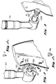
- FIG. 1 a portion of a gas turbine engine fan section 6 having a fan case 8 circumscribing a BLISK type fan rotor 10 having axially disposed circumferential rows of fan blade airfoils integrally formed thereon including damaged airfoils 12. Also shown is a damaged area 14 having gouges 16 located on a leading edge 18 of a damaged airfoil 12 and a similarly damaged trailing edge 19 on another damaged airfoil 12.
- FIG. 1 One embodiment of the invention illustrated in FIG. 1 is an adjustable cutting depth machine tool guide 30 mountable, by a mounting means such as mounting clamp 32, to a hand held machine tool driver, such as a 90 degree angle head air motor 34 available from ARO.
- Air motor 34 drives a straight edge rotary cutter 60 for rough cutting or machining away the damaged area of the leading and trailing edges 18 and 19 of airfoil 12.
- Adjustable tool guide 30 provides a flat platform 36 operable to rest against the side of airfoil 12 to allow machining of the edge.
- An adjustable stop means generally shown at 37 has two pins 42 mounted on a slidable base 40 operable to be translated by adjusting screw 46 and to be set by set screw 48.
- a slot 38 through which straight rotary cutter 60 is disposed allows the pins to set the depth of the cut of rotary cutter 60.
- a second embodiment of the invention illustrated in FIG. 2 is a fixed machine tool guide 130 shown to hand held 90 degree angle head air motor 34.
- This tooling has been found to be particularly useful for machining airfoil edge blend radii RM which may, as may be in the case of the original edge radius R, vary in length along the spanwise direction of the airfoil edge.
- Fixed tool guide 130 provides a flat platform 136 operable to rest against the side of airfoil 12 to allow machining of the edge blend radius RM.
- FIG. 1 also depicts part of a repair method of the preferred embodiment of the present invention wherein first access to the airfoils is gained through a fan case access window 9 on engine case 8, next airfoils 12 are visually inspected for damage, and the maximum depth D of the damaged area is measured, usually corresponding to the deepest gouge 20. Then the damaged airfoil is cleaned, preferably wiped clean using a suitable solvent such as Methyl Ethyl Keytone and a lint free cloth, and a curved line L is drawn around the damaged area wherein the marked off area to be removed X preferably has a spanwise length eight times the depth D of the deepest gouge 20 and is equally spaced from the point of the deepest gouge 20. Curved line L is preferably marked with a laboratory certified high purity marker and highlighted with masking tape.
- a suitable solvent such as Methyl Ethyl Keytone and a lint free cloth
- a mask (not shown) is inserted into the access window on the fan case to protect adjoining airfoils from damage while machining and the delineated area to be removed X is rough machined away by the operator working through the access window, using an adjustable depth tool guide 30, of the present invention, mounted on a hand held air motor 34 driving straight rotary cutting tool 60, as described previously.
- the depth of the cut is adjusted by turning adjusting screw 46 and set with set screw 48 according to the condition of area X.
- Area X is then removed with the machining apparatus previously described using smooth motions to prevent gouging and burning of the airfoil. This produces a repaired leading edge 18R (or alternatively a repaired trailing edge) with a new spanwise contour.
- At least one rotary radius cutter 138 having a concave contour 139 to produce an airfoil edge blend radius RM is set up in air motor 34 in conjunction with a non-adjustable tool guide 130.
- Blend radius RM may require two or more concave contour rotary radius cutters 138 of narrowing sizes to form the final blend radius in gradual steps. Using this tooling an airfoil edge blend radius RM is machined on the airfoil edge.
- the surfaces along the airfoil edge having blend radius RM are radiused and polished to form smooth blends using rubberized abrasive grinding wheels 238 having a grinding surface contoured to form an acceptable airfoil edge radius.
- the entire reworked area is cleaned using a shop vacuum and wiped using a suitable solvent such as Methyl Ethyl Keytone. This procedure is repeated for all damaged airfoils.
- airfoil edge repair process of the present invention is essentially the same for leading and trailing edges.
Abstract
Description
- This invention relates to the repair of gas turbine engine airfoils without removing the airfoil from the engine, and more particularly to the repair of BLISK fan blades.
- Leading and trailing edges of aircraft gas turbine engine rotor blade airfoils are subject to wear and damage that forms gouges and requires repair with a minimum of cost and difficulty. Repair of the airfoils conventionally requires their removal. However in combat as well as under other extenuating circumstances there is a need to field repair damaged airfoils without removing the blade or the engine from the aircraft. With the advent of blade integral disks or BLISKs there is an even greater need to repair the leading and trailing edges of the blade airfoils in the field while the engine is installed on the aircraft, either on the wing or in the fuselage, because blisk blades cannot easily be disassembled.
- The present invention provides a method and apparatus including a machine tool guide mountable to a hand held machine tool driver, such as a 90 degree angle head air motor, that drives a tool for cutting away damaged portions of the leading and trailing edges of the airfoil and machining and blending the damaged areas of the edges to within acceptable levels or tolerances. The tool guide includes a means to set the depth of the cut, which in one embodiment of the invention is an adjustable means, in order to prevent making too deep a cut in the airfoil edge.
- The preferred method of airfoil edge repair employs different tool guides, in accordance with the present invention, and different rotary tools for cutting and blending the damaged areas of the airfoil.
- First access to the airfoils is gained, preferably through a fan case access window on the engine, airfoils are visually inspected for damage, the depth of the damaged area is measured and the damaged airfoil is cleaned, preferably wiped clean using a suitable solvent, such as Methyl Ethyl Keytone, and a lint free cloth. A curved line is drawn around the damaged area wherein the marked off area preferably has a spanwise length eight times the depth of the deepest gouge and is equally spaced from the point of the deepest gouge. A mask is inserted into the access window on the fan case to protect adjoining airfoils from damage while machining and the delineated damaged area is rough machined away by the operator working through the access window, using an adjustable depth tool guide, of the present invention, mounted on a hand held air motor driving a straight edge rotary cutting tool and using smooth motions to prevent gouging and burning of the airfoil.
- After the damaged area is rough cut away, one or more concave contoured edge rotary radius cutters of varying radii are set up in the air motor in conjunction with a second non-adjustable tool guide to machine a blend radius on the airfoil edge. Surfaces along the airfoil edges are then polished to form smooth blends using rubberized abrasive grinding wheels having a grinding surface contoured to form an acceptable leading or trailing edge radius. Finally the entire reworked area is cleaned using a shop vacuum and wiped with a suitable solvent such as Methyl Ethyl Keytone. This procedure is repeated for all damaged airfoils.
- Among the advantages provided by the apparatus and method of the present invention is a savings of time required to remove the damaged blades or in the case of BLISKs disassemble the engine, remove and fixture the rotor to allow the airfoil to be machined, and reassemble the rotor in the engine.
- Another advantage provided by the present invention is that it allows damaged blades to be simply and effectively repaired whereby an operator does not require a great deal of training.
- Yet another advantage provided by the present invention is a field level repair of damage to leading and trailing edges of rotor airfoils and particularly to BLISK type fan blades.
- The foregoing aspects and other features of the invention are explained in the following description, taken in connection with the accompanying drawings where:
- FIG. 1 is a perspective view of a machine tool guide having an adjustable cutting depth means in accordance with the present invention mounted on a hand held 90 degree angle head air motor inserted into a portion of the fan section of an engine having damaged BLISK airfoil leading and trailing edges.
- FIG. 2 is a perspective view of a machine tool guide having a fixed cutting depth means illustrating a blending step of the repair method of the present invention.
- FIGS. 2a and 2b are cross sections illustrating the original airfoil edge radius R and the repaired or blended airfoil radius RM respectively of
airfoil 12 in FIG. 2. - FIG. 3 is a perspective view of a rubberized abrasive grinding wheel mounted in the hand held air motor illustrated in FIGS. 1 and 2 having a grinding surface contoured to help blend and polish an airfoil edge radius in accordance with a step of the repair method of the present invention.
- Referring to FIG. 1, a portion of a gas turbine
engine fan section 6 having afan case 8 circumscribing a BLISK type fan rotor 10 having axially disposed circumferential rows of fan blade airfoils integrally formed thereon including damagedairfoils 12. Also shown is a damagedarea 14 havinggouges 16 located on a leadingedge 18 of a damagedairfoil 12 and a similarly damagedtrailing edge 19 on another damagedairfoil 12. - One embodiment of the invention illustrated in FIG. 1 is an adjustable cutting depth
machine tool guide 30 mountable, by a mounting means such asmounting clamp 32, to a hand held machine tool driver, such as a 90 degree anglehead air motor 34 available from ARO.Air motor 34 drives a straight edgerotary cutter 60 for rough cutting or machining away the damaged area of the leading andtrailing edges airfoil 12.Adjustable tool guide 30 provides aflat platform 36 operable to rest against the side ofairfoil 12 to allow machining of the edge. An adjustable stop means generally shown at 37 has twopins 42 mounted on aslidable base 40 operable to be translated by adjustingscrew 46 and to be set by setscrew 48. Aslot 38 through which straightrotary cutter 60 is disposed allows the pins to set the depth of the cut ofrotary cutter 60. - A second embodiment of the invention illustrated in FIG. 2 is a fixed
machine tool guide 130 shown to hand held 90 degree anglehead air motor 34. This tooling has been found to be particularly useful for machining airfoil edge blend radii RM which may, as may be in the case of the original edge radius R, vary in length along the spanwise direction of the airfoil edge. Fixedtool guide 130 provides aflat platform 136 operable to rest against the side ofairfoil 12 to allow machining of the edge blend radius RM. - FIG. 1 also depicts part of a repair method of the preferred embodiment of the present invention wherein first access to the airfoils is gained through a fan
case access window 9 onengine case 8,next airfoils 12 are visually inspected for damage, and the maximum depth D of the damaged area is measured, usually corresponding to thedeepest gouge 20. Then the damaged airfoil is cleaned, preferably wiped clean using a suitable solvent such as Methyl Ethyl Keytone and a lint free cloth, and a curved line L is drawn around the damaged area wherein the marked off area to be removed X preferably has a spanwise length eight times the depth D of thedeepest gouge 20 and is equally spaced from the point of thedeepest gouge 20. Curved line L is preferably marked with a laboratory certified high purity marker and highlighted with masking tape. - A mask (not shown) is inserted into the access window on the fan case to protect adjoining airfoils from damage while machining and the delineated area to be removed X is rough machined away by the operator working through the access window, using an adjustable
depth tool guide 30, of the present invention, mounted on a hand heldair motor 34 driving straightrotary cutting tool 60, as described previously. The depth of the cut is adjusted by turning adjustingscrew 46 and set with setscrew 48 according to the condition of area X. Area X is then removed with the machining apparatus previously described using smooth motions to prevent gouging and burning of the airfoil. This produces a repaired leadingedge 18R (or alternatively a repaired trailing edge) with a new spanwise contour. - Referring next to FIG. 2, after the damaged area is rough cut away, at least one
rotary radius cutter 138 having aconcave contour 139 to produce an airfoil edge blend radius RM, which is only slightly different than the original radius R, is set up inair motor 34 in conjunction with anon-adjustable tool guide 130. Blend radius RM may require two or more concave contourrotary radius cutters 138 of narrowing sizes to form the final blend radius in gradual steps. Using this tooling an airfoil edge blend radius RM is machined on the airfoil edge. - Referring to FIG. 3, the surfaces along the airfoil edge having blend radius RM are radiused and polished to form smooth blends using rubberized
abrasive grinding wheels 238 having a grinding surface contoured to form an acceptable airfoil edge radius. Finally the entire reworked area is cleaned using a shop vacuum and wiped using a suitable solvent such as Methyl Ethyl Keytone. This procedure is repeated for all damaged airfoils. - Note that the airfoil edge repair process of the present invention is essentially the same for leading and trailing edges.
- While the preferred embodiment of our invention has been described fully in order to explain its principles, it is understood that various modifications or alterations may be made to the preferred embodiment without departing from the scope of the invention as set forth in the appended claims.
Claims (10)
- An adjustable cutting depth machine tool guide comprising:
a guide means for guiding a hand held machine tool driven rotary cutter,
and means to mount said guide means to the hand held machine tool driver,
said guide means including a flat platform operable to rest against a work piece,
an adjustable stop means operable to set the depth of the cut of the rotary cutter. - An adjustable cutting depth machine tool guide as claimed in Claim 1 wherein said adjustable stop means includes an indexing means mounted on and normal too an adjustable base wherein said base includes a guide slot for the rotary cutter to be disposed though.
- An adjustable cutting depth machine tool guide as claimed in Claim 2 wherein said adjustable base is slidably adjustable and includes an adjusting screw operable to translate said base and a set screw for setting said base.
- An adjustable cutting depth machine tool guide as claimed in Claim 3 wherein said indexing means includes a set of pins.
- An airfoil spanwise edge repair method comprising:
delineating an area of the edge to be removed that includes the damaged area,
cutting away delineated area to be removed creating a portion of repaired airfoil edge,
forming a repaired airfoil edge radius along the repaired airfoil edge. - An airfoil spanwise edge repair method as claimed in Claim 5 wherein said delineated area to be removed is curved so as to form a concavely curved repaired edge.
- An airfoil spanwise edge repair method as claimed in Claim 5 wherein said delineated area to be removed is curved so as to form a concavely curved repaired leading edge.
- An airfoil spanwise edge repair method as claimed in Claim 7 wherein said delineated area to be removed has a spanwise length equal to eight times the depth D of the deepest gouge in the airfoil edge of the damaged area to be removed and the end points of the curved line delineating the damaged area to be removed are located a spanwise distance of 4D from the point of the deepest gouge.
- An airfoil spanwise edge repair method as claimed in Claim 8 wherein said delineated area is removed by a straight edge rotary cutter driven by a hand held motor and the repaired airfoil edge radius along the repaired airfoil edge is formed using at least one concave contour rotary cutter and finished using a rubberized abrasive grinding wheel having a grinding surface contoured to form a repaired airfoil edge blend radius.
- An installed engine airfoil spanwise edge repair method comprising:
gaining access to the airfoils through an engine case access window,
visually inspecting the airfoils for damage,
locating and measuring the maximum depth D of the deepest gouge in the damaged area,
delineating the area of the airfoil to be removed, including the damaged area, with a curved line L wherein each of the end points of line L is located a spanwise distance of 4D from the point of the deepest gouge,
removing the delineated area including the damaged area using a straight edge rotary cutter driven by a hand held motor forming a repaired airfoil edge that generally coincides with line L,
forming an airfoil edge blend radius along the repaired airfoil edge using at least one concave contour rotary cutter, and
finishing the surface of the repaired leading edge using a rubberized abrasive grinding wheel having a grinding surface contoured to form an repaired airfoil edge blend radius.
Priority Applications (1)
| Application Number | Priority Date | Filing Date | Title |
|---|---|---|---|
| EP96200626A EP0722808A3 (en) | 1991-03-04 | 1991-10-30 | Repair of airfoil edges |
Applications Claiming Priority (2)
| Application Number | Priority Date | Filing Date | Title |
|---|---|---|---|
| US663506 | 1991-03-04 | ||
| US07/663,506 US5197191A (en) | 1991-03-04 | 1991-03-04 | Repair of airfoil edges |
Related Child Applications (2)
| Application Number | Title | Priority Date | Filing Date |
|---|---|---|---|
| EP96200626A Division-Into EP0722808A3 (en) | 1991-03-04 | 1991-10-30 | Repair of airfoil edges |
| EP96200626.8 Division-Into | 1991-10-30 |
Publications (3)
| Publication Number | Publication Date |
|---|---|
| EP0514604A2 true EP0514604A2 (en) | 1992-11-25 |
| EP0514604A3 EP0514604A3 (en) | 1993-01-13 |
| EP0514604B1 EP0514604B1 (en) | 1997-01-15 |
Family
ID=24662103
Family Applications (2)
| Application Number | Title | Priority Date | Filing Date |
|---|---|---|---|
| EP91309996A Expired - Lifetime EP0514604B1 (en) | 1991-03-04 | 1991-10-30 | Repair of airfoil edges |
| EP96200626A Withdrawn EP0722808A3 (en) | 1991-03-04 | 1991-10-30 | Repair of airfoil edges |
Family Applications After (1)
| Application Number | Title | Priority Date | Filing Date |
|---|---|---|---|
| EP96200626A Withdrawn EP0722808A3 (en) | 1991-03-04 | 1991-10-30 | Repair of airfoil edges |
Country Status (5)
| Country | Link |
|---|---|
| US (2) | US5197191A (en) |
| EP (2) | EP0514604B1 (en) |
| JP (1) | JP2693683B2 (en) |
| CA (1) | CA2061955C (en) |
| DE (1) | DE69124224T2 (en) |
Cited By (7)
| Publication number | Priority date | Publication date | Assignee | Title |
|---|---|---|---|---|
| FR2708223A1 (en) * | 1993-07-27 | 1995-02-03 | Abb Robotique | Method and device for automatic machining |
| WO1996012873A1 (en) * | 1994-10-19 | 1996-05-02 | United Technologies Corporation | A system for repairing damaged gas turbine engine airfoils |
| EP1410873A2 (en) * | 2002-10-18 | 2004-04-21 | General Electric Company | Apparatus and methods for repairing compressor airfoils in situ |
| WO2012028267A1 (en) * | 2010-08-31 | 2012-03-08 | Lufthansa Technik Ag | Method for recontouring a compressor or turbine blade or vane for a gas turbine |
| WO2013091812A1 (en) * | 2011-12-22 | 2013-06-27 | Lufthansa Technik Ag | Device for recontouring a gas turbine blade |
| WO2013130237A1 (en) * | 2012-02-28 | 2013-09-06 | General Electric Company | In-situ airfoil contouring tool |
| EP3613946A1 (en) * | 2018-08-20 | 2020-02-26 | United Technologies Corporation | Fan blade refurbishment training device |
Families Citing this family (66)
| Publication number | Priority date | Publication date | Assignee | Title |
|---|---|---|---|---|
| US5606797A (en) * | 1995-06-26 | 1997-03-04 | Reynolds; Russell B. | Process to restore and refurbish turbocharger housing |
| US5697151A (en) * | 1995-08-07 | 1997-12-16 | General Electric Company | Method for repairing partitions of a turbine diaphragm |
| US6106204A (en) * | 1997-09-05 | 2000-08-22 | United Technologies Corporation | Apparatus for forming the edge of an airfoil |
| US5954464A (en) * | 1997-09-05 | 1999-09-21 | United Technologies Corporation | Method for forming the edge of an airfoil |
| DE19913789C2 (en) * | 1999-03-26 | 2001-10-18 | Daimler Chrysler Ag | Method and repair pen for restoring a cutting surface on a cutting tool |
| US6347444B1 (en) * | 1999-08-24 | 2002-02-19 | Jason Irby | Method for refurbishing an automotive wheel |
| US6302625B1 (en) | 1999-10-15 | 2001-10-16 | United Technologies Corporation | Method and apparatus for refurbishing a gas turbine airfoil |
| US6339878B1 (en) | 2000-03-27 | 2002-01-22 | United Technologies Corporation | Method of repairing an airfoil |
| US6341936B1 (en) | 2000-04-21 | 2002-01-29 | General Electric Company | FOD inspection of laser shock peened gas turbine engine airfoils |
| US6605160B2 (en) * | 2000-08-21 | 2003-08-12 | Robert Frank Hoskin | Repair of coatings and surfaces using reactive metals coating processes |
| ITUD20010054A1 (en) * | 2001-03-16 | 2002-09-16 | Multiax Srl | MACHINE FOR PROCESSING INDIVIDUAL WOODEN PANELS AND SUBSTITUTES WITH MULTIPLE ROTATING TOOLS FOR CHIP REMOVAL, A |
| US6490791B1 (en) * | 2001-06-22 | 2002-12-10 | United Technologies Corporation | Method for repairing cracks in a turbine blade root trailing edge |
| US6532656B1 (en) * | 2001-10-10 | 2003-03-18 | General Electric Company | Gas turbine engine compressor blade restoration method |
| US6843928B2 (en) * | 2001-10-12 | 2005-01-18 | General Electric Company | Method for removing metal cladding from airfoil substrate |
| US6701616B2 (en) * | 2002-06-28 | 2004-03-09 | General Electric Company | Method of repairing shroud tip overlap on turbine buckets |
| US7018156B2 (en) * | 2003-08-19 | 2006-03-28 | United Wheel Techs, Inc. | Wheel reconditioning station and method of use |
| DE10340827A1 (en) * | 2003-09-04 | 2005-03-31 | Rolls-Royce Deutschland Ltd & Co Kg | Repair method for a blade of a fluid flow machine |
| US20050102835A1 (en) * | 2003-11-14 | 2005-05-19 | Trewiler Gary E. | Method for repairing gas turbine rotor blades |
| US7509735B2 (en) * | 2004-04-22 | 2009-03-31 | Siemens Energy, Inc. | In-frame repairing system of gas turbine components |
| EP1655100A1 (en) * | 2004-11-05 | 2006-05-10 | Siemens Aktiengesellschaft | Method for machining a workpiece and workpiece |
| US8205334B2 (en) | 2005-07-15 | 2012-06-26 | United Technologies Corporation | Method for repairing a gas turbine engine component |
| US20070269316A1 (en) * | 2006-05-18 | 2007-11-22 | Williams Andrew D | Turbine blade with trailing edge cutback and method of making same |
| US7342195B2 (en) * | 2006-07-26 | 2008-03-11 | Honeywell International, Inc. | Customizable ion fusion formation system and process |
| US8888418B2 (en) * | 2006-10-19 | 2014-11-18 | United Technologies Corporation | Fan rub strip in situ machining system and method |
| DE102007022467A1 (en) * | 2007-05-08 | 2008-11-13 | Rolls-Royce Deutschland Ltd & Co Kg | Method and device for blade tip grinding of a trained in BLISK design impeller |
| US8061142B2 (en) * | 2008-04-11 | 2011-11-22 | General Electric Company | Mixer for a combustor |
| US8240042B2 (en) | 2008-05-12 | 2012-08-14 | Wood Group Heavy Industrial Turbines Ag | Methods of maintaining turbine discs to avert critical bucket attachment dovetail cracks |
| US9085053B2 (en) * | 2009-12-22 | 2015-07-21 | United Technologies Corporation | In-situ turbine blade tip repair |
| US9102014B2 (en) * | 2010-06-17 | 2015-08-11 | Siemens Energy, Inc. | Method of servicing an airfoil assembly for use in a gas turbine engine |
| US20120195746A1 (en) * | 2011-01-27 | 2012-08-02 | General Electric Company | Turbomachine service assembly |
| DE102011102543B4 (en) * | 2011-05-26 | 2015-07-30 | Lufthansa Technik Ag | Apparatus for recontouring gas turbine blades |
| GB2491398B (en) * | 2011-06-03 | 2013-11-27 | Rolls Royce Plc | An apparatus and a method of shaping an edge of an aerofoil |
| GB2491397B (en) * | 2011-06-03 | 2013-11-27 | Rolls Royce Plc | An apparatus and a method of shaping an edge of an aerofoil |
| US8713775B2 (en) * | 2011-06-16 | 2014-05-06 | General Electric Company | Apparatus and method for servicing dynamoelectric machine components in-situ |
| US8826784B2 (en) * | 2011-08-29 | 2014-09-09 | United Technologies Corporation | Airfoil machining method and cutting tools |
| DE102011089699B4 (en) | 2011-12-22 | 2013-09-12 | Lufthansa Technik Ag | Device for recontouring a gas turbine blade |
| US9810077B2 (en) | 2012-01-31 | 2017-11-07 | United Technologies Corporation | Fan blade attachment of gas turbine engine |
| US8906221B2 (en) * | 2012-08-06 | 2014-12-09 | General Electric Company | Electrochemical grinding tool and method |
| US9162301B2 (en) * | 2012-08-06 | 2015-10-20 | General Electric Company | Electrochemical machining tools and methods |
| US10184488B2 (en) * | 2013-02-25 | 2019-01-22 | Greenheck Fan Corporation | Fan housing having flush mounted stator blades |
| US10125783B2 (en) | 2013-02-25 | 2018-11-13 | Greenheck Fan Corporation | Fan assembly and fan wheel assemblies |
| WO2014130981A2 (en) | 2013-02-25 | 2014-08-28 | Greenheck Fan Corporation | Mixed flow fan assembly |
| US9421661B2 (en) | 2013-04-30 | 2016-08-23 | United Technologies Corporation | Airfoil edge form transfer grinding tool |
| US10428657B2 (en) * | 2013-06-21 | 2019-10-01 | Pratt & Whitney Canada Corp. | Method for repairing a blade |
| WO2015006332A1 (en) | 2013-07-10 | 2015-01-15 | United Technologies Corporation | Vibratory mass media fixture with tip protector |
| WO2015006329A1 (en) | 2013-07-10 | 2015-01-15 | United Technologies Corporation | Abrasive flow media fixture with end contour |
| CA2931246C (en) | 2013-11-27 | 2019-09-24 | General Electric Company | Fuel nozzle with fluid lock and purge apparatus |
| WO2015147934A1 (en) | 2013-12-23 | 2015-10-01 | General Electric Company | Fuel nozzle structure for air-assisted fuel injection |
| US10190774B2 (en) | 2013-12-23 | 2019-01-29 | General Electric Company | Fuel nozzle with flexible support structures |
| DE102014224920B4 (en) | 2014-12-04 | 2017-02-16 | Lufthansa Technik Ag | Device for recontouring a gas turbine blade |
| US10125611B2 (en) * | 2016-02-17 | 2018-11-13 | General Electric Company | System and method for in situ repair of turbine blades of gas turbine engines |
| WO2017152995A1 (en) | 2016-03-11 | 2017-09-14 | Lufthansa Technik Ag | Device and method for re-contouring a gas turbine blade |
| US10316666B2 (en) | 2016-04-12 | 2019-06-11 | General Electric Company | System and method for in situ balancing of a rotating component of a gas turbine engine |
| US20170370221A1 (en) * | 2016-06-24 | 2017-12-28 | General Electric Company | Methods for repairing a damaged component of an engine |
| US10920590B2 (en) * | 2016-06-30 | 2021-02-16 | General Electric Company | Turbine assembly maintenance methods |
| US10730201B2 (en) | 2016-10-03 | 2020-08-04 | Sikorsky Aircraft Corporation | Blade chamfer tools |
| US10717166B2 (en) | 2016-12-02 | 2020-07-21 | General Electric Company | Motorized apparatus for use with rotary machines |
| CN107486582B (en) * | 2017-08-25 | 2018-11-30 | 北京航空航天大学 | A kind of non-circular Tool in Milling processing unit (plant) complex-curved suitable for processing enclosed |
| US10494926B2 (en) | 2017-08-28 | 2019-12-03 | General Electric Company | System and method for maintaining machines |
| US10875201B2 (en) | 2018-04-04 | 2020-12-29 | Swanstrom Tools Usa Inc. | Relief guard for hand tools |
| US11338461B2 (en) * | 2019-04-26 | 2022-05-24 | General Electric Company | System for machining the abradable material of a turbofan engine |
| US20210115796A1 (en) * | 2019-10-18 | 2021-04-22 | United Technologies Corporation | Airfoil component with trailing end margin and cutback |
| DE102020207855A1 (en) | 2020-06-25 | 2021-12-30 | Siemens Aktiengesellschaft | Mobile processing machine and method for processing a component segment by segment |
| CN112676623B (en) * | 2020-12-18 | 2023-03-24 | 重庆江增船舶重工有限公司 | Interference-free directional milling method for turbocharger impeller |
| US11828190B2 (en) | 2021-11-18 | 2023-11-28 | General Electric Company | Airfoil joining apparatus and methods |
| CN114083224B (en) * | 2021-11-26 | 2022-11-15 | 国网四川省电力公司映秀湾水力发电总厂 | Repair method of fixed guide vane of mixed-flow water turbine |
Citations (2)
| Publication number | Priority date | Publication date | Assignee | Title |
|---|---|---|---|---|
| US2837973A (en) * | 1953-09-28 | 1958-06-10 | Zenith Plastics Company | Thickness router |
| DE3008357A1 (en) * | 1980-03-05 | 1981-09-17 | Eugen Lutz GmbH u. Co Maschinenfabrik, 7130 Mühlacker | Hand milling tool cutting rebate grooves - has second guide unit stop below support plate and above cutter |
Family Cites Families (25)
| Publication number | Priority date | Publication date | Assignee | Title |
|---|---|---|---|---|
| US2192245A (en) * | 1937-10-22 | 1940-03-05 | H B Rouse & Co | Adjustable depth gauge |
| US2713210A (en) * | 1952-05-16 | 1955-07-19 | Lobachewski Theodore | Templates for and method of repairing airplane fabric |
| US2969000A (en) * | 1957-09-24 | 1961-01-24 | Cleaver Brooks Co | Chamfering tool |
| US3276326A (en) * | 1964-12-21 | 1966-10-04 | Herbert E Gibbons | Circular hole cutter |
| US3487530A (en) * | 1967-10-09 | 1970-01-06 | Abex Corp | Method of repairing casting defects |
| US3832785A (en) * | 1969-06-30 | 1974-09-03 | Gen Electric | Device for inspection of cambered airfoils |
| NL157261B (en) * | 1969-10-15 | 1978-07-17 | Kawasaki Heavy Ind Ltd | PROCEDURE FOR ADAPTATION TO THE DESIRED ENGINE SPEED OF A SHIP PROPELLER. |
| US4128929A (en) * | 1977-03-15 | 1978-12-12 | Demusis Ralph T | Method of restoring worn turbine components |
| US4161056A (en) * | 1977-08-05 | 1979-07-17 | P.R.K., Inc. | Method and device for repairing damaged screw propellers |
| US4589175A (en) * | 1980-06-02 | 1986-05-20 | United Technologies Corporation | Method for restoring a face on the shroud of a rotor blade |
| US4639991A (en) * | 1981-11-16 | 1987-02-03 | United Technologies Corporation | Process for producing a new edge on an airfoil blade particularly the fan blade for a gas turbine engine |
| US4550497A (en) * | 1981-11-16 | 1985-11-05 | United Technologies Corporation | Tool to produce a new angle on a fan blade |
| US4608756A (en) * | 1981-11-16 | 1986-09-02 | United Technologies Corporation | Tool to produce a new leading edge on a fan blade |
| US4538946A (en) * | 1982-09-29 | 1985-09-03 | The Boeing Company | Hand repair tool for curved surfaces |
| US4649919A (en) * | 1985-01-23 | 1987-03-17 | Precision Surgical Instruments, Inc. | Surgical instrument |
| JPS62213913A (en) * | 1986-03-17 | 1987-09-19 | Mitsubishi Heavy Ind Ltd | Machining method for turbine rotor blade |
| JPH0529772Y2 (en) * | 1987-10-20 | 1993-07-29 | ||
| JPH0641053B2 (en) * | 1987-11-09 | 1994-06-01 | 有限会社明希産業 | Method for manufacturing turbine blade |
| US4842663A (en) * | 1988-04-29 | 1989-06-27 | Kramer Leslie D | Steam turbine blade anti-erosion shield and method of turbine blade repair |
| JPH0235614U (en) * | 1988-08-31 | 1990-03-07 | ||
| US4873751A (en) * | 1988-12-27 | 1989-10-17 | United Technologies Corporation | Fabrication or repair technique for integrally bladed rotor assembly |
| US5031313A (en) * | 1989-02-17 | 1991-07-16 | General Electric Company | Method of forming F.O.D.-resistant blade |
| US5023987A (en) * | 1989-08-28 | 1991-06-18 | The Boeing Company | Strato streak flush patch |
| FR2653361A1 (en) * | 1989-10-25 | 1991-04-26 | Snecma | TOOL FOR RETOUCHING ROTOR BLADES OF A TURBOMACHINE AND RETOUCHING METHOD USING THE SAME. |
| DE9011282U1 (en) * | 1990-08-01 | 1991-11-28 | Robert Bosch Gmbh, 7000 Stuttgart, De |
-
1991
- 1991-03-04 US US07/663,506 patent/US5197191A/en not_active Expired - Lifetime
- 1991-10-30 DE DE69124224T patent/DE69124224T2/en not_active Expired - Fee Related
- 1991-10-30 EP EP91309996A patent/EP0514604B1/en not_active Expired - Lifetime
- 1991-10-30 EP EP96200626A patent/EP0722808A3/en not_active Withdrawn
-
1992
- 1992-02-13 JP JP4058838A patent/JP2693683B2/en not_active Expired - Fee Related
- 1992-02-27 CA CA002061955A patent/CA2061955C/en not_active Expired - Fee Related
- 1992-12-16 US US07/991,660 patent/US5281062A/en not_active Expired - Fee Related
Patent Citations (2)
| Publication number | Priority date | Publication date | Assignee | Title |
|---|---|---|---|---|
| US2837973A (en) * | 1953-09-28 | 1958-06-10 | Zenith Plastics Company | Thickness router |
| DE3008357A1 (en) * | 1980-03-05 | 1981-09-17 | Eugen Lutz GmbH u. Co Maschinenfabrik, 7130 Mühlacker | Hand milling tool cutting rebate grooves - has second guide unit stop below support plate and above cutter |
Cited By (13)
| Publication number | Priority date | Publication date | Assignee | Title |
|---|---|---|---|---|
| FR2708223A1 (en) * | 1993-07-27 | 1995-02-03 | Abb Robotique | Method and device for automatic machining |
| WO1996012873A1 (en) * | 1994-10-19 | 1996-05-02 | United Technologies Corporation | A system for repairing damaged gas turbine engine airfoils |
| EP1410873A2 (en) * | 2002-10-18 | 2004-04-21 | General Electric Company | Apparatus and methods for repairing compressor airfoils in situ |
| EP1410873A3 (en) * | 2002-10-18 | 2005-12-21 | General Electric Company | Apparatus and methods for repairing compressor airfoils in situ |
| KR100847165B1 (en) * | 2002-10-18 | 2008-07-17 | 제너럴 일렉트릭 캄파니 | Apparatus and methods for repairing compressor airfoils in situ |
| US9056371B2 (en) | 2010-08-31 | 2015-06-16 | Lufthansa Technik Ag | Method for recontouring a compressor blade or a turbine blade for a gas turbine |
| WO2012028267A1 (en) * | 2010-08-31 | 2012-03-08 | Lufthansa Technik Ag | Method for recontouring a compressor or turbine blade or vane for a gas turbine |
| WO2013091812A1 (en) * | 2011-12-22 | 2013-06-27 | Lufthansa Technik Ag | Device for recontouring a gas turbine blade |
| US9289861B2 (en) | 2011-12-22 | 2016-03-22 | Lufthansa Technik Ag | Device for recontouring a gas turbine blade |
| WO2013130237A1 (en) * | 2012-02-28 | 2013-09-06 | General Electric Company | In-situ airfoil contouring tool |
| US8801502B2 (en) | 2012-02-28 | 2014-08-12 | General Electric Company | In-situ airfoil contouring tool |
| EP3613946A1 (en) * | 2018-08-20 | 2020-02-26 | United Technologies Corporation | Fan blade refurbishment training device |
| US11043146B2 (en) * | 2018-08-20 | 2021-06-22 | Raytheon Technologies Corporation | Fan blade refurbishment training device |
Also Published As
| Publication number | Publication date |
|---|---|
| JPH0584607A (en) | 1993-04-06 |
| CA2061955C (en) | 2004-05-04 |
| JP2693683B2 (en) | 1997-12-24 |
| EP0514604A3 (en) | 1993-01-13 |
| EP0722808A2 (en) | 1996-07-24 |
| DE69124224D1 (en) | 1997-02-27 |
| US5197191A (en) | 1993-03-30 |
| US5281062A (en) | 1994-01-25 |
| CA2061955A1 (en) | 1992-09-05 |
| EP0722808A3 (en) | 1996-11-13 |
| DE69124224T2 (en) | 1997-08-07 |
| EP0514604B1 (en) | 1997-01-15 |
Similar Documents
| Publication | Publication Date | Title |
|---|---|---|
| CA2061955C (en) | Repair of airfoil edges | |
| US6302625B1 (en) | Method and apparatus for refurbishing a gas turbine airfoil | |
| US5284406A (en) | Fixture and method for machining rotors | |
| EP2816430B1 (en) | Method of finishing a blade | |
| US5644394A (en) | System for repairing damaged gas turbine engine airfoils | |
| US7337520B2 (en) | Method for utilizing fixture having integrated datum locators | |
| US7896728B2 (en) | Machining methods using superabrasive tool | |
| US6883234B2 (en) | Process for machining axial blade slots in turbine disks for jet engines | |
| EP0918596B1 (en) | Method for the deburring of items, particularly items of metal, and use of the method | |
| US6183347B1 (en) | Sustained surface step scrubbing | |
| US7251542B2 (en) | Apparatus and method for machining workpieces | |
| US20090094831A1 (en) | Method for restoring airfoil contour on integrally bladed rotors | |
| CN107088753A (en) | A kind of turbine disk-like accessory groove edge finishing process and processing unit (plant) | |
| WO1995009714A1 (en) | Robotic polishing of planar and non-planar surfaces | |
| EP1955812B1 (en) | Blade feature machining | |
| GB2512907A (en) | Shaping of aerofoil edges | |
| US5112170A (en) | Casting fin removing apparatus for aluminum wheel | |
| JP2849045B2 (en) | Cutter with roller guide | |
| CN217619975U (en) | Aeroengine blade root finish trimming roller | |
| CN210549288U (en) | Rotor vapor seal knurling tool | |
| US4065879A (en) | Turbine vane air-foil surface grinder | |
| CN111889701A (en) | Working table for machining robot motor rotor | |
| EP1512491B1 (en) | Coolant nozzle | |
| CN117182747A (en) | Aeroengine compressor blade exhaust side polishing tool and polishing method |
Legal Events
| Date | Code | Title | Description |
|---|---|---|---|
| PUAI | Public reference made under article 153(3) epc to a published international application that has entered the european phase |
Free format text: ORIGINAL CODE: 0009012 |
|
| PUAL | Search report despatched |
Free format text: ORIGINAL CODE: 0009013 |
|
| AK | Designated contracting states |
Kind code of ref document: A2 Designated state(s): DE FR GB IT |
|
| AK | Designated contracting states |
Kind code of ref document: A3 Designated state(s): DE FR GB IT |
|
| 17P | Request for examination filed |
Effective date: 19930701 |
|
| 17Q | First examination report despatched |
Effective date: 19931001 |
|
| GRAH | Despatch of communication of intention to grant a patent |
Free format text: ORIGINAL CODE: EPIDOS IGRA |
|
| GRAH | Despatch of communication of intention to grant a patent |
Free format text: ORIGINAL CODE: EPIDOS IGRA |
|
| GRAA | (expected) grant |
Free format text: ORIGINAL CODE: 0009210 |
|
| AK | Designated contracting states |
Kind code of ref document: B1 Designated state(s): DE FR GB IT |
|
| XX | Miscellaneous (additional remarks) |
Free format text: TEILANMELDUNG 96200626.8 EINGEREICHT AM 07/03/96. |
|
| ET | Fr: translation filed | ||
| REF | Corresponds to: |
Ref document number: 69124224 Country of ref document: DE Date of ref document: 19970227 |
|
| ITF | It: translation for a ep patent filed |
Owner name: 0414;34MIFSAIC BREVETTI S.R.L. |
|
| PLBE | No opposition filed within time limit |
Free format text: ORIGINAL CODE: 0009261 |
|
| STAA | Information on the status of an ep patent application or granted ep patent |
Free format text: STATUS: NO OPPOSITION FILED WITHIN TIME LIMIT |
|
| 26N | No opposition filed | ||
| REG | Reference to a national code |
Ref country code: GB Ref legal event code: IF02 |
|
| PGFP | Annual fee paid to national office [announced via postgrant information from national office to epo] |
Ref country code: GB Payment date: 20061025 Year of fee payment: 16 |
|
| PGFP | Annual fee paid to national office [announced via postgrant information from national office to epo] |
Ref country code: IT Payment date: 20061031 Year of fee payment: 16 |
|
| PGFP | Annual fee paid to national office [announced via postgrant information from national office to epo] |
Ref country code: DE Payment date: 20061130 Year of fee payment: 16 |
|
| GBPC | Gb: european patent ceased through non-payment of renewal fee |
Effective date: 20071030 |
|
| PG25 | Lapsed in a contracting state [announced via postgrant information from national office to epo] |
Ref country code: DE Free format text: LAPSE BECAUSE OF NON-PAYMENT OF DUE FEES Effective date: 20080501 |
|
| REG | Reference to a national code |
Ref country code: FR Ref legal event code: ST Effective date: 20080630 |
|
| PGFP | Annual fee paid to national office [announced via postgrant information from national office to epo] |
Ref country code: FR Payment date: 20061017 Year of fee payment: 16 |
|
| PG25 | Lapsed in a contracting state [announced via postgrant information from national office to epo] |
Ref country code: GB Free format text: LAPSE BECAUSE OF NON-PAYMENT OF DUE FEES Effective date: 20071030 |
|
| PG25 | Lapsed in a contracting state [announced via postgrant information from national office to epo] |
Ref country code: FR Free format text: LAPSE BECAUSE OF NON-PAYMENT OF DUE FEES Effective date: 20071031 |
|
| PG25 | Lapsed in a contracting state [announced via postgrant information from national office to epo] |
Ref country code: IT Free format text: LAPSE BECAUSE OF NON-PAYMENT OF DUE FEES Effective date: 20071030 |