EP0514052B1 - Split-type gasket - Google Patents
Split-type gasket Download PDFInfo
- Publication number
- EP0514052B1 EP0514052B1 EP92303975A EP92303975A EP0514052B1 EP 0514052 B1 EP0514052 B1 EP 0514052B1 EP 92303975 A EP92303975 A EP 92303975A EP 92303975 A EP92303975 A EP 92303975A EP 0514052 B1 EP0514052 B1 EP 0514052B1
- Authority
- EP
- European Patent Office
- Prior art keywords
- gasket
- protruding portion
- section
- split
- recess
- Prior art date
- Legal status (The legal status is an assumption and is not a legal conclusion. Google has not performed a legal analysis and makes no representation as to the accuracy of the status listed.)
- Revoked
Links
Images


Classifications
-
- F—MECHANICAL ENGINEERING; LIGHTING; HEATING; WEAPONS; BLASTING
- F01—MACHINES OR ENGINES IN GENERAL; ENGINE PLANTS IN GENERAL; STEAM ENGINES
- F01M—LUBRICATING OF MACHINES OR ENGINES IN GENERAL; LUBRICATING INTERNAL COMBUSTION ENGINES; CRANKCASE VENTILATING
- F01M11/00—Component parts, details or accessories, not provided for in, or of interest apart from, groups F01M1/00 - F01M9/00
- F01M11/0004—Oilsumps
-
- F—MECHANICAL ENGINEERING; LIGHTING; HEATING; WEAPONS; BLASTING
- F02—COMBUSTION ENGINES; HOT-GAS OR COMBUSTION-PRODUCT ENGINE PLANTS
- F02F—CYLINDERS, PISTONS OR CASINGS, FOR COMBUSTION ENGINES; ARRANGEMENTS OF SEALINGS IN COMBUSTION ENGINES
- F02F11/00—Arrangements of sealings in combustion engines
-
- F—MECHANICAL ENGINEERING; LIGHTING; HEATING; WEAPONS; BLASTING
- F16—ENGINEERING ELEMENTS AND UNITS; GENERAL MEASURES FOR PRODUCING AND MAINTAINING EFFECTIVE FUNCTIONING OF MACHINES OR INSTALLATIONS; THERMAL INSULATION IN GENERAL
- F16J—PISTONS; CYLINDERS; SEALINGS
- F16J15/00—Sealings
- F16J15/02—Sealings between relatively-stationary surfaces
- F16J15/06—Sealings between relatively-stationary surfaces with solid packing compressed between sealing surfaces
- F16J15/067—Split packings
-
- F—MECHANICAL ENGINEERING; LIGHTING; HEATING; WEAPONS; BLASTING
- F01—MACHINES OR ENGINES IN GENERAL; ENGINE PLANTS IN GENERAL; STEAM ENGINES
- F01M—LUBRICATING OF MACHINES OR ENGINES IN GENERAL; LUBRICATING INTERNAL COMBUSTION ENGINES; CRANKCASE VENTILATING
- F01M11/00—Component parts, details or accessories, not provided for in, or of interest apart from, groups F01M1/00 - F01M9/00
- F01M11/0004—Oilsumps
- F01M2011/0062—Gaskets
Definitions
- This invention refers to a split-type gasket, particularly one configured in ring form and made from a soft material, such as an oil pan gasket to be applied to the contact surfaces between a cylinder block and an oil pan in an engine.
- a gasket made of a sheet of asbestos containing a soft material can be punched out in one stroke by means of a punch die.
- a soft material free from asbestos is desirable, but sheet material of this type is expensive.
- an internal residue which has been punched out in ring form may be reused at times, but with remaining combination problems.
- one of the bolt holes of said one gasket section is located in said protruding portion.
- the respective gasket sections are interconnected in a region of homogeneous gasket material at a bolt, where the high and stable contact pressure provided by the bolt increases the reliability of the interlocking of the gasket sections, and prevents leakage.
- the protruding portion preferably has a circular outside edge concentric with said bolt hole, and the said recess has a complementary circular inside edge.
- the said circular outside edge of the said protruding portion merges smoothly at its inner ends into respective straight edges of said one gasket section which extend laterally outwardly, and the said circular inside edge of the said recess merges smoothly with complementary laterally extending straight edges of the said other gasket section.
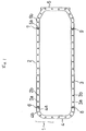
- a split-type gasket 1 consists of two straight gasket sections 2 and 3 and two U-shaped curved gasket sections 4 and 5, all provided with bolt holes 2a, 2b, etc., 3a, 3b, etc., 4a, 4b, etc. and 5a, 5b, etc.
- the straight sections 2 and 3 and curved sections 4 and 5 are connected together at joints 6 to 9.
- Figs. 2 and 3 show the joints.
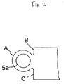
- a protruding portion A has a circular boundary concentric with bolt hole 5a therein and merges smoothly with laterally extending straight edges B and C by way of small circular arcs.
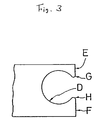
- a recess D has a boundary which is again circular so as closely to receive protruding portion A, and straight laterally extending edges E and F which merge smoothly with recess D at projecting points G and H, all complementary to the configuration of the protruding portion A and edges B and C.
- the present invention provides split-type gaskets which are not prone to leak even without liquid gasket application, with low costs of production in terms of both labour and materials, as well as improved yield.
Description
- This invention refers to a split-type gasket, particularly one configured in ring form and made from a soft material, such as an oil pan gasket to be applied to the contact surfaces between a cylinder block and an oil pan in an engine.
- As is well known, a gasket made of a sheet of asbestos containing a soft material, for example, can be punched out in one stroke by means of a punch die. As an antipollution measure, the use of a soft material free from asbestos is desirable, but sheet material of this type is expensive. In order to reduce the cost of a ring-shaped gasket of poor yield, an internal residue which has been punched out in ring form may be reused at times, but with remaining combination problems. Although it is known to form a gasket as a split-type, as illustrated in Fig. 5 of the accompanying drawings, and to apply liquid gasket material to junctions J1 and J2 when assembling it, leaks can easily occur at junction regions where there is a lower contact pressure, which is troublesome and time-consuming.
- Although it is known to connect respective parts of a split-type gasket through a piece which is formed with a bolt hole and is made of a different material, the combination of different materials raises other problems such as selection of gasket material and thickness, control of contact pressure and the clamping force of the bolt, and the like, and the presence of connecting areas on both sides of the piece concerned leaves a problem of numerous possible leakage points.
- It is also known from US-A-3231289 (Carrell) to provide a split-type gasket comprising at least two gasket sections formed with bolt holes and arranged to be interconnected in the same plane at respective joints to form the gasket, in which each of said joints is formed by a protruding portion on one gasket section and a complementary recess in the other gasket section arranged to receive said protruding portion in interlocking fashion.
- According to the present invention, one of the bolt holes of said one gasket section is located in said protruding portion.
- With such an arrangement, in use of the gasket, the respective gasket sections are interconnected in a region of homogeneous gasket material at a bolt, where the high and stable contact pressure provided by the bolt increases the reliability of the interlocking of the gasket sections, and prevents leakage.
- The protruding portion preferably has a circular outside edge concentric with said bolt hole, and the said recess has a complementary circular inside edge. Preferably the said circular outside edge of the said protruding portion merges smoothly at its inner ends into respective straight edges of said one gasket section which extend laterally outwardly, and the said circular inside edge of the said recess merges smoothly with complementary laterally extending straight edges of the said other gasket section.
- Some embodiments of the invention will now be described by way of example and with reference to the accompanying drawings, in which:-
- Fig. 1 is a plan view of a first embodiment of a split-type gasket according to the invention;
- Fig. 2 is a plan view of one section of a joint in the embodiment of Fig. 1;
- Fig. 3 is a plan view of the other section of the joint;
- Fig. 4 is a plan view of another embodiment of a joint; and
- Fig. 5 is a plan view of a known gasket.
- As illustrated in Fig. 1, a split-type gasket 1 consists of two
straight gasket sections curved gasket sections 4 and 5, all provided withbolt holes straight sections curved sections 4 and 5 are connected together at joints 6 to 9. - Figs. 2 and 3 show the joints. In the joint section of Fig. 2, a protruding portion A has a circular boundary concentric with
bolt hole 5a therein and merges smoothly with laterally extending straight edges B and C by way of small circular arcs. In the joint section of Fig. 3, a recess D has a boundary which is again circular so as closely to receive protruding portion A, and straight laterally extending edges E and F which merge smoothly with recess D at projecting points G and H, all complementary to the configuration of the protruding portion A and edges B and C. - Thus, when the set of
gasket sections 2 to 5 is assembled in a common plane on a mounting surface with joints 6 to 9 interconnected, and bolts are inserted through the various bolt holes, no separation of the gasket sections at joints 6 to 9 can take place. Furthermore, as all of the gasket sections may be formed of homogeneous material, the contact pressure is stabilised and no leaks will occur. - If the dimensions W1 or W2, as illustrated in Fig. 4, would otherwise be so narrow that leakage might occur, then one or both sides of the respective bolt hole, as illustrated with chain lines K and K, may be extended laterally as a circular arc.
- It will thus be understood that the present invention, at least in its preferred forms, provides split-type gaskets which are not prone to leak even without liquid gasket application, with low costs of production in terms of both labour and materials, as well as improved yield.
Claims (3)
- A split-type gasket (1) comprising at least two gasket sections (2,3,4,5) formed with bolt holes (2a,2b, 3a,3b,4a,4b,5a,5b) and arranged to be interconnected in the same plane at respective joints (6,7,8,9) to form the gasket, in which each of said joints is formed by a protruding portion (A) on one gasket section and a complementary recess (D) in the other gasket section arranged to receive said protruding portion in interlocking fashion; characterised in that one of the bolt holes of said one gasket section is located in the said protruding portion (A).
- A gasket as claimed in claim 1, wherein said protruding portion (A) has a circular outside edge concentric with said bolt hole, and the said recess (D) has a complementary circular inside edge.
- A gasket as claimed in claim 2, wherein the said circular outside edge of the said protruding portion merges smoothly at its inner ends into respective straight edges (B,C) of said one gasket section which extend laterally outwardly, and the said circular inside edge of the said recess (D) merges smoothly with complementary laterally extending straight edges (E,F) of the said other gasket section.
Priority Applications (1)
| Application Number | Priority Date | Filing Date | Title |
|---|---|---|---|
| EP95200291A EP0665371B1 (en) | 1991-05-17 | 1992-05-01 | Split-type gasket |
Applications Claiming Priority (4)
| Application Number | Priority Date | Filing Date | Title |
|---|---|---|---|
| JP35003/91 | 1991-05-17 | ||
| JP35001/91U | 1991-05-17 | ||
| JP1991035001U JP2542755Y2 (en) | 1991-05-17 | 1991-05-17 | Structure of connection part of split type gasket |
| JP1991035003U JPH07775Y2 (en) | 1991-05-17 | 1991-05-17 | Split type gasket |
Related Child Applications (2)
| Application Number | Title | Priority Date | Filing Date |
|---|---|---|---|
| EP95200291.3 Division-Into | 1992-05-01 | ||
| EP95200291A Division EP0665371B1 (en) | 1991-05-17 | 1992-05-01 | Split-type gasket |
Publications (2)
| Publication Number | Publication Date |
|---|---|
| EP0514052A1 EP0514052A1 (en) | 1992-11-19 |
| EP0514052B1 true EP0514052B1 (en) | 1995-09-27 |
Family
ID=26373884
Family Applications (2)
| Application Number | Title | Priority Date | Filing Date |
|---|---|---|---|
| EP95200291A Revoked EP0665371B1 (en) | 1991-05-17 | 1992-05-01 | Split-type gasket |
| EP92303975A Revoked EP0514052B1 (en) | 1991-05-17 | 1992-05-01 | Split-type gasket |
Family Applications Before (1)
| Application Number | Title | Priority Date | Filing Date |
|---|---|---|---|
| EP95200291A Revoked EP0665371B1 (en) | 1991-05-17 | 1992-05-01 | Split-type gasket |
Country Status (5)
| Country | Link |
|---|---|
| US (1) | US5236203A (en) |
| EP (2) | EP0665371B1 (en) |
| AU (1) | AU660458B2 (en) |
| DE (2) | DE69205061T2 (en) |
| ES (2) | ES2119302T3 (en) |
Cited By (1)
| Publication number | Priority date | Publication date | Assignee | Title |
|---|---|---|---|---|
| DE19709048A1 (en) * | 1997-03-06 | 1998-09-24 | Mtu Friedrichshafen Gmbh | Seal arrangement for use between e.g. oil sump and crankcase of vehicle engine |
Families Citing this family (19)
| Publication number | Priority date | Publication date | Assignee | Title |
|---|---|---|---|---|
| JP2566529B2 (en) * | 1994-01-31 | 1996-12-25 | 日本ピラー工業株式会社 | Sheet gasket |
| US5618047A (en) * | 1995-03-14 | 1997-04-08 | Dana Corporation | Molded gasket with a multiple component reinforcing element |
| DE19630152C1 (en) * | 1996-07-25 | 1997-05-15 | Gloeckler Dichtsysteme Guenter | Positive connection for long seal in internal combustion engines |
| DE19739196C2 (en) * | 1997-09-08 | 1999-12-30 | Freudenberg Carl Fa | Carrier of a flat gasket |
| US6553664B1 (en) | 1999-12-17 | 2003-04-29 | Parker-Hannifin Corporation | Method of making a segmented gasket having a continuous seal member |
| US6460859B1 (en) * | 2000-04-12 | 2002-10-08 | Parker-Hannifin Corporation | Resilient elastomer and metal retainer gasket for sealing between curved surfaces |
| US6651989B2 (en) | 2001-03-28 | 2003-11-25 | Daana Corporation | Field-adjustable gasket kit |
| US20070170658A1 (en) * | 2006-01-20 | 2007-07-26 | Wilkinson Mark R | Stuffing box bushing, assembly and method of manufacture |
| DE102006017377A1 (en) * | 2006-04-11 | 2007-11-08 | Rolls-Royce Deutschland Ltd & Co Kg | Flap seal for a turbomachine |
| JP2008115908A (en) * | 2006-11-01 | 2008-05-22 | Toyota Motor Corp | Backup ring and tank having the backup ring |
| DE102007009807A1 (en) * | 2007-02-28 | 2008-09-04 | Man Nutzfahrzeuge Ag | Multi-part flat gasket |
| CN101938181B (en) * | 2009-06-29 | 2013-01-02 | 日本电产株式会社 | Motor |
| WO2014139001A1 (en) | 2013-03-15 | 2014-09-18 | Dana Canada Corporation | Heat exchanger with jointed frame |
| US20150369110A1 (en) * | 2014-06-23 | 2015-12-24 | Caterpillar Inc. | Serviceable Soft Gaskets for Durable Heat Shielding |
| US20140319782A1 (en) * | 2014-07-08 | 2014-10-30 | Caterpillar Inc. | Sealing system |
| US10612657B2 (en) * | 2015-09-14 | 2020-04-07 | Caterpillar Inc. | Space plate with seal for joint assembly |
| DE102018204085A1 (en) | 2018-03-16 | 2019-09-19 | Elringklinger Ag | Sealing arrangement, battery or control box, motor vehicle and method for producing a seal assembly |
| US11306821B2 (en) | 2018-07-16 | 2022-04-19 | Wesley G. Moulton | Gasket assembly |
| DE102019213614A1 (en) * | 2019-09-06 | 2021-03-11 | Elringklinger Ag | Sealing arrangement, battery or control box, motor vehicle and method for producing a sealing arrangement |
Family Cites Families (18)
| Publication number | Priority date | Publication date | Assignee | Title |
|---|---|---|---|---|
| GB189315077A (en) * | 1893-08-05 | 1893-09-09 | William Whyte | Improvements in Metallic Packing for Stream and other Engines. |
| US1502524A (en) * | 1919-10-25 | 1924-07-22 | Jr Joseph W Price | Piston-rod packing |
| US1986465A (en) * | 1933-12-20 | 1935-01-01 | Westinghouse Air Brake Co | Gasket construction |
| GB466375A (en) * | 1935-05-22 | 1937-05-27 | Crown Cork & Seal Co | Improvements in or relating to compositions for sealing and gasket purposes |
| US2768036A (en) * | 1955-11-14 | 1956-10-23 | Cleveland Pneumatic Tool Co | Sectional fluid seal |
| US3231289A (en) * | 1962-01-26 | 1966-01-25 | Parker Hannifin Corp | Sealing gasket |
| US3175832A (en) * | 1963-04-26 | 1965-03-30 | Parker Hannifin Corp | Sealing gasket |
| US3438117A (en) * | 1966-10-25 | 1969-04-15 | American Air Filter Co | Method of making a sealing gasket |
| US3583711A (en) * | 1968-10-25 | 1971-06-08 | American Air Filter Co | Collapsible sealing gasket |
| US3738670A (en) * | 1971-09-27 | 1973-06-12 | Parker Hannifin Corp | Sectional gasket |
| US4293135A (en) * | 1980-02-25 | 1981-10-06 | Parker-Hannifin Corporation | Segmented seal |
| US4580793A (en) * | 1984-07-26 | 1986-04-08 | Bronson & Bratton | Split rotary seal ring and method for making same |
| GB8422193D0 (en) * | 1984-09-03 | 1984-10-10 | Klinger Ltd Richard | Gaskets |
| IT8434064V0 (en) * | 1984-10-22 | 1984-10-22 | Zanussi Elettrodomestici | GASKET, IN PARTICULAR FOR HOUSEHOLD APPLIANCES. |
| US4572522A (en) * | 1985-05-06 | 1986-02-25 | Felt Products Mfg. Co. | Interlocking sectional gasket assembly and method of making same |
| FR2659122B1 (en) * | 1990-03-02 | 1993-10-22 | Procal | FLAT GASKET. |
| US5149108A (en) * | 1991-02-15 | 1992-09-22 | Great Gasket Concepts, Inc. | Multi-piece gasket joint |
| US5149109A (en) * | 1991-09-18 | 1992-09-22 | Parker-Hannifin Corporation | Interlocking segmented seal |
-
1992
- 1992-04-30 AU AU15913/92A patent/AU660458B2/en not_active Ceased
- 1992-05-01 DE DE69205061T patent/DE69205061T2/en not_active Revoked
- 1992-05-01 EP EP95200291A patent/EP0665371B1/en not_active Revoked
- 1992-05-01 ES ES95200291T patent/ES2119302T3/en not_active Expired - Lifetime
- 1992-05-01 DE DE69226658T patent/DE69226658T2/en not_active Revoked
- 1992-05-01 ES ES92303975T patent/ES2077353T3/en not_active Expired - Lifetime
- 1992-05-01 EP EP92303975A patent/EP0514052B1/en not_active Revoked
- 1992-05-06 US US07/879,006 patent/US5236203A/en not_active Expired - Fee Related
Cited By (2)
| Publication number | Priority date | Publication date | Assignee | Title |
|---|---|---|---|---|
| DE19709048A1 (en) * | 1997-03-06 | 1998-09-24 | Mtu Friedrichshafen Gmbh | Seal arrangement for use between e.g. oil sump and crankcase of vehicle engine |
| DE19709048C2 (en) * | 1997-03-06 | 1999-04-08 | Mtu Friedrichshafen Gmbh | Sealing arrangement for sealing a first housing against a second housing |
Also Published As
| Publication number | Publication date |
|---|---|
| EP0665371A3 (en) | 1995-08-16 |
| DE69205061D1 (en) | 1995-11-02 |
| ES2119302T3 (en) | 1998-10-01 |
| DE69226658T2 (en) | 1998-12-24 |
| ES2077353T3 (en) | 1995-11-16 |
| US5236203A (en) | 1993-08-17 |
| AU1591392A (en) | 1992-11-19 |
| EP0514052A1 (en) | 1992-11-19 |
| EP0665371A2 (en) | 1995-08-02 |
| DE69205061T2 (en) | 1996-02-29 |
| DE69226658D1 (en) | 1998-09-17 |
| AU660458B2 (en) | 1995-06-29 |
| EP0665371B1 (en) | 1998-08-12 |
Similar Documents
| Publication | Publication Date | Title |
|---|---|---|
| EP0514052B1 (en) | Split-type gasket | |
| US4759556A (en) | Metal gasket with auxiliary bead | |
| US4776073A (en) | Method of manufacturing a steel laminate gasket | |
| EP1021668B1 (en) | Manufacture of gaskets | |
| KR101373624B1 (en) | Static gasket | |
| US5230521A (en) | Metallic laminate gasket with plates of different bead widths fixed together | |
| US6173966B1 (en) | T-joint gasket assembly | |
| US6305695B1 (en) | Gaskets | |
| EP0892199A3 (en) | Metal laminate gasket with wide and narrow flange portions | |
| EP0965778B1 (en) | Metal gasket with two half beads | |
| EP1217268A2 (en) | Metal laminate gasket with continuous bead | |
| KR100226524B1 (en) | Cylinder head gasket | |
| EP1098113A2 (en) | Metal cylinder head gasket with compressibility adjusting slits | |
| EP1182385A2 (en) | Gaskets | |
| US5272808A (en) | Method of manufacturing a cylinder head gasket | |
| US5295699A (en) | Metal laminate gasket with inner projection connecting mechanisms | |
| EP1197688B1 (en) | Metal laminate gasket with bore ring and engaging members thereof | |
| JPH07775Y2 (en) | Split type gasket | |
| JP3965537B2 (en) | Cylinder head gasket | |
| US5895055A (en) | Metal gasket with opposite flanges | |
| GB2097070A (en) | Seal and seal assembly for an engine | |
| JP3606470B2 (en) | Assembly method of split gasket | |
| JP4826935B2 (en) | Metal gasket | |
| GB2092240A (en) | Gasket | |
| JP2542755Y2 (en) | Structure of connection part of split type gasket |
Legal Events
| Date | Code | Title | Description |
|---|---|---|---|
| PUAI | Public reference made under article 153(3) epc to a published international application that has entered the european phase |
Free format text: ORIGINAL CODE: 0009012 |
|
| AK | Designated contracting states |
Kind code of ref document: A1 Designated state(s): CH DE ES FR GB IT LI NL |
|
| 17P | Request for examination filed |
Effective date: 19921102 |
|
| 17Q | First examination report despatched |
Effective date: 19940301 |
|
| GRAA | (expected) grant |
Free format text: ORIGINAL CODE: 0009210 |
|
| AK | Designated contracting states |
Kind code of ref document: B1 Designated state(s): CH DE ES FR GB IT LI NL |
|
| XX | Miscellaneous (additional remarks) |
Free format text: TEILANMELDUNG 95200291.3 EINGEREICHT AM 01/05/92. |
|
| REF | Corresponds to: |
Ref document number: 69205061 Country of ref document: DE Date of ref document: 19951102 |
|
| REG | Reference to a national code |
Ref country code: ES Ref legal event code: FG2A Ref document number: 2077353 Country of ref document: ES Kind code of ref document: T3 |
|
| ET | Fr: translation filed | ||
| ITF | It: translation for a ep patent filed |
Owner name: SOCIETA' ITALIANA BREVETTI S.P.A. |
|
| PLAV | Examination of admissibility of opposition |
Free format text: ORIGINAL CODE: EPIDOS OPEX |
|
| PLBQ | Unpublished change to opponent data |
Free format text: ORIGINAL CODE: EPIDOS OPPO |
|
| PLBI | Opposition filed |
Free format text: ORIGINAL CODE: 0009260 |
|
| PLAV | Examination of admissibility of opposition |
Free format text: ORIGINAL CODE: EPIDOS OPEX |
|
| PLBF | Reply of patent proprietor to notice(s) of opposition |
Free format text: ORIGINAL CODE: EPIDOS OBSO |
|
| 26 | Opposition filed |
Opponent name: REINZ-DICHTUNGS-GMBH Effective date: 19960626 |
|
| NLR1 | Nl: opposition has been filed with the epo |
Opponent name: REINZ-DICHTUNGS-GMBH |
|
| PLBF | Reply of patent proprietor to notice(s) of opposition |
Free format text: ORIGINAL CODE: EPIDOS OBSO |
|
| PLBF | Reply of patent proprietor to notice(s) of opposition |
Free format text: ORIGINAL CODE: EPIDOS OBSO |
|
| PGFP | Annual fee paid to national office [announced via postgrant information from national office to epo] |
Ref country code: FR Payment date: 19980415 Year of fee payment: 7 |
|
| PGFP | Annual fee paid to national office [announced via postgrant information from national office to epo] |
Ref country code: CH Payment date: 19980423 Year of fee payment: 7 |
|
| PGFP | Annual fee paid to national office [announced via postgrant information from national office to epo] |
Ref country code: GB Payment date: 19980424 Year of fee payment: 7 |
|
| PGFP | Annual fee paid to national office [announced via postgrant information from national office to epo] |
Ref country code: ES Payment date: 19980513 Year of fee payment: 7 |
|
| PGFP | Annual fee paid to national office [announced via postgrant information from national office to epo] |
Ref country code: NL Payment date: 19980531 Year of fee payment: 7 |
|
| PGFP | Annual fee paid to national office [announced via postgrant information from national office to epo] |
Ref country code: DE Payment date: 19980706 Year of fee payment: 7 |
|
| RDAH | Patent revoked |
Free format text: ORIGINAL CODE: EPIDOS REVO |
|
| RDAG | Patent revoked |
Free format text: ORIGINAL CODE: 0009271 |
|
| STAA | Information on the status of an ep patent application or granted ep patent |
Free format text: STATUS: PATENT REVOKED |
|
| REG | Reference to a national code |
Ref country code: CH Ref legal event code: PL |
|
| 27W | Patent revoked |
Effective date: 19981007 |
|
| GBPR | Gb: patent revoked under art. 102 of the ep convention designating the uk as contracting state |
Free format text: 981007 |
|
| NLR2 | Nl: decision of opposition |