EP0513951B1 - Werkzeugdrehsicherung - Google Patents
Werkzeugdrehsicherung Download PDFInfo
- Publication number
- EP0513951B1 EP0513951B1 EP92250113A EP92250113A EP0513951B1 EP 0513951 B1 EP0513951 B1 EP 0513951B1 EP 92250113 A EP92250113 A EP 92250113A EP 92250113 A EP92250113 A EP 92250113A EP 0513951 B1 EP0513951 B1 EP 0513951B1
- Authority
- EP
- European Patent Office
- Prior art keywords
- tool
- clamping plate
- injection moulding
- moulding machine
- gripper
- Prior art date
- Legal status (The legal status is an assumption and is not a legal conclusion. Google has not performed a legal analysis and makes no representation as to the accuracy of the status listed.)
- Expired - Lifetime
Links
Images

Classifications
-
- B—PERFORMING OPERATIONS; TRANSPORTING
- B29—WORKING OF PLASTICS; WORKING OF SUBSTANCES IN A PLASTIC STATE IN GENERAL
- B29C—SHAPING OR JOINING OF PLASTICS; SHAPING OF MATERIAL IN A PLASTIC STATE, NOT OTHERWISE PROVIDED FOR; AFTER-TREATMENT OF THE SHAPED PRODUCTS, e.g. REPAIRING
- B29C45/00—Injection moulding, i.e. forcing the required volume of moulding material through a nozzle into a closed mould; Apparatus therefor
- B29C45/17—Component parts, details or accessories; Auxiliary operations
- B29C45/1756—Handling of moulds or mould parts, e.g. mould exchanging means
-
- B—PERFORMING OPERATIONS; TRANSPORTING
- B29—WORKING OF PLASTICS; WORKING OF SUBSTANCES IN A PLASTIC STATE IN GENERAL
- B29C—SHAPING OR JOINING OF PLASTICS; SHAPING OF MATERIAL IN A PLASTIC STATE, NOT OTHERWISE PROVIDED FOR; AFTER-TREATMENT OF THE SHAPED PRODUCTS, e.g. REPAIRING
- B29C49/00—Blow-moulding, i.e. blowing a preform or parison to a desired shape within a mould; Apparatus therefor
- B29C49/42—Component parts, details or accessories; Auxiliary operations
- B29C49/48—Moulds
- B29C2049/4856—Mounting, exchanging or centering moulds or parts thereof
- B29C2049/4858—Exchanging mould parts, e.g. for changing the mould size or geometry for making different products in the same mould
Definitions
- the invention relates to an injection molding machine according to the preamble of claim 1.
- Injection molding machines of this type have mold mounting plates between which a mold block can be clamped.
- the clamping plates are closed or opened when the tool is installed or removed.
- the tool tends to twist or tilt.
- the tool must be inserted between the clamping plates, carefully centered there and held outside the direction of travel without changing the position.
- a safe coupling of the power lines should be carried out with the least effort.
- an injection molding machine is known with an injection mold, which has a tool support plate, which rests with its lower edge on horizontal axis rollers of the tool holder and with one of its lateral edges rests against a lateral stop of the tool holder.
- the disadvantage of this design is the time-consuming and difficult threading of the tool support plate into the guide.
- the relatively complex guide has such a large clearance that it is not possible to prevent the tool from tipping or rotating.
- the invention addresses the problem of being able to carry out a trouble-free, partially or fully automated tool change, in which the tool is held in the desired position in a defined manner in each phase of the change work.
- the tool is inserted with its tool support plate into at least one guide claw.
- This guide claw positively grips the tool support plate and holds it in a defined manner parallel to the clamping plate during the axial movement of the tool. This secure gripping is maintained until centering elements provided on the tool come into engagement with centering holes provided on the machine.
- the positive connection between the guide claw and tool support plate is released, and the The plate can be touched immediately.
- the release of the handle by the guide claw is achieved by a displacement axis inclined with respect to the tool movement direction, on which the guide claw is simultaneously displaced perpendicular to the central axis with the tool movement. Different flank lengths make it easy to detach the contact plate from the guide claw. There is a pure forced operation, so that no control and no end position query is required.
- the geometrical relationships are chosen so that only one degree of freedom is allowed when changing the tool. An overdetermination of the geometric conditions is avoided in that the tool between the clamping plates is taken over by the usually existing centering immediately before the clamping process.
- the simple guide elements which take up little space, can be retrofitted to existing machines.
- the component which can be carried out separately, can be installed on existing injection molding machines without obstructing the other subassemblies, both in machines with horizontal and vertical tool changing devices.
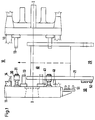
- FIG. 1 shows the insertion of the tool block 20 between the clamping plates 11 and 12 of the injection molding machine.
- the tool 20 is supported from below by the indicated tool support consoles 13.
- a fixedly mounted power supply coupling 50 with built-in coupling nipples 51 is shown on the side of the fixed platen 11. The supply couplings on the movable clamping plate have not been shown.
- the contact plate 21 of the tool block 20 facing the fixed clamping plate 11 is threaded into the guide claws 31 of the gripper 30. This creates a positive connection with the tool block 20 in the direction of the main machine axis or central axis I. Compression springs 33 between the fixed platen 11 and the guide claws 31 hold the latter in a defined insertion position.
- the tool is pushed into the clamping unit 10 up to the stop on the console 14.
- the console 14 is attached to the side of the locking system 10 opposite the insertion side. Centering segments 41 can be seen on the contact plate 21, which have a sufficient distance from the fixed clamping plate 11 during the retraction.
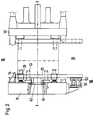
- Fig. 2 shows that during the closing movement of the locking unit 10 between the guide claws 31 and the tool support plate 21 there is at least as long a positive fit until the centering segments 41 on the tool block 20 are immersed in the centering bore 42 of the machine-side platen 11. This prevents an inclination of the tool block 20 with respect to the main machine axis I over the entire phase of the feed movement.
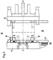
- the tool block 20 is clamped by the clamping plates 11 and 12. After the positive connection between the Guide claw 31 and the tool support plate 21 can be pushed under the shorter flanks 38 of the guide claw 31 to the fixed platen 11. If a plate contact 11, 21 is made on both sides, the tool 20 can be clamped and the tool installation is thus ended.
- the energy supply coupling 50 is coupled in this phase, etc. also positively controlled.
- FIG. 4 shows the fixed platen 11 to which a mounting plate 35 is attached.
- a guide pin 36 is fastened to the mounting plate 35.
- the position of the bolt 36 is chosen so that the bolt axis II to the machine main axis I forms an angle between 10 to 25 degrees, u.z. pointing away from the tool block.
- a slider 37 Arranged around the bolt 36 is a slider 37, which can be moved coaxially to the bolt and is pressed via a compression spring 33 to the head end of the bolt 36.
- a guide claw 31 is provided on the slider 37, the flank 34 of which points away from the clamping plate is longer than the flank 38 facing the clamping plate. On the shorter flank 38 there is an end face 39 arranged parallel to the main machine axis I.
- flanks 34 and 38 have insertion bevels 32 with which the threading of the tool support plate is facilitated.
Landscapes
- Engineering & Computer Science (AREA)
- Manufacturing & Machinery (AREA)
- Mechanical Engineering (AREA)
- Moulds For Moulding Plastics Or The Like (AREA)
Description
- Die Erfindung betrifft eine Spritzgießmaschine nach den Oberbegriff des Anspruchs 1.
- Derartige Spritzgießmaschinen weisen Werkzeugaufspannplatten auf, zwischen denen ein Werkzeugblock klemmbar ist. Beim Ein- bzw. Ausbau des Werkzeugs werden die Aufspannplatten zu- bzw. aufgefahren. Solange keine Plattenberührung vorhanden ist, neigt das Werkzeug dazu, sich zu verdrehen oder zu kippen. Insbesondere beim Einbau muß das Werkzeug zwischen die Aufspannplatten eingeführt werden, dort sorgfältig zentriert und außerhalb der Verfahrrichtung ohne Positionsänderung gehalten werden. Darüber hinaus soll bei geringstem Aufwand ein sicheres Kuppeln der Energieleitungen durchgeführt werden.
- Aus DE-OS 38 36 986 ist eine Spritzgießmaschine bekannt mit einem Spritzwerkzeug, welches eine Werkzeuganlageplatte aufweist, die mit ihrem unteren Rand auf Horizonalachsenrollen der Werkzeugaufnahme aufliegt und mit einem ihrer seitlichen Ränder an einen seitlichen Anschlag der Werkzeugaufnahme anliegt.
- Nachteil dieser Ausführung ist das zeitaufwendige und schwierige Einfädeln der Werkzeuganlageplatte in die Führung. Darüber hinaus weist die relativ aufwendig konstruierte Führung ein so großes Spiel auf, daß ein exaktes Verhindern das Kippens oder Verdrehens des Werkzeugs nicht möglich ist.
- Aus EP A1 0 314 794 sind motorisch betriebene Klemmkeile bekannt, die senkrecht zur Mittenachse bewegbar sind und das Werkzeug an der Anlageplatte angreifen. Die Gleitfläche der Keile bzw. der Anlageplatte weisen in Richtung Aufspannplatte von der Mittenachse weg. Durch Lage und Größe der Flächen ist aber nur ein grobes Zentrieren des Werkzeugblocks möglich.
- Aus der EP-A-0092686 ist eine Werkzeugwechselvorrichtung bekannt,bei der die Adapterplatte mit dem Formwerkzeug durch Einschubführungen sowohl parallel als auch quer zur Einschubrichtung exakt gegen die stationäre Formaufspannplatte zentriert und ausgerichtet wird.
- Die Erfindung widmet sich dem Problem, einen störungsfreien teil- bzw. vollautomatisierten Werkzeugwechsel durchführen zu können, bei dem in jeder Phase der Wechselarbeit das Werkzeug definiert in der gewünschten Lage gehalten wird.
- Gelöst wird diese Aufgabe durch die kennzeichnenden Merkmale des Vorrichtungsanspruchs 1.
- Das Werkzeug wird dabei mit seiner Werkzeuganlageplatte in mindestens einer Führungsklaue eingeführt. Diese Führungsklaue greift die Werkzeuganlageplatte formschlüssig und hält sie definiert parallel zur Aufspannplatte während der axialen Bewegung des Werkzeugs. Dieses sichere Greifen wird solange aufrechterhalten, bis am Werkzeug vorgesehene Zentrierelemente mit an der Maschine vorgesehenen Zentrierbohrungen in Eingriff kommen. Der Formschluß zwischen der Führungsklaue und Werkzeuganlageplatte wird aufgehoben, und die Plattenberührung kann unmittelbar erfolgen. Das Lösen des Griffes durch die Führungsklaue wird erreicht durch eine gegenüber der Werkzeugbewegungsrichtung geneigte Verschiebeachse, auf der die Führungsklaue mit der Werkzeugbewegung gleichzeitig senkrecht zur Mittenachse verschoben wird. Durch unterschiedliche Flankenlängen ist ein Lösen der Anlageplatte von der Führungsklaue in einfacher Weise möglich. Es liegt eine reine Zwangsführung vor, so daß keine Ansteuerung und keine Endlagenabfrage erforderlich ist.
- Ein weiterer Vorteil ist darin zu sehen, daß die Energieversorgungskupplungen zwangsgesteuert miteinander gekoppelt werden. Hierdurch ist ein verschleißarmes und dabei sicheres Kuppeln möglich.
- Die geometrischen verhältnisse sind jeweils so gewählt, daß beim Wechsel des Werkzeugs immer nur ein Freiheitsgrad zugelassen wird. Eine Überbestimmung der geometrischen verhältnisse wird dadurch vermieden, daß unmittelbar vor dem Klemmvorgang das Werkzeug zwischen den Aufspannplatten die Führung des Werkzeugblocks von der üblicherweise vorhandenen Zentrierung übernommen wird.
- Die einfachen und dabei wenig Bauraum einnehmenden Führungselemente lassen sich bei vorhandenen Maschinen nachrüsten. Das separat ausführbare Bauteil läßt sich ohne Behinderung der übrigen Baugruppen an vorhandenen Spritzgießmaschien einbauen, u.z. sowohl bei Maschinen mit horizontalen wie auch vertikalen Werkzeugwechseleinrichtungen.
- Ein Beispiel der Erfindung ist in der Zeichnung dargelegt. Dabei zeigen:
- Fig. 1 die Werkzeugwechseleinrichtung in geöffnetem Zustand,
- Fig. 2 die Werkzeugwechseleinrichtung während des Zufahrens,
- Fig. 3 die Werkzeugwechseleinrichtung in eingebautem Zustand,
- Fig. 4 einen Greifer.
- In den Fig. 1 und 3 ist ein waagerechter Werkzeugeinbau in die Spritzgießmaschine dargestellt, der von beiden Seiten her möglich ist. Zu sehen ist jeweils die Draufsicht auf das Werkzeug und die Schließeinheit der Spritzgießmaschine.
- Entsprechendes gilt für einen Vertikalwerkzeugein- sowie -ausbau.
- Die Fig. 1 zeigt den Einschub des Werkzeugblocks 20 zwischen die Aufspannplatten 11 und 12 der Spritzgießmaschine. Innerhalb der Schließeinheit 10 wird das Werkzeug 20 von unten durch die angedeuteten Werkzeugauflagekonsolen 13 abgestützt. Seitlich an der festen Aufspannplatte 11 ist eine fest montierte Energieversorgungskupplung 50 mit eingebauten Kupplungsnippeln 51 dargestellt. Auf eine Darstellung der Versorgungskupplungen an der beweglichen Ausspannplatte wurde verzichtet.
- Beim Einfahren des Werkzeugblockes ist von der festen und der beweglichen Aufspannplatte 11 und 12 gerade ein solcher Einfahrabstand einzuhalten, bei dem die Kupplungsnippel 51 beim Einfahren nicht mit den Gegenstücken 52 am Werkzeugblock kollidieren.
- Während des Werkzeugeinschubs wird die der festen Aufspannplatte 11 zugewandte Anlageplatte 21 des Werkzeugblocks 20 in die Führungsklauen 31 des Greifers 30 eingefädelt. Hiermit wird ein Formschluß mit dem Werkzeugblock 20 in Richtung der Maschinennauptachse oder Mittenachse I hergestellt. Druckfedern 33 zwischen der festen Aufspannplatte 11 und den Führungsklauen 31 halten letztere dabei in definierter Einschubposition.
- Das Werkzeug wird bis auf Anschlag an der Konsole 14 in die Schließeinheit 10 eingeschoben. Die Konsole 14 ist an der der Einschubseite gegenüberliegenden Seite der Schließanlage 10 angebracht. An der Anlageplatte 21 sind Zentriersegmente 41 zu erkennen, die während des Einfahrens einen ausreichenden Abstand zur festen Aufspannplatte 11 aufweisen.
- Fig. 2 zeigt, daß während der Zufahrbewegung der Schließeinheit 10 zwischen den Führungsklauen 31 und der Werkzeuganlageplatte 21 mindestens so lange Formschluß besteht, bis die Zentriersegmente 41 am Werkzeugblock 20 in die Zentrierbohrung 42 der maschinenseitigen Aufspannplatte 11 eingetaucht sind. Eine Schrägstellung des Werkzeugblocks 20 bezüglich der Maschinenhauptachse I über die gesamte Phase Zufahrbewegung wird hiermit verhindert.
- Erst nach Eintauchen der Zentriersegmente 41 wird der Formschluß zwischen den Führungsklauen 31 und der Werkzeuganlageplatte 21 aufgehoben. Dies geschieht zwangsgesteuert aufgrund geneigter Bewegungsachse. Der Werkzeugblock 20 ruht aufgrund seines Gewichtes sicher auf den Auflagekonsolen 13.
- In der Fig. 3 wird der Werkzeugblock 20 durch die Aufspannplatten 11 und 12 geklemmt. Nach Aufhebung des Formschlusses zwischen der Führungsklaue 31 und der Werkzeuganlageplatte 21 kann diese unter die kürzeren Flanken 38 der Führungsklaue 31 hindurch an die feste Aufspannplatte 11 geschoben werden. Ist eine beiderseitige Plattenberührung 11, 21 hergestellt, kann das Werkzeug 20 gespannt werden, und der Werkzeugeinbau ist somit beendet.
- Die Energieversorgungskupplung 50 wird in dieser Phase gekuppelt, u.z. ebenfalls zwangsgesteuert.
- Das Detailbild der Fig. 4 zeigt die feste Aufspannplatte 11, an der eine Montageplatte 35 befestigt ist. An der Montageplatte 35 ist ein Führungsbolzen 36 befestigt. Die lage des Bolzens 36 ist so gewählt, daß die Bolzenachse II zur Maschinenhauptachse I einen Winkel zwischen 10 bis 25 Grad bildet, u.z. von dem Werkzeugblock wegweisend. Den Bolzen 36 umgreifend ist ein Gleitstück 37 angeordnet, das koaxial zum Bolzen bewegbar ist und über eine Druckfeder 33 zum kopfseitigen Ende des Bolzens 36 gedrückt wird.
- An dem Gleitstück 37 ist eine Führungsklaue 31 vorgesehen, deren von der Aufspannplatte wegweisende Flanke 34 länger ist als die zur Spannplatte weisende Flanke 38. An der kürzeren Flanke 38 befindet sich eine parallel zur Maschinenhauptachse I angeordnete Stirnfläche 39.
- Die Flanken 34 und 38 weisen Einführungsschrägen 32 auf, mit denen das Einfädeln der Werkzeuganlageplatte erleichtert wird.
-
- 10
- Schließeinheit
- 11
- feste Aufspannplatte
- 12
- bewegliche Aufspannplatte
- 13
- Auflagekonsole
- 14
- Konsole
- 20
- Werkzeugblock
- 21
- Anlageplatte
- 30
- Greifer
- 31
- Führungsklaue
- 32
- Einführschrägen
- 33
- Druckfeder
- 34
- lange Flanke
- 35
- Montageplatte
- 36
- Führungsbolzen
- 37
- Gleitstück
- 38
- kurze Flanke
- 39
- Stirnfläche
- 40
- Zentrierung
- 41
- Zentriersegment
- 42
- Zentrierbohrung
- 50
- Kupplung
- 51
- Nippel
- 52
- Nippelgegenstück
- I
- Maschinenhauptachse
- II
- Bolzenachse
Claims (5)
- Spritzgießmaschine mit beweglicher und fester Aufspannplatte, zwischen denen ein Werkzeuganlageplatten aufweisender Werkzeugblock zentriert einspannbar und wechselbar ist,
dadurch gekennzeichnet,
daß an der festen Aufspannplatte (11) mindestens ein Greifer (30) vorgesehen ist, der eine Führungsklaue (31) aufweist, die den Rand der Anlageplatte (21) des Werkzeugblocks (20) umgreift, und deren zur Aufspannplatte (11) zugewandte Flanke (38) im Vergleich zur abgewandten Flanke (34) kürzer ist und daß der Greifer (30) durch mechanische Mittel (36) in einer Richtung bewegbar ist, die linear im wesentlichen in Richtung fester Aufspannplatte (11) und von der Mittenachse I wegweist. - Spritzgießmaschine nach Anspruch 1,
dadurch gekennzeichnet,
daß an der kürzeren Flanke (38) des Greifers (30) eine senkrecht zur Außenseite der festen Aufspannplatte (11) angeordnete eine Gleitreibung zulassende Stirnflächen (39) vorgesehen ist. - Spritzgießmaschine nach Anspruch 2,
dadurch gekennzeichnet,
daß die Mündung der Führungsklaue (31) Einführungsschrägen (32) aufweist. - Spritzgießmaschine nach den Ansprüchen 2 und 3,
dadurch gekennzeichnet,
daß die Führungsklaue (31) an einem Gleitstück (37) angeordnet ist, durch welches gleitend ein Bolzen (36) führbar ist. - Spritzgießmaschine nach Anspruch 4,
dadurch gekennzeichnet,
daß der Führungsbolzen (36) in einem Winkel von 10 bis 25 Grad zur Mittenachse 1 hin angeordnet ist.
Applications Claiming Priority (3)
| Application Number | Priority Date | Filing Date | Title |
|---|---|---|---|
| DE4115957 | 1991-05-13 | ||
| DE4115957A DE4115957C2 (de) | 1991-05-13 | 1991-05-13 | Spritzgießmaschine |
| US07/882,326 US5302105A (en) | 1991-05-13 | 1992-05-13 | Method for replacing a mold block in an injection molding machine |
Publications (3)
| Publication Number | Publication Date |
|---|---|
| EP0513951A2 EP0513951A2 (de) | 1992-11-19 |
| EP0513951A3 EP0513951A3 (en) | 1993-02-17 |
| EP0513951B1 true EP0513951B1 (de) | 1996-06-12 |
Family
ID=25903657
Family Applications (1)
| Application Number | Title | Priority Date | Filing Date |
|---|---|---|---|
| EP92250113A Expired - Lifetime EP0513951B1 (de) | 1991-05-13 | 1992-05-08 | Werkzeugdrehsicherung |
Country Status (3)
| Country | Link |
|---|---|
| US (1) | US5302105A (de) |
| EP (1) | EP0513951B1 (de) |
| DE (1) | DE4115957C2 (de) |
Families Citing this family (12)
| Publication number | Priority date | Publication date | Assignee | Title |
|---|---|---|---|---|
| DE19518480C2 (de) * | 1995-05-19 | 1997-07-17 | Krauss Maffei Ag | Vorrichtung zum Zentrieren der Werkzeuge für Spritzgießmaschinen |
| JP2005104071A (ja) * | 2003-10-01 | 2005-04-21 | Toyota Motor Corp | 成形装置および専用型の段替方法 |
| US7393197B2 (en) * | 2003-10-14 | 2008-07-01 | Incoe Corporation | Injection molding machine having a side-injection sub-assembly and a method for accessing a hot passage distributor system contained therein |
| US20060051445A1 (en) * | 2004-09-03 | 2006-03-09 | Sten Rundberg | Injection molding system, apparatus, method and quick-connect mechanism |
| JP4885475B2 (ja) * | 2005-05-13 | 2012-02-29 | 東芝機械株式会社 | ダイカストマシン等の型締装置及び同型締装置を備えた金型交換方法ならびに移動側ダイプレートの交換システム |
| CN101204800A (zh) * | 2006-12-22 | 2008-06-25 | 鸿富锦精密工业(深圳)有限公司 | 模具镶块拆卸装置 |
| MX2012002242A (es) | 2009-09-07 | 2012-04-11 | Sidel Participations | Metodo para cambiar un molde. |
| FR2949708B1 (fr) * | 2009-09-07 | 2017-01-13 | Sidel Participations | Procede de changement d'un moule pour la fabrication de recipients et dispositifs de fixation pour la mise en oeuvre d'un tel procede |
| DE102013113077A1 (de) | 2013-11-26 | 2015-05-28 | Krones Ag | Blasformmaschine mit Blasformwechselroboter mit zusätzlicher Behandlungsfunktion |
| DE102013113074A1 (de) * | 2013-11-26 | 2015-05-28 | Krones Ag | Blasformmaschine mit Wechselroboter und Greifeinrichtung und Verfahren zu deren Betrieb |
| DE102013113076A1 (de) | 2013-11-26 | 2015-05-28 | Krones Ag | Blasformmaschine mit Wechselroboter und Verfahren zu deren Betrieb |
| JP6441271B2 (ja) * | 2016-08-23 | 2018-12-19 | 株式会社名機製作所 | 金型回転式射出成形機および金型回転式射出成形機の金型交換方法 |
Family Cites Families (6)
| Publication number | Priority date | Publication date | Assignee | Title |
|---|---|---|---|---|
| DE3215567C2 (de) * | 1982-04-26 | 1996-07-11 | Battenfeld Gmbh | Schnellwechsel- und/oder Spannvorrichtung für die Formwerkzeuge von Druck- oder Spritzgießmaschinen |
| DE3508867C1 (de) * | 1985-03-13 | 1986-11-13 | Karl 7298 Loßburg Hehl | Horizontale Formschliesseinheit einer Kunststoff-Spritzgiessmaschine |
| US4529371A (en) * | 1984-06-06 | 1985-07-16 | Cincinnati Milacron Inc. | Mold changer for a press preferably an injection molding machine |
| DE3501000A1 (de) * | 1984-12-06 | 1986-06-12 | Mannesmann Demag Kunststofftechnik Zweigniederlassung der Mannesmann Demag AG, 8501 Schwaig | Werkzeug-einbau- und spannvorrichtung an einer spritzgiessmaschine |
| DE3836986C2 (de) * | 1988-10-31 | 1994-07-14 | Boy Gmbh Dr | Spritzgießmaschine mit Spritzwerkzeugzentriervorrichtung |
| US5096404A (en) * | 1990-10-31 | 1992-03-17 | At&T Bell Laboratories | Quick mold change arrangement for injection molding machines |
-
1991
- 1991-05-13 DE DE4115957A patent/DE4115957C2/de not_active Expired - Fee Related
-
1992
- 1992-05-08 EP EP92250113A patent/EP0513951B1/de not_active Expired - Lifetime
- 1992-05-13 US US07/882,326 patent/US5302105A/en not_active Expired - Fee Related
Also Published As
| Publication number | Publication date |
|---|---|
| DE4115957C2 (de) | 1995-06-14 |
| US5302105A (en) | 1994-04-12 |
| EP0513951A2 (de) | 1992-11-19 |
| EP0513951A3 (en) | 1993-02-17 |
| DE4115957A1 (de) | 1992-11-19 |
Similar Documents
| Publication | Publication Date | Title |
|---|---|---|
| EP0092686B1 (de) | Schnellwechsel- und/oder Spannvorrichtung für die Formwerkzeuge von Spritzgiessmaschinen | |
| EP0092685B1 (de) | Schnellwechsel- und/oder Spannvorrichtung für die Formwerkzeuge von Spritzgiessmaschinen | |
| EP0519438B1 (de) | Schnellspannvorrichtung | |
| EP0530577B1 (de) | Vorrichtung zur Positionierung eines dem automatischen Druckplattenwechsel dienenden Magazins | |
| DE69003417T2 (de) | Haltevorrichtung für ein längliches Werkstück, wie ein Stempel, eine Matrize oder ein ähnliches Werkzeug auf einem Werktisch einer Abkantpresse. | |
| DE4036915C2 (de) | ||
| DE4115957C2 (de) | Spritzgießmaschine | |
| EP0184744B1 (de) | Werkzeug, insbesondere Spritzgiessform | |
| DE3501000C2 (de) | ||
| DE102018101602A1 (de) | Zuhaltung und Sicherheitseinrichtung mit geringen Abmessungen | |
| DE3929717A1 (de) | Befestigungsvorrichtung fuer werkzeuge an einem werkzeugtraeger | |
| EP3502356B1 (de) | Schnellwechsler, adapter und schnellwechselsystem | |
| EP0195184B1 (de) | Spannbackenwechselvorrichtung | |
| DE4428247B4 (de) | Transportvorrichtung für textile Packungen | |
| EP0118587B1 (de) | Werkzeugmaschine mit einer Anzahl von Bearbeitungsspindeln | |
| EP0157353B1 (de) | Fördervorrichtung | |
| DE3438957C2 (de) | ||
| DE3138495A1 (de) | Spuleneinsetzgeraet | |
| WO1992002671A1 (de) | Flachstrickmaschine | |
| DE3710297C2 (de) | ||
| EP0175673B1 (de) | Vorrichtung zum Wechseln der Werkstück-Spanneinrichtung eines Greiferkopfes | |
| DE69416395T2 (de) | Methode und Einrichtung zur Bürstenherstellung | |
| DE4138186C1 (de) | ||
| EP0004381B1 (de) | Container-Befestigungsvorrichtung | |
| DE202004016066U1 (de) | Spritzgießmaschine |
Legal Events
| Date | Code | Title | Description |
|---|---|---|---|
| PUAI | Public reference made under article 153(3) epc to a published international application that has entered the european phase |
Free format text: ORIGINAL CODE: 0009012 |
|
| AK | Designated contracting states |
Kind code of ref document: A2 Designated state(s): AT BE CH DE ES FR GB IT LI NL |
|
| PUAL | Search report despatched |
Free format text: ORIGINAL CODE: 0009013 |
|
| AK | Designated contracting states |
Kind code of ref document: A3 Designated state(s): AT BE CH DE ES FR GB IT LI NL |
|
| 17P | Request for examination filed |
Effective date: 19930317 |
|
| 17Q | First examination report despatched |
Effective date: 19940729 |
|
| GRAH | Despatch of communication of intention to grant a patent |
Free format text: ORIGINAL CODE: EPIDOS IGRA |
|
| GRAH | Despatch of communication of intention to grant a patent |
Free format text: ORIGINAL CODE: EPIDOS IGRA |
|
| GRAA | (expected) grant |
Free format text: ORIGINAL CODE: 0009210 |
|
| ITF | It: translation for a ep patent filed | ||
| AK | Designated contracting states |
Kind code of ref document: B1 Designated state(s): AT BE CH DE ES FR GB IT LI NL |
|
| REF | Corresponds to: |
Ref document number: 139175 Country of ref document: AT Date of ref document: 19960615 Kind code of ref document: T |
|
| REG | Reference to a national code |
Ref country code: CH Ref legal event code: NV Representative=s name: E. BLUM & CO. PATENTANWAELTE |
|
| ET | Fr: translation filed | ||
| REF | Corresponds to: |
Ref document number: 59206528 Country of ref document: DE Date of ref document: 19960718 |
|
| GBT | Gb: translation of ep patent filed (gb section 77(6)(a)/1977) |
Effective date: 19960802 |
|
| PG25 | Lapsed in a contracting state [announced via postgrant information from national office to epo] |
Ref country code: ES Free format text: LAPSE BECAUSE OF FAILURE TO SUBMIT A TRANSLATION OF THE DESCRIPTION OR TO PAY THE FEE WITHIN THE PRESCRIBED TIME-LIMIT Effective date: 19960923 |
|
| PGFP | Annual fee paid to national office [announced via postgrant information from national office to epo] |
Ref country code: FR Payment date: 19970411 Year of fee payment: 6 |
|
| PGFP | Annual fee paid to national office [announced via postgrant information from national office to epo] |
Ref country code: BE Payment date: 19970417 Year of fee payment: 6 |
|
| PLBE | No opposition filed within time limit |
Free format text: ORIGINAL CODE: 0009261 |
|
| PGFP | Annual fee paid to national office [announced via postgrant information from national office to epo] |
Ref country code: AT Payment date: 19970422 Year of fee payment: 6 |
|
| PGFP | Annual fee paid to national office [announced via postgrant information from national office to epo] |
Ref country code: NL Payment date: 19970428 Year of fee payment: 6 |
|
| PGFP | Annual fee paid to national office [announced via postgrant information from national office to epo] |
Ref country code: CH Payment date: 19970430 Year of fee payment: 6 |
|
| PGFP | Annual fee paid to national office [announced via postgrant information from national office to epo] |
Ref country code: ES Payment date: 19970519 Year of fee payment: 6 |
|
| 26N | No opposition filed | ||
| PGFP | Annual fee paid to national office [announced via postgrant information from national office to epo] |
Ref country code: GB Payment date: 19970915 Year of fee payment: 6 |
|
| PG25 | Lapsed in a contracting state [announced via postgrant information from national office to epo] |
Ref country code: GB Free format text: LAPSE BECAUSE OF NON-PAYMENT OF DUE FEES Effective date: 19980508 Ref country code: AT Free format text: LAPSE BECAUSE OF NON-PAYMENT OF DUE FEES Effective date: 19980508 |
|
| PG25 | Lapsed in a contracting state [announced via postgrant information from national office to epo] |
Ref country code: LI Free format text: LAPSE BECAUSE OF NON-PAYMENT OF DUE FEES Effective date: 19980531 Ref country code: FR Free format text: LAPSE BECAUSE OF NON-PAYMENT OF DUE FEES Effective date: 19980531 Ref country code: CH Free format text: LAPSE BECAUSE OF NON-PAYMENT OF DUE FEES Effective date: 19980531 Ref country code: BE Free format text: LAPSE BECAUSE OF NON-PAYMENT OF DUE FEES Effective date: 19980531 |
|
| BERE | Be: lapsed |
Owner name: MANNESMANN A.G. Effective date: 19980531 |
|
| PG25 | Lapsed in a contracting state [announced via postgrant information from national office to epo] |
Ref country code: NL Free format text: LAPSE BECAUSE OF NON-PAYMENT OF DUE FEES Effective date: 19981201 |
|
| GBPC | Gb: european patent ceased through non-payment of renewal fee |
Effective date: 19980508 |
|
| REG | Reference to a national code |
Ref country code: CH Ref legal event code: PL |
|
| NLV4 | Nl: lapsed or anulled due to non-payment of the annual fee |
Effective date: 19981201 |
|
| REG | Reference to a national code |
Ref country code: FR Ref legal event code: ST |
|
| PGFP | Annual fee paid to national office [announced via postgrant information from national office to epo] |
Ref country code: DE Payment date: 20030514 Year of fee payment: 12 |
|
| PG25 | Lapsed in a contracting state [announced via postgrant information from national office to epo] |
Ref country code: DE Free format text: LAPSE BECAUSE OF NON-PAYMENT OF DUE FEES Effective date: 20041201 |
|
| PG25 | Lapsed in a contracting state [announced via postgrant information from national office to epo] |
Ref country code: IT Free format text: LAPSE BECAUSE OF NON-PAYMENT OF DUE FEES Effective date: 20050508 |