EP0513793B1 - Evaporator for freezing water into ice cubes and method for manufacturing such an evaporator - Google Patents
Evaporator for freezing water into ice cubes and method for manufacturing such an evaporator Download PDFInfo
- Publication number
- EP0513793B1 EP0513793B1 EP92108164A EP92108164A EP0513793B1 EP 0513793 B1 EP0513793 B1 EP 0513793B1 EP 92108164 A EP92108164 A EP 92108164A EP 92108164 A EP92108164 A EP 92108164A EP 0513793 B1 EP0513793 B1 EP 0513793B1
- Authority
- EP
- European Patent Office
- Prior art keywords
- plate
- ice
- water
- evaporator
- depression
- Prior art date
- Legal status (The legal status is an assumption and is not a legal conclusion. Google has not performed a legal analysis and makes no representation as to the accuracy of the status listed.)
- Expired - Lifetime
Links
- XLYOFNOQVPJJNP-UHFFFAOYSA-N water Substances O XLYOFNOQVPJJNP-UHFFFAOYSA-N 0.000 title claims description 199
- 238000007710 freezing Methods 0.000 title claims description 25
- 230000008014 freezing Effects 0.000 title claims description 25
- 238000004519 manufacturing process Methods 0.000 title claims description 15
- 238000000034 method Methods 0.000 title claims description 8
- 239000003507 refrigerant Substances 0.000 claims description 67
- 239000004033 plastic Substances 0.000 claims description 21
- 229920003023 plastic Polymers 0.000 claims description 21
- 238000005057 refrigeration Methods 0.000 claims description 13
- 230000015572 biosynthetic process Effects 0.000 claims description 9
- 239000011810 insulating material Substances 0.000 claims description 9
- WYTGDNHDOZPMIW-RCBQFDQVSA-N alstonine Natural products C1=CC2=C3C=CC=CC3=NC2=C2N1C[C@H]1[C@H](C)OC=C(C(=O)OC)[C@H]1C2 WYTGDNHDOZPMIW-RCBQFDQVSA-N 0.000 claims description 8
- 239000002184 metal Substances 0.000 claims description 7
- 229910052751 metal Inorganic materials 0.000 claims description 7
- 238000012546 transfer Methods 0.000 claims description 7
- 229910001220 stainless steel Inorganic materials 0.000 claims description 5
- 239000010935 stainless steel Substances 0.000 claims description 5
- 239000000463 material Substances 0.000 claims description 4
- 230000013011 mating Effects 0.000 claims description 2
- 238000003306 harvesting Methods 0.000 description 16
- RYGMFSIKBFXOCR-UHFFFAOYSA-N Copper Chemical compound [Cu] RYGMFSIKBFXOCR-UHFFFAOYSA-N 0.000 description 14
- 229910052802 copper Inorganic materials 0.000 description 12
- 239000010949 copper Substances 0.000 description 12
- 239000002775 capsule Substances 0.000 description 10
- 238000010926 purge Methods 0.000 description 10
- 238000009826 distribution Methods 0.000 description 8
- 239000011521 glass Substances 0.000 description 6
- 230000007797 corrosion Effects 0.000 description 5
- 238000005260 corrosion Methods 0.000 description 5
- 230000000694 effects Effects 0.000 description 5
- 230000000977 initiatory effect Effects 0.000 description 5
- 229910052500 inorganic mineral Inorganic materials 0.000 description 5
- 239000011707 mineral Substances 0.000 description 5
- 238000010276 construction Methods 0.000 description 4
- 238000013461 design Methods 0.000 description 4
- 230000005484 gravity Effects 0.000 description 4
- 238000010438 heat treatment Methods 0.000 description 4
- 238000012423 maintenance Methods 0.000 description 4
- 239000000523 sample Substances 0.000 description 4
- 230000008859 change Effects 0.000 description 3
- 238000001746 injection moulding Methods 0.000 description 3
- 230000009471 action Effects 0.000 description 2
- 230000004888 barrier function Effects 0.000 description 2
- 239000004020 conductor Substances 0.000 description 2
- 238000001816 cooling Methods 0.000 description 2
- 230000008878 coupling Effects 0.000 description 2
- 238000010168 coupling process Methods 0.000 description 2
- 238000005859 coupling reaction Methods 0.000 description 2
- 238000001514 detection method Methods 0.000 description 2
- 239000000155 melt Substances 0.000 description 2
- 238000002844 melting Methods 0.000 description 2
- 230000008018 melting Effects 0.000 description 2
- 150000002739 metals Chemical class 0.000 description 2
- 239000002991 molded plastic Substances 0.000 description 2
- 238000005192 partition Methods 0.000 description 2
- 230000008439 repair process Effects 0.000 description 2
- 239000000565 sealant Substances 0.000 description 2
- 238000003860 storage Methods 0.000 description 2
- 238000010792 warming Methods 0.000 description 2
- 239000004698 Polyethylene Substances 0.000 description 1
- 229910000831 Steel Inorganic materials 0.000 description 1
- 230000004308 accommodation Effects 0.000 description 1
- 239000011324 bead Substances 0.000 description 1
- 238000005452 bending Methods 0.000 description 1
- 230000000295 complement effect Effects 0.000 description 1
- 230000003247 decreasing effect Effects 0.000 description 1
- 238000002592 echocardiography Methods 0.000 description 1
- 230000005611 electricity Effects 0.000 description 1
- 238000003780 insertion Methods 0.000 description 1
- 230000037431 insertion Effects 0.000 description 1
- 238000009434 installation Methods 0.000 description 1
- 239000012212 insulator Substances 0.000 description 1
- JEIPFZHSYJVQDO-UHFFFAOYSA-N iron(III) oxide Inorganic materials O=[Fe]O[Fe]=O JEIPFZHSYJVQDO-UHFFFAOYSA-N 0.000 description 1
- 230000007257 malfunction Effects 0.000 description 1
- 239000011159 matrix material Substances 0.000 description 1
- 230000004048 modification Effects 0.000 description 1
- 238000012986 modification Methods 0.000 description 1
- 238000000465 moulding Methods 0.000 description 1
- 230000009972 noncorrosive effect Effects 0.000 description 1
- -1 polyethylene Polymers 0.000 description 1
- 229920000573 polyethylene Polymers 0.000 description 1
- 238000003908 quality control method Methods 0.000 description 1
- 230000003134 recirculating effect Effects 0.000 description 1
- 239000004576 sand Substances 0.000 description 1
- 238000007789 sealing Methods 0.000 description 1
- 238000000926 separation method Methods 0.000 description 1
- 238000004904 shortening Methods 0.000 description 1
- 235000014214 soft drink Nutrition 0.000 description 1
- 239000007787 solid Substances 0.000 description 1
- 239000010959 steel Substances 0.000 description 1
- 238000003466 welding Methods 0.000 description 1
Images



Classifications
-
- F—MECHANICAL ENGINEERING; LIGHTING; HEATING; WEAPONS; BLASTING
- F25—REFRIGERATION OR COOLING; COMBINED HEATING AND REFRIGERATION SYSTEMS; HEAT PUMP SYSTEMS; MANUFACTURE OR STORAGE OF ICE; LIQUEFACTION SOLIDIFICATION OF GASES
- F25C—PRODUCING, WORKING OR HANDLING ICE
- F25C1/00—Producing ice
- F25C1/12—Producing ice by freezing water on cooled surfaces, e.g. to form slabs
-
- F—MECHANICAL ENGINEERING; LIGHTING; HEATING; WEAPONS; BLASTING
- F25—REFRIGERATION OR COOLING; COMBINED HEATING AND REFRIGERATION SYSTEMS; HEAT PUMP SYSTEMS; MANUFACTURE OR STORAGE OF ICE; LIQUEFACTION SOLIDIFICATION OF GASES
- F25B—REFRIGERATION MACHINES, PLANTS OR SYSTEMS; COMBINED HEATING AND REFRIGERATION SYSTEMS; HEAT PUMP SYSTEMS
- F25B39/00—Evaporators; Condensers
- F25B39/02—Evaporators
- F25B39/022—Evaporators with plate-like or laminated elements
- F25B39/024—Evaporators with plate-like or laminated elements with elements constructed in the shape of a hollow panel
-
- F—MECHANICAL ENGINEERING; LIGHTING; HEATING; WEAPONS; BLASTING
- F25—REFRIGERATION OR COOLING; COMBINED HEATING AND REFRIGERATION SYSTEMS; HEAT PUMP SYSTEMS; MANUFACTURE OR STORAGE OF ICE; LIQUEFACTION SOLIDIFICATION OF GASES
- F25C—PRODUCING, WORKING OR HANDLING ICE
- F25C5/00—Working or handling ice
- F25C5/02—Apparatus for disintegrating, removing or harvesting ice
- F25C5/04—Apparatus for disintegrating, removing or harvesting ice without the use of saws
- F25C5/08—Apparatus for disintegrating, removing or harvesting ice without the use of saws by heating bodies in contact with the ice
- F25C5/10—Apparatus for disintegrating, removing or harvesting ice without the use of saws by heating bodies in contact with the ice using hot refrigerant; using fluid heated by refrigerant
-
- F—MECHANICAL ENGINEERING; LIGHTING; HEATING; WEAPONS; BLASTING
- F25—REFRIGERATION OR COOLING; COMBINED HEATING AND REFRIGERATION SYSTEMS; HEAT PUMP SYSTEMS; MANUFACTURE OR STORAGE OF ICE; LIQUEFACTION SOLIDIFICATION OF GASES
- F25C—PRODUCING, WORKING OR HANDLING ICE
- F25C5/00—Working or handling ice
- F25C5/18—Storing ice
- F25C5/182—Ice bins therefor
- F25C5/187—Ice bins therefor with ice level sensing means
-
- F—MECHANICAL ENGINEERING; LIGHTING; HEATING; WEAPONS; BLASTING
- F25—REFRIGERATION OR COOLING; COMBINED HEATING AND REFRIGERATION SYSTEMS; HEAT PUMP SYSTEMS; MANUFACTURE OR STORAGE OF ICE; LIQUEFACTION SOLIDIFICATION OF GASES
- F25D—REFRIGERATORS; COLD ROOMS; ICE-BOXES; COOLING OR FREEZING APPARATUS NOT OTHERWISE PROVIDED FOR
- F25D23/00—General constructional features
- F25D23/06—Walls
- F25D23/062—Walls defining a cabinet
-
- F—MECHANICAL ENGINEERING; LIGHTING; HEATING; WEAPONS; BLASTING
- F28—HEAT EXCHANGE IN GENERAL
- F28F—DETAILS OF HEAT-EXCHANGE AND HEAT-TRANSFER APPARATUS, OF GENERAL APPLICATION
- F28F3/00—Plate-like or laminated elements; Assemblies of plate-like or laminated elements
- F28F3/12—Elements constructed in the shape of a hollow panel, e.g. with channels
-
- F—MECHANICAL ENGINEERING; LIGHTING; HEATING; WEAPONS; BLASTING
- F25—REFRIGERATION OR COOLING; COMBINED HEATING AND REFRIGERATION SYSTEMS; HEAT PUMP SYSTEMS; MANUFACTURE OR STORAGE OF ICE; LIQUEFACTION SOLIDIFICATION OF GASES
- F25C—PRODUCING, WORKING OR HANDLING ICE
- F25C2700/00—Sensing or detecting of parameters; Sensors therefor
- F25C2700/04—Level of water
-
- Y—GENERAL TAGGING OF NEW TECHNOLOGICAL DEVELOPMENTS; GENERAL TAGGING OF CROSS-SECTIONAL TECHNOLOGIES SPANNING OVER SEVERAL SECTIONS OF THE IPC; TECHNICAL SUBJECTS COVERED BY FORMER USPC CROSS-REFERENCE ART COLLECTIONS [XRACs] AND DIGESTS
- Y10—TECHNICAL SUBJECTS COVERED BY FORMER USPC
- Y10T—TECHNICAL SUBJECTS COVERED BY FORMER US CLASSIFICATION
- Y10T29/00—Metal working
- Y10T29/49—Method of mechanical manufacture
- Y10T29/4935—Heat exchanger or boiler making
- Y10T29/49359—Cooling apparatus making, e.g., air conditioner, refrigerator
-
- Y—GENERAL TAGGING OF NEW TECHNOLOGICAL DEVELOPMENTS; GENERAL TAGGING OF CROSS-SECTIONAL TECHNOLOGIES SPANNING OVER SEVERAL SECTIONS OF THE IPC; TECHNICAL SUBJECTS COVERED BY FORMER USPC CROSS-REFERENCE ART COLLECTIONS [XRACs] AND DIGESTS
- Y10—TECHNICAL SUBJECTS COVERED BY FORMER USPC
- Y10T—TECHNICAL SUBJECTS COVERED BY FORMER US CLASSIFICATION
- Y10T29/00—Metal working
- Y10T29/49—Method of mechanical manufacture
- Y10T29/4935—Heat exchanger or boiler making
- Y10T29/49366—Sheet joined to sheet
-
- Y—GENERAL TAGGING OF NEW TECHNOLOGICAL DEVELOPMENTS; GENERAL TAGGING OF CROSS-SECTIONAL TECHNOLOGIES SPANNING OVER SEVERAL SECTIONS OF THE IPC; TECHNICAL SUBJECTS COVERED BY FORMER USPC CROSS-REFERENCE ART COLLECTIONS [XRACs] AND DIGESTS
- Y10—TECHNICAL SUBJECTS COVERED BY FORMER USPC
- Y10T—TECHNICAL SUBJECTS COVERED BY FORMER US CLASSIFICATION
- Y10T29/00—Metal working
- Y10T29/49—Method of mechanical manufacture
- Y10T29/49826—Assembling or joining
- Y10T29/49893—Peripheral joining of opposed mirror image parts to form a hollow body
Definitions
- the invention pertains to an evaporator for freezing water into ice making machines and methods for ice cubes. Such an evaporator can be part of self-contained machines for making ice cubes ("ice cubers"). The invention further pertains to a method for manufacturing an evaporator for ice makers.
- a commercial ice cube maker circulates a steady stream of water over a chilled ice mold to deposit thin layers of ice in the pockets of the mold for building into ice cubes.
- Water that does not freeze after being circulated over the ice mold is collected in a sump and recirculated over the chilled mold until it cools enough to freeze.
- After ice cubes are formed they are harvested from the mold and stored in an unrefrigerated ice bin from which they may be retrieved. The bin remains unrefrigerated so that the ice melts slowly, thereby preventing it from sticking together.
- Cold refrigerant from a refrigeration circuit chills the ice mold.
- a compressor driven by an electric motor that compresses refrigerant to a high pressure and supplies it to a condenser.
- the condenser cools the compressed refrigerant with air blown across coils with a fan or with water.
- the refrigerant is then passed through an expansion valve, the expansion valve dropping the pressure of the refrigerant considerably, thereby cooling it.
- the cooled refrigerant then flows through copper tubing that has been welded to the back of a copper plate, called the evaporator plate.
- Welded to the evaporator plate is a lattice-like copper structure that is used to mold the ice into cubes. Together, the lattice-like structure and the evaporator plate form the ice mold. Taken together, the ice mold and the copper tubing are simply referred to as the evaporator.
- An electronic controller sometimes microprocessor-based, operates the fans, motors, pumps and valves that control the functioning of the ice maker.
- ice makers are expected to continuously and reliably produce substantial amounts of ice. They are used in service industries, where a unit breaking down or producing insufficient ice causes disruptions of service. When there is no ice, service suffers and customers are quickly irritated: few people, for example, enjoy warm soft drinks. An unreliable ice maker will quickly erode a firm's goodwill and its business. An unreliable ice maker also costs the manufacturer money and goodwill. When the ice maker is down, its manufacturer must spend money either quickly repairing it or furnishing substitute ice.
- a better ice cube is generally not sought, just a less expensive one, ice being a fungible commodity. Therefore, in addition to reliability, holding down the cost of an ice maker by controlling the cost of manufacturing and operation is a paramount concern in the art. Low cost operation requires that ice be made efficiently by conserving electricity and water; and further that the ice maker be nearly maintenance-free, as down-time for maintenance costs money and someone must be paid to do it. Low cost operation and maintenance must extend over many years, as ice makers are expected to have long, productive lives.
- Efforts to achieve low cost, efficient, highly reliable operation are beset by a number of problems, most of all by the fact that cost, efficiency and reliability are frequently traded one for the other in designing and manufacturing ice makers.
- Some, but by no means all, of the common problem areas are: manufacturing a structure for ice making operation; harvesting ice; handling of water; manufacturing the evaporator; and generally controlling the operation of the ice maker, including initiating and terminating freezing and harvesting, purging and detection of ice levels in the ice bin.
- the problems of water are how to keep it from leaking out, and how to reduce its corrosive effects on equipment.
- Making ice requires a lot of water, and therefore also requires a water tight means of handling it so that it will not spill on the floor, get electrical components wet or corrode the interior of the ice maker.
- water to be frozen cascades down the front of the ice mold, causing water to splash and creates a waterfall of unfrozen water at the bottom of the evaporator.
- the unfrozen water is collected in a reservoir or sump and recirculated over the evaporator.
- an evaporator In addition to designing an evaporator that improves harvesting, manufacturing them tends to be expensive.
- refrigerant passes through a coiled copper tube. Copper is chosen because of its inherent property of good heat transference.
- the copper tube is welded to an evaporator plate in a coiled fashion.
- a lattice-like copper structure is then welded to the other side of the evaporator plate for creating the ice mold. Welding ensures good transference of heat.
- the entire evaporator is constructed of copper, as mating copper against other types of metals generally reduces rates of heat transfer. Constructing the evaporator is, consequently, labor intensive and expensive. Further, only one side of an evaporator can be used to make ice; a second plate cannot be easily welded to the copper tube once the first has been welded.
- DE-A-1 601 076 discloses an evaporator for freezing water into ice cubes according to the pre-characterizing part of claim 1.
- the means for impeding formation of ice bridges between adjacent icing sites are in the form of inserts of insulating material located on the outer surface of the second plate between the parallel sections of the depression, wherein the insulating material is vertically spaced apart adjacent icing sites in the array of icing sites.
- the parallel sections are formed by providing alternating partition walls disposed in vertically spaced relationship, wherein at the end of every second partition wall there is provided an opening which connects two adjacent parallel sections.
- the problem underlying the present invention is to provide for an evaporator for freezing water into ice cubes according to the pre-characterizing part of claim 1, wherein highly efficient means for impeding the formation of ice bridges between adjacent icing sites are provided.
- the present invention provides for a method of manufacturing an evaporator having the features of claim 11.
- the slots defined in the second plate between adjacent parallel sections of the depression combined with the matching slots in the first plate and with the inserts of insulating material disrupt a conductive path so as to impede the formation of icing bridges in the region of the slots.
- the preferred embodiment of the invention is a new generation of commercial, self-contained ice cube maker having a new overall design and a complement of improved components.
- the design of each of the components singularly and collectively, reduce the cost manufacturing, maintenance and operation, and increase reliability of operation of the ice cuber.
- the design of the ice maker is modular, having one or more vertically stacked ice making modules on top of a commonly shared ice bin.
- Each ice making module is a self-contained unit that includes refrigeration circuitry and control circuitry. Each operates independently. Housings for the ice making module are constructed such that one or more of them may be stacked vertically, without the aid of fasteners or special modification, on top of a common ice bin. The capacity of an ice cuber is thus easily increased or decreased, before or after installation. Plugs are provided for connecting in a daisy chain a shared ice bin level sensor so that all ice making modules stop making ice when the ice bin is full.
- the construction and manufacture of an ice making module solve a number of problems relating to reliability and cost.
- the module has an integrally formed, rotocast plastic base.
- the base has three walls and a bottom integrally formed therein that surround a "wet" compartment and separate it from a “dry” area. It further includes an integrally molded sump for holding water to be recirculated over the evaporators.
- Within the wet area is an evaporator for forming the ice, over which is set a water pan that distributes water among, and provides a constant, even and smooth flow of water to, the evaporators.
- In the dry area are mounted the compressor motor, condenser, fan, water pump and control circuitry.
- the integrally formed base structure eliminates the need for folded, fitted and hemmed edges for metal casework and corrosion protection. Creating a wet area within an integrally formed plastic base significantly reduces the number of joints from which water may leak and eliminates many of fasteners that may be otherwise required. Assembly costs are thus reduced, and keeping the electrical equipment dry increases reliability of operation.
- the wet area accommodates from one to four evaporators placed within slots integrally formed with the base.
- Each ice making module is easily adaptable to handle this range of ice making capacities.
- Many of the components designed to support expansion are easily adaptable. Housing fewer components to support a line of ice makers having a range of capacities reduces overall manufacturing costs and improves reliability with better quality control.
- the evaporators are constructed from two sheets of stainless steel laser-welded together. Formed within each sheet of stainless steel is a continuous depression that traverses across the sheet, turning 180 degrees at the edges of the sheet, in a "serpentine" pattern. When the two sheets are welded together between the depressions, the edges of the depressions meet and thereby form a serpentine refrigerant channel through which refrigerant passes. Water is directly frozen on the outside of the channel, directly on a "primary" surface.
- plastic insulators are inserted between adjacent transversing sections of the refrigerant channel and vertical dividers protruding from the surface of the evaporator are added, thereby dividing the surface of the refrigerant channel into an array of icing sites. Water flows down each surface, freezing as it trickles over the icing sites thereby building an ice cube.
- the construction of the evaporator improves reliability and efficiency in harvesting the ice.
- the flat surface of the evaporator without any pockets in which to form the ice cubes, eliminates any need for mechanical means to dislodge the ice. Furthermore, the effect of the capillary-like force in the pockets that develops when warming the evaporator during harvesting is minimized.
- the force of gravity pulls the ice parallel to the flat surface of the evaporator and down into an ice storage bin.
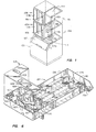
- FIGURE 1 is an isometric view of the exterior of an ice bin stacked with two ice making modules.
- FIGURE 1A is a schematic cross-sectional view of an ice bin stacked with two ice making modules.
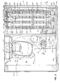
- FIGURE 2 is a top view of an ice maker module with its top panel removed.
- FIGURE 3 is a cross-sectional view, taken along section line 3 in Fig. 2, of an ice maker module.
- FIGURES 3A and 3B are, respectively, side and top cross-sectional views of a water level detection system for a sump in an ice maker module.
- FIGURE 4 is a cross-sectional view, taken along section line 4 in Fig. 2, of an ice maker module.
- FIGURE 5 is cross-sectional view, taken along section line 5 of Fig. 2, of a section of pan for delivering an even flow water to an evaporator for freezing and of a top section of an evaporator.
- FIGURE 6 is an isometric view of a pan for delivering an even flow of water to an evaporator.
- FIGURE 7 is an isometric view of two plates welded together to form an evaporator having a serpentine refrigerant channel.
- FIGURE 8 is a cross-section, taken along section line 8 of Fig. 7, of a traversal section of a refrigerant channel in the evaporator of Fig. 7.
- FIGURE 9 is a cross-section, taken along section line 8 of Fig. 7, a bend section of a refrigerant channel in the evaporator of Fig. 7.
- FIGURE 10 is a partially exploded isometric view of an evaporator.
- FIGURE 11 is a cross-section of the evaporator of Fig. 10 taken along section line 11.
- FIGURE 12 is a cross-section of the evaporator of Fig. 10 taken along section line 12.
- FIGURE 13 is a cross-section of the evaporator of Fig. 10 taken along section line 13.
- FIGURE 14 is a cross-section of the evaporator of Fig. 10 taken along section line 14.
- ice maker 101 includes an ice bin 103 and two ice making modules 105A and 105B, each substantially identical. Since ice making modules 105A and 105B are substantially identical, generally only one will be described, with reference to it as ice making module 105, though they will be distinguished where necessary.
- Ice bin 103 is an insulated, but not refrigerated, compartment for storing ice.
- Door 107 provides access to ice stored in ice bin 103. Ice bin 103 is not refrigerated to permit the ice to slowly melt and thereby prevent it from sticking together.
- An ice making module 105 houses refrigeration components, control circuitry and evaporators (not shown) for freezing water supplied to it into ice cubes. Ice making module 105 is shown with a front cover 109 cut away, displaying a wet compartment 111, in which evaporators (not shown) are place for making ice, and a dry compartment 115, in which is placed electrical equipment and other refrigeration circuitry (not shown). A wall portion of base 113 divides the wet compartment 111 and dry compartment 115 for confining water used to make ice to the wet compartment.
- Wet compartment 111 is defined on three sides and the bottom by base 113, with the remaining side covered by front cover 109.
- Dry compartment 115 is defined on bottom by a shelf portion of base 113, which portion is not shown in Figure 1, extending laterally from the wet compartment for mounting refrigeration circuitry in dry compartment 115.
- Base 113 is, in the preferred embodiment, fabricated from polyethylene material that is foamed in place for strength and dimensional control using rotocast techniques.
- the resulting base 113 is integrally formed, with double-wall construction; it has no joints that through which water can leak; it will not rust; and it has rigidity and strength.
- each base 113 defined by passage side-walls 119 integrally formed with base 113, is an ice passage 117 through which ice harvested in wet compartment 111 drops into ice bin 103.
- ice passage 117B in ice making module 105B opens into wet area 111A of ice making module 105A. Ice harvested from wet area 111B of ice making module 105B falls through wet area 111A and through ice passage 117A, ice passages 117A and 117B being vertically aligned when ice making module 105B is stacked on ice making module 105A.
- ice making module 105A and ice making module 105B For proper alignment of ice bin 103, ice making module 105A and ice making module 105B, raised tracks 121 on top of ice bin 103 mate with groove portions 123B of base 113. No fasteners are required for securing the weight of ice making module 105A and 105B being sufficient to secure them in place.
- Lid panel 127 closes the top of wet compartment 111B of ice making module 105B.
- the bottom of base 113B serves as a top to wet compartment 111A.
- FIGURE 1A a schematic cross-section of an ice maker shows ice making modules 105A and 105B stacked on ice bin 103.
- the bottom of ice making module 105A serves to enclose the top of ice bin 103.
- a transducer 129A for an acoustic range finding system using ultrasonic sound waves is mounted to the end of horn opening 131A. The transducer emits downwardly, through the horn, ultrasonic sound waves into ice bin 103 and receives echoes of the waves reflected from ice 133 or, as the case may be, the bottom of ice bin 103.
- ice making module 105B also includes a horn 131B, ice making modules 105A and 105B manufactured from the same mold.
- Horns 131A and 131B are integrally formed in bases 113A and 113B, respectively, near as possible to wall sections 135A and 135B, but on the side opposite ice passages 117A and 117B and in dry compartment 115A and 115B.
- a suitable range finding transducer 131 is made by Polaroid Corporation of Cambridge, Massachusetts for its ultrasonic ranging system.
- the range finding transducer is operated with a controller (not shown) located within each ice making module 105. Though the ranging operation of such a ultrasonic range finder is well known, briefly the controller operates it as follows.
- the controller issues an initiating signal to the transducer, typically by changing a bit level signal or by sending a pulse on an output line (not shown) connected to the transducer 131, causing it to emit ultrasonic sound pulse. Simultaneously, the controller records the time of the initiating signal and initiates a timer 137 that is set to a predetermined time.
- the transducer upon reception of an echo of the ultrasonic sound pulse, responds to the controller with a signal ("echo signal") on an input line (not shown). If on the other hand, the timer "times out", the time in which an echo should have been detected has passed, and the controller stops looking for the echo signal. The ranging is repeated with a new initiating signal. With a successful ranging, the controller stores the time difference between the initiating signal and the echo signal, and resets the timer. The controller then conducts several more, preferably up to eight, rangings, and then averages the times.
- the controller Comparing the average time with an expected time, the expected time being determined in advance and stored by the controller for a given ice level in the bin, the controller is able to determine the level of ice in the bin.
- an ice bin level selector 140 a user can select from a number of ice levels for which ranging times have been predetermined and stored in the controller.
- the functions of the controller is handled by a microcontroller that also handles all of the control functions of the ice making module. (See Fig. 15) The microcontroller initiates the rangings and uses the results to determine when to stop or to continue, as the case may be, ice making operations.
- Ice making module 105B or any ice making module stacked on top of another ice making module, is usually, for purposes of standardization, equipped with the ultrasonic sound transducer 129B.
- the controller in ice making module 105B operatively independently from that of ice making module 105A, will attempt to make rangings with transducer 129B. However, it will not be unable to do so because the top of the dry compartment 115A is so close to the transducer that the echo returns back that can be detected. So that the controller of the top ice making module 105B receives bin level information and does not go into an error mode when unable to carry out rangings, the controllers of both ice making modules 105A and 105B are coupled through a stacking or wiring harness.
- the wiring harness circuitry enables the controller of an ice making module to determine whether it is the top unit. Further, each of the controllers is provided with bin full in and bin full out lines.
- the wiring harness couples the bin full out line of the bottom unit to the bin full in line of the upper unit. When the transducer 129 in the bottom unit detects a full bin, the bin full line is turned on and both ice making modules stop making ice after termination of the next harvest.
- removing lid panel 127 (shown only in FIG. 1) of ice making module 105 reveals wet compartment 111 and dry compartment 115.
- dry compartment 115 Within dry compartment 115 is mounted standard, commercially available refrigeration components, compressor 201 and condenser 207.
- compressor 203 Shown in phantom is an alternate compressor 203.
- Compressor 203 has a larger capacity and is used with ice making modules 105 having four evaporators.
- Lower capacity compressor 201 is used with ice making modules having two evaporators.
- Compressor 201 or, as the case may be, compressor 203 is mounted within dry compartment 115 to shelf portion of base 113. Secured to shelf portion of base 113 is a steel plate 205, required by most municipal electrical codes and regulations. Compressed refrigerant from the output of compressor 201, or, if used, compressor 203, is provided through standard tubing (not shown) to condenser 207 for cooling. Cooled refrigerant from the output of condenser 207 then passes to an expansion valve (not shown) which lowers the pressure under which the refrigerant is compressed and thereby chills it. The chilled refrigerant is then provided to evaporators disposed within wet compartment 111. A solenoid actuated hot gas valve (not shown), selectively couples the output of the compressor 201 or 203 to the inputs of the evaporators so that hot, compressed gas may be provided to the evaporators for harvesting ice.
- compressor 201 or 203 Mounted above compressor 201 or 203 is electric motor 209 that drives fan 211. Rotating fan 211 fan draws in air through filter 213 and pressurizes the interior of ice making module 105. The pressurization forces air through condenser 207 in a uniform manner.
- electrical control box 215 In an upper portion of dry compartment 115 is electrical control box 215, in which is placed circuitry for controlling the operation of the ice making module 105.
- Water pump 217 Located within dry compartment 115 is a water pump 217.
- Water pump 217 includes an electric motor 218 coupled to a fan 219 and pump housing 225 (shown in phantom). Water pump 217 is mounted through plate 221 overlaying the top of sump 223, the pump housing 225 extending downwardly from the plate into sump 223. The motor 218 is placed above plate 221. Plate 221 acts as a splash guard against water in sump 223.
- Sump 223 is integrally formed within base 113 and serves as a reservoir for holding water to be circulated over evaporators 231A-231D (shown in phantom) and frozen into ice. Sump 223 extends between wet compartment 111 and dry compartment 115, beneath a common wall separating the two compartments, so that it collects water draining from the evaporators in wet compartment 111. The unfrozen but chilled water is recirculated by water pump 217 to water pan 227, located in wet compartment 111, through conduit 229.
- Water pan 227 delivers water to evaporators 231A-231D at predetermined rates and evenly distributes the water over the length of evaporators 231A-231D. Note that the evaporators are shown in phantom since water pan 227 sets on top of evaporators 231A-231D.
- water pan 227 includes three raised, island-like sections 233A-233C integrally formed with the water pan. They are located between adjacent evaporators 231A-231D, so as to form, with the edges of the water pan, water troughs that overlay evaporators 231A-231D.
- the function of raised sections 233A-233C is to reduce the amount of water in the water pan and turbulence in the pan that would interfere with an evenly distributed flow of water down the troughs.
- the water pan is not as well insulated as sump 223, and therefore it is preferable to keep the water in sump 223 so that it remains cool.
- the water pan maintains a depth of water in the tray necessary to ensure even and constant delivery and distribution of the water over a plurality of orifices 235 that are defined in and extend through the bottom of water pan 227.
- the depth of the water is determined by the height of exit weir 234.
- the orifices 235 provide water to the evaporators 231A-231D at a predetermined rate.
- Water delivery orifices 235 are arranged in pairs along the length of the water troughs. One of each pair of water delivery orifices 235 is disposed on either side of an evaporator 231.
- the pairs of orifices 235 are spaced apart on the length of water troughs such that each orifice 235 is centered between adjacent pairs insulating dividers 237 located on the faces of evaporators 231A-231D.
- Evaporators 231A-231D are supported within wet compartment 111 by vertical slots 239A-239D and by support bar 241.
- the vertical slots are located along the back wall of wet compartment 111 and are integrally formed in base 113.
- the ends 238A-238D of the evaporators are slid into and secured by vertical slots 239A-239D.
- Support bar 241 extends across the front of wet compartment 111 and supports the bottom of evaporators 231A-231D. Support bar 241 slides into, and is held up by, slots that are integrally defined in base 113. Secure mounting evaporators 231A-231D requires few or no fasteners.
- the front of both the wet compartment 111 and the dry compartment 115 is covered by integrally formed plastic front cover 109. Removal of the front cover provides easy, relatively unobstructed and simultaneous access to all components mounted in the wet and dry compartments for servicing. To facilitate its removal, as well as reduce the number of parts and complexity of manufacture, a minimum number of fasteners are used to secure it to the front of the ice making module. Further, no seals are employed between the wet compartment 111 and the front cover. Instead, lateral flanges 243 projecting inwardly from the front cover 109 into the wet compartment snugly engage a front portion of the inside walls of the wet compartment when the front cover is placed on the ice making module. The fit between the lateral flanges 243 and the inside walls of the wet compartment is sufficiently tight, and the flanges long enough, that water splashing inside the wet compartment is contained and does not leak.
- FIGURE 3 a cut-away, front view of ice module 105 taken along section line 3-3 of Fig. 2 shows the separation of wet compartment 111 and dry compartment 115 by wall section 301 of base 113.
- Sump 223 is as a reservoir for water that will be circulated over evaporators 231A-213D and made into ice. Water remaining unfrozen after being circulated over evaporators 231A-231D drains into sump 223 for recirculation by water pump 217.
- Plate section 221 is integrally formed with the top half 225A of pump housing 225.
- Motor 218 is mounted on plate 221, with shaft 303 extending through plate 221 for coupling the motor with impeller 303.
- the edges of plate 221 supports water pump 217 on side-walls 306 surrounding sump 223 and a flange portion of wall section 301.
- the bottom half 225B of pump housing 225 includes water openings (not shown) defined in its bottom side.
- water inlets of pump housing 225 remains submerged in water in the sump 223 so that the pump remains primed.
- Impeller 303 driven by motor 218, draws water in sump 223 into the pump housing 225 and pressurizes it.
- Pump housing discharges the water through sleeve section 307 of pump housing 225 and delivers it to water pan 227 via conduit 229.
- Conduit 229 is made of flexible tubing that is slipped over discharge sleeve 307.
- connection between sleeve 307 and conduit 229 is effectively sealed, and conduit 229 held in place, by an edge projecting outwardly from, and circumscribing, the end of discharge sleeve 307.
- the edge stretches the flexible tube, the elasticity of the tube creating an opposing sealing force against the edge.
- Pump housing 225 also has a second discharge opening that is located at the end of a tapered sleeve section 309 of pump housing 225. It is coupled to a drain (not shown) through conduit 311 and a solenoid-actuated purge valve 313 (shown symbolically). When not energized, purge valve 313 is closed, preventing discharge of pressurized water through sleeve 309. The purge valve remains closed during ice making or freezing portions of the ice maker cycle.
- the purge valve 313 is opened by energizing its solenoid. As purge valve 313 and its drain are located at a height below that of water pan 227, pressurized water in pump housing 225 discharges through purge valve 313 to the drain instead of through discharge sleeve 307, purge valve 313 being the path of least resistance. Some water, is, nevertheless, pumped up to the water pan. However, this flows back to the sump and, therefore, most of it is eventually pumped out. Only one valve is thus required for purging.
- an outwardly projecting edge circumscribing the opening in the end of sleeve 309 securely holds the conduit 311, made of flexible tubing, on the sleeve. Because sleeve 309 is located over sump 223, any leaked water drains into the sump.
- the sump 223 is filled with water to "full" level 317.
- the "full” level is below the top edge of passage side-walls 119 integrally formed in base 113 around ice passage 117.
- Low level 319 is above the water inlet openings of pump housing 225 so that water pump 217 remains primed.
- the volume of water between the "low” level and the “full” level is equal to the volume of water required to complete freezing of ice cubes on one evaporator 231.
- the number of filling operations during an ice making cycle thus equals the number of evaporators 231 disposed within the wet compartment 111.
- the volume of water between low level 319 and full level 317 can be set to be enough for ice cubes on all the evaporators, thereby completing freezing with only one fill of the sump; or only some fraction of the volume of water necessary to complete icing on one evaporator. Setting the difference between the low and full levels equal to one evaporator's worth of ice permits the sump to serve an odd number of evaporators and further permits the ice making module's controller (not shown, see Figure 15) to be easily adaptable to any number of evaporators.
- a molded plastic ice grate 315 Located beneath evaporators 231A-231D, but above "full" level 317, is a molded plastic ice grate 315. During the icing portion of the ice maker's cycle, unfrozen water drips through the ice grate 315 and is collected in sump 223. When the ice is harvested, ice grate 315 catches ice falling from the evaporators and directs it to ice passage 117 for delivery to the ice storage bin 103 (Fig. 1).
- Sump 223 shown in symbolic representation, has a low water level 319 and a high water or "full” level 317.
- a first self-heating thermistor 321 is located at low water level 319 ("low level thermistor"), and a second self-heating thermistor 323 is located at high water or "full" level 317. Both thermistors act as water level sensors.
- Thermistors 321 and 323 are temperature sensitive resistors, whose resistances depend on their temperature.
- Thermistors 321 and 323 are also of a type that is self-heating. In the air, the thermistors tend to remain hot. When submerged in water, however, their self-generating heat is quickly dissipated in the water, the water being a better conductor of heat than the air. Consequently, the resistance of the thermistor suffers a marked change in temperature, and therefore, resistance when being covered and uncovered by water. This wide range swing in resistances is quickly and easily detected by measuring the voltage drop across the thermistors when connected to a constant current source and comparing it to a threshold voltage.
- thermocouples thermocouples
- mechanical level detectors such as float switches and valves
- acoustical (ultrasonic) range finders are other types of sensors.
- Thermistors 321 and 323 are mounted on two probes, 325 and 327, respectively.
- Each probe is comprised of an integrally formed wire duct 329, splash curtain 331 and cone section 333.
- the upper end of wire duct 329 may be threaded, if desired, for adjustably securing the probes to mounting plate 330.
- Mounting plate 330 is supported over sump 223 by portions of base 113 around the edge of the sump and by plate 221 of water pump 217 (not shown, see Fig. 2).
- Each thermistor 321 and 323 is sealed in a solid glass capsule 335.
- the capsule is cylindrically shaped, its diameter being just large enough to accommodate the thermistor. Its length is sufficient to support the thermistor a predetermined distance above cone 333, the thermistor being placed in the upper end of the capsule and the lower end of the capsule extending through a hole defined in the middle of cone 333.
- a twin lead 337 extending down through the glass capsule 335 and the cone, and then around and up through wire duct 329.
- sealant 339 preferably a RTV sealant.
- FIGURE 3B shown is a cross-section taken along section 3B, of the two probes 325 and 327 of Fig. 3A, each being identical.
- Water is able to flow up between the splash barrier and around the cone 333 and glass capsule 335.
- the purpose and function of this arrangement is (1) to prevent water from randomly splashing on a thermistor and (2) to facilitate "shedding" of water by the thermistor while permitting the water level to be quickly and accurately detected by the thermistors.
- the splash barrier calms the water when it gets to levels where any turbulence may prematurely expose (in the case of low level thermistor 321), or cause water to be splashed on the thermistor and cause erroneous readings.
- the glass capsule 335 facilitates rapid shedding of water as the water level drops so that the change in temperature of the thermistor is rapid.
- Glass is used to encapsulate the thermistors because it is a good conductor of heat and it is non-corrosive. Mounting the glass capsule on top of a cone supports the capsule while ensuring that water is quickly shed and not trapped or held around the base of the capsule.
- this cross-sectional side view of wet compartment 111 shows one face of evaporator 231C.
- the faces of evaporator 231C (as well as those of evaporators 231A, 231B and 231D shown in Fig. 3) have an array of flat rectangular freezing or icing sites 401.
- the icing sites are vertically separated from each other by insulating plastic areas 403. They are horizontally separated by insulating plastic dividers 237 that extend outwardly from the face of the evaporator and have a pyramidal cross-section.
- the plastic areas 403 are made flush with the surface of the icing sites 401.
- the plastic dividers 237 taper in width from the top of the evaporator to the bottom of the evaporator. By tapering the plastic dividers, the space, or channel, between adjacent pairs of the dividers widens. Widening the channel permits ice cubes to slide down the channel during harvest without jamming or hanging up in the channel.
- the icing sites 401 are chilled by chilled refrigerant received on line 407 from the output of an expansion valve (not shown). Warmed refrigerant is returned to the compressor on line 405. Plastic areas 403 are not chilled. Water flowing over the freezing sites is thereby chilled with some of the freezing to the site but not to the plastic areas 403. Chilled, but unfrozen water, drains onto the bottom of base 113, and collects in sump 223. The chilled water is then pumped by pump 217 to water pan 227 via conduit 229 and recirculated over the face of the evaporator 231, with some of it freezing, if cold enough, to the surfaces of the icing sites or to ice already formed on the surface of the icing sites.
- front panel 109 is removable. It is secured to the front of ice making module 105 (Fig. 1) with a minimal number of fasteners to reduce the cost of manufacture and improve access time for repair. No seals are used.
- a flange section 408 is integrally molded into front cover 109 for extending over the seam where a front-wall section 407 of base 113 that defines one side of sump 223 meets front cover 109.
- Lateral flange 243 snugly fits against the inside of side wall 301 of the wet compartment to provide an adequate seal against water splashing into dry compartment 115 (Fig. 1).
- An opening 409 in the side wall 301 between the wet compartment and the dry compartment is provided for passing copper tubes carrying refrigerant from the refrigeration system, mounted in the dry compartment, to the evaporators mounted in the wet compartment.
- water pan 227 rests on edge 501 of water distribution cap 503, edge 501 meeting the bottom of water pan between adjacent pairs of orifices 235.
- Water distribution caps 503 are placed between the top edge of each evaporator 231A-231D and the water pan 227.
- Water distribution cap 503 includes two laterally projecting semi-circular members 505, integrally formed with but separated by edge 501, that extend from edge 501 to meet top edge piece 507 of evaporator 231B. Water distribution cap 503 also includes an integrally formed seat 511 which engages and rests on the top edge 507 of the evaporator so that evaporator 231B supports water pan 227. Semi-circular members 505 help to center seat 511 with respect to top edge piece 507.
- Each orifice 235 defined in the bottom of water pan 227 receives and collects water from the pan with a conically-shaped, funnel-like flow passage connected to a cylindrically-shaped flow passage for delivering a continuous and even stream of water to a semi-circular member 505 of water distribution cap 503.
- Surface tension of the water causes it flow around and laterally across the surface of each semi-circular member 505 into a sheet of water having relatively constant depth and a width equal to that of the icing sites 401 (Fig. 4).
- This sheet of water flows down each face of the evaporator 231B between adjacent dividers 237, and provides an even distribution of water across the entire width of the surface of each icing site on each evaporator.
- water pan 227 is integrally molded from a plastic material.
- Water pan 227 receives recirculating water from water pump 217 (Fig. 2) through water inlet opening 601.
- Water pumped through water inlet opening 601 is under pressure and turbulent.
- water existing in inlet opening 601 is passed through a manifold.
- Water inlet opening is located at one end of a manifold 603. The function of the manifold is to provide a smooth stream of water evenly distributed laterally across the front of the water pan so that it flows down the troughs between the raised sections 233A-233C and the side walls of the pan and exits over weir 234.
- Manifold cover 605 is sealed on top of the input manifold 603 so that the manifold is adequately pressurized.
- a series of weirs 607 integrally formed in the base of the water pan cooperates with a series of downward projections 609 integrally formed in manifold cover 605 to smooth out the water flow through the manifold and prevent eddies from forming.
- An opening between the manifold cover 605 and a wall 611 integrally formed in the water pan extends laterally across the front of the water pan at a predetermined height. Water pours from the opening , the water being under slight pressure, creating a flat, fountain-like stream evenly distributed laterally across the front of water pan that is relatively free of turbulence.
- the manifold cover 605 includes an upside-down "L"-shaped projection that extends outwardly from the manifold 603, over the opening to the water pan, and then downwardly to deflect water pouring out of the opening under too high of pressure.
- an evaporator 231 (Fig. 2) is assembled from two plates of stainless steel 701 and 703. Each plate is stamped with a continuous, serpentine-shaped (or "S" shaped) depressions. When the plates 701 and 703 meet, the serpentine depressions in each plate extend oppositely from each other. Since the depressions in each plate are mirror images, a continuous serpentine-shaped refrigerant channel is thereby formed and defined by plates 701 and 703. There refrigerant channel is sealed with a laser that welds a continuous hermetic seal along both sides of the refrigerant channel. There refrigerant channel has parallel sections 705 and bend sections 706.
- the cross-section of the channel in the bend sections 706 thickens and narrows toward the apex of the bend, so that the same cross-sectional area is maintained. By doing so, the bend sections 706 take up less space on the plates 701 and 703 and the flow of refrigerant is not disturbed. At its two ends, the refrigerant channel becomes rounded so that to accept tubing 707 from the refrigeration system for delivery of chilled refrigerant or hot gas, as the case may be, to the interior of the refrigerant channel.
- Cut between adjacent parallel section of refrigerant channel 705 are a series of slot openings 709 through which is secured insulating insert 403 (Fig. 4) that separates adjacent parallel sections of the refrigerant channel.
- Insulating material between adjacent parallel sections retards formation of ice between icing sites 401 (Fig. 4) so that ice bridges do not form between cubes forming on vertically adjacent icing sites.
- slots 709 also inhibit formation of ice bridges.
- Removing portions of the plates 701 and 703 increases the insulating effect of inserts. The inserts are not chilled by refrigerant in the channel 705. And, further, slots 709 permit replacement of the portions of the plates 701 and 703 with insulating material extending through the plates.
- icing sites 401 are the flat outer surfaces of plates 701 and 703 where they extend outwardly to define refrigerant channel 705.
- the flatness of the sides of the refrigerant channel 705 helps to assure that the chilling from refrigerant in the channel is uniform across the icing sites 401.
- the rate of heat transfer is improved by having only one layer of metal between the chilled refrigerant and the water.
- freezing water directly on a refrigerant carrying channel is termed freezing on a "primary surface”.
- Located between each section of refrigerant channel and slot opening 709 are continuous hermetic seal welds 801.
- heat transfer from the refrigerant in the channel to the icing site or primary surface may be, if desired, increased by texturing the inside surfaces. If texturing is desired, the inside surface of the evaporator plates 701 and 703 are either sand blasted or bead blasted. The inside surface may also be "coined” or "rifled".
- a section taken along plane 9-9 of a bend 706 in the refrigerant channel shows that the width of the channel becomes thicker as compared to the width of parallel sections 705 shown in shown in Fig. 8.
- the outside radius of bend is not the same as that of the inside radius of the parallel and bend sections of the refrigerant channel remaining the same so that no restriction impedes the even flow of the cross-sectional areas of refrigerant through the refrigerant channel.
- the assembled plates 701 and 703 are placed in an injection molding device for molding all plastic pieces directly onto the plate assembly. These pieces include: insulating areas 403, dividers 237, end piece 238, top edge 507, and end piece 1401.
- the refrigerant channel in the plate assembly is charged with refrigerant to 200 p.s.i. Because the depression in the plates 701 and 703 forming the refrigerant channels are not rounded, charging is necessary to prevent the collapse or bending of the refrigerant channel by the pressures of the injection molding process.
- Water distribution cap 503 is fitted to the top edge 507 to form an assembled evaporator 231.
- FIGURE 11 a cross-section of evaporator 231 taken along plane 11-11 in Fig. 10 shows how the bottom edge of the evaporator is finished with plastic insulating areas 403 that are molded around the bottom of plates 701 and 703.
- FIGURE 12 a cross-section of evaporator 231 in Fig. 10 taken along plane 12-12 shows that plastic insulating areas 403 are molded through slot 709 and have surfaces that are flush with icing sites 401.
- FIGURE 13 a cross-section taken along plane 13-13 (Fig. 10) of a parallel section 705 of the refrigerant channel, rounded opening 1301 receives tubing coupling the refrigeration channel to compressor 201 (Fig. 2).
- Plastic, laterally projecting sections 1303 prevent water from flowing or splashing off the front end of evaporator 231 (Fig. 10) next to the front cover 109 of ice making module 105 (See Fig. 2).
- plates 701 and 703 are encased by molded plastic end piece 238 for insertion into slot 239 (Fig. 2).
- FIGURE 14 a section of evaporator 231 taken along plane 14-14 (Fig. 10), laterally projecting sections 1303 are integrally formed with end piece 1401. End piece 1401 is molded around the edge of plates 701 and 703. Extending through slot 709 is plastic that forms insulating areas 403.
Landscapes
- Engineering & Computer Science (AREA)
- Physics & Mathematics (AREA)
- Mechanical Engineering (AREA)
- Thermal Sciences (AREA)
- General Engineering & Computer Science (AREA)
- Chemical & Material Sciences (AREA)
- Combustion & Propulsion (AREA)
- Production, Working, Storing, Or Distribution Of Ice (AREA)
Description
- The invention pertains to an evaporator for freezing water into ice making machines and methods for ice cubes. Such an evaporator can be part of self-contained machines for making ice cubes ("ice cubers"). The invention further pertains to a method for manufacturing an evaporator for ice makers.
- There are basically two types of ice makers: household units in refrigerators; and self-contained commercial units for use in hotels, restaurants, bars, hospitals and other establishments that require large amounts of ice. Commercial units are further dividable into two types, depending on the type of ice they make: flaked or cubed.
- Unlike household ice makers which freeze water in a tray with cool air in a refrigerated compartment, a commercial ice cube maker circulates a steady stream of water over a chilled ice mold to deposit thin layers of ice in the pockets of the mold for building into ice cubes. Water that does not freeze after being circulated over the ice mold is collected in a sump and recirculated over the chilled mold until it cools enough to freeze. After ice cubes are formed, they are harvested from the mold and stored in an unrefrigerated ice bin from which they may be retrieved. The bin remains unrefrigerated so that the ice melts slowly, thereby preventing it from sticking together.
- Cold refrigerant from a refrigeration circuit chills the ice mold. In a typical refrigeration circuit, a compressor driven by an electric motor that compresses refrigerant to a high pressure and supplies it to a condenser. The condenser cools the compressed refrigerant with air blown across coils with a fan or with water. The refrigerant is then passed through an expansion valve, the expansion valve dropping the pressure of the refrigerant considerably, thereby cooling it. The cooled refrigerant then flows through copper tubing that has been welded to the back of a copper plate, called the evaporator plate. Welded to the evaporator plate is a lattice-like copper structure that is used to mold the ice into cubes. Together, the lattice-like structure and the evaporator plate form the ice mold. Taken together, the ice mold and the copper tubing are simply referred to as the evaporator.
- An electronic controller, sometimes microprocessor-based, operates the fans, motors, pumps and valves that control the functioning of the ice maker.
- Commercial ice makers are expected to continuously and reliably produce substantial amounts of ice. They are used in service industries, where a unit breaking down or producing insufficient ice causes disruptions of service. When there is no ice, service suffers and customers are quickly irritated: few people, for example, enjoy warm soft drinks. An unreliable ice maker will quickly erode a firm's goodwill and its business. An unreliable ice maker also costs the manufacturer money and goodwill. When the ice maker is down, its manufacturer must spend money either quickly repairing it or furnishing substitute ice.
- A better ice cube is generally not sought, just a less expensive one, ice being a fungible commodity. Therefore, in addition to reliability, holding down the cost of an ice maker by controlling the cost of manufacturing and operation is a paramount concern in the art. Low cost operation requires that ice be made efficiently by conserving electricity and water; and further that the ice maker be nearly maintenance-free, as down-time for maintenance costs money and someone must be paid to do it. Low cost operation and maintenance must extend over many years, as ice makers are expected to have long, productive lives.
- Efforts to achieve low cost, efficient, highly reliable operation are beset by a number of problems, most of all by the fact that cost, efficiency and reliability are frequently traded one for the other in designing and manufacturing ice makers. Some, but by no means all, of the common problem areas are: manufacturing a structure for ice making operation; harvesting ice; handling of water; manufacturing the evaporator; and generally controlling the operation of the ice maker, including initiating and terminating freezing and harvesting, purging and detection of ice levels in the ice bin.
- Problems associated with harvesting the ice center around the fact that ice cubes freeze to the surfaces of the ice molds. The most common harvesting method is, not surprisingly, to unfreeze them by quickly warming the evaporator and melting the ice immediately adjacent to the surfaces of the mold. To warm the evaporator, the cycle of the refrigeration circuit is essentially reversed by opening a solenoid-operated valve (termed a hot gas solenoid or valve) to permit hot refrigerant from the compressor to flow directly into the evaporator. This method is termed in the art a hot gas defrost.
- Despite the unfreezing, the cubes often do not simply fall out of the ice mold. Water from the melting ice creates a "capillary"-like action that tends to suck the cubes into the pockets of the ice mold. Gravity is often used to overcome this capillary-like action. The evaporator is oriented so that the pockets of the ice mold face down, or it is placed vertically and equipped with downwardly slanting pockets. However, even gravity cannot always be relied on to ensure that all the ice cubes are harvested simultaneously for quick harvesting and energy efficiency. Mechanical means are sometimes used in the place of, and sometimes in conjunction with, gravity to nudge or assist the ice. To simplify the mechanical means, water is recirculated over the ice mold until ice bridges are formed between the ice cubes thereby connecting the cubes into a single sheet of ice that can be pushed out of the mold. The bridges are thin and usually break easily after harvesting. Using a mechanical means for dislodging ice, however, increases the cost of manufacturing and makes the ice maker more prone to malfunction. Further, in order to freeze ice bridges between ice cubes, the freezing or icing portion of an ice making cycle must be extended to ensure that sufficiently strong ice bridges are formed between all the cubes in the pockets. Increasing the freezing time reduces ice making capacity and efficiency.
- The problems of water are how to keep it from leaking out, and how to reduce its corrosive effects on equipment. Making ice requires a lot of water, and therefore also requires a water tight means of handling it so that it will not spill on the floor, get electrical components wet or corrode the interior of the ice maker. When orienting an evaporator vertically, water to be frozen cascades down the front of the ice mold, causing water to splash and creates a waterfall of unfrozen water at the bottom of the evaporator. The unfrozen water is collected in a reservoir or sump and recirculated over the evaporator. Constructing a structure to deal with this water without leaking usually involves seals having all sorts of clamps, screws, and other types of fasteners to make them water-tight. Consequently, assembly, maintenance and repair are complicated; the number of possible failure modes increases; and costs generally go up. Protecting metal parts against corrosion caused by the water and humidity, or using corrosion-resistant metals in the parts, also costs money and assembly time.
- In addition to designing an evaporator that improves harvesting, manufacturing them tends to be expensive. In an evaporator refrigerant passes through a coiled copper tube. Copper is chosen because of its inherent property of good heat transference. The copper tube is welded to an evaporator plate in a coiled fashion. A lattice-like copper structure is then welded to the other side of the evaporator plate for creating the ice mold. Welding ensures good transference of heat. The entire evaporator is constructed of copper, as mating copper against other types of metals generally reduces rates of heat transfer. Constructing the evaporator is, consequently, labor intensive and expensive. Further, only one side of an evaporator can be used to make ice; a second plate cannot be easily welded to the copper tube once the first has been welded.
- DE-A-1 601 076 discloses an evaporator for freezing water into ice cubes according to the pre-characterizing part of claim 1. The means for impeding formation of ice bridges between adjacent icing sites are in the form of inserts of insulating material located on the outer surface of the second plate between the parallel sections of the depression, wherein the insulating material is vertically spaced apart adjacent icing sites in the array of icing sites.
- The parallel sections are formed by providing alternating partition walls disposed in vertically spaced relationship, wherein at the end of every second partition wall there is provided an opening which connects two adjacent parallel sections.
- The problem underlying the present invention is to provide for an evaporator for freezing water into ice cubes according to the pre-characterizing part of claim 1, wherein highly efficient means for impeding the formation of ice bridges between adjacent icing sites are provided.
- This is achieved according to the present invention by the features of claim 1. In addition, the present invention provides for a method of manufacturing an evaporator having the features of claim 11.
- The slots defined in the second plate between adjacent parallel sections of the depression combined with the matching slots in the first plate and with the inserts of insulating material disrupt a conductive path so as to impede the formation of icing bridges in the region of the slots.
- The preferred embodiment of the invention is a new generation of commercial, self-contained ice cube maker having a new overall design and a complement of improved components. The design of each of the components, singularly and collectively, reduce the cost manufacturing, maintenance and operation, and increase reliability of operation of the ice cuber.
- The design of the ice maker is modular, having one or more vertically stacked ice making modules on top of a commonly shared ice bin. Each ice making module is a self-contained unit that includes refrigeration circuitry and control circuitry. Each operates independently. Housings for the ice making module are constructed such that one or more of them may be stacked vertically, without the aid of fasteners or special modification, on top of a common ice bin. The capacity of an ice cuber is thus easily increased or decreased, before or after installation. Plugs are provided for connecting in a daisy chain a shared ice bin level sensor so that all ice making modules stop making ice when the ice bin is full.
- The construction and manufacture of an ice making module solve a number of problems relating to reliability and cost. The module has an integrally formed, rotocast plastic base. The base has three walls and a bottom integrally formed therein that surround a "wet" compartment and separate it from a "dry" area. It further includes an integrally molded sump for holding water to be recirculated over the evaporators. Within the wet area is an evaporator for forming the ice, over which is set a water pan that distributes water among, and provides a constant, even and smooth flow of water to, the evaporators. In the dry area are mounted the compressor motor, condenser, fan, water pump and control circuitry. The integrally formed base structure eliminates the need for folded, fitted and hemmed edges for metal casework and corrosion protection. Creating a wet area within an integrally formed plastic base significantly reduces the number of joints from which water may leak and eliminates many of fasteners that may be otherwise required. Assembly costs are thus reduced, and keeping the electrical equipment dry increases reliability of operation.
- Carrying through on the modular design concept, the wet area accommodates from one to four evaporators placed within slots integrally formed with the base. Each ice making module is easily adaptable to handle this range of ice making capacities. Many of the components designed to support expansion are easily adaptable. Housing fewer components to support a line of ice makers having a range of capacities reduces overall manufacturing costs and improves reliability with better quality control.
- The evaporators are constructed from two sheets of stainless steel laser-welded together. Formed within each sheet of stainless steel is a continuous depression that traverses across the sheet, turning 180 degrees at the edges of the sheet, in a "serpentine" pattern. When the two sheets are welded together between the depressions, the edges of the depressions meet and thereby form a serpentine refrigerant channel through which refrigerant passes. Water is directly frozen on the outside of the channel, directly on a "primary" surface. To create cubes of ice and to prevent formation of ice bridges between them, plastic insulators are inserted between adjacent transversing sections of the refrigerant channel and vertical dividers protruding from the surface of the evaporator are added, thereby dividing the surface of the refrigerant channel into an array of icing sites. Water flows down each surface, freezing as it trickles over the icing sites thereby building an ice cube.
- The all stainless steel construction of an evaporator makes it corrosion-proof. It is easily manufactured, requiring no coiled copper tubing to carry chilled refrigerant, no evaporator plates welded to the coil, and no copper ice molds. Whereas only one side of prior art evaporators is used to form ice, both sides of the present evaporator are used to form ice, thereby increasing its ice making capacity and efficiency. Shortening the distance between chilled refrigerant and the water to be frozen by forming the ice directly on the refrigerant channel increases the rate of heat transfer between the water and refrigerant, making the evaporator and the ice cuber more energy efficient. Flattening the sides of the refrigerant channel also equalizes the heat transfer rate across the icing site, further improving efficiency.
- The construction of the evaporator improves reliability and efficiency in harvesting the ice. The flat surface of the evaporator, without any pockets in which to form the ice cubes, eliminates any need for mechanical means to dislodge the ice. Furthermore, the effect of the capillary-like force in the pockets that develops when warming the evaporator during harvesting is minimized. The force of gravity pulls the ice parallel to the flat surface of the evaporator and down into an ice storage bin.
- These and other advantages and novel features of the invention are described with reference to the annexed drawings depicting the preferred embodiment of the invention.
- FIGURE 1 is an isometric view of the exterior of an ice bin stacked with two ice making modules.
- FIGURE 1A is a schematic cross-sectional view of an ice bin stacked with two ice making modules.
- FIGURE 2 is a top view of an ice maker module with its top panel removed. FIGURE 3 is a cross-sectional view, taken along
section line 3 in Fig. 2, of an ice maker module. - FIGURES 3A and 3B are, respectively, side and top cross-sectional views of a water level detection system for a sump in an ice maker module.
- FIGURE 4 is a cross-sectional view, taken along section line 4 in Fig. 2, of an ice maker module.
- FIGURE 5 is cross-sectional view, taken along section line 5 of Fig. 2, of a section of pan for delivering an even flow water to an evaporator for freezing and of a top section of an evaporator.
- FIGURE 6 is an isometric view of a pan for delivering an even flow of water to an evaporator.
- FIGURE 7 is an isometric view of two plates welded together to form an evaporator having a serpentine refrigerant channel.
- FIGURE 8 is a cross-section, taken along
section line 8 of Fig. 7, of a traversal section of a refrigerant channel in the evaporator of Fig. 7. - FIGURE 9 is a cross-section, taken along
section line 8 of Fig. 7, a bend section of a refrigerant channel in the evaporator of Fig. 7. - FIGURE 10 is a partially exploded isometric view of an evaporator.
- FIGURE 11 is a cross-section of the evaporator of Fig. 10 taken along section line 11.
- FIGURE 12 is a cross-section of the evaporator of Fig. 10 taken along section line 12.
- FIGURE 13 is a cross-section of the evaporator of Fig. 10 taken along
section line 13. - FIGURE 14 is a cross-section of the evaporator of Fig. 10 taken along
section line 14. - In the following written description of the preferred embodiment shown in the drawings, like reference numbers refer to like elements. Where there is a multiple number of substantially the same element depicted, the elements are identified with the same reference number, but different letters may be appended to the end of the same reference number where it its helpful to the description to identify a particular one of these elements. For example, a description referencing element "10" applies to elements marked by "10A", etc.
- Referring now to FIGURE 1, ice maker 101 includes an
ice bin 103 and twoice making modules ice making modules -
Ice bin 103 is an insulated, but not refrigerated, compartment for storing ice.Door 107 provides access to ice stored inice bin 103.Ice bin 103 is not refrigerated to permit the ice to slowly melt and thereby prevent it from sticking together. - An ice making module 105 houses refrigeration components, control circuitry and evaporators (not shown) for freezing water supplied to it into ice cubes. Ice making module 105 is shown with a
front cover 109 cut away, displaying awet compartment 111, in which evaporators (not shown) are place for making ice, and adry compartment 115, in which is placed electrical equipment and other refrigeration circuitry (not shown). A wall portion ofbase 113 divides thewet compartment 111 anddry compartment 115 for confining water used to make ice to the wet compartment. -
Wet compartment 111 is defined on three sides and the bottom bybase 113, with the remaining side covered byfront cover 109.Dry compartment 115 is defined on bottom by a shelf portion ofbase 113, which portion is not shown in Figure 1, extending laterally from the wet compartment for mounting refrigeration circuitry indry compartment 115. -
Base 113 is, in the preferred embodiment, fabricated from polyethylene material that is foamed in place for strength and dimensional control using rotocast techniques. The resultingbase 113 is integrally formed, with double-wall construction; it has no joints that through which water can leak; it will not rust; and it has rigidity and strength. - Within each base 113, defined by passage side-
walls 119 integrally formed withbase 113, is anice passage 117 through which ice harvested inwet compartment 111 drops intoice bin 103. When multiple ice making modules are stacked as shown,ice passage 117B inice making module 105B opens into wet area 111A ofice making module 105A. Ice harvested from wet area 111B ofice making module 105B falls through wet area 111A and throughice passage 117A,ice passages ice making module 105B is stacked onice making module 105A. - For proper alignment of
ice bin 103,ice making module 105A andice making module 105B, raisedtracks 121 on top ofice bin 103 mate withgroove portions 123B ofbase 113. No fasteners are required for securing the weight ofice making module ice making module 105B. The bottom ofbase 113B serves as a top to wet compartment 111A. - Referring now to FIGURE 1A, a schematic cross-section of an ice maker shows
ice making modules ice bin 103. The bottom ofice making module 105A serves to enclose the top ofice bin 103. Atransducer 129A for an acoustic range finding system using ultrasonic sound waves is mounted to the end ofhorn opening 131A. The transducer emits downwardly, through the horn, ultrasonic sound waves intoice bin 103 and receives echoes of the waves reflected from ice 133 or, as the case may be, the bottom ofice bin 103. Though it is not used,ice making module 105B also includes ahorn 131B,ice making modules Horns bases sections 135A and 135B, but on the side oppositeice passages dry compartment - A suitable
range finding transducer 131 is made by Polaroid Corporation of Cambridge, Massachusetts for its ultrasonic ranging system. The range finding transducer is operated with a controller (not shown) located within each ice making module 105. Though the ranging operation of such a ultrasonic range finder is well known, briefly the controller operates it as follows. The controller issues an initiating signal to the transducer, typically by changing a bit level signal or by sending a pulse on an output line (not shown) connected to thetransducer 131, causing it to emit ultrasonic sound pulse. Simultaneously, the controller records the time of the initiating signal and initiates a timer 137 that is set to a predetermined time. The transducer, upon reception of an echo of the ultrasonic sound pulse, responds to the controller with a signal ("echo signal") on an input line (not shown). If on the other hand, the timer "times out", the time in which an echo should have been detected has passed, and the controller stops looking for the echo signal. The ranging is repeated with a new initiating signal. With a successful ranging, the controller stores the time difference between the initiating signal and the echo signal, and resets the timer. The controller then conducts several more, preferably up to eight, rangings, and then averages the times. Comparing the average time with an expected time, the expected time being determined in advance and stored by the controller for a given ice level in the bin, the controller is able to determine the level of ice in the bin. With an ice bin level selector 140, a user can select from a number of ice levels for which ranging times have been predetermined and stored in the controller. In the preferred embodiment, the functions of the controller is handled by a microcontroller that also handles all of the control functions of the ice making module. (See Fig. 15) The microcontroller initiates the rangings and uses the results to determine when to stop or to continue, as the case may be, ice making operations. -
Ice making module 105B, or any ice making module stacked on top of another ice making module, is usually, for purposes of standardization, equipped with theultrasonic sound transducer 129B. The controller inice making module 105B, operatively independently from that ofice making module 105A, will attempt to make rangings withtransducer 129B. However, it will not be unable to do so because the top of thedry compartment 115A is so close to the transducer that the echo returns back that can be detected. So that the controller of the topice making module 105B receives bin level information and does not go into an error mode when unable to carry out rangings, the controllers of bothice making modules - Referring now to FIGURE 2, removing lid panel 127 (shown only in FIG. 1) of ice making module 105 reveals
wet compartment 111 anddry compartment 115. Withindry compartment 115 is mounted standard, commercially available refrigeration components,compressor 201 andcondenser 207. Shown in phantom is analternate compressor 203.Compressor 203 has a larger capacity and is used with ice making modules 105 having four evaporators.Lower capacity compressor 201 is used with ice making modules having two evaporators. There is no limit inherent to ice making module on the number of evaporators placed in the wet compartment, except for the physical size of the compartment and the space required for refrigeration components large enough to chill the evaporators.Compressor 201 or, as the case may be,compressor 203 is mounted withindry compartment 115 to shelf portion ofbase 113. Secured to shelf portion ofbase 113 is asteel plate 205, required by most municipal electrical codes and regulations. Compressed refrigerant from the output ofcompressor 201, or, if used,compressor 203, is provided through standard tubing (not shown) tocondenser 207 for cooling. Cooled refrigerant from the output ofcondenser 207 then passes to an expansion valve (not shown) which lowers the pressure under which the refrigerant is compressed and thereby chills it. The chilled refrigerant is then provided to evaporators disposed withinwet compartment 111. A solenoid actuated hot gas valve (not shown), selectively couples the output of thecompressor - Mounted above
compressor electric motor 209 that drivesfan 211.Rotating fan 211 fan draws in air through filter 213 and pressurizes the interior of ice making module 105. The pressurization forces air throughcondenser 207 in a uniform manner. - In an upper portion of
dry compartment 115 is electrical control box 215, in which is placed circuitry for controlling the operation of the ice making module 105. - Located within
dry compartment 115 is awater pump 217.Water pump 217 includes anelectric motor 218 coupled to afan 219 and pump housing 225 (shown in phantom).Water pump 217 is mounted throughplate 221 overlaying the top ofsump 223, thepump housing 225 extending downwardly from the plate intosump 223. Themotor 218 is placed aboveplate 221. Plate 221 acts as a splash guard against water insump 223. -
Sump 223 is integrally formed withinbase 113 and serves as a reservoir for holding water to be circulated overevaporators 231A-231D (shown in phantom) and frozen into ice.Sump 223 extends betweenwet compartment 111 anddry compartment 115, beneath a common wall separating the two compartments, so that it collects water draining from the evaporators inwet compartment 111. The unfrozen but chilled water is recirculated bywater pump 217 towater pan 227, located inwet compartment 111, throughconduit 229. -
Water pan 227 delivers water toevaporators 231A-231D at predetermined rates and evenly distributes the water over the length ofevaporators 231A-231D. Note that the evaporators are shown in phantom sincewater pan 227 sets on top ofevaporators 231A-231D. - Many of the details of the
water pan 227 are discussed in connection with Figure 6. Briefly, however,water pan 227 includes three raised, island-like sections 233A-233C integrally formed with the water pan. They are located betweenadjacent evaporators 231A-231D, so as to form, with the edges of the water pan, water troughs that overlay evaporators 231A-231D. The function of raisedsections 233A-233C is to reduce the amount of water in the water pan and turbulence in the pan that would interfere with an evenly distributed flow of water down the troughs. The water pan is not as well insulated assump 223, and therefore it is preferable to keep the water insump 223 so that it remains cool. - The water pan maintains a depth of water in the tray necessary to ensure even and constant delivery and distribution of the water over a plurality of
orifices 235 that are defined in and extend through the bottom ofwater pan 227. The depth of the water is determined by the height ofexit weir 234. Theorifices 235 provide water to theevaporators 231A-231D at a predetermined rate.Water delivery orifices 235 are arranged in pairs along the length of the water troughs. One of each pair ofwater delivery orifices 235 is disposed on either side of an evaporator 231. The pairs oforifices 235 are spaced apart on the length of water troughs such that eachorifice 235 is centered between adjacentpairs insulating dividers 237 located on the faces ofevaporators 231A-231D. -
Evaporators 231A-231D are supported withinwet compartment 111 byvertical slots 239A-239D and by support bar 241. The vertical slots are located along the back wall ofwet compartment 111 and are integrally formed inbase 113. The ends 238A-238D of the evaporators are slid into and secured byvertical slots 239A-239D. Support bar 241 extends across the front ofwet compartment 111 and supports the bottom ofevaporators 231A-231D. Support bar 241 slides into, and is held up by, slots that are integrally defined inbase 113. Secure mountingevaporators 231A-231D requires few or no fasteners. - The front of both the
wet compartment 111 and thedry compartment 115 is covered by integrally formed plasticfront cover 109. Removal of the front cover provides easy, relatively unobstructed and simultaneous access to all components mounted in the wet and dry compartments for servicing. To facilitate its removal, as well as reduce the number of parts and complexity of manufacture, a minimum number of fasteners are used to secure it to the front of the ice making module. Further, no seals are employed between thewet compartment 111 and the front cover. Instead,lateral flanges 243 projecting inwardly from thefront cover 109 into the wet compartment snugly engage a front portion of the inside walls of the wet compartment when the front cover is placed on the ice making module. The fit between thelateral flanges 243 and the inside walls of the wet compartment is sufficiently tight, and the flanges long enough, that water splashing inside the wet compartment is contained and does not leak. - Referring now to FIGURE 3, a cut-away, front view of ice module 105 taken along section line 3-3 of Fig. 2 shows the separation of
wet compartment 111 anddry compartment 115 bywall section 301 ofbase 113.Sump 223, defined within thebottom base 113 by integrally formed side-wall sections, extends partially intowet compartment 111 and intodry compartment 115 beneathwall section 301.Sump 223 is as a reservoir for water that will be circulated overevaporators 231A-213D and made into ice. Water remaining unfrozen after being circulated overevaporators 231A-231D drains intosump 223 for recirculation bywater pump 217. Excess water inwater pan 227 that overflowsweir 234 also drains intosump 223. The bottom section ofbase 113 withinwet compartment 111 is sloped downwardly into the sump so that the unfrozen water tends to pool in the sump. -
Plate section 221 is integrally formed with thetop half 225A ofpump housing 225.Motor 218 is mounted onplate 221, withshaft 303 extending throughplate 221 for coupling the motor withimpeller 303. The edges ofplate 221 supportswater pump 217 on side-walls 306 surroundingsump 223 and a flange portion ofwall section 301. - The
bottom half 225B ofpump housing 225 includes water openings (not shown) defined in its bottom side. During operation, water inlets ofpump housing 225 remains submerged in water in thesump 223 so that the pump remains primed.Impeller 303, driven bymotor 218, draws water insump 223 into thepump housing 225 and pressurizes it. Pump housing discharges the water throughsleeve section 307 ofpump housing 225 and delivers it towater pan 227 viaconduit 229.Conduit 229 is made of flexible tubing that is slipped overdischarge sleeve 307. The connection betweensleeve 307 andconduit 229 is effectively sealed, andconduit 229 held in place, by an edge projecting outwardly from, and circumscribing, the end ofdischarge sleeve 307. The edge stretches the flexible tube, the elasticity of the tube creating an opposing sealing force against the edge. As the connection betweendischarge sleeve 307 andconduit 229 is located withinwet compartment 111, any water that may leak from between the discharge sleeve and the conduit tubing is returned to thesump 223. -
Pump housing 225 also has a second discharge opening that is located at the end of atapered sleeve section 309 ofpump housing 225. It is coupled to a drain (not shown) through conduit 311 and a solenoid-actuated purge valve 313 (shown symbolically). When not energized,purge valve 313 is closed, preventing discharge of pressurized water throughsleeve 309. The purge valve remains closed during ice making or freezing portions of the ice maker cycle. - When water freezes to the evaporators, minerals suspended in the water are not typically trapped in the ice matrix, but are washed away by the unfrozen water. The ice, therefore tends to be pure, but the mineral content of the water is always increasing as water is frozen. Consequently, water is purged during harvesting to avoid mineral build-up in the water. For purging of mineral-laden water from the
sump 223, thepurge valve 313 is opened by energizing its solenoid. Aspurge valve 313 and its drain are located at a height below that ofwater pan 227, pressurized water inpump housing 225 discharges throughpurge valve 313 to the drain instead of throughdischarge sleeve 307,purge valve 313 being the path of least resistance. Some water, is, nevertheless, pumped up to the water pan. However, this flows back to the sump and, therefore, most of it is eventually pumped out. Only one valve is thus required for purging. - Like
sleeve 307, an outwardly projecting edge circumscribing the opening in the end ofsleeve 309 securely holds the conduit 311, made of flexible tubing, on the sleeve. Becausesleeve 309 is located oversump 223, any leaked water drains into the sump. - During the ice making or freezing portion of the ice maker's operating cycle, the
sump 223 is filled with water to "full"level 317. The "full" level is below the top edge of passage side-walls 119 integrally formed inbase 113 aroundice passage 117.Low level 319 is above the water inlet openings ofpump housing 225 so thatwater pump 217 remains primed. When the water in the sump falls to "low"level 319, it is refilled to thefull level 317 if more water is needed for freezing into ice cubes before harvest of the ice cubes is begun. - In the preferred embodiment, the volume of water between the "low" level and the "full" level is equal to the volume of water required to complete freezing of ice cubes on one evaporator 231. The number of filling operations during an ice making cycle thus equals the number of evaporators 231 disposed within the
wet compartment 111. By counting the number of times the sump is refilled, or more particularly the number of times the water falls to the "low" level, the ice making module determines when to initiate harvesting of the ice, harvesting beginning when the water level drops to the "low" level the last time. However, the volume of water betweenlow level 319 andfull level 317 can be set to be enough for ice cubes on all the evaporators, thereby completing freezing with only one fill of the sump; or only some fraction of the volume of water necessary to complete icing on one evaporator. Setting the difference between the low and full levels equal to one evaporator's worth of ice permits the sump to serve an odd number of evaporators and further permits the ice making module's controller (not shown, see Figure 15) to be easily adaptable to any number of evaporators. - However, if accommodation of an undetermined number of controllers is not desired, the most efficient operation would be to make the difference between low and full levels equal to the amount of water to complete ice making on all evaporators running of the sump. Each refill adds warm water that must be chilled. This warm water melts some the ice already formed on the evaporator, that will have to be refrozen. However, since the
wet compartment 111 is not cooled, water in the sump will gain heat. Therefore, it may be desirable is some circumstances to keep less water on hand in the sump than is required for complete freezing. The amount of water kept in the sump at which the best energy efficiency must be determined empirically. - Located beneath
evaporators 231A-231D, but above "full"level 317, is a moldedplastic ice grate 315. During the icing portion of the ice maker's cycle, unfrozen water drips through theice grate 315 and is collected insump 223. When the ice is harvested,ice grate 315 catches ice falling from the evaporators and directs it toice passage 117 for delivery to the ice storage bin 103 (Fig. 1). - Please now refer to FIGURE 3A for a description of the method and apparatus for controlling the level of water in the
sump 223.Sump 223, shown in symbolic representation, has alow water level 319 and a high water or "full"level 317. A first self-heating thermistor 321 is located at low water level 319 ("low level thermistor"), and a second self-heating thermistor 323 is located at high water or "full"level 317. Both thermistors act as water level sensors. -
Thermistors 321 and 323 are temperature sensitive resistors, whose resistances depend on their temperature.Thermistors 321 and 323 are also of a type that is self-heating. In the air, the thermistors tend to remain hot. When submerged in water, however, their self-generating heat is quickly dissipated in the water, the water being a better conductor of heat than the air. Consequently, the resistance of the thermistor suffers a marked change in temperature, and therefore, resistance when being covered and uncovered by water. This wide range swing in resistances is quickly and easily detected by measuring the voltage drop across the thermistors when connected to a constant current source and comparing it to a threshold voltage. The change is so dramatic that any variations induced caused by the insulating effect of mineral deposits, corrosion or age is insignificant. Consequently, self-heating thermistors are preferred as water level sensors or transducers because mineral deposits from the water and corrosion do not effect their operation. However, other types of sensors may be used: thermocouples; mechanical level detectors, such as float switches and valves; and acoustical (ultrasonic) range finders. -
Thermistors 321 and 323 are mounted on two probes, 325 and 327, respectively. Each probe is comprised of an integrally formedwire duct 329,splash curtain 331 andcone section 333. The upper end ofwire duct 329 may be threaded, if desired, for adjustably securing the probes to mounting plate 330. Mounting plate 330 is supported oversump 223 by portions ofbase 113 around the edge of the sump and byplate 221 of water pump 217 (not shown, see Fig. 2). - Each
thermistor 321 and 323 is sealed in asolid glass capsule 335. The capsule is cylindrically shaped, its diameter being just large enough to accommodate the thermistor. Its length is sufficient to support the thermistor a predetermined distance abovecone 333, the thermistor being placed in the upper end of the capsule and the lower end of the capsule extending through a hole defined in the middle ofcone 333. From eachthermistor 321 and 323 is atwin lead 337 extending down through theglass capsule 335 and the cone, and then around and up throughwire duct 329. So that no water finds its way up through thewire duct 329 and the opening in thecone 333, and so that the wire leads 337 do not get wet, the opening at the bottom of the wire duct and the chamber undercone 333 are completely filled after they are installed withsealant 339, preferably a RTV sealant. - Please now refer to FIGURE 3B, shown is a cross-section taken along
section 3B, of the twoprobes cone 333 andglass capsule 335. The purpose and function of this arrangement is (1) to prevent water from randomly splashing on a thermistor and (2) to facilitate "shedding" of water by the thermistor while permitting the water level to be quickly and accurately detected by the thermistors. The splash barrier calms the water when it gets to levels where any turbulence may prematurely expose (in the case of low level thermistor 321), or cause water to be splashed on the thermistor and cause erroneous readings. Theglass capsule 335 facilitates rapid shedding of water as the water level drops so that the change in temperature of the thermistor is rapid. Glass is used to encapsulate the thermistors because it is a good conductor of heat and it is non-corrosive. Mounting the glass capsule on top of a cone supports the capsule while ensuring that water is quickly shed and not trapped or held around the base of the capsule. - Referring now to FIGURE 4, this cross-sectional side view of
wet compartment 111 shows one face ofevaporator 231C. The faces ofevaporator 231C (as well as those ofevaporators icing sites 401. The icing sites are vertically separated from each other by insulatingplastic areas 403. They are horizontally separated by insulatingplastic dividers 237 that extend outwardly from the face of the evaporator and have a pyramidal cross-section. Theplastic areas 403 are made flush with the surface of theicing sites 401. Theplastic dividers 237, as shown in the figure, taper in width from the top of the evaporator to the bottom of the evaporator. By tapering the plastic dividers, the space, or channel, between adjacent pairs of the dividers widens. Widening the channel permits ice cubes to slide down the channel during harvest without jamming or hanging up in the channel. - Water delivered from
orifices 235 in thebottom water pan 227 evenly flows down the face ofevaporator 231C between insulatedplastic dividers 237. To ensure that water is evenly delivered to eachicing site 401, oneorifice 235 is located midway between each adjacent pair of the insulated plastic dividers. - During an ice-making or freezing cycle, the
icing sites 401 are chilled by chilled refrigerant received online 407 from the output of an expansion valve (not shown). Warmed refrigerant is returned to the compressor online 405.Plastic areas 403 are not chilled. Water flowing over the freezing sites is thereby chilled with some of the freezing to the site but not to theplastic areas 403. Chilled, but unfrozen water, drains onto the bottom ofbase 113, and collects insump 223. The chilled water is then pumped bypump 217 towater pan 227 viaconduit 229 and recirculated over the face of the evaporator 231, with some of it freezing, if cold enough, to the surfaces of the icing sites or to ice already formed on the surface of the icing sites. Continuous recirculation of the chilled water eventually deposits layers of ice into "cubes" (though not truly of a cube shape) on the surfaces of theicing sites 401 that will be harvested when they grow to a predetermined weight. A brief side note: the predetermined weight of the ice cube, multiplied by the number oficing sites 401 on the evaporator 231, gives the weight of water that is required for freezing into the ice which, in turn, gives the volume of water betweenthermistors 321 and 323 in Fig. 3A. - For easy access the
wet compartment 111, as well as dry compartment 115 (Fig. 1),front panel 109 is removable. It is secured to the front of ice making module 105 (Fig. 1) with a minimal number of fasteners to reduce the cost of manufacture and improve access time for repair. No seals are used. To prevent leaking, aflange section 408 is integrally molded intofront cover 109 for extending over the seam where a front-wall section 407 ofbase 113 that defines one side ofsump 223 meetsfront cover 109.Lateral flange 243 snugly fits against the inside ofside wall 301 of the wet compartment to provide an adequate seal against water splashing into dry compartment 115 (Fig. 1). An opening 409 in theside wall 301 between the wet compartment and the dry compartment is provided for passing copper tubes carrying refrigerant from the refrigeration system, mounted in the dry compartment, to the evaporators mounted in the wet compartment. - Referring now to FIGURE 5,
water pan 227 rests onedge 501 ofwater distribution cap 503,edge 501 meeting the bottom of water pan between adjacent pairs oforifices 235. Water distribution caps 503 are placed between the top edge of each evaporator 231A-231D and thewater pan 227. -
Water distribution cap 503 includes two laterally projectingsemi-circular members 505, integrally formed with but separated byedge 501, that extend fromedge 501 to meettop edge piece 507 ofevaporator 231B.Water distribution cap 503 also includes an integrally formedseat 511 which engages and rests on thetop edge 507 of the evaporator so thatevaporator 231B supportswater pan 227.Semi-circular members 505 help to centerseat 511 with respect totop edge piece 507. - Each
orifice 235 defined in the bottom ofwater pan 227 receives and collects water from the pan with a conically-shaped, funnel-like flow passage connected to a cylindrically-shaped flow passage for delivering a continuous and even stream of water to asemi-circular member 505 ofwater distribution cap 503. Surface tension of the water causes it flow around and laterally across the surface of eachsemi-circular member 505 into a sheet of water having relatively constant depth and a width equal to that of the icing sites 401 (Fig. 4). This sheet of water flows down each face of the evaporator 231B betweenadjacent dividers 237, and provides an even distribution of water across the entire width of the surface of each icing site on each evaporator. - Now referring to FIGURE 6,
water pan 227 is integrally molded from a plastic material.Water pan 227 receives recirculating water from water pump 217 (Fig. 2) throughwater inlet opening 601. Water pumped through water inlet opening 601 is under pressure and turbulent. To smooth the turbulent water and take some of the energy out of it, water existing ininlet opening 601 is passed through a manifold. Water inlet opening is located at one end of amanifold 603. The function of the manifold is to provide a smooth stream of water evenly distributed laterally across the front of the water pan so that it flows down the troughs between the raisedsections 233A-233C and the side walls of the pan and exits overweir 234.Manifold cover 605 is sealed on top of theinput manifold 603 so that the manifold is adequately pressurized. A series ofweirs 607 integrally formed in the base of the water pan cooperates with a series ofdownward projections 609 integrally formed inmanifold cover 605 to smooth out the water flow through the manifold and prevent eddies from forming. An opening between themanifold cover 605 and awall 611 integrally formed in the water pan extends laterally across the front of the water pan at a predetermined height. Water pours from the opening , the water being under slight pressure, creating a flat, fountain-like stream evenly distributed laterally across the front of water pan that is relatively free of turbulence. Themanifold cover 605 includes an upside-down "L"-shaped projection that extends outwardly from the manifold 603, over the opening to the water pan, and then downwardly to deflect water pouring out of the opening under too high of pressure. - Now referring to FIGURE 7, an evaporator 231 (Fig. 2) is assembled from two plates of
stainless steel plates plates parallel sections 705 and bendsections 706. The cross-section of the channel in thebend sections 706 thickens and narrows toward the apex of the bend, so that the same cross-sectional area is maintained. By doing so, thebend sections 706 take up less space on theplates tubing 707 from the refrigeration system for delivery of chilled refrigerant or hot gas, as the case may be, to the interior of the refrigerant channel. - Cut between adjacent parallel section of
refrigerant channel 705 are a series ofslot openings 709 through which is secured insulating insert 403 (Fig. 4) that separates adjacent parallel sections of the refrigerant channel. Insulating material between adjacent parallel sections retards formation of ice between icing sites 401 (Fig. 4) so that ice bridges do not form between cubes forming on vertically adjacent icing sites. In addition to securing insulating material between adjacentparallel sections 705,slots 709 also inhibit formation of ice bridges. Removing portions of theplates channel 705. And, further,slots 709 permit replacement of the portions of theplates - Referring now to FIGURE 8, which is a cross-section of a two parallel sections of
refrigerant channel 705 along plane 8-8,icing sites 401 are the flat outer surfaces ofplates refrigerant channel 705. The flatness of the sides of therefrigerant channel 705 helps to assure that the chilling from refrigerant in the channel is uniform across theicing sites 401. Furthermore, the rate of heat transfer is improved by having only one layer of metal between the chilled refrigerant and the water. In the art, freezing water directly on a refrigerant carrying channel is termed freezing on a "primary surface". Located between each section of refrigerant channel and slot opening 709 are continuous hermetic seal welds 801. - Though shown with smooth inside surfaces, heat transfer from the refrigerant in the channel to the icing site or primary surface may be, if desired, increased by texturing the inside surfaces. If texturing is desired, the inside surface of the
evaporator plates - Referring now to FIGURE 9, a section taken along plane 9-9 of a
bend 706 in the refrigerant channel shows that the width of the channel becomes thicker as compared to the width ofparallel sections 705 shown in shown in Fig. 8. The outside radius of bend is not the same as that of the inside radius of the parallel and bend sections of the refrigerant channel remaining the same so that no restriction impedes the even flow of the cross-sectional areas of refrigerant through the refrigerant channel. By constructing evaporators with this type of bend section, less area on the face of the evaporators goes unused, providing the opportunity to extend furtherparallel sections 705 to accommodate more icing sites. - Referring now to FIGURE 10, after being welded together, the assembled
plates areas 403,dividers 237,end piece 238,top edge 507, andend piece 1401. Before injection molding, the refrigerant channel in the plate assembly is charged with refrigerant to 200 p.s.i. Because the depression in theplates Water distribution cap 503 is fitted to thetop edge 507 to form an assembled evaporator 231. - Referring to FIGURE 11, a cross-section of evaporator 231 taken along plane 11-11 in Fig. 10 shows how the bottom edge of the evaporator is finished with plastic insulating
areas 403 that are molded around the bottom ofplates - Referring now to FIGURE 12, a cross-section of evaporator 231 in Fig. 10 taken along plane 12-12 shows that plastic insulating
areas 403 are molded throughslot 709 and have surfaces that are flush withicing sites 401. - Referring now to FIGURE 13, a cross-section taken along plane 13-13 (Fig. 10) of a
parallel section 705 of the refrigerant channel,rounded opening 1301 receives tubing coupling the refrigeration channel to compressor 201 (Fig. 2). Plastic, laterally projectingsections 1303 prevent water from flowing or splashing off the front end of evaporator 231 (Fig. 10) next to thefront cover 109 of ice making module 105 (See Fig. 2). At the opposite or rear end of the evaporator,plates plastic end piece 238 for insertion into slot 239 (Fig. 2). Wing-like, laterally projectingsections 1303, integrally formed withplastic end piece 238, create a lip seal with an inside surface of base 113 (Fig. 2) when the evaporator 231 is placed within slot 239 (Fig. 2). - Referring now to FIGURE 14, a section of evaporator 231 taken along plane 14-14 (Fig. 10), laterally projecting
sections 1303 are integrally formed withend piece 1401.End piece 1401 is molded around the edge ofplates slot 709 is plastic thatforms insulating areas 403.
Claims (11)
- An evaporator (231) for freezing water into ice cubes, the evaporator (231) being chilled by cold refrigerant from a refrigeration system, the evaporator (231) comprising:a first plate (701);a second plate (703) mated with the first plate (701), the second plate (703) having a depression, displaced oppositely from the first plate (701), with traversing parallel sections (705) connected by bend sections (706) so as to form a continuous channel for carrying chilled refrigerant defined between the first plate (701) and the depression of the second plate (703);an array of icing sites (401) on which water is frozen, each icing site (401) being disposed over the refrigerant channel to allow for efficient transfer of heat from water flowing across the icing sites (401) to chilled refrigerant in the channel, andmeans for impeding formation of ice bridges between adjacent icing sites (401),characterized in that
each icing site (401) is disposed on an outside surface portion of the parallel sections (705) of the depression of the second plate (703), and that said impeding means include laterally extending slots (709) defined in the second plate (703) between adjacent parallel sections (705) of the depression and matching slots (709) defined in the first plate (701) so as to form a plurality of laterally extending openings through the evaporator (231), inserts (403) of insulating material being located within said slots (709). - The evaporator of claim 1, wherein said inserts (403) are located on the outside surface of the second plate (703) between the parallel sections (705) of the depression, the insulating material spacing apart vertically adjacent icing sites (401) in the array of icing sites (401).
- The evaporator as set forth in claim 1 or 2 wherein portions of the outside surfaces of the parallel sections (705) of the depression of the second plate (703), on which the icing sites (401) are located, are substantially flat so as to equalize heat exchange rates across each icing site (401).
- The evaporator of claim 2 or 3 wherein the material of said inserts (403) has a substantially flat outside surface that is substantially flush with the surface of the icing sites (401) so that the second plate (703) has a continuous flat outside surface over which water smoothly flows.
- The evaporator according to any of claims 1 to 4 wherein the means for impeding formation of ice bridges further comprises means (237,1303) extending outwardly from second plate (703) for separating horizontally adjacent icing sites (401) in the array of icing sites (401).
- The evaporator of claim 5 wherein the means (237,1303) for separating horizontally adjacent icing sites is made of plastic material.
- The evaporator according to any of claims 1 to 6 wherein the first plate (701) includes a depression, displaced oppositely from the second plate (703), matching the depression of the second plate (703) when the first and second plates are mated, the refrigerant channel being formed between the depressions in each plate (701,703), thereby permitting icing sites (401) to be located on the outside surface of the first plate (401).
- The evaporator according to any of claims 1 to 7 wherein the first and the second plates (701,703) are made of stainless steel.
- The evaporator according to any of claims 1 to 8 wherein the depression at a bend section (706), in order to decrease the area required on the second plate to turn the channel carrying the refrigerant, has a width that narrows from the parallel section (705) to the bend's apex, the serpentine depression at each bend section (706) further having a depth that increases from where it meets the parallel to the bend's apex so as to maintain a cross-sectional area in the channel equal to that in the parallel sections (705) that does not impede refrigerant flow in the channel.
- The evaporator of any of claims 7 to 9, whereinsaid first plate (701) has a serpentine depression with traversing spaced-apart parallel sections (705) connected by bend sections (706);said second plate mated with the first plate has a serpentine depression displaced oppositely from and matching the depression of the first plate to form said continuous refrigerant channel between the first plate and the second plate (701,703) ;a first array of icing sites (401) is disposed on an outside surface portion of the parallel sections of the depression of the first plate (701) over the refrigerant channel;a second array of icing sites (401) is disposed on an outside surface portion of the parallel sections of the depression of the second plate over the refrigerant channel to allow for efficient transfer of heat from water flowing across the icing sites to chilled refrigerant in the channel.
- A method for manufacturing an evaporator on which to freeze water into ice comprising the steps of:forming a depression in a first metal plate (701), the depression having a serpentine pattern with parallel sections (705) traversing the first plate (701) and bend sections (706) connecting the parallel sections (705) to form a continuous depression;mating the first metal plate (701) to a second plate (703), the depression extending outwardly away from the second plate (703), thereby forming a continuous serpentine refrigerant channel between the first and the second plates; andforming an array of icing sites (401) on outside surfaces of the parallel sections on which to freeze water flowing across sites,characterized in that
means for impeding formation of ice bridges between adjacent icing sites (401) are formed by providing slots (709) between said parallel sections (705), and by providing inserts (403) of insulating material within said slots (709).
Priority Applications (2)
| Application Number | Priority Date | Filing Date | Title |
|---|---|---|---|
| DE1992623444 DE69223444T2 (en) | 1992-05-14 | 1992-05-14 | Evaporator for making ice cubes and process for making it |
| AT92108164T ATE161087T1 (en) | 1992-05-14 | 1992-05-14 | EVAPORATOR FOR PRODUCING ICE CUBE AND METHOD FOR PRODUCING SAME |
Applications Claiming Priority (1)
| Application Number | Priority Date | Filing Date | Title |
|---|---|---|---|
| US07/701,440 US5182925A (en) | 1991-05-13 | 1991-05-13 | Integrally formed, modular ice cuber having a stainless steel evaporator and microcontroller |
Publications (3)
| Publication Number | Publication Date |
|---|---|
| EP0513793A2 EP0513793A2 (en) | 1992-11-19 |
| EP0513793A3 EP0513793A3 (en) | 1993-04-28 |
| EP0513793B1 true EP0513793B1 (en) | 1997-12-10 |
Family
ID=24817387
Family Applications (1)
| Application Number | Title | Priority Date | Filing Date |
|---|---|---|---|
| EP92108164A Expired - Lifetime EP0513793B1 (en) | 1991-05-13 | 1992-05-14 | Evaporator for freezing water into ice cubes and method for manufacturing such an evaporator |
Country Status (3)
| Country | Link |
|---|---|
| US (3) | US5182925A (en) |
| EP (1) | EP0513793B1 (en) |
| CA (1) | CA2067484C (en) |
Families Citing this family (91)
| Publication number | Priority date | Publication date | Assignee | Title |
|---|---|---|---|---|
| JP2524917B2 (en) * | 1991-08-15 | 1996-08-14 | ホシザキ電機株式会社 | Electric control unit for ice maker |
| JP2563469Y2 (en) * | 1992-11-24 | 1998-02-25 | ホシザキ電機株式会社 | Stack-on type automatic ice machine |
| US5722244A (en) * | 1995-09-27 | 1998-03-03 | Mile High Equipment Co. | Modular ice cube maker and method of manufacture |
| US5922030A (en) * | 1995-12-20 | 1999-07-13 | Nartron Corporation | Method and system for controlling a solid product release mechanism |
| US5706660A (en) * | 1996-12-19 | 1998-01-13 | Nartron Corporation | Method and system for automatically controlling a solid product delivery mechanism |
| US5749242A (en) * | 1997-03-24 | 1998-05-12 | Mowery; Timothy W. | Evaporator for an ice making machine |
| US5878583A (en) * | 1997-04-01 | 1999-03-09 | Manitowoc Foodservice Group, Inc. | Ice making machine and control method therefore |
| US5979041A (en) * | 1997-04-29 | 1999-11-09 | Ahaus Tool & Engineering, Inc. | Apparatus for assembling heat exchangers |
| US5809789A (en) * | 1997-05-07 | 1998-09-22 | Baker; Philip L. | Refrigeration module |
| US5901561A (en) * | 1997-06-12 | 1999-05-11 | Scotsman Group, Inc. | Fault restart method |
| US5941091A (en) * | 1998-01-14 | 1999-08-24 | Broadbent; John A. | Low cost ice making evaporator |
| US6101835A (en) * | 1998-04-03 | 2000-08-15 | Oso Technologies | Water and ice dispensing apparatus |
| WO2000023755A1 (en) * | 1998-10-20 | 2000-04-27 | Broadbent John A | Low cost ice making evaporator |
| US6122927A (en) * | 1999-05-19 | 2000-09-26 | Hoshizaki America, Inc. | Ice cube guide for ice apparatus |
| US6161396A (en) * | 1999-06-09 | 2000-12-19 | Scotsman Group, Inc. | Evaporator plate assembly for use in a machine for producing ice |
| US6311501B1 (en) * | 1999-11-11 | 2001-11-06 | Scotsman Ice Systems | Ice machine water distribution and cleaning system and method |
| US6425258B1 (en) | 2000-12-08 | 2002-07-30 | Hoshizaki America, Inc. | Ice guide for an ice making machine |
| US6349556B1 (en) | 2000-12-08 | 2002-02-26 | Hoshizaki America, Inc. | Water tank for ice making machine |
| US6457948B1 (en) | 2001-04-25 | 2002-10-01 | Copeland Corporation | Diagnostic system for a compressor |
| US8463441B2 (en) | 2002-12-09 | 2013-06-11 | Hudson Technologies, Inc. | Method and apparatus for optimizing refrigeration systems |
| US20050123418A1 (en) * | 2003-12-08 | 2005-06-09 | Manole Dan M. | Compact compressors and refrigeration systems |
| JP2005201545A (en) | 2004-01-15 | 2005-07-28 | Hoshizaki Electric Co Ltd | Multiple ice-making determining method of automatic ice maker, and operation method |
| US20070150305A1 (en) * | 2004-02-18 | 2007-06-28 | Klaus Abraham-Fuchs | Method for selecting a potential participant for a medical study on the basis of a selection criterion |
| JP3722820B2 (en) * | 2004-02-27 | 2005-11-30 | シャープ株式会社 | Steam cooker |
| US7412842B2 (en) | 2004-04-27 | 2008-08-19 | Emerson Climate Technologies, Inc. | Compressor diagnostic and protection system |
| US7275377B2 (en) | 2004-08-11 | 2007-10-02 | Lawrence Kates | Method and apparatus for monitoring refrigerant-cycle systems |
| DE202005002060U1 (en) * | 2005-02-09 | 2006-06-14 | Liebherr-Werk Lienz Gmbh | Refrigerator and / or freezer with ice cube maker |
| US7201015B2 (en) * | 2005-02-28 | 2007-04-10 | Elan Feldman | Micro-channel tubing evaporator |
| US7337620B2 (en) * | 2005-05-18 | 2008-03-04 | Whirlpool Corporation | Insulated ice compartment for bottom mount refrigerator |
| EP1931928B1 (en) * | 2005-09-02 | 2016-11-02 | LG Electronics, Inc. | Device and method of controlling a dispenser for refrigerator |
| US20070068188A1 (en) * | 2005-09-29 | 2007-03-29 | Tecumseh Products Company | Ice maker circuit |
| US7832159B1 (en) * | 2006-06-06 | 2010-11-16 | Kayhart Paul H | Radiant in-floor heating system |
| US8590325B2 (en) | 2006-07-19 | 2013-11-26 | Emerson Climate Technologies, Inc. | Protection and diagnostic module for a refrigeration system |
| US8646285B2 (en) * | 2006-09-04 | 2014-02-11 | Lg Electronics Inc. | Control apparatus for taking out ice of refrigerator and method thereof |
| US20080216494A1 (en) | 2006-09-07 | 2008-09-11 | Pham Hung M | Compressor data module |
| EP2275759B1 (en) * | 2006-09-20 | 2013-02-13 | LG Electronics Inc. | Refrigerator |
| US20080072610A1 (en) * | 2006-09-26 | 2008-03-27 | General Electric Company | Apparatus and method for controlling operation of an icemaker |
| US7685837B2 (en) * | 2006-12-28 | 2010-03-30 | General Electric Company | Freezer storage assembly for a refrigerator |
| US20080264090A1 (en) * | 2007-04-24 | 2008-10-30 | Scotsman Ice Systems Llc | Ice machine with drain |
| US20080264089A1 (en) * | 2007-04-24 | 2008-10-30 | Scotsman Ice Sysems, Llc | Ice machine with removable liner |
| US20090037142A1 (en) | 2007-07-30 | 2009-02-05 | Lawrence Kates | Portable method and apparatus for monitoring refrigerant-cycle systems |
| US8393169B2 (en) | 2007-09-19 | 2013-03-12 | Emerson Climate Technologies, Inc. | Refrigeration monitoring system and method |
| US9140728B2 (en) * | 2007-11-02 | 2015-09-22 | Emerson Climate Technologies, Inc. | Compressor sensor module |
| US8160827B2 (en) | 2007-11-02 | 2012-04-17 | Emerson Climate Technologies, Inc. | Compressor sensor module |
| US8082742B2 (en) * | 2007-12-17 | 2011-12-27 | Mile High Equipment L.L.C. | Ice-making machine with water flow sensor |
| GB0801063D0 (en) * | 2008-01-21 | 2008-02-27 | Charles Austen Pumps Ltd | Conduit for a condensate removal pump |
| JP5405168B2 (en) * | 2008-04-01 | 2014-02-05 | ホシザキ電機株式会社 | Ice making unit of a flow-down type ice machine |
| MY152066A (en) * | 2008-09-30 | 2014-08-15 | Chevron Usa Inc | A 110 neutral base oil with improved properties |
| US8122946B2 (en) * | 2009-06-16 | 2012-02-28 | Uop Llc | Heat exchanger with multiple channels and insulating channels |
| US20110174298A1 (en) * | 2010-01-21 | 2011-07-21 | Aldrich Steven J | Methods and systems for high-performance solar radiation collection |
| US9003824B2 (en) * | 2011-02-02 | 2015-04-14 | Robert Almblad | Positive air pressure ice making and dispensing system |
| WO2012106484A2 (en) | 2011-02-02 | 2012-08-09 | Robert Amblad | Positive air pressure ice making and dispensing system |
| CA2828740C (en) | 2011-02-28 | 2016-07-05 | Emerson Electric Co. | Residential solutions hvac monitoring and diagnosis |
| JP5721471B2 (en) * | 2011-02-28 | 2015-05-20 | 三菱日立パワーシステムズ株式会社 | Multistage condenser and steam turbine plant equipped with the same |
| US9488416B2 (en) | 2011-11-28 | 2016-11-08 | Mitsubishi Hitachi Power Systems, Ltd. | Multistage pressure condenser and steam turbine plant having the same |
| US8964338B2 (en) | 2012-01-11 | 2015-02-24 | Emerson Climate Technologies, Inc. | System and method for compressor motor protection |
| US9480177B2 (en) | 2012-07-27 | 2016-10-25 | Emerson Climate Technologies, Inc. | Compressor protection module |
| US10107538B2 (en) | 2012-09-10 | 2018-10-23 | Hoshizaki America, Inc. | Ice cube evaporator plate assembly |
| US9310439B2 (en) | 2012-09-25 | 2016-04-12 | Emerson Climate Technologies, Inc. | Compressor having a control and diagnostic module |
| US9163867B2 (en) * | 2012-12-14 | 2015-10-20 | Whirlpool Corporation | Ice cube shape manipulation via heat |
| US9733003B2 (en) * | 2012-12-27 | 2017-08-15 | OXEN, Inc. | Ice maker |
| US9863682B2 (en) | 2013-01-30 | 2018-01-09 | True Manufacturing Company, Inc. | Water distribution for an ice maker |
| US9551504B2 (en) | 2013-03-15 | 2017-01-24 | Emerson Electric Co. | HVAC system remote monitoring and diagnosis |
| US9803902B2 (en) | 2013-03-15 | 2017-10-31 | Emerson Climate Technologies, Inc. | System for refrigerant charge verification using two condenser coil temperatures |
| CA2904734C (en) | 2013-03-15 | 2018-01-02 | Emerson Electric Co. | Hvac system remote monitoring and diagnosis |
| AU2014248049B2 (en) | 2013-04-05 | 2018-06-07 | Emerson Climate Technologies, Inc. | Heat-pump system with refrigerant charge diagnostics |
| ES1111180Y (en) * | 2013-12-19 | 2014-08-28 | Los Santos Juan Pedro Enrique De | Silo automatic ice dryer |
| EP3183517B1 (en) | 2014-08-22 | 2023-11-22 | True Manufacturing Co., Inc. | An ice maker and a method for controlling an ice maker |
| DE102014014633A1 (en) * | 2014-09-08 | 2016-03-10 | Liebherr-Hausgeräte Lienz Gmbh | Method for operating a refrigerator and / or freezer |
| US9970697B2 (en) | 2014-09-12 | 2018-05-15 | Whirlpool Corporation | Multi-part icemaker bail arms and icemakers |
| KR101637711B1 (en) * | 2014-10-30 | 2016-07-07 | 현대자동차주식회사 | A process for separating an electrode in membrane-electrode assembly for fuel cells and apparatus using it |
| CN105744805A (en) * | 2016-04-15 | 2016-07-06 | 周哲明 | Multi-channel combined water-cooling plate |
| MY193626A (en) | 2016-11-23 | 2022-10-20 | True Mfg Co Inc | Sanitary evaporator assembly |
| JP6869800B2 (en) * | 2017-04-28 | 2021-05-12 | 株式会社前川製作所 | Air cooler, refrigeration system and defrosting method for air cooler |
| CN107309660B (en) * | 2017-08-17 | 2023-09-26 | 温州市瓯海飞达眼镜有限公司 | Spectacle frame processing system and processing technology thereof |
| US11506438B2 (en) | 2018-08-03 | 2022-11-22 | Hoshizaki America, Inc. | Ice machine |
| US11602059B2 (en) | 2020-01-18 | 2023-03-07 | True Manufacturing Co., Inc. | Refrigeration appliance with detachable electronics module |
| US11255589B2 (en) | 2020-01-18 | 2022-02-22 | True Manufacturing Co., Inc. | Ice maker |
| US11913699B2 (en) | 2020-01-18 | 2024-02-27 | True Manufacturing Co., Inc. | Ice maker |
| US11578905B2 (en) | 2020-01-18 | 2023-02-14 | True Manufacturing Co., Inc. | Ice maker, ice dispensing assembly, and method of deploying ice maker |
| US11656017B2 (en) * | 2020-01-18 | 2023-05-23 | True Manufacturing Co., Inc. | Ice maker |
| US11802727B2 (en) | 2020-01-18 | 2023-10-31 | True Manufacturing Co., Inc. | Ice maker |
| US11391500B2 (en) | 2020-01-18 | 2022-07-19 | True Manufacturing Co., Inc. | Ice maker |
| WO2021163234A1 (en) * | 2020-02-12 | 2021-08-19 | Enodis Corporation | Ice-making device for square cubes using pan-partition and pin serpentine evaporators |
| US11519652B2 (en) | 2020-03-18 | 2022-12-06 | True Manufacturing Co., Inc. | Ice maker |
| US11674731B2 (en) | 2021-01-13 | 2023-06-13 | True Manufacturing Co., Inc. | Ice maker |
| CN112665310A (en) | 2021-01-14 | 2021-04-16 | 上海海洋大学 | Ultrasonic rapid freezing equipment with vortex tube and freezing method |
| US12099904B2 (en) | 2021-03-10 | 2024-09-24 | International Business Machines Corporation | Uniform artificial intelligence model conversion |
| US11686519B2 (en) | 2021-07-19 | 2023-06-27 | True Manufacturing Co., Inc. | Ice maker with pulsed fill routine |
| CN115183505B (en) * | 2021-12-27 | 2025-06-24 | 上海冰韵机电设备有限公司 | A stainless steel ice machine evaporator |
| CN116659171A (en) * | 2023-07-19 | 2023-08-29 | 浙江华美冷链科技有限公司 | A refrigeration unit room |
Citations (4)
| Publication number | Priority date | Publication date | Assignee | Title |
|---|---|---|---|---|
| GB1182971A (en) * | 1966-07-02 | 1970-03-04 | Alfa Laval Ab | A Cooling Agent Evaporator for the Production of Ice Pieces. |
| DE1601076A1 (en) * | 1967-07-29 | 1970-05-21 | Afa Laval Bergedorfer Eisenwer | Refrigerant evaporator for the production of pieces of ice |
| US4354360A (en) * | 1980-10-02 | 1982-10-19 | Fiske Herbert E | Automatic machine for making crushed ice |
| US4715194A (en) * | 1986-10-23 | 1987-12-29 | Hoshizaki Electric Co., Ltd. | Ice making machine with water distributor |
Family Cites Families (20)
| Publication number | Priority date | Publication date | Assignee | Title |
|---|---|---|---|---|
| US2014703A (en) * | 1932-03-23 | 1935-09-17 | Fedders Mfg Co Inc | Refrigerating apparatus |
| US2638754A (en) * | 1949-03-02 | 1953-05-19 | Dole Refrigerating Co | Refrigerant plate |
| US2995905A (en) * | 1952-08-25 | 1961-08-15 | Whirlpool Co | Ice cube forming machine |
| US3009336A (en) * | 1956-09-04 | 1961-11-21 | John R Bayston | Ice making machine |
| US2963885A (en) * | 1958-10-31 | 1960-12-13 | Gen Electric | Automatic ice maker |
| US2992545A (en) * | 1959-05-27 | 1961-07-18 | Gen Motors Corp | Refrigerating apparatus |
| DE1501225A1 (en) * | 1966-07-13 | 1969-10-30 | Alfa Laval Bergedorfer Eisen | Process for cold storage and cooling of liquids |
| US3734178A (en) * | 1971-05-26 | 1973-05-22 | Defawes Ets Thomas | Heat exchanger |
| US3812686A (en) * | 1973-01-12 | 1974-05-28 | Winget Ltd | Ice making apparatus |
| US4192151A (en) * | 1977-09-07 | 1980-03-11 | Vivian Manufacturing Company | Ice making apparatus |
| US4344298A (en) * | 1980-09-24 | 1982-08-17 | Biemiller John E | Ice cube forming tray for ice making machine |
| FR2498062B1 (en) * | 1981-01-16 | 1987-05-29 | David Georges | MULTI-PURPOSE PORTABLE ASSEMBLY, ESPECIALLY FOR A PICNIC |
| US4598450A (en) * | 1983-05-02 | 1986-07-08 | Fafco, Inc. | Method for fabricating a solar energy collector assembly utilizing a specifically designed fluid storage arrangement |
| CA1211948A (en) * | 1983-09-06 | 1986-09-30 | Walter Povajnuk | Icemaker |
| US4896411A (en) * | 1985-05-02 | 1990-01-30 | Carrier Corporation | Method of making a multiple cell condensing heat exchanger |
| US4947548A (en) * | 1985-09-20 | 1990-08-14 | Carrier Corporation | Method of making a heat exchanger for condensing furnace |
| US4722199A (en) * | 1985-12-09 | 1988-02-02 | Hoshizaki Electric Co., Ltd. | Thermally insulated bin structure |
| JPH058427Y2 (en) * | 1987-03-16 | 1993-03-03 | ||
| US4823559A (en) * | 1988-04-18 | 1989-04-25 | Hagen William F | Ice making apparatus |
| KR910002810Y1 (en) * | 1988-10-06 | 1991-05-02 | 삼성전자 주식회사 | Evaporator for ice-maker |
-
1991
- 1991-05-13 US US07/701,440 patent/US5182925A/en not_active Expired - Fee Related
-
1992
- 1992-04-28 CA CA002067484A patent/CA2067484C/en not_active Expired - Fee Related
- 1992-05-14 EP EP92108164A patent/EP0513793B1/en not_active Expired - Lifetime
- 1992-12-18 US US07/993,386 patent/US5291752A/en not_active Expired - Lifetime
-
1994
- 1994-03-07 US US08/207,310 patent/US5479707A/en not_active Expired - Fee Related
Patent Citations (4)
| Publication number | Priority date | Publication date | Assignee | Title |
|---|---|---|---|---|
| GB1182971A (en) * | 1966-07-02 | 1970-03-04 | Alfa Laval Ab | A Cooling Agent Evaporator for the Production of Ice Pieces. |
| DE1601076A1 (en) * | 1967-07-29 | 1970-05-21 | Afa Laval Bergedorfer Eisenwer | Refrigerant evaporator for the production of pieces of ice |
| US4354360A (en) * | 1980-10-02 | 1982-10-19 | Fiske Herbert E | Automatic machine for making crushed ice |
| US4715194A (en) * | 1986-10-23 | 1987-12-29 | Hoshizaki Electric Co., Ltd. | Ice making machine with water distributor |
Also Published As
| Publication number | Publication date |
|---|---|
| US5479707A (en) | 1996-01-02 |
| CA2067484C (en) | 2001-04-03 |
| US5182925A (en) | 1993-02-02 |
| EP0513793A3 (en) | 1993-04-28 |
| US5291752A (en) | 1994-03-08 |
| CA2067484A1 (en) | 1992-11-14 |
| EP0513793A2 (en) | 1992-11-19 |
Similar Documents
| Publication | Publication Date | Title |
|---|---|---|
| US5479707A (en) | Method of making an integrally formed, modular ice cuber having a stainless steel evaporator and a microcontroller | |
| US11543161B2 (en) | Ice maker with reversing condenser fan motor to maintain clean condenser | |
| EP1510767B1 (en) | Low-volume ice-making machine | |
| US11639821B2 (en) | Control logic for compact ice making system | |
| US7836708B2 (en) | Apparatus and method for identifying a filter assembly | |
| US20110146331A1 (en) | Refrigerator | |
| US5722244A (en) | Modular ice cube maker and method of manufacture | |
| US4706466A (en) | Under the counter ice making machine | |
| CN1532496A (en) | Defrost water drain for refrigerator | |
| US4459824A (en) | Ice cube making apparatus | |
| US6581391B2 (en) | Ice thickness control system and sensor probe | |
| US6058732A (en) | Ice making machine | |
| US4727729A (en) | Ice making compartment in an ice maker | |
| US6349556B1 (en) | Water tank for ice making machine | |
| CN112460877A (en) | Horizontal transparent ice maker | |
| US6425258B1 (en) | Ice guide for an ice making machine | |
| US3012417A (en) | Automatic ice maker water supply means | |
| US20240410634A1 (en) | Ice making assembly with rotating tray | |
| JP2005241139A (en) | Refrigerator | |
| JPH038925Y2 (en) | ||
| JP2574621Y2 (en) | Ice storage room cooling structure of automatic ice maker for block ice | |
| DE69223444T2 (en) | Evaporator for making ice cubes and process for making it | |
| KR102773214B1 (en) | Ice water purifier and its residual water discharge device | |
| KR20250151884A (en) | An ice maker | |
| JPH0714779Y2 (en) | Ice storage structure of automatic ice machine |
Legal Events
| Date | Code | Title | Description |
|---|---|---|---|
| PUAI | Public reference made under article 153(3) epc to a published international application that has entered the european phase |
Free format text: ORIGINAL CODE: 0009012 |
|
| AK | Designated contracting states |
Kind code of ref document: A2 Designated state(s): AT BE CH DE DK ES FR GB GR IT LI LU MC NL PT SE |
|
| PUAL | Search report despatched |
Free format text: ORIGINAL CODE: 0009013 |
|
| AK | Designated contracting states |
Kind code of ref document: A3 Designated state(s): AT BE CH DE DK ES FR GB GR IT LI LU MC NL PT SE |
|
| 17P | Request for examination filed |
Effective date: 19931027 |
|
| 17Q | First examination report despatched |
Effective date: 19940929 |
|
| GRAG | Despatch of communication of intention to grant |
Free format text: ORIGINAL CODE: EPIDOS AGRA |
|
| GRAG | Despatch of communication of intention to grant |
Free format text: ORIGINAL CODE: EPIDOS AGRA |
|
| GRAH | Despatch of communication of intention to grant a patent |
Free format text: ORIGINAL CODE: EPIDOS IGRA |
|
| GRAH | Despatch of communication of intention to grant a patent |
Free format text: ORIGINAL CODE: EPIDOS IGRA |
|
| GRAA | (expected) grant |
Free format text: ORIGINAL CODE: 0009210 |
|
| AK | Designated contracting states |
Kind code of ref document: B1 Designated state(s): AT BE CH DE DK ES FR GB GR IT LI LU MC NL PT SE |
|
| PG25 | Lapsed in a contracting state [announced via postgrant information from national office to epo] |
Ref country code: NL Free format text: LAPSE BECAUSE OF FAILURE TO SUBMIT A TRANSLATION OF THE DESCRIPTION OR TO PAY THE FEE WITHIN THE PRESCRIBED TIME-LIMIT Effective date: 19971210 Ref country code: LI Free format text: LAPSE BECAUSE OF FAILURE TO SUBMIT A TRANSLATION OF THE DESCRIPTION OR TO PAY THE FEE WITHIN THE PRESCRIBED TIME-LIMIT Effective date: 19971210 Ref country code: GR Free format text: LAPSE BECAUSE OF FAILURE TO SUBMIT A TRANSLATION OF THE DESCRIPTION OR TO PAY THE FEE WITHIN THE PRESCRIBED TIME-LIMIT Effective date: 19971210 Ref country code: ES Free format text: THE PATENT HAS BEEN ANNULLED BY A DECISION OF A NATIONAL AUTHORITY Effective date: 19971210 Ref country code: DK Free format text: LAPSE BECAUSE OF NON-PAYMENT OF DUE FEES Effective date: 19971210 Ref country code: CH Free format text: LAPSE BECAUSE OF FAILURE TO SUBMIT A TRANSLATION OF THE DESCRIPTION OR TO PAY THE FEE WITHIN THE PRESCRIBED TIME-LIMIT Effective date: 19971210 Ref country code: BE Free format text: LAPSE BECAUSE OF FAILURE TO SUBMIT A TRANSLATION OF THE DESCRIPTION OR TO PAY THE FEE WITHIN THE PRESCRIBED TIME-LIMIT Effective date: 19971210 Ref country code: AT Free format text: LAPSE BECAUSE OF FAILURE TO SUBMIT A TRANSLATION OF THE DESCRIPTION OR TO PAY THE FEE WITHIN THE PRESCRIBED TIME-LIMIT Effective date: 19971210 |
|
| REF | Corresponds to: |
Ref document number: 161087 Country of ref document: AT Date of ref document: 19971215 Kind code of ref document: T |
|
| REG | Reference to a national code |
Ref country code: CH Ref legal event code: EP |
|
| REF | Corresponds to: |
Ref document number: 69223444 Country of ref document: DE Date of ref document: 19980122 |
|
| ITF | It: translation for a ep patent filed | ||
| PG25 | Lapsed in a contracting state [announced via postgrant information from national office to epo] |
Ref country code: SE Free format text: LAPSE BECAUSE OF FAILURE TO SUBMIT A TRANSLATION OF THE DESCRIPTION OR TO PAY THE FEE WITHIN THE PRESCRIBED TIME-LIMIT Effective date: 19980310 Ref country code: PT Free format text: LAPSE BECAUSE OF FAILURE TO SUBMIT A TRANSLATION OF THE DESCRIPTION OR TO PAY THE FEE WITHIN THE PRESCRIBED TIME-LIMIT Effective date: 19980310 |
|
| ET | Fr: translation filed | ||
| NLV1 | Nl: lapsed or annulled due to failure to fulfill the requirements of art. 29p and 29m of the patents act | ||
| REG | Reference to a national code |
Ref country code: CH Ref legal event code: PL |
|
| PLBE | No opposition filed within time limit |
Free format text: ORIGINAL CODE: 0009261 |
|
| STAA | Information on the status of an ep patent application or granted ep patent |
Free format text: STATUS: NO OPPOSITION FILED WITHIN TIME LIMIT |
|
| 26N | No opposition filed | ||
| PGFP | Annual fee paid to national office [announced via postgrant information from national office to epo] |
Ref country code: DE Payment date: 20010508 Year of fee payment: 10 |
|
| PGFP | Annual fee paid to national office [announced via postgrant information from national office to epo] |
Ref country code: LU Payment date: 20010510 Year of fee payment: 10 |
|
| PGFP | Annual fee paid to national office [announced via postgrant information from national office to epo] |
Ref country code: MC Payment date: 20010531 Year of fee payment: 10 |
|
| REG | Reference to a national code |
Ref country code: GB Ref legal event code: IF02 |
|
| PGFP | Annual fee paid to national office [announced via postgrant information from national office to epo] |
Ref country code: GB Payment date: 20020508 Year of fee payment: 11 Ref country code: FR Payment date: 20020508 Year of fee payment: 11 |
|
| PG25 | Lapsed in a contracting state [announced via postgrant information from national office to epo] |
Ref country code: MC Free format text: LAPSE BECAUSE OF NON-PAYMENT OF DUE FEES Effective date: 20020514 Ref country code: LU Free format text: LAPSE BECAUSE OF NON-PAYMENT OF DUE FEES Effective date: 20020514 |
|
| PG25 | Lapsed in a contracting state [announced via postgrant information from national office to epo] |
Ref country code: DE Free format text: LAPSE BECAUSE OF NON-PAYMENT OF DUE FEES Effective date: 20021203 |
|
| PG25 | Lapsed in a contracting state [announced via postgrant information from national office to epo] |
Ref country code: GB Free format text: LAPSE BECAUSE OF NON-PAYMENT OF DUE FEES Effective date: 20030514 |
|
| GBPC | Gb: european patent ceased through non-payment of renewal fee |
Effective date: 20030514 |
|
| PG25 | Lapsed in a contracting state [announced via postgrant information from national office to epo] |
Ref country code: FR Free format text: LAPSE BECAUSE OF NON-PAYMENT OF DUE FEES Effective date: 20040130 |
|
| REG | Reference to a national code |
Ref country code: FR Ref legal event code: ST |
|
| PG25 | Lapsed in a contracting state [announced via postgrant information from national office to epo] |
Ref country code: IT Free format text: LAPSE BECAUSE OF NON-PAYMENT OF DUE FEES;WARNING: LAPSES OF ITALIAN PATENTS WITH EFFECTIVE DATE BEFORE 2007 MAY HAVE OCCURRED AT ANY TIME BEFORE 2007. THE CORRECT EFFECTIVE DATE MAY BE DIFFERENT FROM THE ONE RECORDED. Effective date: 20050514 |