EP0511834A2 - Multi-stage interconnect network for processing system - Google Patents
Multi-stage interconnect network for processing system Download PDFInfo
- Publication number
- EP0511834A2 EP0511834A2 EP92303833A EP92303833A EP0511834A2 EP 0511834 A2 EP0511834 A2 EP 0511834A2 EP 92303833 A EP92303833 A EP 92303833A EP 92303833 A EP92303833 A EP 92303833A EP 0511834 A2 EP0511834 A2 EP 0511834A2
- Authority
- EP
- European Patent Office
- Prior art keywords
- network
- ports
- input
- switch
- switch node
- Prior art date
- Legal status (The legal status is an assumption and is not a legal conclusion. Google has not performed a legal analysis and makes no representation as to the accuracy of the status listed.)
- Granted
Links
- 238000012545 processing Methods 0.000 title abstract description 20
- 238000004891 communication Methods 0.000 claims abstract description 66
- 230000006870 function Effects 0.000 claims description 46
- 239000003795 chemical substances by application Substances 0.000 claims description 37
- 238000013507 mapping Methods 0.000 claims description 35
- 238000000034 method Methods 0.000 claims description 34
- 238000012360 testing method Methods 0.000 claims description 32
- 239000013598 vector Substances 0.000 claims description 23
- 230000005540 biological transmission Effects 0.000 claims description 21
- 230000000694 effects Effects 0.000 claims description 10
- 230000004044 response Effects 0.000 claims description 9
- 230000002457 bidirectional effect Effects 0.000 claims description 8
- 230000001902 propagating effect Effects 0.000 claims description 7
- 238000004806 packaging method and process Methods 0.000 claims description 6
- 230000001965 increasing effect Effects 0.000 claims description 5
- 230000002452 interceptive effect Effects 0.000 claims description 5
- 238000009434 installation Methods 0.000 claims description 4
- 238000000638 solvent extraction Methods 0.000 claims description 3
- 230000001960 triggered effect Effects 0.000 claims 2
- 241001522296 Erithacus rubecula Species 0.000 claims 1
- 238000000605 extraction Methods 0.000 claims 1
- 238000012544 monitoring process Methods 0.000 claims 1
- 230000001360 synchronised effect Effects 0.000 claims 1
- 230000002708 enhancing effect Effects 0.000 abstract description 4
- 230000008569 process Effects 0.000 description 11
- 230000000903 blocking effect Effects 0.000 description 9
- 125000003345 AMP group Chemical group 0.000 description 8
- 239000000969 carrier Substances 0.000 description 8
- 229920006227 ethylene-grafted-maleic anhydride Polymers 0.000 description 8
- 230000003287 optical effect Effects 0.000 description 8
- 230000000712 assembly Effects 0.000 description 7
- 238000000429 assembly Methods 0.000 description 7
- 238000004519 manufacturing process Methods 0.000 description 7
- 230000000644 propagated effect Effects 0.000 description 7
- 230000008901 benefit Effects 0.000 description 6
- 238000001514 detection method Methods 0.000 description 6
- 238000010586 diagram Methods 0.000 description 6
- 230000008859 change Effects 0.000 description 4
- 230000000295 complement effect Effects 0.000 description 4
- 230000007246 mechanism Effects 0.000 description 4
- 238000005192 partition Methods 0.000 description 4
- 238000004364 calculation method Methods 0.000 description 3
- 239000013307 optical fiber Substances 0.000 description 3
- 238000013519 translation Methods 0.000 description 3
- 238000004422 calculation algorithm Methods 0.000 description 2
- 230000015556 catabolic process Effects 0.000 description 2
- 238000006731 degradation reaction Methods 0.000 description 2
- 238000009795 derivation Methods 0.000 description 2
- 238000013461 design Methods 0.000 description 2
- 230000000737 periodic effect Effects 0.000 description 2
- 238000011084 recovery Methods 0.000 description 2
- 238000012546 transfer Methods 0.000 description 2
- 230000007704 transition Effects 0.000 description 2
- HRANPRDGABOKNQ-ORGXEYTDSA-N (1r,3r,3as,3br,7ar,8as,8bs,8cs,10as)-1-acetyl-5-chloro-3-hydroxy-8b,10a-dimethyl-7-oxo-1,2,3,3a,3b,7,7a,8,8a,8b,8c,9,10,10a-tetradecahydrocyclopenta[a]cyclopropa[g]phenanthren-1-yl acetate Chemical compound C1=C(Cl)C2=CC(=O)[C@@H]3C[C@@H]3[C@]2(C)[C@@H]2[C@@H]1[C@@H]1[C@H](O)C[C@@](C(C)=O)(OC(=O)C)[C@@]1(C)CC2 HRANPRDGABOKNQ-ORGXEYTDSA-N 0.000 description 1
- 206010000210 abortion Diseases 0.000 description 1
- 230000003213 activating effect Effects 0.000 description 1
- 230000002776 aggregation Effects 0.000 description 1
- 238000004220 aggregation Methods 0.000 description 1
- 238000013459 approach Methods 0.000 description 1
- 230000006399 behavior Effects 0.000 description 1
- 239000000872 buffer Substances 0.000 description 1
- 230000011748 cell maturation Effects 0.000 description 1
- 238000013329 compounding Methods 0.000 description 1
- 238000010276 construction Methods 0.000 description 1
- 230000001276 controlling effect Effects 0.000 description 1
- 238000012937 correction Methods 0.000 description 1
- 238000009432 framing Methods 0.000 description 1
- 230000007257 malfunction Effects 0.000 description 1
- 238000012986 modification Methods 0.000 description 1
- 230000004048 modification Effects 0.000 description 1
- 238000005457 optimization Methods 0.000 description 1
- 230000008520 organization Effects 0.000 description 1
- 230000002093 peripheral effect Effects 0.000 description 1
- 230000001105 regulatory effect Effects 0.000 description 1
- 239000007787 solid Substances 0.000 description 1
- 238000010998 test method Methods 0.000 description 1
- 238000011144 upstream manufacturing Methods 0.000 description 1
- 238000010200 validation analysis Methods 0.000 description 1
Images


Classifications
-
- G—PHYSICS
- G06—COMPUTING; CALCULATING OR COUNTING
- G06F—ELECTRIC DIGITAL DATA PROCESSING
- G06F11/00—Error detection; Error correction; Monitoring
- G06F11/07—Responding to the occurrence of a fault, e.g. fault tolerance
- G06F11/16—Error detection or correction of the data by redundancy in hardware
- G06F11/20—Error detection or correction of the data by redundancy in hardware using active fault-masking, e.g. by switching out faulty elements or by switching in spare elements
- G06F11/2002—Error detection or correction of the data by redundancy in hardware using active fault-masking, e.g. by switching out faulty elements or by switching in spare elements where interconnections or communication control functionality are redundant
- G06F11/2005—Error detection or correction of the data by redundancy in hardware using active fault-masking, e.g. by switching out faulty elements or by switching in spare elements where interconnections or communication control functionality are redundant using redundant communication controllers
-
- G—PHYSICS
- G01—MEASURING; TESTING
- G01J—MEASUREMENT OF INTENSITY, VELOCITY, SPECTRAL CONTENT, POLARISATION, PHASE OR PULSE CHARACTERISTICS OF INFRARED, VISIBLE OR ULTRAVIOLET LIGHT; COLORIMETRY; RADIATION PYROMETRY
- G01J3/00—Spectrometry; Spectrophotometry; Monochromators; Measuring colours
- G01J3/02—Details
- G01J3/06—Scanning arrangements arrangements for order-selection
-
- G—PHYSICS
- G06—COMPUTING; CALCULATING OR COUNTING
- G06F—ELECTRIC DIGITAL DATA PROCESSING
- G06F11/00—Error detection; Error correction; Monitoring
- G06F11/07—Responding to the occurrence of a fault, e.g. fault tolerance
- G06F11/14—Error detection or correction of the data by redundancy in operation
- G06F11/1402—Saving, restoring, recovering or retrying
- G06F11/1415—Saving, restoring, recovering or retrying at system level
- G06F11/142—Reconfiguring to eliminate the error
- G06F11/1423—Reconfiguring to eliminate the error by reconfiguration of paths
-
- G—PHYSICS
- G06—COMPUTING; CALCULATING OR COUNTING
- G06F—ELECTRIC DIGITAL DATA PROCESSING
- G06F11/00—Error detection; Error correction; Monitoring
- G06F11/22—Detection or location of defective computer hardware by testing during standby operation or during idle time, e.g. start-up testing
-
- H—ELECTRICITY
- H04—ELECTRIC COMMUNICATION TECHNIQUE
- H04L—TRANSMISSION OF DIGITAL INFORMATION, e.g. TELEGRAPHIC COMMUNICATION
- H04L49/00—Packet switching elements
- H04L49/15—Interconnection of switching modules
- H04L49/1515—Non-blocking multistage, e.g. Clos
-
- H—ELECTRICITY
- H04—ELECTRIC COMMUNICATION TECHNIQUE
- H04L—TRANSMISSION OF DIGITAL INFORMATION, e.g. TELEGRAPHIC COMMUNICATION
- H04L49/00—Packet switching elements
- H04L49/35—Switches specially adapted for specific applications
- H04L49/356—Switches specially adapted for specific applications for storage area networks
- H04L49/358—Infiniband Switches
-
- H—ELECTRICITY
- H04—ELECTRIC COMMUNICATION TECHNIQUE
- H04L—TRANSMISSION OF DIGITAL INFORMATION, e.g. TELEGRAPHIC COMMUNICATION
- H04L49/00—Packet switching elements
- H04L49/55—Prevention, detection or correction of errors
- H04L49/552—Prevention, detection or correction of errors by ensuring the integrity of packets received through redundant connections
-
- H—ELECTRICITY
- H04—ELECTRIC COMMUNICATION TECHNIQUE
- H04L—TRANSMISSION OF DIGITAL INFORMATION, e.g. TELEGRAPHIC COMMUNICATION
- H04L49/00—Packet switching elements
- H04L49/55—Prevention, detection or correction of errors
- H04L49/555—Error detection
-
- H—ELECTRICITY
- H04—ELECTRIC COMMUNICATION TECHNIQUE
- H04L—TRANSMISSION OF DIGITAL INFORMATION, e.g. TELEGRAPHIC COMMUNICATION
- H04L49/00—Packet switching elements
- H04L49/55—Prevention, detection or correction of errors
- H04L49/557—Error correction, e.g. fault recovery or fault tolerance
-
- H—ELECTRICITY
- H04—ELECTRIC COMMUNICATION TECHNIQUE
- H04Q—SELECTING
- H04Q3/00—Selecting arrangements
- H04Q3/64—Distributing or queueing
- H04Q3/68—Grouping or interlacing selector groups or stages
-
- G—PHYSICS
- G06—COMPUTING; CALCULATING OR COUNTING
- G06F—ELECTRIC DIGITAL DATA PROCESSING
- G06F11/00—Error detection; Error correction; Monitoring
- G06F11/07—Responding to the occurrence of a fault, e.g. fault tolerance
- G06F11/16—Error detection or correction of the data by redundancy in hardware
- G06F11/20—Error detection or correction of the data by redundancy in hardware using active fault-masking, e.g. by switching out faulty elements or by switching in spare elements
- G06F11/2002—Error detection or correction of the data by redundancy in hardware using active fault-masking, e.g. by switching out faulty elements or by switching in spare elements where interconnections or communication control functionality are redundant
- G06F11/2007—Error detection or correction of the data by redundancy in hardware using active fault-masking, e.g. by switching out faulty elements or by switching in spare elements where interconnections or communication control functionality are redundant using redundant communication media
-
- G—PHYSICS
- G06—COMPUTING; CALCULATING OR COUNTING
- G06F—ELECTRIC DIGITAL DATA PROCESSING
- G06F2201/00—Indexing scheme relating to error detection, to error correction, and to monitoring
- G06F2201/85—Active fault masking without idle spares
-
- H—ELECTRICITY
- H04—ELECTRIC COMMUNICATION TECHNIQUE
- H04Q—SELECTING
- H04Q2213/00—Indexing scheme relating to selecting arrangements in general and for multiplex systems
- H04Q2213/13332—Broadband, CATV, dynamic bandwidth allocation
Abstract
Description
- This invention relates to multi-stage interconnect networks suitable for multiprocessor computer systems.
- Parallel processing is considered an advantageous approach for increasing processing speeds in computer systems. Parallel processing can provide powerful communications and computer systems which can handle complex problems and manipulate large databases quickly and reliably.
- One example of parallel processing can be found in U.S. Patent No. 4,4l2,285. This patent describes a system using a sorting network to intercouple multiple processors so as to distribute priority messages to all processors.
- Communication within parallel processing systems is typically classified as either tightly coupled wherein communication occurs through a common memory or loosely coupled wherein communication occurs via switching logic and communications paths. Various topologies and protocols for loosely coupled processors have been proposed and used in the prior art.
- Examples of known interconnection topologies include single stage networks and multistage interconnect networks (MINs).
- A single stage network has one stage of switching elements such that information can be re-circulated until it reaches the desired output port. A MIN has a plurality of switching element stages capable of connecting any input port of the network to any output port.
- In general, MINs consist or several stages of switching elements or switch nodes that are wired together according to a regular pattern. Typically, each switch node is a small crossbar switch that usually has an equal number of inputs and outputs, e.g., a b x b switch node. Prior art MINs typically consist of logb N stages, wherein b is the number of input/output ports of a switch node, and N is the number of input/output ports of a network. Typically, such MINs are constructed Prom the smallest number of links and switch nodes that allows any network input port to be connected to any network output port.
- Prior attempts at implementing MINs suffer from several disadvantages. One disadvantage arises because each network input/output port pair typically has only one way to be connected, thereby making the MIN susceptible to internal contention. Internal contention occurs when two paths require the same link even though the paths may or may not be to the same network output port.
- Another disadvantage is lessened reliability due to the number and complexity of components. If a fault occurs, it is often difficult to determine where the problem lies. Further, it may be impossible to reconfigure the system to exclude the failed component or service the system without shutting it down, thereby leaving the system inoperable until the problem is corrected.
- Another disadvantage is complex, expensive, and time-consuming manufacturing and installation requirements. For large network configurations, cabling may be unmanageable due to the logistics of making sure every component is correctly cabled and plugged into the correct connector.
- Still another disadvantage involves diminising bandwidth. The bandwidth available to each processor tends to decrease as the system size grows.
- According to one aspect of the present invention, there is provided a communications system, including a multistage interconnect network comprising a plurality of interconnected active logic switch nodes, characterized by diagnostic means for detecting and reporting any errors that occur within the network, and for isolating the errors without propagating them; and reconfiguration means for reconfiguring the network when an error is detected, without interrupting communications in the system.
- Other aspects of the present invention are specified in the independent claims included in the set of claims appended to the present description.
- An embodiment of the present invention will now be described by way of example, with reference to the accompanying drawings, in which:-
- Figure 1 illustrates the components of the present invention, which comprises a general purpose multiprocessor computer system capable of massive parallel processing;
- Figure 2 provides one example illustrating how the switch nodes are interconnected to implement a network;
- Figure 3 illustrates the permutation function between
stage 0 andstage 1 for a network having between 9 and 64 network I/O ports; - Figure 4 describes the components of an 8 x 8 switch node according to the present invention;
- Figure 5 is a block diagram describing the components of the controllers that connect each PM to the networks;
- Figure 6 describes a Type-A board used in the network;
- Figure 7 describes a Type-B board used in the network;
- Figure 8 describes a Type-C board used in the network;
- Figure 9 illustrates a network comprising a single Communication Module Assembly (CMA/A), which supports between 2 and 64 network I/O ports;
- Figure 10 describes circuit switching within the CMA/A wherein a Universal Wiring Pattern (UWP) between
stage 0 andstage 1 switch nodes is embedded in a backplane; - Figure 11 illustrates a
network 14 having CMA/As and CMA/Bs, which support between 65 and 512 network I/O ports; - Figure 12 illustrates a
network 14 having CMA/As and CMA/Cs, which support between 65 and 4096 network I/O ports; - Figures 13 (a) and (b) illustrate a cable harness assembly;
- Figure 14 illustrates a practical implementation of the cable harness assembly shown in Figures 13 (a) and (b);
- Figure 15 shows a simplified wiring diagram describing how the switch nodes are connected in a network having 128 network I/O ports;
- Figures 16 (a), (b), (c) and (d) provide simplified wiring diagrams describing the expansion from 64
PMs 12 to 65-128 PMs; - Figure 17 shows the cabling for the situation in which there are 512 network I/O ports in the network;
- Figure 18 shows the cabling for the situation in which there are more than 512 network I/O ports in the network;
- Figure 19 shows the cabling for the situation in which there are 1024 network I/O ports in the network;
- Figure 20 shows the largest possible configuration of 4096 network I/O ports using eight cabinets to house the network;
- Figure 21 is a flow chart describing the steps required for configuring the network;
- Figure 22 is a flow charge describing the steps required 25 for reconfiguring the network when a fault occurs;
- Figure 23 illustrates the paths traversed through the network by a monocast connect command;
- Figure 24 illustrates the software tasks executed by the network controllers;
- Figure 25 illustrates the paths traversed through the 5 network by a multicast connect command;
- Figure 26 illustrates one possible application of the present invention, which comprises a general purpose multiprocessor computer system capable of massive parallel processing.
- Figure l illustrates the components of the present invention, which comprises a general purpose multiprocessor computer system l0 capable of massively parallel processing. The components illustrated in Figure l include processor modules (PMs) l2, networks l4, switch nodes l6, controllers l8, network I/
O ports 20,optical transceivers 22,optical fibers 24, Transparent Asynchronous Transceiver Interface (TAXI)transceivers 26,redundant master clocks 28, bounce-back-points 30,forward channels 32, andback channels 34. - The
PMs 12 are common platform processor modules which communicate with each other by means ofredundant networks 14. However, it is envisioned that thenetwork 14 of the present invention could be used for communications purposes in a large number of different applications. Thus, those skilled in the art will recognize that any number of agents of various types, e.g., memory devices, peripheral devices, etc., could be substituted for thePMs 12 shown. - The
system 10 may use redundant networks 14 (labeled network A and network B in Figure 1) for enhanced fault tolerance and increased bandwidth. If one of thenetworks 14 is not available, then anothernetwork 14 can take over, to allow for graceful degradation of thesystem 10 in the presence of malfunctions. Software executed by thePMs 12 handles the added complexity ofredundant networks 14 and automatically load levels betweenoperative networks 14. The software also supports fault detection and switching in the event of a failure of one of thenetworks 14. - Each
network 14 is a multistage interconnect network 14 (MIN) that employs activelogic switch nodes 16. In the preferred embodiment, theswitch nodes 16 have eight input ports which can be connected to any of eight output ports to effectuate the switching functions. (In the following description, the term "switch node 16 I/O port" is often used to refer to a pair of corresponding, i.e., similarly numbered, input and output ports of aswitch node 16.) A plurality ofswitch nodes 16 are interconnected together in a plurality of stages to provide the paths between the network input ports and the network output ports. (In the following description, the term "network I/O port 20" is often used to refer to a pair of corresponding, i.e., similarly numbered, input and output ports of anetwork 14. Typically, a network I/O port 20 will interface to onePM 12, although this is not required to practice the present invention.) - In the preferred embodiment, there are more than [ logb N ] stages in the
network 14, wherein b is the number of I/O ports of aswitch node 16, N is the number of network I/O ports 20, and [ logb N ] indicates a ceiling function providing the smallest integer not less than logb N. (Typically, aswitch node 16 will have the same number of input ports and output ports, although this is not required to practice the present invention. If the number of input ports and output ports is not identical, then the above equation would become log(a,b) N, wherein a is the number ofswitch node 16 input ports and b is the number ofswitch node 16 output ports. ) The additional stages provide additional communication paths between any network input port and network output port, thereby enhancing fault tolerance and lessening contention. - Each
network 14 is logically full-duplex. The bandwidth of thenetwork 14 is not limited by the bandwidth of any particular switch node. In fact, the bandwidth of thenetwork 14 increases as the number of network I/O ports 20 increases due to the increased number of paths betweenswitch nodes 16. Functionally, thenetwork 14 provides a plurality of possible interconnection paths for a circuit, from a sendingPM 12 to a set (one or more) of receivingPMs 12. - Each
network 14 automatically detects and reports any errors that occurred during operation, even if there is no traffic. Thenetwork 14 is able to detect and isolate errors automatically without propagating them, which improves serviceability. Thenetwork 14 can be automatically reconfigured when a fault is detected, without interrupting the operation of thesystem 10, and minimizing performance degradation after reconfiguration. - Communications between the
PMs 12 are conducted in two basic modes: point-to-point and multicast. In point-to-point communications, aPM 12 transmits a connect command to anotherPM 12. The connect command travels through aforward channel 32 in thenetwork 14 to the receivingPM 12. The receivingPM 12 returns a reply to the sendingPM 12 through aback channel 34. Once the connection is made to the receivingPM 12, the sendingPM 12 transmits its messages, and then terminates the connection when the transmission is done. Thenetwork 14 will support many of such point-to-point communications, between different pairs ofPMs 12 at the same time. In the absence of conflicts, allPMs 12 could communicate at the same time. - In the second, or multicast, mode of communications, a
single PM 12 can broadcast a message to all of theother PMs 12 or a predefined group ofPMs 12. The predefined groups ofPMs 12 are called "superclusters" and multicast commands within different superclusters can occur simultaneously. The sendingPM 12 transmits its multicast command which propagates through theforward channel 32 to all of thePMs 12 or the group ofPMs 12. ThePMs 12 that receive multicast messages reply to them by transmitting, for example, their current status through theback channel 34. Thenetwork 14 can function to combine the replies in various ways. - Each
PM 12 has at least oneseparate controller 18 for interfacing to eachnetwork 14. There is no limit on the number ofcontrollers 18 that connect aPM 12 to anetwork 14 if additional bandwidth is desired. Transparent Asynchronous Transceiver Interface (TAXI)transceivers 26 are used to serialize and de-serialize data for transmission between thecontrollers 18 and thenetwork 14 overoptical fiber 24. The TAXI transceivers 26 convert parallel data into a high speed serial form that encodes clock information into the data stream, and vice versa. Thecontroller 18 outputs aforward channel 32 consisting of eight bits of data plus a single bit parity, and a one bitback channel 34 associated with the receive channel to theTAXI transceiver 26. Thecontroller 18 receives aforward channel 32 consisting of eight bits of data plus a single bit of parity and a one bitback channel 34 associated with the transmit channel from theTAXI transceiver 26. TheTAXI transceiver 26 converts the 10 bits of parallel data into bit serial data. TheTAXI transceiver 26 converts the bit serial data back into 10 bits of parallel data and recovers the clock. Theback channels 34 are only one bit so they can interface to theTAXI transceivers 26 with theforward channels 32, thus providing more efficient packaging. - Figure 2 provides one example illustrating how the
switch nodes 16 are interconnected to implement anetwork 14. In the preferred embodiment, the 8 x 8switch nodes 16 are arranged in 2 [ log₈ N ] stages, wherein N is the number of network I/O ports 20 and [ log₈ N ] indicates a ceiling function providing the smallest integer not less than log₈ N. Thus, for anetwork 14 having 8 or less network I/O ports 20, there are 2log₈ 8 = 2 stages; for anetwork 14 having between 9 and 64 network I/O ports 20, there are 2log₈ 64 = 4 stages; for anetwork 14 having between 65 and 512 network I/O ports 20, there are 2 log₈ 512 = 6 stages; and for anetwork 14 having between 513 and 4096 network I/O ports 20, there are 2 log₈ 4096 = 8 stages. The additional stages provide additional communication paths between any network input port and network output port, thereby enhancing fault tolerance and lessening contention. - As indicated in Figure 2, the stage numbers increment from left to right beginning at 0, until a "bounce-back point" 30 is reached, at which point the stage numbers decrement from left to right back to 0. The bounce-
back point 30 indicates the point where the stages of thenetwork 14 are physically folded. Folding thenetwork 14 allows correspondingswitch nodes 16 in similarly numbered stages on either side of the bounce-back point 30 to be located adjacent to each other to simplify packaging and to minimize signal path lengths (especially to/from the PMs 12). The foldednetwork 14 is illustrated by Figure 1, and Figures 6, 7, and 8 described further hereinafter in conjunction with Type-A, -B, and -C boards. - Each 8 x 8
switch node 16 used in the preferred embodiment has eight input ports and eight output ports, wherein each port interfaces to a 9-bit (8-bits of data and 1 bit of parity)forward channel 32 and a 1-bitback channel 34. (For the sake of brevity and clarity, however, Figure 2 represents eachforward channel 32 andback channel 34 pair with a single line, wherein the direction of theforward channel 32 is indicated by an arrow and the direction of theback channel 34 is opposite the arrow). - Within any 8 x 8
switch node 16, any input port can be connected to any output port by the function of the logic within theswitch node 16. Up to eightPMs 12 may be applied to the eight input ports of eachswitch node 16 in the "left"stage 0switch nodes 16 on the left side of the bounce-back point 30 in Figure 2; these are the network input ports. Each of the output ports from the "left"stage 0switch nodes 16 communicate bidirectionally with a different one of the "left"stage 1switch nodes 16 on the left side of the bounce-back point 30 in Figure 2, so that any one of the "left"stage 0switch nodes 16 can communicate with any one of the "left"stage 1switch nodes 16. (For the sake of brevity and clarity, however, Figure 2 shows only a portion of the interconnections between switch nodes 16). Each of the output ports from the "left"stage 1switch nodes 16 communicate bidirectionally with a corresponding "right"stage 1switch node 16 on the right side of the bounce-back 30 point in Figure 2. Each of the output ports from the "right"stage 1switch nodes 16 communicate bidirectionally with a different one of the "right"stage 0switch nodes 16 on the right side of the bounce-back point 30 in Figure 2, so that any one of the "right"stage 1switch nodes 16 can communicate with any one of the "right"stage 0switch nodes 16; these are the network output ports. Thus, anyPM 12 connected to a "left"stage 0switch node 16 can communicate with anyPM 12 connected to a "right"stage 0switch node 16 by appropriate switching of thestage 0 andstage 1switch nodes 16. - The pattern of interconnections between the
stage 0 andstage 1switch nodes 16 in Figure 2 is termed a Universal Wiring Pattern (UWP). This pattern is "universal" because the interconnections between different stages in anysize network 14 consists of one or more copies of the UWP. (Note that the pattern of interconnections between similarly numbered stages, i.e., across the bounce-back point 30, is not a UWP, but instead consists of a "straight" interconnection wherein the output ports of aswitch node 16 communicate bidirectionally only with the input ports of a corresponding switch node.) - For a
network 14 of size N = 8n, n > 1, wherein n indicates the number of stages in the network and N indicates the number of network I/O ports 20 and thus the number ofPMs 12 that can be attached thereto, the number of copies of the UWP between each stage is 8n⁻². - For 8 or less network I/O ports 20 (n=1), there is only one stage and thus no UWP.
- For 9 to 64 network I/O ports 20 (n=2), there is one (8²⁻²) copy of the UWP between each pair of stages.
- For 65 to 512 network I/O ports 20 (n=3), there are eight (8³⁻²) copies of the UWP between each pair of stages. In the preferred embodiment, the patterns do not overlap between
Stages Stages - For 513 to 4096 network I/O ports 20 (n=4), there are 64 (8⁴⁻²) copies of the UWP between each pair of stages. In the preferred embodiment, the patterns do not overlap between
Stages Stages Stages - The UWP is a function of the
switch node 16 size and is generated by a permutation function that identifies which ports to connect betweenswitch nodes 16 in different stages. Mathematical properties of these interconnections simplify cabling in thenetwork 14. - Because 8 x 8
switch nodes 16 are used, the number of network I/O ports 20 is N = 8n, n ε {1, 2, 3,...}, and there are n Stages numbered from 0 to n - 1. Theswitch nodes 16 in each Stage are numbered from top to bottom from 0 to N/8 - 1. The input/output ports of theswitch nodes 16 in each Stage can be numbered from top to bottom from 0 to N - 1, which are the ports' Levels. The ports on each side of a givenswitch node 16 are numbered from 0 to 7 from top to bottom. - There are two ways to reference a specific input/output port on a
specific switch node 16. The first method is by (Stage : Level) and the second is by the triplet (Stage : Switch-Node-Number : Switch-Node-Port-Number). For example, in anetwork 14 of N = 512 network I/O ports 20 (n=3), let S be the Stage number and X be the Level number, wherein X is an arbitrary number, 0 ≦ X < N, represented using octal digits as: x n-1...x₁x₀, where 0 ≦ x i < 8 and 0 ≦ i < n. Therefore, (S : x₂x₁x₀) is the reference by the first method and (S : x₂x₁ : x₀) is the reference by the second method. - It can be shown that the pattern of connections between each Stage is completely specified by permuting the digits of the Level number. In the general case, for all X, 0 ≦ X < N, the total set of
switch node 16 output ports numbered (S : x n-1...x₁x₀) are connected to theswitch node 16 input ports (S+1 : PERMUTEn s {x n-1...x₁x₀}). The permutation function is subscripted with an "S" to indicate that the function is associated with a specific Stage, and typically, is different in each Stage. The "n" superscript refers to the number of Stages in thenetwork 14. - For a
network 14 of 8 or less network I/O ports 20 (n=1) there is no permutation function, because only twoStage 0switch nodes 16 are used. - For a
network 14 of between 9 and 64 network I/O ports 20 (n=2) there is only one possible permutation function betweenStage 0 and Stage 1: PERMUTE²₀{x₁x₀} = x₀x₁. To see how this works, examine Figure 3. The Level numbers are shown at the ports on the extreme left and right sides of Figure 3. Consider the second output fromswitch node 16 #3 inStage 0, i.e., (0:3:1). It is at Level 25₁₀ which is 31₈. To calculate which input it should be connected to inStage 1, reverse the octal digits to obtain 13₈ which is Level 11₁₀. This process can be repeated for each Level from 0 to 63 to obtain a table enumerating the connections. - For a
network 14 of between 65 and 512 network I/O ports 20 (n=3), two permutation functions are needed: PERMUTE³₀{x₂x₁x₀} = x₂x₀x₁ and PERMUTE³₁{x₂x₁x₀} = x₁x₀x₂. To see the effect of this sequence of permutation functions, examine its effect on the octal number 210₈. This number is chosen to illustrate where the digits are mapped at each Stage in thenetwork 14. 210 is mapped by PERMUTE³₀ to 201 and that is then mapped by PERMUTE³₁ to 012. The permutation function is chosen so that each digit number (e.g., 0, 1, and 2) appears in the least significant position once. Clearly, these permutation functions meet the condition (notice the underlined digit). This condition guarantees that every network I/O port 20 will have a path to every other network I/O port 20. Another PERMUTE³₁ function that could be used with the given PERMUTE³₀ function is PERMUTE³₁{x₂x₁x₀} = x₀x₁x₂. This would produce the mappings 210 to 201 to 102 which meets the constraint. If either PERMUTE³₁ function were exchanged with the PERMUTE³₀ function, the respectiveinverse networks 14 would be obtained. - The topology specified by PERMUTE³₀ and PERMUTE³₁ should be thought of as the
virtual network 14 topology. Due to the mapping capabilities of theswitch nodes 16, discussed further hereinafter, the physical cabling will not necessarily match this topology. Thenetwork 14, however, behaves as though it does have this topology. - In the preferred embodiment, it is also necessary to consider the topology of a
network 14 of 4096 network I/O ports 20 (n=4). This requires three permutation functions: PERMUTE⁴₀{x₃x₂x₁x₀} = x₃x₂x₀x₁, PERMUTE⁴₁{x₃x₂x₁x₀} = x₁x₀x₃x₂, and PERMUTE⁴₂{x₃x₂x₁x₀} = x₃x₂x₀x₁. This sequence of permutation fonctions maps octal 3210₈ to 3201₈ to 0132₈ to 0123₈. Again, notice that each digit appears in the least significant position once. The reason this set of functions is chosen is because PERMUTE⁴₀ and PERMUTE⁴₂ leave the most significant two digits undisturbed. The physical consequence of this is to minimize the cable length in those two Stages. In the worst case, the distance between an output from one Stage to the input of the next Stage can be no greater than 64 Levels. For example, examination of Figure 3 shows the worst case length to be fromLevel 7 toLevel 56. Note that anetwork 14 of 4096 network I/O ports 20 would contain 64 copies of Figure 3 inStages Stages - Figure 4 describes the components of an 8 x 8
switch node 16 according to the present invention. Figure 4 shows the basic circuitry required for communications from left to right through 9-bitforward channels 32, and for receiving and transmitting, from right to left, serial replies through 1-bitback channels 34. To implement a "folded"network 14, a duplicate but reversed 8 x 8switch node 16 having the elements shown in Figure 4 is required for communications from right to left through 9-bitforward channels 32, and for receiving and transmitting, from left to right serial replies, through 1-bitback channels 34. - The organization of the
switch node 16 is modular; there are eight identical copies of the input port logic (IPL) 36 and eight identical copies of the output port logic (OPL) 38. Eachswitch node 16 is a crossbar so that each input port can be connected to any of the output ports. Each input port receives aforward channel 32 comprising eight bits of parallel data and one bit of parity; each input port transmits aback channel 34 comprising one bit of serialized data. Each output port receives aback channel 34 comprising one bit of serialized data; each output port transmits aforward channel 32 comprising eight bits of parallel data and one bit of parity. - Each
IPL 36 is comprised of the following logic components, which are described further hereinafter:hard carrier timer 44,input FIFO 46, command/data latch 48,tag latch 50,command decode 52,parity check 54,input state control 56, output port select 58, data selectmux 60, feedback select 62,command generator 64,input status register 66,back channel mux 68,reply generator 70,port level register 72, backchannel output mux 74. EachOPL 38 is comprised of the following logic components, which are described further hereinafter:hard carrier logic 84,hard carrier timer 86,output status register 92,parity check 94,output state control 96, 8-input arbiter 98, path select 100,output mux 102,output latch 104,command generator 106,reply decode 110, receiveFIFO 112,back channel FIFO 114, clock select 116. In addition, theswitch node 16 comprises the following logic components, which are described further hereinafter: hardcarrier timer generator 88, hard carriertimeout value register 90, all outbusy monitor 118, merge logic 120, diagnostic port logic (DPL) 122,back channel interface 124, diagnostic port interface (DPI) 126, read/writecontrol register 128, multicast portselect register 130, tag mapping table 108, and chip address register 121. - Within the
IPL 36, theinput state control 56 constantly monitors the input on theforward channel 32 for the periodic presence of hard carriers, which indicates that the input port is connected to anotherswitch node 16 or aTAXI transceiver 26. If theforward channel 32 input is directly interfaced to theTAXI transceiver 26, the presence of a hard carrier is indicated by a strobe of aCSTRBI signal 42 generated by aTAXI transceiver 26. If theforward channel 32 input is directly interfaced to anotherswitch node 16, the presence of a hard carrier is indicated by the reception of a hard carrier escape code. Upon receipt of a hard carrier, ahard carrier timer 44 in theIPL 36 loads in two times the count value from a hard carriertimeout value register 90. Thehard carrier timer 44 then counts down and another hard carrier must be received prior to the counter reaching zero; otherwise a hard carrier lost flag is set in theinput status register 66. If the input port is not directly interfaced with aTAXI transceiver 26, thehard carrier timer 44 for theback channel 34 is disabled. - Within the
OPL 38, theoutput state control 96 constantly monitors the input from theback channel 34 for the periodic presence of a hard carrier whenever it is directly interfaced to aTAXI transceiver 26. The presence of the carrier is indicated by a strobe of aCSTRBI signal 42 generated by the TAXI transceiver. Upon receipt of a hard carrier, ahard carrier timer 86 in theOPL 38 loads in two times the count value from a hard carriertimeout value register 90. Thehard carrier timer 86 then counts down and another hard carrier must be received prior to the counter reaching zero; otherwise a hard carrier lost flag is set in theoutput status register 92. If the output port is not directly interfaced with aTAXI transceiver 26, thehard carrier timer 86 for theback channel 34 is disabled. - The
OPL 38 also maintains the presence of a hard carrier on aforward channel 32 output. If there is no circuit active, theOPL 38 generates a hard carrier every time it receives a signal from the hardcarrier timer generator 88, and upon reaching zero, the hardcarrier timer generator 88 is reloaded from the hard carriertimeout value register 90. If a circuit is established, theOPL 38 generates a hard carrier whenever theIPL 36 to which it is connected receives a hard carrier. If theforward channel 32 output is directly interfaced to anotherswitch node 16, the hard carrier that is generated takes the form a hard carrier escape code. If theforward channel 32 output is directly interfaced to aTAXI transceiver 26, the hard carrier is generated by theTAXI transceiver 26 as a result of not receiving anything from theswitch node 16OPL 38forward channel 34 for one cycle. - When no circuit is established or pending, the
switch nodes 16 and sendingcontrollers 18 always generate a continuous stream of soft carrier commands. Thecontrollers 18 andswitch nodes 16 always expect to receive the soft carrier when there is no circuit established or pending. If the soft carrier or another legal command is not received immediately, a soft carrier loss error is reported by setting the appropriate bit of aninput status register 66. - When a circuit is connected, pending connect, or pending disconnect,
switch nodes 16 andcontrollers 18 always expect to receive an idle command when nothing else is expected. If an idle command or another legal command is not received, the forward channel loss bit or an idle loss error bit is set in theinput status register 66. - Figure 5 is a block diagram describing the components of the
controllers 18 that connect eachPM 12 to thenetworks 14. Acontroller 18 comprises of aSPARC™ microprocessor 56 controlling the transfer of data through an input/output processor (IOP) 58. TheIOP 58 communicates directly with a system bus 136 connected to thePM 12 and with thenetwork 14 via phase lockedTAXI transmitters 148 andreceivers 150, and anoptical transceiver 22. TheTAXI transmitters 148 andTAXI receivers 150 are used to serialize and de-serialize data for transmission overoptical fiber 24. - The
controller 18 outputs aforward channel 32 consisting of eight bits of data plus a single bit parity, and a one bitback channel 34 associated with the receive channel to theTAXI transmitter 148. Thecontroller 18 receives aforward channel 32 consisting of eight bits of data plus a single bit of parity and a one bitback channel 34 associated with the transmit channel from theTAXI receiver 150. TheTAXI transmitter 148 converts the 10 bits of parallel data into bit serial data that encodes clock information into the data stream. TheTAXI receiver 150 converts the bit serial data back into 10 bits of parallel data and recovers the clock. EachTAXI transmitter 148 on thecontroller 18 derives its clock input from the clock output of theTAXI receiver 150 via the phase lockedloop 146. This allows eachcontroller 18 to maintain synchronization to amaster clock 28 distributed via thenetwork 14. - As shown in Figure 5, every controller 18 (and boards in Figures 6, 7, and 8) is interfaced to a diagnostic processor (DP) 140. There is one
DP 140 per physical board that is interfaced to all the components on that board. All theDPs 140 are interconnected using a local area network (LAN) 144. During system startup, theDPs 140 have the ability to run self tests on the components and perform any initialization that is needed. During normal operation, theDPs 140 can respond to error conditions and facilitate logging them. ThoseDPs 140 that are interfaced to switchnodes 16 also participate in the process of reconfiguring thenetwork 14 when errors are detected. Aswitch node 16 may detect numerous faults including parity errors, hard carrier loss, data over runs,back channel 34 loss,forward channel 32 loss, soft carrier loss, null loss, idle loss, FIFO errors, violation errors, tag errors, command/reply errors, time outs, and merge errors. - Referring again to Figure 4, the diagnostic port interface (DPI) 126 in the diagnostic port logic (DPL) 122 of each
switch node 16 allows theDP 140 to perform two types of activities within theswitch node 16, i.e., reading and writing selected registers and sending information out anyback channel 34 output. When thecommand decode 52 and theIPL 36 detects the presence of aDP 140 command or datum, it stores the command in the command/data and tag latches 48 and 50, and signals theDP 140 via theDPI 126. Using theDPI 126 and read/write register 128, theDP 140 picks up the command. TheDP 140 commands are always acknowledged with a reply from theDP 140 which is returned via theback channel 34 output. - A forced parity error register is provided in each
IPL 36 and eachOPL 38. It is used for forcing parity errors on aforward channel 32 in theOPL 38 orback channel 34 in theIPL 36. TheDP 140 may read or write the register. If a given forced parity error register is set to 00 when a test command or test reply is received, and a circuit exists, then the command or reply is forwarded to thenext switch node 16, but otherwise ignored. If the register is set to 01 when a test command is received, and a circuit exists, then the test command is forwarded to thenext switch node 16 and the byte which immediately follows has its parity bit inverted before being forwarded to the next switch node 16 (however, the forwardingswitch node 16 does not report an error). If the register is set to 01 when a test reply is received and a circuit exists, then the test reply is "backwarded" to theprevious switch node 16 with its first parity bit inverted (however, the "backwarding"switch node 16 does not report an error). In either case, the register is then cleared to zero. If the register is set to 10, then the behaviors are the same as the 01 case, except that the parity is inverted continuously as long as the register is set to 10, and the register is not automatically cleared to 00. - In the preferred embodiment, each
network 14 is constructed using up to four different boards, i.e., Type-A, -B, -C, and -D boards. Type-A and -D boards are used if thenetwork 14 contains between 2 and 64 network I/O ports 20; Type-A, -B, and -D boards are used if thenetwork 14 contains between 65 and 512 network I/O ports 20; and Type-A, -C, and -D boards are used if thenetwork 14 contains between 513 and 4096 network I/O ports 20. - Figure 6 describes a Type-
A board 170. As described hereinbefore, thenetwork 14 is physically folded and theswitch nodes 16 are paired so that a "left"switch node 16 in a specific stage and level is physically adjacent to a "right"switch node 16 in the same stage and level. Each Type-A board 170 contains onesuch stage 0switch node 16 pair and onesuch stage 1switch node 16 pair. Consequently, eight properly connected Type-A boards 170 form anetwork 14 having 64 network I/O ports 20. - Up to eight
PMs 12 may connect viacontrollers 18 tooptical transceivers 22 on each Type-A board 170. Theoptical transceivers 22 communication, viaTAXI transceivers switch node 16 instage 0. Each of the output ports from thefirst stage 0switch node 16 communicates with the input ports of afirst stage 1switch node 16. Up to eight Type-A boards 170 cross-connect between thefirst stage 0switch nodes 16 and thefirst stage 1switch nodes 16, in a manner described in Figure 3, via a backplane (not shown). Thefirst stage 1switch node 16 connects toTAXI transceivers adjacent TAXI transceivers network 14 with 64 or fewer network I/O ports 20, or connect to a Type-B board 172 (discussed below) in anetwork 14 having between 65 and 512 network I/O ports 20, or connect to a Type-C board 174 (discussed below) in anetwork 14 having between 513 and 4096 network I/O ports 20. TheTAXI transceivers second stage 1switch node 16. The output ports of thesecond stage 1switch node 16 connect to the input ports of asecond stage 0switch node 16. Up to eight Type-A boards 170 cross-connect between thesecond stage 1switch nodes 16 and thesecond stage 0switch nodes 16, in a manner described in Figure 3, via the backplane. The output ports of thesecond stage 0switch node 16 connect to theoptical transceivers 22, viaTAXI transceivers PMs 12. - Note that when interfacing to a
TAXI transceiver switch node 16 handling left to right paths is paired with input port i from theswitch node 16 handling right to left paths, and vice versa. (For the sake of brevity and clarity, however, Figure 6 shows only the back channel connections, as dotted lines, from theTAXI transmitter 148 at the bottom of Figure 6 to the seventh input port on the #1switch node 16 and from the seventh output port on the #2switch node 16 to theTAXI receiver 150 on the bottom of Figure 6.) Thus, any one of thePMs 12 can connect to another of thePMs 12 by appropriate switching of thestage 0 andstage 1switch nodes 16. - Figure 7 describes a Type-
B board 172. Each Type-B board 172 contains twoswitch node 16 pairs. Theswitch node 16 pairs are instage 2 of anynetwork 14 with more than 64 network I/O ports 20. Theseswitch nodes 16 are on either side of the bounce-back point 30 and thus represent the point at which data "bounces back", "turns around", or reverses direction in the foldednetwork 14. Innetworks 14 supporting between 65 and 512 network I/O ports 20, thestage 1switch nodes 16 on the Type-A boards 170 are interconnected with thestage 2switch node 16 on the Type-B boards 172 to effect an expansion of thenetwork 14. Thus, any one of thePMs 12 can connect to another of thePMs 12 by appropriate switching of thestage 0,stage 1, andstage 2switch nodes 16. - Figure 8 describes a Type-
C board 174. For asystem 10 supporting between 513 and 4096 network I/O ports 20, an additional stage of switch nodes 16 (stage 3) is required, with theswitch nodes 16 instage 3 communicating with theswitch nodes 16 ofstage 2. Bothstage 2 andstage 3switch nodes 16 are implemented on the Type-C board 174. Theswitch nodes 16 labeled as #1 - #4 are instage 2 of thenetwork 14;switch nodes 16 labeled as #5 - #8 are instage 3 of thenetwork 14. - The input ports of a
first stage 2switch node 16 connect to Type-D boards 176 viaTAXI transceivers first stage 2switch node 16 communicates with the input ports of afirst stage 3switch node 16. Up to four Type-C boards 174 cross-connect between thefirst stage 2switch nodes 16 and thefirst stage 3switch nodes 16, in a manner described in Figure 3, via a backplane (not shown). Thefirst stage 3switch node 16 loops back (at the bounce-back point 30) to connect to the input ports of asecond stage 3switch node 16. The output ports of thesecond stage 3switch node 16 connect to the input ports of asecond stage 2switch node 16. Up to four Type-C boards 174 cross-connect between thesecond stage 3switch nodes 16 and thesecond stage 2switch nodes 16, in a manner described in Figure 3, via the backplane. The output ports of thesecond stage 2switch node 16 connect to Type-D boards 176 viaTAXI transceivers TAXI transceiver switch node 16 handling left to right paths is paired with input port i from theswitch node 16 handling right to left paths, and vice versa. (For the sake of brevity and clarity, however, Figure 8 shows only the back channel connections, as dotted lines, from theTAXI transmitter 148 at the bottom of Figure 8 to the seventh input port on the #3switch node 16 and from the seventh output port on the #4switch node 16 to theTAXI receiver 150 on the bottom of Figure 8.) - Each cabinet housing the components of the
network 14 contains up to six Communication Module Assemblies (CMAs). The packaging of components within the CMAs is intended to minimize configuration errors and simplify manufacturing and field upgrading. There are three types of CMAs, i.e., CMA/A, CMA/B, and CMA/C, depending on the size of the network 14: the CMA/A type is used innetworks 14 supporting between 2 and 64 network I/O ports 20; the CMA/A and CMA/B types are used innetworks 14 supporting between 65 and 512 network I/O ports 20; and the CMA/A and CMA/C types are used innetworks 14 supporting between 513 and 4096 network I/O ports 20. - Figure 9 illustrates a
network 14 comprising a single CMA/A 182, which supports between 2 and 64 network I/O ports 20. The CMA/A 182 contains a power board, up to 8 Type-A boards D boards 176. The Type-A and Type-D boards 176 are arranged in two groups of five boards each. In each group, the first two slots hold Type-A boards 170, the next slot holds a Type-D board 176, and the remaining two slots hold Type-A boards 170. The UWP betweenstage 0 andstage 1switch nodes 16 is embedded in abackplane 180. - The Type-
D board 176 in the CMA/A 182 interconnects up to four Type-A boards 170 in a CMA/A 182 to up to four Type-B boards 172 in a CMA/B 184. The rationale behind the Type-D board 176 is that there is no room for electrical connectors on the front panels of Type-A boards 170 to carry the signals from the Type-A boards 170 in the CMA/A 182 to Type-B boards 172 in a CMA/B 184. Therefore, the Type-D board holds four connectors on its front and the board is used only as a repeater of high speed TAXI signals. There can be up to two Type-D boards in a CMA/A 182 to service eight Type-A boards 170 in the CMA/A 182. - Figure 10 describes circuit switching within the CMA/
A 182 and illustrates the Type-A board 170 connections to thebackplane 180 and thePMs 12. In the preferred embodiment, all thestage 0 to stage 1 interconnections are between Type-A boards 170 residing in the same CMA/A 182, so the interconnection pattern, i.e., the UWP, between the stages is embedded in abackplane 180. - Within the Type-
A boards 170, the bounce-back point 30 is created by connecting each of the eightTAXI transmitters 148 to the corresponding TAXI receivers 150 (see also, Figure 6). Note that for anetwork 14 of this size, as an option, a non-expandable Type-A board 170 could be used with the following modifications to the board shown in Figure 6: (1) theoutput TAXI transceivers switch node 16 labeled as #3 would be connected directly to the inputs to theswitch node 16 labeled as #4. Doing this would substantially lower the power consumption (by approximately 1/3) and cost of the Type-A board 170. The main drawback is having an additional board type. However, this configuration could be expected to meet the needs of many systems. - Figure 11 illustrates a
network 14 having-CMA/As 182 and CMA/Bs 184, which support between 65 and 512 network I/O ports 20. Each CMA/B 184 houses eleven slots containing a power board, two dummy slots, and two groups of four Type-B boards 172. Fornetworks 14 supporting between 65 and 512 network I/O ports 20, each fully configured CMA/A 182 requires connection to one group in a CMA/B 184, i.e., every Type-B board 172 can connect to two Type-A boards 170. Fornetworks 14 supporting 64 or fewer network I/O ports 20, no CMA/B 184 is required. In the preferred embodiment, thestage 1 to stage 2 interconnection pattern, i.e., the UWP, is embedded in abackplane 180 in the CMA/B 184. (Twobackplanes 180 are shown in Figure 11 because each group of four Type-B boards uses a different backplane.) - Figure 12 illustrates a
network 14 having CMA/As 182 and CMA/Cs 186, which support between 513 and 4096 network I/O ports 20. Each CMA/C 186 houses a power board, two dummy boards, and up to two groups comprised of four Type-C boards 174. Fornetworks 14 supporting between 513 and 4096 network I/O ports 20, each fully configured CMA/A 182 requires connection to one group in a CMA/C 186, i.e., every Type-C board 174 can connect to two Type-A boards 170. In the preferred embodiment, all thestage 2 to stage 3 interconnections are between Type-C boards 174 residing in the same CMA/C 186, so the interconnection pattern, i.e., the UWP, between the stages is embedded in abackplane 180. (Twobackplanes 180 are shown in Figure 12 because each group of four Type-C boards uses a different backplane). - In the present invention, simplified cabling is intended to minimize configuration errors and simplify manufacturing and field upgrading. It is desirable to manufacture cables with a minimum number of different lengths. Without this capability, a given cable might not reach a specific connector in the specified CMA, although there are some connectors in that CMA it does reach. With this capability, it can be plugged into the connector that it does reach. In the field, connectors can be moved as needed for routing convenience. Thus, field engineers do not have to deal with as many configuration errors.
- In the present invention, signal wires are grouped into multiconductor cables so that the number of cables that have to be handled is minimized. Cables within the
network 14 can be plugged into almost any available connector in a chassis with minimal constraints. There are only two constraints on how to install cables: (1) two ends of the same cable cannot be plugged into the same board type; and (2) each cable end is constrained only as to which of several CMA/As 182 or CMA/Bs 184 (which group in the case of a CMA/B 184) it is connected. The cable may be plugged into any available connector in the correct CMA/A 182 or CMA/B 184, i.e., any of the four connectors on either Type-D board 176 in a CMA/A 182 or either connector on any of the four Type-B boards 172 in either group of a CMA/B 184. However, a connector on the Type-D board 176 is not considered available unless the slot to which it is wired contains a Type-A board 170. Unavailable connectors may be capped in manufacturing. - Figure 13 (a) illustrates a
cable harness assembly 178, wherein each cluster of eight cables labeled with a letter (A through R) plugs into onebidirectional switch node 16 pair. Connectors A through H connect to switchnodes 16 on Type-A boards 170 (through the Type-D board 176) and J through R connect to switchnodes 16 on Type-B boards 172. Figure 13 (b) provides a simplified representation of thecable harness assembly 178 of Figure 13 (a). - Due to limited space for cable routing within a cabinet and the complexity of the
cable harness assembly 178, it is preferable to avoid manufacturing acable harness assembly 178 which is physically constructed as shown. Hence, the cabling is implemented as follows. - For a
network 14 with at least 65 but no more than 512 network I/O ports 20, one type ofcable harness assembly 178 with variations in length is used. Thiscable harness assembly 178 is illustrated in Figure 14 and is equivalent to thecable harness assembly 178 shown in Figures 13 (a) and (b). Thecable harness assembly 178 comprises eight bundles, labeled A-H, wherein each bundle has eight pairs of coaxial cable. The cross connections are embedded in thebackplane 180 to which the Type-B boards 172 are attached. The two connectors attached to the front panel of Type-B boards 172 are wired directly to thebackplane 180 where they are distributed to theappropriate stage 2switch nodes 16. The net result is as though thecable harness assembly 178 of Figures 13 (a) and (b) is used and each of its connectors, J through R, are directly connected to theTAXI transceivers bidirectional switch node 16 pair on a Type-B board 172 instead of being routed through thebackplane 180. - As additional network I/
O ports 20 are added, only an approximately proportional amount of hardware is added, in most cases. Thus, thenetwork 14 may be expanded in small increments while maintaining performance, in contrast toprior art networks 14 which require large increments of hardware to be added to maintain bandwidth when certain size boundaries are crossed, e.g., N = b i + 1; wherein N is the number of network I/O ports 20, b is the number of switch node 16 I/O ports, and i = 1, 2, etc. - The cabling of
networks 14 with more than 64 network I/O ports 20 allows for graceful expansion as the number of network I/O ports 20 is increased. The number of additional boards is kept to a minimum. As additional network I/O ports 20 are added to anetwork 14, the need to add Type-A boards 170 is determined by such factors as: (1) the number ofStage 0 to Stage 1 paths available by virtue of the Type-A boards 170 already present; (2) the percentage of the maximum possible bandwidth desired; (3) the number ofoptical transceivers 22 needed to physically connect allPMs 12; and (4) the number of CMAs that must be cross-linked. - As a
network 14 grows from N = 1 to N = 512, either no additional hardware is required when a processor is added (the majority of the cases, i.e., 448 out of 512), or there is a linear increase of up to one additional resource of each type (57 out of 512 cases), or there is a discontinuity with more than linear growth (7 out of 512 cases). - The seven discontinuities are shown in Table I. The increment from 64 -> 65 is the worst case percentage-wise, because that marks the transition from two stages to three stages. At all remaining discontinuities, the percentage increase is never greater than 12.5% (1/8th) beyond linear. There is no compounding effect due to the discontinuities in that, once a discontinuity is crossed, as N grows, no additional hardware is added at all until the linear growth relationship is restored, i.e., N "catches up" to the number of Type-
A boards 170 or Type-B boards 172. This is illustrated in Table I where the ratios of numbers before the discontinuity is always perfectly linear, but not after. For example, in the "Type-A" column, X A→Y A is the change shown and, correspondingly, in the "N" column, X N→Y N. Therefore, X A/X N is always 1/8th, which is perfect because one Type-A board 170 can accommodate eight network I/O ports 20. - The minimum percentage of maximum possible bandwidth in a
network 14 may be arbitrarily set to 50%. In order to maintain this bandwidth, the following formulae are used to calculate the number of CMA/As 182 (#CMA/A), CMA/Bs 184 (#CMA/B), Type-A boards 170 (#A), Type-B boards 172 (#B), and Type-D boards 176 (#D):

wherein MAX is a maximum function, MIN is a minimum function, ┌ ┐ is a ceiling function, └ ┘ is a floor function, MOD is an integer remainder, SQRT is a square root, and > is a boolean "greater than" function. - To configure a
system 10 forN PMs 12 such that 100% of the maximum possible bandwidth is available, the following formulae are used to determine the number of CMA/As 182 (#CMA/A), CMA/Bs 184 (#CMA/B), Type-A boards 170 (#A), Type-B boards 172 (#B), and Type-D boards (176) (#D) that are required:
- Table II shows an example of the number of Type-
A boards 170 needed versus the number ofPMs 12 for anetwork 14 with up to 64 network I/O ports 20 if only 50% of the maximum possible bandwidth is required. For up to 32 network I/O ports 20, the number ofPMs 12 accommodated is determined by counting the number of connections between theswitch nodes 16 on the number of boards indicated. Beyond 32 network I/O ports 20, the number of boards required is strictly determined by the number ofoptical transceivers 22 required to accommodate that number ofPMs 12. - Table III shows an example of the number of Type-
A boards 170 to install in the least populated CMA/A 182 given the number ofPMs 12 to be connected to the depopulated CMA/A 182. This assumes 100% of the maximum possible bandwidth is to be provided. In this case, the number of boards required is always limited by the number of connections available betweenStage 0 andStage 1switch nodes 16. In anetwork 14 with more than 64PMs 12, a Type-B board 172 is provided for every two Type-A boards 170. However, there must be at least as many Type-B boards 172 as there are CMA/As 182, so extra boards may have to be added. In most cases, if any additional hardware is required, the addition of asingle PM 12 to thenetwork 14 may require the addition of one Type-A board 170, and one Type-B board 172 pernetwork 14. If the current number ofPMs 12 is a multiple of 64, then the addition of asingle PM 12 requires two to four additional Type-B boards 172, possibly an additional CMA/B 184 chassis, an additional CMA/A 182 chassis, 2 additional Type-D boards 176, and one additional Type-A board 170 for every group of four Type-B boards 172 (maximum of eight). On average, however, the number of boards and CMAs required is directly proportional to the number ofPMs 12. - In the #A formula above, for 100% bandwidth, as the
network 14 grows from 1 to 512 network I/O ports 20, the term:
makes sure there are enough network I/O ports 20 to plugPMs 12 into. This term handles the case where N is 64x. - The term:

calculates the number of completely full CMA/As 182, as long as there is at least one more partially populated one. - In the term:
-

(N MOD 64) calculates the leftover part for the partially populated CMA/A 182 and the SQRT function accounts for the cross-connect betweenstages B boards 172. - The term:

makes sure there are enough Type-A boards 170 to cross-connect with Type-B boards 172. This is where the overhead comes from. - The term:

assures that the (D) term is used only if N > 64. - To compare the results for the #A formula for both N = 64x and N = 64x + 1, 1< x < 8, examine the following derivation:

- This is the number of Type-
A boards 170 added in crossing over from N = 64x to N = 64x + 1. Since we would expect to add 1 due to linear growth, the overhead is x. This percentage of the total is 100 * x / 8x = 1/8 * 100 = 12.5%. The overhead, x, comes from the term:
for N = 64x + 1, which accounts for providing cross connections to the Type-B boards 172. The constant overhead ratio is due to the fact that the number of extra boards grows as x, andnetworks 14 that are multiples of 64 in size, by definition grow as x. The 1/8th value is due to the fact that eight Type-A boards 170 are needed for every 64 network I/O ports 20 provided, but only one extra Type-A board 170 is needed per 64 network I/O ports 20 in the least populated CMA/A 182 to allow it to be connected to the Type-B boards 172. - If the above derivation was repeated for the remaining formulae, i.e., for the #CMA/A, #CMA/B, #B, and #D formulae, as illustrated in Table I, none of the increases would exceed 12.5%. Those skilled in the art will readily recognize how to derive the other formulae, based on the information given above.
- In changing from one
network 14 size to another, it may be necessary and/or desirable to completely disconnect all of the intra-network 14 cables and reconnect them for the new configuration. For small networks 14 (relative to one with 512 network I/O ports 20), the changes will typically involve moving a small number of cables from one board to another as will be illustrated below. - For
networks 14 with at least 65 and no more than 512 network I/O ports 20, the eight connectors at one end of thecable harness assembly 178 described above are attached to the corresponding eight connectors on the four Type-B boards 172 in one group of a CMA/B 184. The eight connectors at the other end of thecable harness assembly 178 are distributed evenly among CMA/As 182 that are fully populated with Type-A boards 170, and are attached to Type-D boards 176 within the selected CMA/As 182. Connectors that would be allocated to a CMA/A 182 that is partially filled with Type-A boards 170 are evenly redistributed to CMA/As 182 that have all eight Type-A boards 170. - For
networks 14 with at least 65 and no more than 512 network I/O ports 20, to provide at least 50% of the maximum possible bandwidth, the number of cable harness assemblies used to interconnect X CMA/As 182 to [X/4] CMA/Bs 184 is X/2 if X is even and (X+1)/2 if X is odd, wherein [X/4] is a ceiling function providing the smallest integer not less than X/4. Cable harness assemblies can be added one at a time until there are a total of X cable harness assemblies, at which point 100% of the maximum possible bandwidth will be available. - Figure 15 shows a simplified wiring diagram describing how the
switch nodes 16 are connected in anetwork 14 having 128 network I/O ports 20. The CMAs are represented by the solid boxes. The left hand block represents a CMA/A 182 with eight Type-A boards 170. The right hand block represents a CMA/B 184 with two groups of four Type-B boards 172 each therein. Two cable harness assemblies are used to link the Type-A boards 170 in each CMA/A 182 to the Type-B boards 172 in the CMA/B 184. - Figures 16(a), (b), (c) and (d) provide simplified wiring diagrams describing the expansion from 64
PMs 12 to 65-128PMs 12. In each case, eachPM 12 gets at least 50% of the maximum possible bandwidth. - In Figure 16 (a), CMA/A #1 need only contain one Type-
A board 170 and one Type-D board 176 and only one connector from the CMA/A end of thecable harness assembly 178 is connected to the Type-D board 176. The other seven connectors are attached to any seven of the eight available Type-D connectors in CMA/A # 0. Recall that the Type-A boards 170 compriseStages network 14, so allPMs 12 attached to CMA/A # 0 can establish paths to switchnodes 16 inStage 1 to which a cable is attached. Theswitch nodes 16 inStage 0 will automatically sense anyStage 1switch nodes 16 that are unconnected and avoid trying to establish paths through them. Note also that there would be up to 64 optical cables attached to the "left" side of each CMA/A 182 in the Figure 16 (a) for connection to thePMs 12, although they are not explicitly shown. - Figure 16 (b) shows the cabling for the situation in which there are three to eight
additional PMs 12 beyond 64. Two Type-A boards 170 are required in CMA/A # 1 and each associated connector on the Type-D board 176 must have acable harness assembly 178 attached to maintain a balanced bandwidth between CMA/A # 0 and CMA-A # 1. A connection is moved from CMA/A # 0 to CMA/A # 1 for each Type-A board 170 added until there are at least four. At that point, the bandwidth is as evenly split as possible using onecable harness assembly 178. Again, within each CMA/A 182, it does not matter to which of the eight possible connection points four of the cable connectors are attached. It also does not matter which four of the cables in thecable harness assembly 178 go to which CMA/A 182, they just have to be evenly divided to maintain uniform bandwidth; in any event, thenetwork 14 would still function correctly. - Figure 16 (c) shows the cabling for the situation in which there are 9 - 18 additional network I/
O ports 20 beyond 64. - Figure 16 (d) shows the cabling for the situation in which there are 19 - 78 additional network I/
O ports 20 beyond 64. - Figure 17 shows the cabling for the situation in which there are 512 network I/
O ports 20 in thenetwork 14. Twelve CMAs are present comprising eight CMA/As 182 that are fully populated with eight Type-A boards 170 (and two Type-D boards 176), and four CMA/Bs 184 with each group populated with four Type-B boards 172. All of the CMAs are housed in two docked cabinets (not shown). Eight cable harness assemblies are used to connect the CMA/As 182 to the CMA/Bs 184. The bandwidth of thisnetwork 14 can be reduced in increments of 1/8th by depopulating Type-B boards 172 from any CMA/B 184, four at a time. For each set of four Type-B boards 172, i.e., one group, removed from a CMA/B 184, the correspondingcable harness assembly 178 is also eliminated. The main reason to depopulate would be to lower the cost of thenetwork 14 without losing functionality. - Figure 18 shows the cabling for the situation in which there are more than 512 network I/
O ports 20 in thenetwork 14. To configure anetwork 14 with more than 512PMs 12 requires the use of a Type-C board 174 in place of the Type-B board 172 and a change in the way the cabling is implemented. Twelve CMAs are present comprising eight CMA/As 182 that are fully populated with eight Type-A boards 170 (and two Type-D boards 176), and four CMA/Cs 186 with two groups that are populated with four Type-C boards 174. These CMAs are housed in two docked cabinets (not shown). Functionally, it is necessary to use thecable harness assembly 178 of Figure 14 with the Type-C boards 174. A total of eight such cable harness assemblies are required to connect the CMA/As 182 with the CMA/Cs 186 in Figure 17. For each set of four Type-C boards 174, i.e., one group, removed from a CMA/C 186, the correspondingcable harness assembly 178 is also eliminated. The main reason to depopulate would be to lower the cost of thenetwork 14. Depopulating also reduces cabling. - The Universal Wiring Pattern is embodied by the
cable harness assembly 178. To cross-connect the docked cabinets eachcable harness assembly 178 is cut in the middle and attached toconnectors 18. This allows the cabinets to be connected via cable bundles 190 that contain parallel wires. The constraints on the way in which the cable bundles 190 are connected between cabinets are similar to the intra-cabinet cabling discussed earlier. The two rules are: (1) two ends of the same cable bundle 190 shall not be plugged into the same connector types; and (2) the cable bundles 190 shall be uniformly distributed among all docked cabinets. As a result, there is tremendous flexibility in the configurations and in the connections of thenetwork 14. - Figure 19 shows the cabling for the situation in which there are 1024 network I/
O ports 20 in thenetwork 14. Each pair of dockedcabinets 188 contains twelve CMAs. Eight CMA/As 182 are fully populated with eight Type-A boards 170 (and two Type-D boards 176) each, and four CMA/Cs 186 with two groups are populated with four Type-C boards 174. In this case, to balance the bandwidth, four cable bundles 190 each connect thecabinets 188 to themselves and another eight cables cross-connect into each other. The configuration shown is cabled for 100% of the maximum possible bandwidth. At the 50% level, the cable bundles 190 shown in dashed lines would be removed as well as all Type-C boards 174 in the lower dockedcabinet 188 pair labeled as #1. - Figure 20 shows the largest possible configuration of 4096 network I/
O ports 20 using eight pairs of dockedcabinets 188 to house thenetwork 14. A total of 64 cable bundles 190 are needed in this case. The bandwidth can be lowered by removing sets of Type-C boards 174, one dockedcabinet 188 pair at a time. For each dockedcabinet 188 pair, eight cable bundles 190 are removed. - Notice that the lines representing the cable bundles 190 in Figure 20 form the Universal Wiring Pattern (UWP). This is because there are 64 copies of the UWP used to connect
stage 1switch nodes 16 tostage 2switch nodes 16, and the wires that form each cable bundle 190 have been chosen to be from the same location in each of the 64 copies, i.e., it is as though the 64 UWPs were all stacked on top of each other. - Any configuration other than those illustrated can be readily constructed by following the minimal construction rules outlined above. It is understood that the manufacturing, field service, and marketing organizations may wish to impose additional rules for the sake of simplicity and/or minimizing the number of different configurations. Of note, however, is the ability to configure any
network 14 size using the smallest possible amount of hardware that gets the job done. In particular, anentry level network 14 can be offered with two depopulated CMA/As 182, which keeps the cost as low as possible. - Referring again to Figure 4, each 8 x 8
switch node 16 has a 12 bit chip address register 121 that is used for specifying theswitch node 16 location in thenetwork 14. This location, called the chip's address, is defined as:
The bit positions are defined in Table IV. At startup, the chip address register 121 is loaded from theDP 140. - The Right/Left bit, c₁₁, distinguishes between
switch nodes 16 that route traffic to the right from thePM 12 to the bounce-back point 30 in the foldednetwork 14, versusswitch nodes 16 that route traffic to the left from the bounce-back point 30 in the foldednetwork 14 to thePM 12. Bit c₁₁ is set to 0₂ for thoseswitch nodes 16 with right arrows, #1 and #3, on Type-A boards 170 and Type-B boards 172 as shown in Figure 6 and Figure 7. Bit c₁₁ is set to 1₂ for thoseswitch nodes 16 with left arrows, #2 and #4, on Type-A boards 170 and Type-B boards 172 as shown in Figure 6 and Figure 7. - The Stage number, c₁₀c₉, is 00₂ for those
switch nodes 16 on Type-A boards 170 that connect tocontrollers 18. They are under the "Stage 0" label in Figure 6. Bits c₁₀c₉ are 01₂ for thoseswitch nodes 16 on Type-A boards 170 under the "Stage 1" label in Figure 6. On the Type-B board 172 shown in Figure 7, all four of theswitch nodes 16 have their c₁₀c₉ bits set to 10₂. - Bits c₈...c₀ determine the
switch node 16 Level number in thenetwork 14. This number, appended at the least significant end with a threebit switch node 16 port number, p₂p₁p₀, defines the Level of the network I/O port 20 in thenetwork 14, i. e., c₈... c₀p₂p₁p₀. - Bits c₂c₁c₀ are derived for every
switch node 16 on a Type-A board 170 from its slot location in the CMA/A 182. The locations are encoded in four dedicated pins per slot from thebackplane 180. The encoding begins with 0000₂ in the leftmost board slot (the power board) and ends with 1010₂ in the right most board slot. TheDP 140 translates these physical numbers into the logical three bit number, c₂c₁c₀, needed. After translation, the left most Type-A board 170 slot is assigned 000₂. Each subsequent Type-A board 170 is assigned a number which increases by 1 (skipping over Type-D slots) up to the right most Type-A board 170, which is 111₂. - Bits c₃c₂c₁ are derived for every
switch node 16 on a Type-B board 172 from its slot location in the CMA/B 184. The locations are encoded with four dedicated pins per slot from thebackplane 180. The encoding begins with 0000₂ in the left most board slot (the power board) and ends with 1010₂ in the right most board slot. TheDP 140 translates these physical numbers into the logical three bit number, c₃c₂c₁, needed. After translation, the left most Type-B board 172 is assigned 000₂. Each subsequent Type-B board 172 is assigned a number which increases by 1 up to the right most Type-B board 172, which is 111₂. - Bit c₀ is 0 for the upper two
switch nodes 16 on a Type-B board switch nodes 16. - For a CMA/
A 182, bits c₅c₄,c₃ are derived from the CMA's location in thecabinet 188. For a CMA/B 184 or CMA/C 186, bits c₅c₄ are derived from the CMA's location in thecabinet 188. They are the same for allswitch nodes 16 on every board in the same CMA. TheDP 140 derives these bits as described in the dynamic configuration procedure, described hereinafter, and stores them into eachswitch node 16 to which it is connected. - Bits c₈c₇c₆ are derived from the most significant three bits of the four least significant bits of the
cabinet 188 number. One dockedcabinet 188 pair has aneven cabinet 188 number and the other in the pair has the next larger number. Thecabinet 188 number is determined during the dynamic configuration procedure by theDP 140 in the power subsystem, i.e., the gateway DP (not shown). This number is distributed to allDPs 140 in thecabinet 188 by theLAN 144 interconnecting theDPs 140. EachDP 140 stores the number into eachswitch node 16 on a board to which it is connected. Fornetworks 14 with no more than 512 network I/O ports 20, in the case of alocal area network 14 failure, these bits are set to 0. Fornetworks 14 with no more than 512 network I/O ports 20, these bits are the same in everyswitch node 16 in thenetwork 14. Fornetworks 14 with more than 512 network I/O ports 20, thecabinets 188 containing onenetwork 14 are numbered sequentially, starting with an even number. - Automatic processor identification assignment consists of the ability to plug a
PM 12 into any available network I/O port 20 and have it receive a unique port identifier from thenetwork 14. Thus, eachPM 12 in thenetwork 14 can determine its address in eithernetwork 14 by simply asking thenetwork 14. This means that it does not matter where any givenPM 12 is plugged into thenetwork 14. This greatly simplifiesnetwork 14 installation. - The PM's address within a given
network 14 is determined by the Level number of the network I/O port 20 to which it is connected in thatnetwork 14. ThePM 12 determines its address in eachnetwork 14 by transmitting a Send-Port-Addr command to thenetwork 14. Theswitch node 16 that receives this command supplies the network I/O port 20 address via the Escape reply with a Port-Addr-Is-Key and the address itself. - Bits c₈...c₀ determine the Level number of the
switch node 16 in thenetwork 14. This number, appended at the low order end with a threebit switch node 16 port number, p₂p₁p₀, defines the Level of the network I/O port 20: c₈...c₀p₂p₁p₀. This is the address that is supplied to aPM 12 when it asks thenetwork 14 where it is attached. - Figure 21 is a flow chart describing the steps required for configuring the
network 14. Since cables connecting the boards in thenetwork 14 can be configured in relatively arbitrary ways, thenetwork 14 automatically determines how it is cabled and uses that configuration to establish the path betweenPMs 12. A protocol betweenswitch nodes 16 permits oneswitch node 16 to ask anotherswitch node 16 at the other end of aback channel 34 to transmit its chip address back via theforward channel 32. These chip addresses are used to build the tag mapping tables 108, which ensure that routing tags can be correctly interpreted to establish communication paths betweenPMs 12. - After a
PM 12 is powered up, it performs a self test procedure to test the links of thenetwork 14. It then transmits a Send-Port-Addr command to thenetwork 14 and waits for an Escape reply with a Port-Addr-Is key on theback channel 34 which contains the 12-bit address for thePM 12 on thenetwork 14. - If the state of the
network 14 is "configuring", thePM 12 volunteers to perform the configuration task. Alocal DP 140, i.e., aDP 140 on the Type-A board 170 connected to thePM 12, signals whether thePM 12 has been accepted or rejected as the Master PM 12 (only onePM 12 pernetwork 14 may be designated as a Master PM 12). If it is rejected, thePM 12 disconnects from theDP 140 and waits to be notified that the configuration is complete. If it is accepted, theMaster PM 12 configures thenetwork 14. - The configuration steps determine the topology of the
network 14 and account for anyswitch nodes 16 or links that fail a self-test. TheMaster PM 12 constructs the tag mapping tables 108 that account for the topology. Thenetwork 14 is available for use once these tables 108 are reloaded in theswitch nodes 16. - At startup, each
DP 140 fills in the chip address register 121 of eachswitch node 16 on its board, i.e., bits c₁₁-c₀. Allswitch nodes 16, exceptswitch nodes 16 in the "right"stage 0 connected to thecontrollers 18, activate theirforward channel 32 carriers after theDP 140 has enabled all output ports of theswitch node 16 by setting enable bits in eachoutput status register 92. TheDP 140 also enables the input ports of theswitch node 16 by setting enable bits in eachinput status register 66. - Each input port of a
switch node 16 is instructed by theDP 140 to test itsback channel 34 by transmitting an Escape Reply with a Send-Chip-Addr key. Each output port that receives the Send-Chip-Addr key on itsback channel 34 reads its chip address register 121 and sends the Chip-Addr-Is command out theforward channel 32. Receipt of the Chip-Addr-Is command by each input port on everyswitch node 16 that requested the chip address constitutes a test of all forward and back channel links. - When the Chip-Addr-Is command is received by an input port of a
switch node 16, theDP 140 stores the address inRAM 142. TheDP 140 builds a table with eight entries perswitch node 16 that identifies where each input port is connected. TheDP 140 reads theinput status register 66 of each input port on eachswitch node 16 and constructs an eight bit input enable vector for eachswitch node 16 that indicates which ports are receiving a carrier. TheDP 140 reads the output status register 92 of each output port on eachswitch node 16 and constructs an eight bit output enable vector for eachswitch node 16 that indicates which ports are receiving a carrier. Collectively, this information, and the type and location of faults detected byDPs 140, represents the raw topology of thenetwork 14. The raw topology information is redundant by virtue of the fact that thenetwork 14 is symmetric and folded. - The
Master PM 12 gets the raw topology information from theDPs 140 via theLAN 144 interconnecting thenetwork DPs 140 andlocal DP 140 of themaster PM 12. Alocal DP 140 is thatDP 140 on a Type-A board 170 which is connected to astage 0switch node 16 that is directly connected to thecontroller 18 of aPM 12. TheMaster PM 12 sends the network 14 a DP Connect command and thelocal DP 140 returns the raw topology information associated with itslocal switch nodes 16 to theMaster PM 12. Thelocal DP 140 then requests that everyother DP 140 in thenetwork 14 transmit its raw topology information, so it can be passed to theMaster PM 12. - Once the
Master PM 12 has received all the raw topology information, it calculates the tag mapping tables 108, multicast port select vectors, and input and output enable vectors for eachswitch node 16 in thenetwork 14. The calculation includes a consistency check on the data and a validation check to make sure no cabling rules have been violated. The information for the tag mapping tables 108 for each of theswitch nodes 16 is derived from the chip addresses, either of theswitch node 16 in the next stage connected directly thereto, or of theswitch node 16 in the following stage. The tag mapping table 108 needs only [ log₂ b ] bits per entry rather than [ log₂ N ] bits, e.g., 3 bits versus 12 bits. - If any faults are reported, the calculations simulate the removal of the faulty component by deleting the appropriate entries in the raw topology information. For example, if a
switch node 16 has failed, up to 16 links may be deleted. The output enable vectors are set to disable output ports where the links have been removed so that the load balancing logic will not select those ports. The tag mapping tables 108 also must not point to a disabled output port or an error will be reported if a routing tag references the output port. Input ports are disabled so that no spurious errors will be reported, i.e., the output ports they are connected to are disabled and/or faulty, so they are either sending nothing, which is an error, or garbage, which has already been diagnosed. - If the failure is in a
non-local switch node 16 or link (one not directly connected to a controller 18), the redundant nature of thenetwork 14 guarantees that the tag mapping tables 108, multicast port select vectors, and input and output enable vectors can be computed with no loss of functionality, although there is a slight decrease in the bandwidth of thenetwork 14. It may not be possible to preserve functionality if there are multiple failures, depending upon the specific combination of failures. - If there is one or more failures of
local switch nodes 16 or links, thenetwork 14 can be configured to be functional for point-to-point communications only if thecontrollers 18 connected to the faulty components are disabled. Thenetwork 14 cannot be used for broadcast or multicast. Theother network 14 is used for that purpose. - When the calculation of the tag mapping tables 108, multicast port select vectors, and input and output enable vectors is complete, the
Master PM 12 re-establishes connection with itslocal DP 140 and transfers the tag mapping tables 108, multicast port select vectors, and input and output enable vectors in packages grouped byswitch node 16. As thelocal DP 140 receives eachswitch node 16 package, it transmits the package to theappropriate DP 140. The process continues until allDPs 140 have received the packages for everyswitch node 16. - When each
DP 140 receives the package, it selects thecorrect switch node 16 and writes eight tag mapping tables 108 into the output port select 58 in eachIPL 36 of theswitch node 16. TheDP 140 then enables and disables the eight input ports of theswitch node 16 according to the selected eight bit input enable vector, one bit perinput status register 108; theDP 140 also enables and disables the eight output ports of theswitch node 16 according to the selected eight bit output enable vector, one bit peroutput status register 108. The multicast portselect register 130 of theswitch node 16 is also loaded with the correct multicast port select vector. Upon completion of this task for eachswitch node 16, theDP 140 signals thelocal DP 140 with an acknowledgement. - When the
local DP 140 determines that all switchnodes 16 have been configured, it signals theMaster PM 12 that the configuration is complete. TheMaster PM 12 then signals thelocal DP 140 to change the state of thenetwork 14 from "configuring" to "ready." Thelocal DP 140 broadcasts the state change to allother DPs 140 via theLAN 144 connecting theDPs 140. Thenetwork 14 is then ready for use. - Any
PMs 12 that query thelocal DP 140 for the current state of thenetwork 14 will find out that it is ready for use. At this point, allactive PMs 12 execute a distributed algorithm to build their processor routing tables. These routing tables comprise the list ofactive PMs 12 and their addresses in thenetwork 14. - A
PM 12 that has just initialized and determines that either or bothnetworks 14 are in the ready state, notifies theother PMs 12 of its presence in thenetwork 14. ThePM 12 multicasts its network I/O port 20 address on eachnetwork 14 to allother PMs 12. By merging replies using an addition mode, thePM 12 knows howmany PMs 12 have received the multicast. Each receivingPM 12 adds the network I/O port 20 address to its table ofPM 12 locations on the indicatednetwork 14. - A flag is set to note if either
network 14 is to be used for point-to-point traffic only. In such a case, somePMs 12 are not included on the list for thatnetwork 14, but are on the list of thenetwork 14 capable of performing multicasts. - Each
PM 12 transmits a point-to-point message to the sendingPM 12 of the multicast indicating its I/O port address on eachnetwork 14. The sendingPM 12 can then build itsPM 12 routing tables from the point-to-point addresses received. Thus, an existingnetwork 14 can be expanded online. - Figure 22 is a flow chart describing the steps required for reconfiguring the
network 14 when a fault occurs therein. If a fault is detected, theDP 140 can request that thenetwork 14 be reconfigured so that the fault can be isolated. Communications in thefaulty network 14 are interrupted during reconfiguration. However, communications within thesystem 10 are not interrupted because there are twonetworks 14. Thecontrollers 18 in eachPM 12 automatically switch over to theoperational network 14 until the reconfiguration is complete, and then return to load balancing traffic between the twonetworks 14. - For the most part, the reconfiguration steps are similar to the steps performed at
network 14 startup. What is different is that the configuringMaster PM 12 identifies the fault location, via information received from theswitch nodes 16 andDPs 140. - In Figure 22, a continuous loop executes so long as there are any unprocessed faulty links or nodes. Within the loop, faulty links and switch
nodes 16 are processed according to their location on either side of the bounce-back point 30. - For a faulty "left" link, i.e., a fault on a link between
switch nodes 16 in the left half of an unfoldednetwork 14, including links connected to the output of the last stage, then theMaster PM 12 traces back on the link and disables the output port of theconnected switch node 16. If this results in all the output ports on theconnected switch node 16 being disabled, then theconnected switch node 16 is marked as being "faulty." TheMaster PM 12 also traces forward on the link and disables the input port of theconnected switch node 16. If this results in all the input ports on theconnected switch node 16 being disabled, then theconnected switch node 16 is marked as being "faulty." - For a faulty "left"
switch node 16, i.e., a fault in aswitch node 16 in the left half of an unfoldednetwork 14, then theMaster PM 12 traces back on all input ports to theconnected switch nodes 16 and disables the output port of eachconnected switch node 16. If this results in all the output ports on aconnected switch node 16 being disabled, then theconnected switch node 16 is marked as being "faulty." TheMaster PM 12 also traces forward on all the output ports to theconnected switch nodes 16 and disables the input port of eachconnected switch node 16. If this results in all the input ports on aconnected switch node 16 being disabled, then theconnected switch node 16 is marked as being "faulty." - For a faulty "right" link, i.e., a fault on a link between
switch nodes 16 in the right half of an unfoldednetwork 14, then theMaster PM 12 traces back on the link and marks theconnected switch node 16 as being faulty. - For a faulty "right"
switch node 16, i.e., a fault in aswitch node 16 in the right half of an unfoldednetwork 14, then theMaster PM 12 traces back on all input ports to theconnected switch nodes 16, marks theconnected switch nodes 16 and links as being "faulty," and disables the output port of eachconnected switch node 16. TheMaster PM 12 also traces forward on all output ports to theconnected switch nodes 16, marks theconnected switch nodes 16 as being "faulty," and disables the-input port of eachconnected switch node 16. - In addition to the above steps, attached
controllers 18 are disabled if the faulty link or switchnode 16 is instage 0. ThePMs 12 associated with thedisabled controllers 18 use theredundant network 14. Allother PMs 12 are notified that the affectedPMs 12 can be reached via theredundant network 14 only. In all cases, the tag mapping tables 108 are updated so they do not point to any output port that has been disabled. - In the general case, where a MIN is constructed from b x
b switch nodes 16 with n stages and b n = N I/O ports 20, the loss in bandwidth is a function of which stage, i, the error occurred. The following equations compute this:
- For example, in a
network 14 of 512 I/O ports 20, there are three stages (n=3) constructed from 8 x 8 switch nodes 16 (b=8). If aswitch node 16 in the right half of the unfoldednetwork 14 in stage 1 (the second stage) fails, then 1/8th or 12.5% of the total bandwidth will be lost. If there were a loss instage 0, then 100% of the bandwidth is considered lost because eight ports have become inaccessible and the algorithm would not be able to guarantee it can route all messages correctly. Hence, those ports and the attachedcontrollers 18 are disabled. Doing so restores 100% bandwidth to the remaining healthy, but smaller,network 14. - If any part of a link between a
PM 12 and thenetwork 14 fails, thePM 12 uses only theactive network 14. EachPM 12 in thenetwork 14 is notified whenever a givenPM 12 is unavailable on a givennetwork 14. In the event that both links connected to aPM 12 fail, thePM 12 is dropped from thenetwork 14. When aswitch node 16 detects a carrier loss from acontroller 18, it interrupts itsDP 140 which determines the network I/O port 20 involved, and broadcasts the network I/O port 20 to theother DPs 140 via theLAN 144. Theother DPs 140 notify theirPMs 12 that thePM 12 at the network I/O port 20 given is no longer part of thenetwork 14. The receivingPMs 12 delete the entry in their processor routing tables corresponding to the network I/O port 20. AllPMs 12 switch to using theother network 14 for multicasts. - Ordinarily, the layout of the
network 14backplane 180 would be very complex due to cross-connecting 128 twelve bit channels, i.e., two universal wiring patterns (UWP) between stages ofswitch nodes 16. The cross-connect wiring needed to couple one stage of thenetwork 14 to the next consists of 64 paths of 24 traces each for a total of 1,536 traces. Each is a point-to-point connection, not a bus. These traces are located in abackplane 180 which creates a substantial layout problem. - However, due to the existence of the tag mapping tables 108 and the method of dynamic reconfiguration, it is possible to remap the traces, so that the connections are horizontal only. The tag mapping tables 108 can be used to compensate for traces that need to be moved to reduce congestion on the
backplane 180. - The connection protocol between
PMs 12 uses a handshaking scheme that sends commands and data on the parallel 9-bitforward channel 32, and communicates replies on the serial 1-bitback channel 34. A connect command, which contains a 16-bit routing tag specifying the destination, is transmitted from a sendingcontroller 18 to thenetwork 14 on theforward channel 32. The connect command works its way fromswitch node 16 to switchnode 16 until it reaches a receivingcontroller 18. - Within each
switch node 16, theIPL 36 uses aDSTRBI signal 40 generated by theTAXI transceiver 26 to strobe a data item received on theforward channel 32 input into aninput FIFO 46. A data item may be clocked into theinput FIFO 46 at every clock cycle. Theinput FIFO 46 synchronizes data items with an internal clock of the switch node. The output of theinput FIFO 46 is examined by acommand decode 52, which in conjunction with aninput state control 56, determines where the data is to be latched, if anywhere. - When a connect command is received, the
switch node 16 stores the connect command in a command/data latch 48 and the routing tag in atag latch 50. The four most significant bits of the routing tag specifies one of six methods by which the connect command and thus the path is routed: monocast (i.e., point-to-point) non-blocking, monocast blocking, monocast blocking without load balancing, multicast, and DP connect. The other bits of the routing tag are used either to steer the message to theproper PM 12 for monocast connect commands, or to select a "bounce-back point" for multicast connect commands. - The routing tag is decoded by the output port select 58 to produce an eight bit vector which identifies the desired output port in the case of a point-to-point connect command, or multiple ports in the case of a multicast connect command. In the case of a multicast connect command, a multicast port
select register 130 is examined by the output port select 58 to generate directly the output port selection vector. - For monocast connect commands, the output port select 58 contains a tag mapping table 108 for mapping the routing tag to the correct output port based on the way the
network 14 boards are cabled. The tag mapping table 108 is an 8 x 3-bit memory array used for translating the routing tag to an output port selection. The tag mapping table 108 provides a logical to physical translation wherein three bits from the routing tag are fed to the tag mapping table 108 and three bits are output therefrom identifying the particular output port of theswitch node 16 that should be used. The bits from the routing tag address an entry in the tag mapping table 108, the contents of which identify the correct output port to receive the command. In the preferred embodiment, the bits from the routing tag comprise c₀-c₂ forstage 0, c₃-c₅ forstage 1, c₆-c₈ forstage 2, and c₉-c₁₁ forstage 3. (The stage is identified via a chip address register 121.) - Each bit of the vector generated by the output port select 58, along with control signals, is connected to an 8-
input arbiter 98 in theOPL 38. The 8-input arbiter 98 receives signals from eachIPL 36, selects anactive IPL 36, and outputs the input port number selected. The input port number is used by a path select 100 to connect theIPL 36 to anoutput latch 104 in theOPL 38 via theoutput mux 102. - Within the
arbiter 98, multicast connect commands have priority over point-to-point connect commands. Note, however, that no circuit either pending or currently established is ever preempted by a multicast. In the case of point-to-point connect commands, thearbiter 98 selects anactive IPL 36 in a round-robin fashion. The 8-input arbiter 98 only changes the input port selected after a disconnect command has been received. - The
output state control 96 decodes the input port number output from thearbiter 98 and sends an enable signal to a feedback select 62 in the associatedIPL 36. The feedback select 62 compares all incoming enables (one from each OPL 38) to the original bit vector from the output port select 58 for an exact match. When an exact match is detected, theinput state control 56 is notified that the connect command currently stored in the command/data and tag latches 48 and 50 has been selected for connection. - The
input state control 56 activates an acknowledgment signal that is distributed by the output port select 58 to each output port selected. The acknowledgement signal confirms that all output ports needed are available and therefore each port can proceed to transmit the stored connect command to the nextstage switch node 16. Transmission is enabled by setting theoutput mux 102 to select the output of the path select 100 and activating the clock to theoutput latch 104. - Once the circuit has been established through all
switch nodes 16, the receivingcontroller 18 acknowledges receipt of a connect command by sending "idle replies" on theback channel 34 to the sendingcontroller 18. When the sendingcontroller 18 receives the first idle reply, the circuit is complete. - However, before the
back channel 34 can transmit any replies, theIPL 36 in aswitch node 16 connected to the receivingcontroller 18 changes the status of theback channel 34 from "closed" to "open." Aclosed back channel 34 continuously transmits null bits; anopen back channel 3 4 continuously transmits idle replies (when there is no other reply to transmit). TheIPL 36 opens theback channel 34 with a start pattern comprising the bits 110₂, which allows single bit error detection. Immediately following the start pattern, the receivingcontroller 18 begins transmitting idle replies. - Within each
switch node 16, theOPL 38 uses aBSTRBI signal 82 generated by theTAXI transceiver 26 to strobe a data item received on theback channel 34 input into a receiveFIFO 112. A data item may be clocked into the receiveFIFO 112 at every clock cycle. The receiveFIFO 112 is five bits deep and synchronizes data items with the internal clock of theswitch node 16. TheOPL 38 removes a data item from the receiveFIFO 112 at every clock cycle as well. Areply decode 110 decodes the bits from the receiveFIFO 112. Nulls or start patterns are discarded; replies are passed intact to aback channel FIFO 114. - The
back channel FIFO 114 is capable of storing the longest single reply. A long reply begins with a four bit reply code, a first parity bit covering the reply code, an eight bit key field, a second parity bit covering all previous bits, the first 8 bits of a 16-bit data field, a third parity bit covering all previous bits, the second 8 bits of the 16-bit data field, and a fourth parity bit the covers the entire reply. If theback channel FIFO 114 is full, thereply decode 110 continues to decode incoming replies, but discards short replies, e.g., the idle reply. - The
input state control 56 sets the backchannel output mux 74 to select the output of theback channel FIFO 114 for connection to theback channel 34 output. TheIPL 36 shifts out anew back channel 34 bit whenever aBSHFTI signal 76 is strobed. TheBSHFTI signal 76 is connected to theBSTRBO signal 78 from theswitch node 16 connected to the input port. - After receiving the initial idle replies in the
back channel 34, the sendingcontroller 18 may begin transmitting other commands and messages to the receivingcontroller 18. When transmitting messages to a receivingcontroller 18, the sendingcontroller 18 transmits a message header and a checksum through the circuit. The header command contains information that allows the receivingcontroller 18 to determine what the sendingcontroller 18 expects from it, e.g., the allocation of space to receive a data segment, the reporting of a status condition, etc. The checksum command is used by thecontrollers 18 for error detection and correction. If a circuit is currently active, theswitch nodes 16 pass it on as though it were data. If a circuit is not currently active, thecommand decode 52 sets a command error flag in theinput status register 66. The receivingcontroller 18 acknowledges receipt of the header and its checksum by responding with a reply on theback channel 34 consistent with the instructions in the header. - A header with data transmission is similar to the header-only transmission with the exception that an extra acknowledgement is included. An ACK (acknowledge) reply is transmitted by the receiving
controller 18 after the receipt of the last header data item or header checksum. Upon receiving the ACK reply from the receivingcontroller 18, the sendingcontroller 18 proceeds to send the data. A disconnect success command is not sent by the sendingcontroller 18 until the ACK reply is received from the receivingcontroller 18. - Whenever there are no other commands or data to be sent, the sending
controller 18 transmits idle commands on theforward channel 32 to the receivingcontroller 18, and the receivingcontroller 18 returns idle replies on theback channel 34 to the sendingcontroller 18. - When positive replies are received and the sending
controller 18 has nothing further to be done, it transmits a success command that indicates the circuit is to be disconnected. For example, after a data block has been sent, the sendingcontroller 18 is required to wait until it has received idle replies from the receivingcontroller 18 before sending a disconnect (success) command (if the idle replies were already received while the sendingcontroller 18 was in the process of transmitting the data block, then it does not have to wait). - If any replies on the
back channel 34 are negative, a failure command is transmitted by the sendingcontroller 18, which causes the circuit to be disconnected. The failure command also causes the receivingcontroller 18 to abort the work associated with the communication session. - Upon receipt of the success or failure command, the
input state control 56 of eachswitch node 16 goes into a "disconnect pending" state and passes the command to the nextstage switch node 16. Upon receiving a success or failure command, the receivingcontroller 18 sends a success or failure reply, and stops transmitting replies on theback channel 34. Theswitch nodes 16 interpret a success reply as a disconnect reply. However, if an error occurs, e.g., the receivingcontroller 18 could not validate a previous data block, it may respond with a failure reply, which is interpreted as a disconnect (failure) reply and aborts the disconnect process. - Unlike the connect command which created the circuit, the disconnect (success) reply tears down the circuit from the receiving
controller 18 back to the sendingcontroller 18. However, theswitch nodes 16 enforce a protocol requiring the disconnect (success) command to propagate forward before the disconnect (success) reply is recognized. - When a disconnect (success) reply arrives on the
back channel 34 in aswitch node 16, theinput state control 56 disables the output port select 58, thus dropping the request to the 8-input arbiter 98 and the connection betweenIPL 36 andOPL 38. This causes each selectedOPL 38 to transmit soft carriers on theforward channel 32 output and frees the 8-input arbiter 98 to select anotherIPL 36 for service. Simultaneously, theIPL 36 transmits the disconnect (success) reply, followed by nulls, on theback channel 34 output. The disconnect (success) reply is thus propagated out to the nextstage switch node 16, where the disconnect reply causes thatswitch node 16 to do the same thing, and so on until the disconnect (success) reply is propagated back to the sendingcontroller 18. - When the
IPL 36 detects soft carriers on theforward channel 32 input, theinput state control 56 transitions to a "no circuit" state and becomes ready to participate in another circuit. When the sendingcontroller 18 receives a failure or success reply followed by inactivity on theback channel 34, the circuit is completely disconnected. The sendingcontroller 18 then starts to transmit soft carriers on theforward channel 32 output. - Figure 23 illustrates the paths traversed through the
network 14 by a monocast connect command. Two load balancing methods are used when routing monocast messages upward through the left half stages of the unfoldednetwork 14. (Direct routing to thecorrect switch node 16 using the tag mapping tables 108 occurs for monocast connect commands in the right half stages of the unfolded network 14). A first method chooses the output port that is directly across from the requesting input port, if this port is available, otherwise the next numerically higher output port (modulo 8) that is available is chosen. A second method looks at the routing tag, and in conjunction with the tag mapping tables 108, routes the connect command to thecorrect switch node 16 at the next stage. If the desired port is unavailable the next numerically higher port (modulo 8) that is available is chosen. Both loading balancing methods are designed to evenly distribute requesting input ports to available output ports. Thus, message traffic should be evenly distributed in thenetwork 14, especially when thenetwork 14 is not fully configured. - When a routing tag specifies "monocast non-blocking", certain steps are taken if the desired path through the
network 14 is unavailable. If no output port is available in aswitch node 16 in the left half of the unfoldednetwork 14, or the selected output port is not available in aswitch node 16 in the right half of the unfoldednetwork 14, then the circuit is backed-off. Back-off occurs only on monocast connect commands. - The
network 14 provides the ability to back-off connections in such a way that a completely different connect command is tried from the sendingcontroller 18 rather than retrying the original connect command in theswitch node 16. This reduces contention in thenetwork 14. By trying different connect commands, overall performance is improved in terms of number of connections per second. This also minimizes any "hot spots," wherein heavy traffic in one section of thenetwork 14 impedes the flow in the rest of thenetwork 14 because of a rippling effect. A back-off protocol is realized by thenetwork 14 sending a disconnect reply back to the sendingcontroller 18 on theback channel 34 when an idle reply is expected after the transmission of a connect command on theforward channel 32. - When a routing tag specifies "monocast blocking", certain steps are taken if the desired path through the
network 14 is unavailable (back-off is disabled). If no output port is available while load balancing, or if the port selected by the tag mapping table 108 is unavailable, then theswitch node 16 waits (i.e., does nothing) until a suitable port becomes available. This effectively gives the connection a higher priority than connections with back-off enabled, since it will get through in the shortest time possible. - When a routing tag specifies "monocast blocking without load balancing", the tag mapping table 108 is used to select a specified output port in each
switch node 16. The purpose for this type of message is to route a circuit deterministically, and is typically used in conjunction with a test command or test reply for a selectedswitch node 16. It may also be used by other diagnostic routines. - The
network 14 also provides a pipeline protocol wherein the sendingcontroller 18 is allowed to send the data portion of the messages after a predetermined number of clock cycles after it has sent the connect command, i.e., the sendingcontroller 18 need not wait for the receivingcontroller 18 to "acknowledge" (in the form ofback channel 34 idle replies) the connect command. Immediately after the sendingcontroller 18 has transmitted the connect command, it starts to count wait cycles; at a terminal count value, the sendingcontroller 18 begins sending data. The terminal count value is chosen such that if the connect command is not backed off, data transmitted at the terminal count value should catch up with the connect command just after the connect command reaches the receivingcontroller 18. - On the other hand, if the connect command is backed-off before it reaches the receiving
controller 18, theswitch node 16 that could not allocate any output port sinks the connect command and any subsequent data, and sends a disconnect (failure) reply followed by nulls out itsback channel 34 to the sendingcontroller 18. The disconnect (failure) reply disconnects the partially established circuit as it is propagated back through the interveningswitch nodes 16 to the sendingcontroller 18. The sendingcontroller 18 recognizes the disconnect failure reply as indicating that the connection has been backed off. The sendingcontroller 18 then sources soft carriers at itsforward channel 32 output, and proceeds to a different connection, queueing the original connection for later retry. - If the receiving
controller 18 sees the connect command, then the circuit has not been backed-off by thenetwork 14. At this point, the receivingcontroller 18 has the option of backing-off the circuit by responding with a failure reply and discarding data bytes, or it may complete the circuit by responding with idle replies on itsback channel 34. The (idle or failure) reply is propagated back through thenetwork 14 toward the sendingcontroller 18. A failure reply indicates that the circuit has been backed-off. An idle reply indicates to the sendingcontroller 18 that the circuit is complete. - A non-pipelined protocol is used when back-off is disabled (back-off is disabled for high-priority messages). The non-pipelined protocol for monocast connect commands is similar to the pipelined protocol, with one difference. Instead of counting wait cycles before sending data, the sending
controller 18 first waits for the idle replies from the receivingcontroller 18 to arrive, then it begins transmitting data (the stream of idle replies indicates a circuit has been established). If the sendingcontroller 18 were to transmit data before this, then there is a chance that the data will arrive at aswitch node 16 that has not yet forwarded the connect command, which would result in data loss and anetwork 14 error. At the end of the data block, the sendingcontroller 18 sends a disconnect (success) command (in this case, since it already received idle replies, it can send this command immediately following data). The remainder of the protocol is identical to the pipelined protocol. - Software executing in the
controller 18, and more specifically in theSPARC™ microprocessor 56, provides a number of different functions, including configuration of thenetwork 14 to support the flexible cabling, services to thePM 12 for the logical use of thenetwork 14, dynamic load balancing of traffic onmultiple networks 14, and automatic fault recovery so that anetwork 14 may continue operation in a degraded mode, i.e., when anetwork 14 is not fully connected because a fault has caused at least onePM 12 to be inaccessible and when one or bothnetworks 14 have a single fault that is reconfigured around leaving thenetwork 14 fully connected. - The software is based around a set of tasks as shown in Figure 24, including a
device interface 156, aRxDispatcher 158, aTxDispatcher 152, and atimer 154. Thedevice interface 156 handles communications with the operating system. TheRxDispatcher 158 handles the building and completion ofincoming network 14 connections. TheTxDispatcher 152 handles the building and completion ofoutgoing network 14 connections. Thetimer 154 handles timeout events, blocking and unblocking of connections, and other time related functions. - Generally, requests from the operating system are processed by the
device interface 156 and queued up in theTxSend queue 164 until they are transmitted to thenetwork 14. Circuits blocked physically by thenetwork 14, i.e., backed off circuits, are put in theTxSend queue 164. Circuits blocked logically, e.g., due to congestion in the receivingcontroller 18, are put on the Blockedqueue 168 for retransmission after a time-out. Circuits that are completed are queued on theTxDone queue 166 for completion processing by theTxDispatcher 152. A circuit completion may do many things, but commonly will return a response to thePM 12. - Generally, the
RxDispatcher 158 receives the header of any incoming circuit. Once a header is received, theRxDispatcher 158 builds the appropriate channel program to receive the remainder of the circuit. When the circuit is complete, theRxDispatcher 158 may do many things, but will commonly return a request to thePM 12 as unsolicited input or a response to thePM 12 that matches a previously received request. - Superclusters are partitions of the
network 14 comprising logically independent subsets ofPMs 12. Communication within one subset is prevented from interfering with communication in any other subset, yet communication between superclusters is maintained. This is implemented using supercluster partitioning rules. - In a
network 14 of a given size, there aremany subnetworks 14 that can operate independently of one another. Thus, there is a means to support the supercluster concept. The rules for forming superclusters are relatively flexible and simple. To be precise, however, it is useful to define some notation. - Assume there are N network I/
O ports 20 in anetwork 14 and that m = [ log₂ N ], wherein [ log₂ N ] indicates a ceiling function providing the smallest integer not less than log₂ N. If n = [ log₈ N ] and N is a power of 8, then m = 3n. The binary address of a PM 12 (which is its Level or network I/O port 20 address in the network 14 ) can then be represented as Y = {y m-1... y₁y₀}, y i ε {0,1}, 0 ≦ i < m. The relationship between Y and X, the octal representation, is simply x j = { y 3j+2 y 3j+1 y 3j} , 0 ≦ j < n. - The basic rule is that any group of
PMs 12 whose binary addresses agree in p high order bits may form a supercluster ofsize 2m-p and there can be 2p superclusters of that size in thenetwork 14. In the preferred embodiment, however, a supercluster may not be smaller than theswitch node 16 size, e.g., 8. The binary address of each supercluster is {y m-1 y m-2 ... y m-p}, i.e., the number formed by the p high order bits. Insupercluster number 0, for example, everyPM 12 will have an address of the form {0m-10m-2...0m-p y m-p-1...y₁y₀}. Because each supercluster is logically embedded in a subnetwork, the rules can be applied recursively to subdivide superclusters into smaller clusters. Thus, anynetwork 14 can contain a multiplicity of superclusters of different sizes. However, each size is a power of two and none smaller than eight. If these rules are followed, the communications among thePMs 12 in one supercluster will not overlap and/or deadlock with the communications amongPMs 12 in any other supercluster. - For
networks 14 in which N is not a power of two, thePMs 12 are equally allocated to the address blocks that are a power of two in size with no address block smaller than the switch node size. This is controlled by where a givenPM 12 is plugged into thenetwork 14. For example, if there are 50PMs 12 and they are to be split into two superclusters of 25PMs 12 each, the first group should be plugged into thenetwork 14 where the decimal addresses range from 0 to 31 and the second group where the decimal addresses range from 32 to 63. - In general, a list is made of the sizes desired and the smallest power of two not less than each size (or eight whichever is larger) is computed. To compute the size of the
network 14 needed, the powers of two just computed are summed and the smallest power of two not less than that sum is calculated. Next, thenetwork 14 is divided in half recursively as needed until there is a section which is the size of each power of two that was calculated for each supercluster. ThePMs 12 in each supercluster are assigned to addresses in the corresponding range. If this is done, eachPM 12 in a cluster meets the addressing constraints. - As an example, assume a
network 14 is to be configured with five superclusters ofsizes PMs 12. The corresponding powers of two are 128, 32, 32, 32, and 16. The sum of these is 240, so anetwork 14 of size 256 is needed. This is divided into the address ranges 0-127 and 128-255. The group of 75PMs 12 is assigned anywhere in the range 128-255. The remaining free addresses are each split in half again to yield groups 0-63 and 64-127. These are too big, so they are both split yielding 0-31, 32-63, 64-95, and 96-127. The 25PM 12 supercluster can be assigned to any of these address groups, e.g., 0-31. Similarly, the group of 30PMs 12 is assigned to 32-63 and the group of 20PMs 12 is assigned to 64-95. The remaining group of 10 could be assigned anywhere in the range 96-127, but it is best to pick one half or the other. Another group of up tosize 16 could be added later, or, those boards could be depopulated from thenetwork 14. The last supercluster is assigned to 96-111. - Both
networks 14 in a system are partitioned in equivalent ways. That is, even though thePMs 12 in a supercluster do not have to be assigned to the same block of addresses in eachnetwork 14, they must be in a valid partition of the same size in eachnetwork 14. For simplicity it is recommended that the address blocks be made the same in eachnetwork 14. - Superclusters can be created in existing
systems 10 without recabling thePMs 12 if eachPM 12 is plugged into the same address in eachnetwork 14, as long as the address rules are followed. It may be, however, that one supercluster hasmore PMs 12 than another due to the way in which thePMs 12 are attached to thenetwork 14. To avoid this problem, thePMs 12 should be evenly distributed among the network I/O ports 20. - Figure 25 illustrates the paths traversed through the
network 14 by a multicast connect command. The tag mapping table 108 is used to select a single output port forswitch nodes 16 in the left half of an unfoldednetwork 14, thereby steering the multicast connect command and routing tag to a particular bounce-back point 30, i.e., a particular input port on aparticular switch node 16 in the highest numbered stage in the left half of the unfoldednetwork 14. The multicast portselect register 130 is used to select a set of output ports forswitch nodes 16 in the right half of the unfoldednetwork 14 - All
PMs 12 within a supercluster use the same bounce-back point 30 for multicasts. A multicast from one supercluster to another uses the bounce-back point 30 of the destination supercluster. These rules prevent deadlock by permitting only one multicast at a time within a supercluster partition. In addition, circuits in different supercluster partitions cannot interfere with each other. - No more than one multicast bounce-
back point 30 is located at the input of any switch node 16 (which limits the number of superclusters to the number ofswitch nodes 16 in the highest numbered stage of the network 14). Furthermore, no two multicast commands are routed through thesame switch node 16 in the right half of the unfolded network 14 (which effectively prohibits supercluster adress sizes that are smaller than the size of a switch node 16). These rules simplify theswitch node 16 design because the 8-input arbiter 98 in eachswitch node 16 does not need to allow for multiple simultaneous multicast commands. - Multicasts are disjoint, i.e., no supercluster is a subset or superset of another supercluster. This rule prevents deadlock by preventing one multicast from interfering with another multicast.
- A
PM 12 can establish a connection to allother PMs 12 by multicasting to a supercluster comprised of allPMs 12. In such a case, only onePM 12 can use thenetwork 14 at a time. - The multicast capability allows the
PMs 12 to be easily coordinated, especially with respect to their status. The alternative would require point-to-point messages to be sent to everyPM 12 and the coordination of status information received in reply. - Multicasts could easily "hog" all available bandwidth, so a mechanism, called a multicast window, is included that regulates entry of multicast connections to the
network 14 in such a way as to maintain high performance of multicast and point-to-point messages. Because multicasts are regulated, they are given priority over point-to-point messages by theswitch nodes 16. In addition, theswitch nodes 16 "remember" that there was recent multicast traffic and wait for a timed period to see if more multicasts are forthcoming before allowing point-to-point traffic to resume. - There are two major elements required by the multicast protocol that are not part of the monocast protocol:
- 1. The connection is fully handshaked in that an idle reply is received by the sending
controller 18 followed by a count reply. The idle reply is the result of a merge of all idle replies from all the receivingcontrollers 18 to which the sendingcontroller 18 is connected. The count reply is a merge of all count replies from each receivingcontroller 18 transmitting a one count. The result is the quantity of receivingcontrollers 18 that have received the multicast. - 2. An ACK reply from the receiving
controller 18 is required after transmission of the header and also after the data is transmitted. A disconnect success command is not transmitted by the sendingcontroller 18 until the ACK reply has been received. - To establish a multicast circuit, the sending
controller 18 first transmits a connect command and routing tag which indicates the selected bounce-back point 30. Eachswitch node 16 directs the connect command to the selected bounce-back point 30. Once the connect command reaches the selected bounce-back point 30, the output port or set of output ports to be selected is determined from the multicast portselect register 130 in theswitch node 16. In this case, paths are established from a receiving input port to the entire set of selected output ports. If some of the selected output ports are currently unavailable, theinput state control 56 in theIPL 36 waits until all of the selected output ports become available. The connect command and the routing tag are then copied to each of the selected output ports and subsequently propagated to the next stage ofswitch nodes 16. This process is repeated stage by stage, until the connect command reaches all of the designated receivingcontrollers 18. - Each receiving
controller 18 then responds with a count reply followed by idle replies on theback channel 34. When there is more than one receivingcontroller 18, merge logic 120 in eachswitch node 16 combines the incoming replies on theback channel 34. After areply decode 110 decodes the reply, theoutput state control 96 signals the merge logic 120 that it is ready to participate in the reply merge process. If all selected backchannels 34 fail to become ready to merge, then the sendingcontroller 18 detects the failure via timing out. When the merge logic 120 detects that all selected backchannels 34 are ready to merge, it enables the clocks to all participatingback channel FIFOs 114 simultaneously. - There are two types of results from the merge logic 120, i.e., low sort and add. The type is specified by the reply. In low sort mode, the merge logic 120 outputs the reply with the lowest key followed by the accompanying data word. In add mode, the data words of all replies are added in a bit serial fashion so that the result has the same number of bits as the operands. The
input state control 56 sets the backchannel output mux 74 to select the output of the merge logic 120 to be connected to theback channel 34 output. - Stage by stage, the
switch nodes 16 merge theback channel 34 replies and send the results through theirback channels 34 to the next stage until a single merged count reply is derived and passed back to the sendingcontroller 18 by theswitch node 16 instage 0 in the right half of the unfoldednetwork 14. The sendingcontroller 18 verifies that it has received idle replies and checks the count reply (the count reply indicates the total number of receivingcontrollers 18 that have received the connect command). - If the count is correct, the sending
controller 18 begins sending the data portion of the message, followed by a checksum command and idle commands; the sendingcontroller 18 then waits for a merged ACK reply from all receivingcontrollers 18. The transmitted data and command follows the paths that the connect command created previously (branching out to multiple ports just as the connect command did) until they have reached all designated receivingcontrollers 18. - Each receiving
controller 18 individually checks its data with the checksum command it has received. If correct, each then responds with an ACK reply, followed by idle replies. Just as the count reply did, the ACK replies from all receivingcontrollers 18 are merged, stage by stage, until a single merged ACK reply, followed by merged idle replies, is propagated back to the sendingcontroller 18. - The sending
controller 18, which had been waiting for this merged ACK reply to indicate that all receivingcontrollers 18 have verified their data, then sends a disconnect (success) command followed by idle commands. As before, this command and subsequent idle commands are propagated forward through the network, to all of the receivingcontrollers 18. Each receivingcontroller 18 then responds with a disconnect (success) reply to disconnect the circuit. - The disconnection proceeds in a fashion similar to that of the monocast case. However,
switch nodes 16 that are connected to more than one output port wait for the disconnect reply from all selected output ports before proceeding. As eachswitch node 16 merges the disconnect reply, it disconnects its paths and sends the merged reply followed by nulls out of itsback channel 34 to theswitch node 16 in the previous stage. Its output ports, when disconnected, individually source soft carriers through their respectiveforward channels 32 toward the receivingcontrollers 18. This disconnection procedure is repeated, stage by stage, until finally a single merged disconnect (success) reply followed by nulls reaches the sendingcontroller 18, indicating a successfully received message and completed circuit disconnection. The sendingcontroller 18 then sources soft carriers through itsforward channel 32 towards theswitch node 16 instage 0. - The following section describes a protocol which defines the different command types that can be transmitted through the
network 14. The commands are transmitted onforward channels 32 through the network to receivingcontrollers 18. In the descriptions of each command, the byte count does not include the command escape byte. - A Soft Carrier command consists of two bytes and is processed both by
switch nodes 16 andcontrollers 18. The second byte is the one's complement of the first byte which facilitates error detection during idle periods by ensuring that all data bits and the parity bit toggle. If there is no circuit present when this command is received by aswitch node 16, thecommand decode 52 causes theinput state control 56 to discard the command by clocking the next item out of theinput FIFO 46. If there is a circuit present or pending, theswitch node 16 sets theforward channel 32 loss error bit in theinput status register 66. - Whenever a given output port is not part of a circuit, the
output state control 96 sets theoutput mux 102 to select thecommand generator 106 and thecommand generator 106 transmits the soft carrier command, thereby maintaining the soft carrier on the output port. - A Success command consists of one byte and is used by both the switch nodes and
network controllers 18. It is a one byte command. If a circuit is currently active, theswitch nodes 16 interpret it as a disconnect and pass it on. - A Failure command consists of one byte is used by both the
switch nodes 16 andcontrollers 18. It is a one byte command. If a circuit is currently active, theswitch nodes 16 interpret it as a disconnect and pass it on. - An Idle command consists of two bytes and is processed both by
switch nodes 16 andcontrollers 18. The second byte is the one's complement of the first byte which facilitates error detection during idle periods by ensuring that all data bits and the parity bit toggle. If there is no circuit present when this command is received by aswitch node 16, then the soft carrier loss error bit is set in theinput status register 66. If there is a circuit pending (Connect command received but not yet forwarded), then thecommand decode 52 causes theinput state control 56 to discard the command by clocking the next item out of theinput FIFO 46. If there is a circuit present, then theswitch node 16 passes this command on to the next stage. - Whenever a given output port or its associated input port detects an error while a circuit is present, the
input state control 56 sets the data selectmux 60 to select thecommand generator 64 and thecommand generator 64 transmits the Idle command, thereby maintaining the circuit without propagating the error. - A Test command consists of one byte and is used by both the
switch nodes 16 and thecontrollers 18. It provides a mechanism for testing command error processing throughout thenetwork 14.Switch nodes 16 that have been enabled to respond to this command complement the parity bit on the byte or bytes following this command. - A Chip-Address-Is command consists of one byte and is followed by two bytes that contain the chip address and the port number of the sending
controller 18. It is only issued while aDP 140 session is active. This command is stored in the command/data latch 48 upon receipt. Thelocal DP 140 is notified and reads thelatch 48 via the diagnostic port logic (DPL) 122. It is used to acknowledge receipt of data. This command is nominally used only by theswitch nodes 16. (It is also used by thecontrollers 18 for testing purposes only.) Upon receipt, theIPL 36 in aswitch node 16 stores the chip address in thetag latch 50. This command is issued by aswitch node 16 upon receipt of an Escape Reply with a Send-Chip-Addr key field. It is used as part of the process to determine the topology of thenetwork 14. - A Connect command consists of one byte and is followed by the two byte routing tag. This command is processed by both
switch nodes 16 andcontrollers 18. When this command is received by aswitch node 16, thecommand decode 52 causes theinput state control 56 to store it into the command/data latch 48 and, on subsequent clock cycles, it stores the following two bytes into thetag latch 50. - A Checksum command consists of one byte and is followed by two bytes. This command is used exclusively by the
controllers 18. If a circuit is currently active, theswitch nodes 16 pass it on as though it were data. If a circuit is not currently active, then thecommand decode 52 sets a command error flag in theinput status register 66. - A Send-Port-Address command consists of one byte and is used by a
controller 18 to obtain its location in thenetwork 14 from theswitch node 16 to which it is directly attached. The port address is returned via theback channel 34 using an Escape Reply with a Port-Addr-Is key field. This command may also be issued byswitch nodes 16, or received by anyswitch node 16 orcontroller 18 for diagnostic purposes. - A Resync command consists of one byte and is used by
controllers 18 orswitch nodes 16 to request that the recipient transmit null bits on theback channel 34 for as long as this command is continuously received. It is issued bycontrollers 18 orswitch nodes 16 when theirback channel 34 inputs lose framing synchronization as a result of an error detected on theback channel 34. - A DP-Ack command consists of one byte and is issued by a
controller 18, via theswitch node 16 to which it is directly connected, to thelocal DP 140. It is only issued while aDP 140 session is active. This command is stored in the command/data latch 48 upon receipt. Thelocal DP 140 is notified and reads thelatch 48 via the Diagnostic Port Logic (DPL) 122. It is used to acknowledge receipt of data. - The following section describes a protocol which defines the different reply types that can be transmitted through the
network 14. The replies are transmitted inback channels 32 through the network to sendingcontrollers 18. - There are two types of replies encoded in an
open back channel 34, i.e., short and long. Both types begin with a four bit reply code followed by a parity bit. A long reply follows this with an eight bit key field, a second parity bit covering all previous bits, the first 8 bits of a 16-bit data field, a third parity bit covering all previous bits, the second 8 bits of the 16-bit data field, and a fourth parity bit the covers the entire reply. Thus, the short reply is five bits and the long reply is 32 bits. - A Test reply is short. This command provides a mechanism for testing reply error processing throughout the
network 14.Switch nodes 16 that have been enabled to respond to this reply complement the parity on the reply and then forward it. - A Success reply is short. If a circuit is currently disconnect pending, the
switch nodes 16 interpret it as a disconnect reply and pass it on. Receipt of this reply clears a fail bit in theinput status register 66. - A Failure reply is short. If a circuit is currently disconnect pending, the
switch nodes 16 interpret it as a disconnect reply and pass it on. Receipt of this reply sets the fail bit in theinput status register 66. - An Idle reply is short. Once a circuit is established, this reply is sent whenever there is nothing else to be sent by a
controller 18. - A Pause reply is short. Once a circuit is established, this reply is sent by
controllers 18 and is merged byswitch nodes 16. It is compatible with the idle reply. If both are present, then the result is a pause reply. - ACK (Acknowledge), NAK (Negative Acknowledge), and NAP (Not A Participant) replies are short. A SAK (Status Acknowledge/Unsuccessful) reply is long. The NAK response may be of several different types, indicating a locked, error or overrun condition. The NAP reply typically is used as an indication that the processor does not have the resources to process the message meaningfully, i.e. not applicable processor.
- Once a circuit is established, these replies are sent by
controllers 18 and merged byswitch nodes 16. These replies are compatible with Idle, and among themselves, for merge operations. Only the Idle reply is discarded, the others remain in theback channel FIFO 114 until a merge operation is complete; the winner is the reply with the highest priority. The SAK reply has the highest priority, followed by the NAK, ACK, and NAP replies. The NAP and SAK replies may also be merged with the Sense and Sum replies. Table V shows the results of merge operations, based on the type of reply. - With regard to the SAK reply, it typically denotes the readiness state of a processor module with regard to a particular task or transaction. Such SAK replies provide, in conjunction with the
back channel 34 merge operations of thenetwork 14, means for providing a globe status report for a given task or transaction. Because the SAK replies may be sorted according to priority, the lowest data content response automatically gains priority and establishes the least ready status as the global system state. The SAK replies are also used in conjunction with various other operations, such as system initialization and lockout operations. - If two or more
back channel FIFOs 114 contain a SAK reply, then the SAK reply with the lowest value wins in the merge. The data field of the SAK reply contains thePM 12 number, which is passed through theback channel 34 with the winning key. If two or more keys are equal, then thelowest PM 12 number is returned. - A Sense reply is long. Once a circuit is established, this reply is sent by
controllers 18 and merged byswitch nodes 16. The lowest value wins in a merge. The data field contains thePM 12 number which is passed through theback channel 34 with the winning key. If two or more keys are equal, then thelowest PM 12 number is returned. This reply is merged with the NAP and SAK replies. - A Count reply is long. Once a circuit is established, this reply is sent by
controllers 18 and merged by theswitch nodes 16. The key and data fields are bit serially added with other Count replies in the merge logic 120 in aswitch node 16. The result is truncated to 20 bits. This operation assumes that least significant bits are transmitted first. This reply is merged with the NAP and SAK replies. The Sum reply is not merged with any Count reply. - An Escape reply is nominally issued only by
switch nodes 16. The key field is used to specify one of the following seven options: Available, Not-Available, Send-Chip-Address, Port-Address-Is, DP-Attention, DP-Data, and DP-Checksum. These replies are all long. - An Available key is used only by
switch nodes 16 in the left half of an unfoldednetwork 14 when there is no circuit present. The data fields are not used. Upon receipt, theOPL 38 in eachswitch node 16 clears a Temp-Not-Avail status flag in theoutput status register 92. This reply and key are issued only as needed, not on a continuous basis. When a circuit is pending, there is no need to issue this reply and key.Switch nodes 16 that do not perform load balancing never use this reply and key. - A Not-Available key is used only by
switch nodes 16 in the left half of an unfoldednetwork 14 when there is no circuit present. The data fields are not used.Switch nodes 16 that do not perform load balancing never use this reply and key. It can be issued after a circuit has been disconnected and as part of the initialization procedure. It is issued only if all output ports are either permanently unavailable (because nothing is connected) or temporarily unavailable (due to receipt of this reply from an upstream switch node 16), or if the input port becomes unavailable due to the detection of an error condition. Upon receipt, theOPL 38 in eachswitch node 16 sets a Temp-Not-Avail status flag in theoutput status register 92. This reply and key are issued only when the status of theswitch node 16 changes, not on a continuous basis. Once a circuit is pending, this reply and key are not issued. At that point theswitch node 16 is committed to completing the circuit.Switch nodes 16 instage 0 do not issue this reply and key. - A Send-Chip-Addr Key is used by a
switch node 16 to ask theswitch node 16 at the other end of theback channel 34 to transmit its chip address via theforward channel 32. The data field is set to 0. The Chip-Addr-Is command is used to supply the requested chip address. This reply and key are issued only if the hard carrier is present on theback channel 34. It is used as part of the process to determine the topology of thenetwork 14. It may also be sent or received by thecontrollers 18 for diagnostic purposes. - A Port-Address-Is Key is issued by a
switch node 16 to acontroller 18. The data fields contain the value in the chip address register 121 and port number register 72 in theswitch node 16. This reply and key are issued only as a result of receiving the Send-Port-Addr command. This reply and key may also be received by aswitch node 16 for diagnostic purposes. In such a case, theswitch node 16 stores all the reply fields, but otherwise ignores the reply. ADP 140 may then read the fields by means of theDPL 122. - A DP-Attention Key is used by the diagnostic processor to indicate that a response is available for the
controller 18. It is sent by thelocal switch node 16 at the next available opportunity when no circuit is present. - A DP-Data Key is used to move data from the
DP 140 to thecontroller 18 while a DP session is active. - A DP-Checksum Key is used to move a checksum from the diagnostic processor to the
controller 18 while a DP session is active. - A Ctl-Error reply is long. It is issued by the
controllers 18 to report errors. The key field contains an error code and the data field contains the PM number. No merge take place when this reply is received. If a circuit is present, it is queued up in the back channel FIFO 114 (overwriting whatever was there) and transmitted on a first-come-first-served basis. If no circuit is present or pending, then this reply is ignored. - A Net-Error reply is long. It is issued by the
switch nodes 16 to report errors. The key field contains an error code and the data field contains the chip address and port number. No merge takes place when this reply is received. If a circuit is present, it is queued up in the back channel FIFO 114 (overwriting whatever was there) and transmitted on a first-come-first-served basis. If no circuit is present or pending, then this reply is ignored. - The Ctl-Error and Net-Error replies are only used to try to directly inform the sending
controller 18 of a problem. In any event, other error reporting mechanisms are used to ensure the system logs and responds to the error condition. - Figure 26 illustrates one possible application of the present invention, which comprises a general purpose
multiprocessor computer system 10 capable of massively parallel processing. Thesystem 10 consists ofcommon platform PMs 12, which are functionally differentiated by software and I/O subsystems, communicating with each other by means of theredundant networks 14. - The functional differentiation of processing determines the
PM 12 type. OnePM 12 type, the access module processor (AMP), manages portions of the relational database. AnotherPM 12 type, the application processor (AP), executes an operating system version which provides the processing environment visible to end-users. - An AP consists of one or more CPUs based on the
INTEL® 486 CPU,memory 22 and I/Ocapabilities including controllers 18. Each AP may include multiple CPUs and includes at least twocontrollers 18 for connection to twonetworks 14. Each AP executes an independent copy of the operating system, preferably UNIX™, and maintains an independent address space. If a single AP contains multiple CPUs, they may be tightly-coupled by sharing a single copy of the operating system and a common address space. - An AMP is similar to the AP, but includes greater disk I/O capabilities and has little or no communication other than disk interfaces and
network controllers 18. Each AMP executes an independent copy of the operating system, which is specifically designed for executing the database software. Each AMP is allocated a portion of the database for which it is responsible. The database software executing therein maintains separate buffers, logging, recovery and database management capabilities. AMPs are not overtly aware of the existence of other AMPs and are normally unaffected by the operations of the other AMPs. AMPs receive requests from the APs and perform the operations on their portion of the database. Depending on the request, the AMPs may return simple acknowledgements, results of an aggregation function, or a relation back to the requesting AP. The AMPs have the capability to work in parallel with other AMPs and to perform parallel operations internally. - The
computer system 10 provides a single operational view for on-line transaction processing (OLTP) so that end users do not know which AP they are physically communicating with or which AP is actually executing their applications. All APs have the potential to be included in a common pool for these services. OLTP software routes transactions and responses as necessary, depending on which AP is capable of providing specific services. - The
computer system 10 is based on client-server processing concepts. This allows other host environments, such as IBM MVS™, DEC VMS™, and other UNIX™ systems, to act as clients to the databases managed by thecomputer system 10. Client software running in the host environment communicates with the APs. For example, in IBM environments, DB2™-style SQL clients can be used to access the database on thecomputer system 10. The database executes partially in the APs, but mostly in the AMPs. The AP portion includes software to process SQL statements into a form required by the AMP. This processing includes parsing SQL into parallel steps, optimization, AMP message generation, and AMP workload dispatching. - This concludes the description of the preferred embodiment of the invention. In summary, the present invention comprises a multistage interconnect network 14 (MIN) capable of supporting massively parallel processing, including point-to-point and multicast communications between processor modules (PMs) which are connected to the input and output ports of the network. The
network 14 is built using interconnected 8 x 8switch nodes 16 arranged in 2 [ log₈ N ] stages, wherein N is the number of input/output ports in the network and [ log₈ N ] indicates a ceiling function providing the smallest integer not less than log₈ N. The additional stages provide additional paths between network input ports and network output ports, thereby enhancing fault tolerance and lessening contention. - The described embodiment provides numerous advantages. One advantage is reliability. The system is designed to keep working even when components fail by automatically reconfiguring itself when a fault is detected.
- Still another advantage is serviceability. The error reporting method isolates ,faults to prevent them from propagating throughout the network.
- Still another advantage is manufacturability. For large system configurations, cabling could be very unmanageable. However, the design of the present invention, along with flexible cable connection rules, make the problem tractable for large systems and nonexistent for small systems.
- Still another advantage is simple installation. Any processor can be plugged into any available receptacle. This eliminates a source of errors by dropping the need to make sure every cable is plugged into the correct connector. All other systems we know of have this cabling constraint.
- Still another advantage is high performance per processor. The high connectivity topology, extra stages of switch nodes, back-off capability, pipelining operation, back channel, and multicast window features combine to provide a high speed connection capability for each processor regardless of the number of;processors in the system. In other systems, the bandwidth available to each processor tends to decrease as the system size grows.
- The following tables are Tables I to V referred to hereinabove in the description of the preferred embodiment.

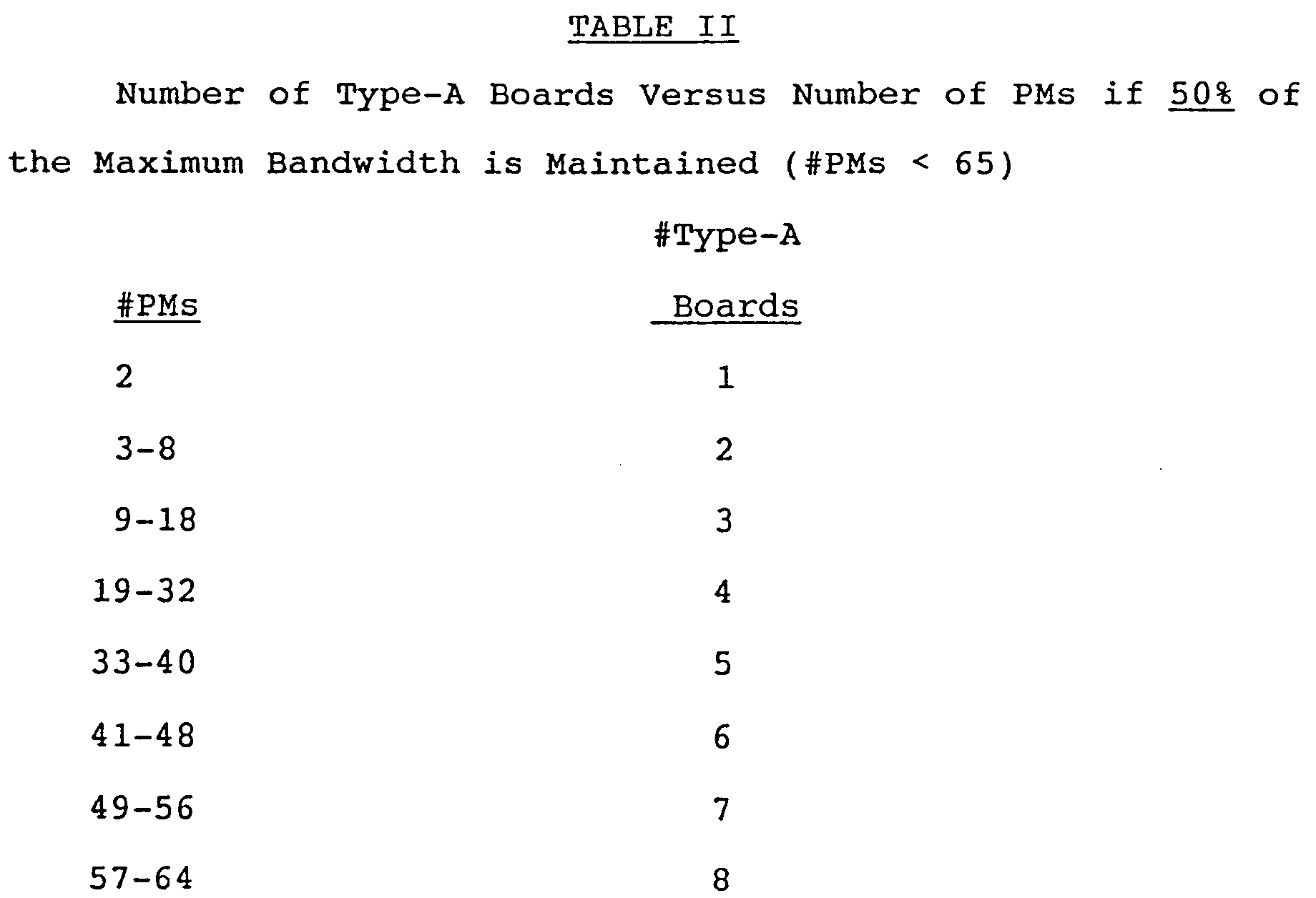


Claims (65)
- A communications system, including a multistage interconnect network (l4) comprising a plurality of interconnected active logic switch nodes (l6), characterized by diagnostic means for detecting and reporting any errors that occur within the network (l4), and for isolating the errors without propagating them; and reconfiguration means for reconfiguring the network (l4) when an error is detected, without interrupting communications in the system.
- A system according to claim l, characterized in that said reconfiguration means includes means for reconfiguring routing tables and input and output enable vectors in the network (l4), so that all communications are routed around a faulty section of the network (l4).
- A system according to claim l or 2, characterized by at least one redundant network (l4) for providing added bandwidth and fault tolerance to the system, and control means for switching between the redundant networks (l4) when a failure occurs, so that if one or more of the redundant networks (l4) is not available, another can take over.
- A method for communicating in a multistage interconnect network (l4) comprising a plurality of interconnected active logic switch nodes (l6), characterized by the steps of: detecting and reporting any errors that occur within the network (l4), and isolating the errors without propagating them, and reconfiguring the network (l4) when an error is detected, without interrupting communications in the system.
- A communications system, comprising a multistage interconnect network (l4) comprising a plurality of interconnected active logic switch nodes (l6), each switch node (l6) comprising a first plurality of input ports (36), a second plurality of output ports (38), and means for selectively connecting said input ports (36) to said output ports (38), characterized in that the multistage interconnect network (l4) comprises more than [logb N] stages of switch nodes (l6) wherein b is a total number of switch node input/output ports, N is a total number of network input/output ports (20), and [logb N] indicates a ceiling function providing the smallest integer not less than logb N, the stages thereby providing a plurality of paths between any network input port (20) and network output port (20); by diagnostic means for detecting and reporting any errors that occur within the network (l4) and by reconfiguration means for reconfiguring the network (l4), without interrupting the communications in the system, when an error is detected, and for isolating the error without propagating it.
- A system according to claim 5, characterized in that the switch nodes (l6) further comprise tag mapping table means, associated with each input port of a switch node (l6) for interpreting a routing tag to determine which output port (38) of the switch node (l6) to select in order to route correctly a connect request through the network.
- A system according to claim 6, characterized in that the tag mapping table means comprises a memory array with a plurality of entries for translating the routing tag to an output port selection, wherein the array provides a one-to-one mapping between a logical port selection provided by the routing tag and a physical port selection.
- A system according to claim 5, wherein the switch nodes (l6) further comprise input enable vectors for indicating which input ports (36) of the switch node (l6) are operational, and output enable vectors for indicating which output ports (38) of the switch node (l6) are operational.
- An apparatus for concurrently transferring messages between different ports, comprising: multistage interconnect network means (l4) for interconnecting a plurality of switch nodes (l6) for communication therebetween, each switch node (l6) comprising a first plurality of input ports (36), a second plurality of output ports (38), and means for selectively connecting said input ports (36) to said output ports (38), characterized by dynamic configuration means for determining how the switch nodes are interconnected and hence a topology of the multistage network means (l4) whereby messages can be routed correctly between the switch nodes.
- Apparatus according to claim 9, characterized in that the dynamic configuration means further comprises: means for communicating addresses between switch nodes (l6), wherein one switch node (l6) communicates its location to another switch node (l6) connected thereto; and tag mapping table means, in each switch node (l6), for storing routing information derived from the addresses of the switch nodes (l6), so that messages can be routed correctly between the switch nodes (l6).
- A apparatus according to claim 9 or l0, characterized by initializing means for querying the switch nodes (l6) at start up to determine how they are interconnected and for generating the tag mapping table means in response thereto.
- A method for communicating in a network (l4) comprising a plurality of switch nodes (l6), each switch node (l6) having a first plurality of input ports (36) a second plurality of output ports (38), and path selector means for selectively connecting the switch node input ports (36) to the switch node output ports (38), characterized by the steps of (a) interconnecting the switch nodes (l6) in a relatively arbitrary manner to effect a multistage interconnect network (l4); (b) determining how the switch nodes (l6) have been interconnected; (c) constructing routing tables for each switch node (l6) according to how the switch nodes (l6) have been interconnected; and (d) transferring messages through the network (l4) according to the routing tables, wherein each switch node (l6) that receives the messages uses a routing table to determine which output port (38) should receive the message.
- A method according to claim l2, characterized in that said determining step comprises: communicating addresses between the switch nodes (l6), so that a topology for the network (l4) can be determined; and storing routing information derived from the addresses of the switch nodes (l6), so that messages can be routed correctly through the network (l4).
- A communications system, comprising: network means (l4) for providing bidirectional data transmission between agents (l2) connected thereto, the network means comprising switch nodes (l6) connected together in a multistage interconnect network, each switch node comprising a first plurality of input ports (36), a second plurality of output ports (38), and means for selectively connecting said input ports to said output ports, characterized by self-diagnosing means, integrated with the network (l4), for detecting and reporting any errors that occur within the network (l4).
- A system according to claim l4, characterized in that the self-diagnosing means comprises diagnostic processor means (l40) for monitoring the state of the network means (l4), for performing self-tests on the components of the network means (l4), and for initializing the network means (l4) said diagnositic processor means (l40) comprising means for configuring routing tables and input and output enable vectors for the network means (l4) so that fault conditions in the network means (l4) can be bypassed.
- A system for concurrently transferring messages between different ports (20) characterized by: a plurality of switch nodes (l6), each switch node (l6) comprising a first plurality of input ports (36), a second plurality of output ports (38), and means for selectively connecting said input ports (36) to said output ports (38); means for connecting the switch nodes (l6) together in a multistage interconnect network (l4) the means for connecting comprising forward channel (32) and back channel (34) signal paths; multicast means, operative within the network (l4), for transmitting forward channel messages from a source to one or more destinations; and back channel merge means (l20), within each switch node (l6), for combining back channel replies received from the destinations into a single result, wherein the result is transmitted on the back channel (34) to the source.
- A system according to claim l6, characterized in that the multicast means comprises means for steering a multicast request for a supercluster to a bounce back point (30) within the network means (l4), wherein all multicast requests to the supercluster use the same bounce back point (30).
- A system according to claim l6 or claim l7, characterized in that the multicast means comprises means for permitting only one multicast message at a time within a supercluster, thereby preventing deadlock between competing multicast requests.
- A method for concurrently transferring messages between different ports of multistage interconnect network (l4), the network comprising a plurality of switch nodes (l6), each switch node (l6) comprising a first plurality of input ports (36), a second plurality of output ports (38), and means for selectively connecting said input ports (36) to said output ports (38), the switch nodes (l6) being connected together via forward channel (32) and back channel (34) signal paths connected to every input and output port (36,38), characterized by the steps of: (a) transmitting forward channel messages from a source to one or more destinations; and (b) combining back channel replies received from the destinations into a single result, wherein the result is transmitted on the back channel (34) to the source.
- A communications system, comprising: network means (l4) for providing bidirectional data transmission between a plurality of agents (l2) connected thereto, the network means (l4) comprising switch nodes (l6) connected together in a multistage interconnect network (l4), each switch node (l6) comprising a first plurality of input ports (36), a second plurality of output ports (38), and means for selectively connecting said input ports (36) to said output ports (38), characterized by means for arranging components within the network means (l4) and interconnections between switch nodes (l6), so that the number of agents (l2) can be increased with only a substantially linear increase in the size of the network means (l4).
- A system according to claim 20, characterized in that the means for arranging comprises: first means for constructing the network means (l4) using only a first board type (l70) when the network means (l4) contains 8 or fewer network I/O ports; second means for constructing the network means (l4) using only a first board type (l70) and a second board type (l76) when the network means (l4) contains between 9 and 64 network I/O ports; third means for constructing the network means using only a first board type (l70), a second board type (l76) and a third board type (l72) when the network means (l4) contains between 65 and 5l2 network I/O ports; and fourth means for constructing the network means (l4) using only a first board type (l70), a second board type (l76), and a fourth board type (l74) when the network means (l4) contains between 5l3 and 4096 network I/O ports.
- A system for communicating in a variety of modes between one or more transmitting agents (l2) and one or more receiving agents (l2), comprising: a multistage interconnect network (l4) intercoupling all the agents (l2) with transmit and receive lines, the network (l4) comprising a plurality of switch nodes (l6) arranged in parallel groupings in a plurality of stages within the network (l4), characterized in that the transmitting agents (l2) include means for transmitting message routing packets containing destination data designating one or more receiving agents (l2) and means for transmitting variable length data messages; and in that the switch nodes (l6) each comprise means responsive to the message routing packets for selecting node-to-node paths to one or more receiving agents (l2), wherein the switch nodes (l6) also comprise means for acknowledging receipt of a message routing packet and means for preserving the circuit connection for subsequent transmission of a variable length message.
- An active logic network (l4), comprising: a plurality of switch nodes (l6), each having a plurality of input ports (36) and a plurality of output ports (38), wherein within the switch node (l6) any input port (36) can be connected to any output port (38) and any output (38) can be connected to any input port (36); means, within each switch node (l6), for accepting a routing tag at an input port (36) identifying a destination in the network (l4); and routing determination means, within each switch node (l6), for translating the routing tag into an output port selection of the switch node (l6), thereby identifying a path to the destination.
- A network according to claim 23, characterized in that the switch node (l6) further comprises: means for accepting a connect request designating a desired destination to which a connection is requested; selector means (58), connected to the means for accepting, for selecting an output port (38) of the switch node (l6) according to the desired destination; and arbiter means (98), connected to the port selector means (58) and associated with each output port (38), for transmitting the connect request to the selected output port (38), the arbiter means (98) choosing between contending connect requests when more than one port selector means (58) is trying to access the selected output port (38) at the same time, wherein the connect request is transmitted to the selected output port (38) when it has been granted priority over the contending connect requests.
- A network according to claim 24, characterized in that the arbiter means (98) further comprises: means for servicing contending point-to-point connect requests on a "round robin" basis; and means for providing priority to multicast connect requests over point-to-point connect requests.
- A system for transmitting messages between agents (l2) selectively in (l) an arbitrary interconnection mode or (2) a multicast mode, characterized by a multistage interconnect network (l4) comprising a plurality of multiple terminal bidirectional switch nodes arrayed in a plurality of stages, the agents (l2) each including means for generating addressing messages containing destination data, including alternative descriptors for individual and multicast group designations, and each being coupled to the switch nodes (l6); and wherein the switch nodes (l6) further include means responsive to the descriptors in the addressing messages for selecting routing paths through the network (l4) and means responsive to path selection for establishing path commitments linking agents (l2) for communication of variable length messages.
- A network for communicating between agents (l2) connected thereto, characterized by packet switching means for establishing a communication path between sending and receiving agents (l2) in response to a connect request; circuit switching means for transferring messages of arbitrary length between the sending and receiving agents (l2) once the communication path has been established; pipelining means for transferring messages between sending agents and the receiving agents (l2) without waiting for the communication path to be established; back-off means for cancelling the connect request when the communication path to the receiving agent (l2) is unavailable; and retry means, triggered by the back-off means, for delaying a retry of the connect request, and for trying a different connect request from the sending agent (l2), thereby reducing contention in the network (l4).
- A communication system, characterized by: network means (l4) coupled to the agents (l2), for providing bidirectional data transmission between a plurality of agents (l2) connected thereto, the network means (l4) comprising switch nodes (l6) connected together in a multistage interconnect network, each switch node (l6) comprising a first plurality of intput ports (36), a second plurality of output ports (38), and means for selectively connecting said input ports (36) to said output ports (38); and cabling means for wiring between different stages in the network means (l4) with one or more copies of a universal wiring pattern.
- A system according to claim 28, characterized in that the universal wiring pattern comprises a permutation of switch node ports (36,38) that swaps the least significant two base b digits of a level number representation, where b is a total number of switch node input or output ports (36,38).
- A system for concurrently transferring messages between different ports (20), comprising a plurality of switch nodes (l6), each switch node comprising a first plurality of input ports (36), a second plurality of output ports (38) and means for selectively connecting the input ports (36) to the output ports (38); and means for interconnecting the switch nodes (l6) in a multistage interconnect network (l4) having a first plurality of network input ports (20) and a second plurality of network output ports (20), characterized by partitioning means for grouping the network ports (20) into logically independent subsets, wherein each subset is a supercluster; and multicast means, operative within the network (l4) for transmitting a message from a network input port (20) to one or more network output ports (20) grouped in a supercluster, wherein messages transmitted within any one supercluster are prevented from interfering with messages transmitted within any other supercluster.
- A system according to claim 30, characterized in that the partioning means further comprises: means for grouping network ports into a supercluster of size 2 m-p, wherein binary addresses for the grouped network ports are indentical in p highest order bits thereof, thereby providing 2p superclusters of size 2 m-p in the system, wherein m = [log₂ N], N is a total number of network input/output ports, and [log₂ N] indicates a ceiling function providing the smallest integer not less than log₂ N; and means for addressing each supercluster as (Ym-l, Ym-2, ...Ym-p), wherein yi ε (0,l) and m-l≦ i ≦ m-p.
- A method for concurrently transferring messages between different ports (20) of a multistage interconnect network (l4) having a plurality of interconnected switch nodes (l6) characterized by the steps of: grouping the network ports (20) into logically independent subsets, wherein each subset is a supercluster; and transmitting a message from a network input port (20) to one or more network output ports (20) grouped in a supercluster, wherein messages transmitted within any one supercluster are prevented from interfering with messages transmitted within any other supercluster.
- A method according to claim 32, characterized in that the grouping step further comprises: grouping network ports (20) into a supercluster of size 2m-p, wherein binary addresses for the grouped network ports (20) are identical in p highest order bits thereof, thereby providing 2p superclusters of size 2m-p in the system, wherein m = [log₂ N], N is a total number of network input/output ports (20), and [logb N] indicates a ceiling function providing the smallest integer not less than logb N; and addressing each supercluster as (Ym-l,Ym-2, ...,Ym-p), wherein Y i ε (0,l) and m-l ≦ i ≦ m-p.
- A communication system, comprising: network means (l4) for providing bidirectional data transmission between a plurality of agents (l2) connected thereto, the network means (l4) comprising switch nodes (l6) connected together in a multistage interconnect network (l4), each switch node (l6) comprising a first plurality of input ports (36), a second plurality of output ports (38), and means for selectively connecting said input ports (36) to said output ports (38), characterized by master clock means for supplying a master clock signal to the switch nodes (l6) throughout the network means; and controller means, coupled between the network means and the agents (l2) for communicating messages between the agent (l2) and the network means (l4), the controller means comprising clock extraction means for deriving the master clock signal transmitted throughout the network means (l4), wherein the master clock signal increments a counter in the controller means to provide a synchronous date and time of day to each agent.
- A communication system, including a network (l4) comprising at least two input ports (20) and two output ports (20), and capable of simultaneous communications between a different pair of input and output ports (20) destination for the message, and for steering the connect request to the output port (20) destination, characterized by back-off means, within the network (l4) for cancelling the connect request when the output port (20) destination is unavailable; and retry means, triggered by the back-off means, for delaying a retry of the connect request, and for trying a different connect request between the input port (20) and a different output port (20) destination, thereby reducing contention in the network (l4).
- A system according to claim 35, characterized by a plurality of switch nodes (l6), each comprising a first plurality of input ports (36), a second plurality of output ports (38), and means for selectively connecting said input ports (36) to said output ports (38); and tag mapping table means, associated with each input port (36) of a switch node (l6) to select in order to route correctly the connect request through the network (l4).
- A communication method for a network (l4) comprising at least two input ports (20) and two output ports (20), and capable of simultaneous communications between a different pair of input and output ports, characterized by the steps of: accepting a connect request containing a routing tag identifying an output port destination for the message, and steering the connect request to the output port destination; cancelling the connect request when the output port destination is unavailable; and delaying a retry of the connect request, and trying a different connect request from the input port (20), thereby reducing contention in the network (l4).
- A computer system, characterized by a plurality of processors comprising application processors (AP) for connecting external devices to the system, and access module processors (AMP) for managing access to a relational database; network means (l4), coupled to the processors (l2), for providing bidirectional data transmission between the processors (l2), the network means (l4) comprising switch nodes (l6) connected together in a multistage interconnect network, each switch node (l6) comprising a first plurality of input ports (36) to said output ports (38), the network (l4) having more than (logb N) stages of interconnected switch nodes (l6), wherein b is a total number of switch node input/output ports (36,38), N is the number of network input/output ports (20), and logb N indicates a ceiling function providing the smallest integer not less than logb N.
- A computer system according to claim 38, characterized in that the AP further comprises one or more microprocessors, including memory and at least two connections to the network (l4), for executing an independent copy of the operating system and maintaining an independent address space.
- A communication systems, including a network (l4) comprising a plurality of interconnected switch nodes (l6), characterized by identification means for communicating a unique identifier to each agent (l2) attached to the network (l4), so that an agent (l2) can be connected to any available port (20) of the network (l4) and determine its address therein, thereby simplifying installation.
- A system according to claim 40, characterized in that the identification means comprises means for determining the agent's address within the network (l4) using a level number associated with the port (20) to which it is connected, said means for determining comprising means for transmitting a command to the network (l4), wherein a switch node (l6) that receives the command replies thereto with a port address.
- A communications apparatus, including a plurality of switch nodes (l6) arranged and interconnected into a multistage interconnect network (l4), characterized by error testing means for generating test patterns during data transmission through the network (l4), the error testing means comprising means, within each switch node (l6), for inverting parity on the data transmission so that a receiving switch node (l6) reports an error.
- Apparatus according to claim 42, characterized in that the error testing means further comprises means for forwarding a test command to the receiving switch node (l6) and means for inverting parity on data which follows the test command.
- A switch node (l6) providing for the simultaneous interconnection of multiple messages, characterized by means defining a plurality of input and output ports (36,38); means for selectively connecting any input port (36) to either any one output port (38), or a predetermined number of the output ports (38), or all of the output ports (38); and error testing means for generating test patterns to test data transmission on the input and output ports (36,38), the error testing means comprising means for inverting parity on the data transmission so that a switch node (l6) receiving the data transmission reports an error.
- A switch node according to claim 44, characterized in that the error testing means further comprises means for forwarding a test command to the receiving switch node (l6) and means for inverting parity on data which follows the test command.
- A switch node (l6) for use in a network (l4) having a plurality of similar nodes (l6) interconnected by cabling, for simultaneous interconnection of multiple messages of different types, including message routing packets, characterized by: means defining a plurality of input and output terminals (36,38); means for storing reconfigurable mapping data which identifies available interconnection paths using the input and output terminals (36,38); and means, coupled to the means for storing, for arbitrarily interconnecting any input with any one output, a predetermined number of the outputs or all the outputs.
- A switch node (l6) according to claim 46, characterized in that the means for storing reconfigurable mapping data further comprises means for storing input and output enable vectors indicating which terminals (36,38) are operational.
- A switch node (l6) according to claim 46 or claim 47, characterized in that the switch nodes (l6) each include forward channel and back channel signal paths (32,24) coupled to each of the input and output ports (36,38) in each of the switch nodes (l6), wherein the back channel signal paths (34) have a narrower bandwidth relative to the forward channel signal paths (32) and by means for synchronously combining replies from the back channels (34) so that replies are sorted as they propogate through the switch node (l6), wherein only the reply having a highest priority is transmitted to the next switch node (l6) on the back channel (34).
- A communications network comprising: a plurality of switch nodes (l6) arranged into a multistage interconnect network (l4) having a plurality of input and output ports (20), each port (20) being coupled to an agent (l2) to effect communication between agents through the network characterized by the network (l4) having a multiple of [logb N] stages of interconnected switch nodes (l6), wherein b is a total number of switch node input/output ports (36,38), N is the number of network I/O ports (20), and [logb N] indicates a ceiling function providing the smallest integer not less than logb N, thereby providing additional paths between any network input port (20) and network output port (20) to enhance fault tolerance and lessen contention; and the network (l4) having a loop-back point (30) indicating where the stages of the network (l4) are physical folded together so that corresponding switch nodes (l6) in similarly numbered stages on either side of the loop-back point (30) are located adjacent to each other, thereby simplifying packaging and minimizing signal path lengths.
- A system for concurrently transferring messages, comprising: a multistage interconnect network (l4) comprising a plurality of interconnected active logic switch nodes (l6); each switch node (l6) comprising a first plurality of input ports (36), a second plurality of output ports (38), and means for selectively connecting said input ports (36) to said output ports (38), characterized by the multistage interconnect network (l4) comprising more than [logb N] stages of switch nodes (l6), wherein b is a total number of switch node input/output ports (36,38), N is a total number of network input/output ports (20), and [logb N] indicates a ceiling function providing the smallest integer not less than logb N, the multistage interconnect network (l4) providing a plurality of paths between any network input port (20) and network output port (20) to enhance fault tolerance and lessen contention; and multicast steering means, within each switch node (l6), for routing multicast requests to a specific input port (36) of a specific switch node (l6) within the network (l4), so that only one multicast request can occur at a time, thereby preventing deadlock between competing multicast requests.
- A system according to claim 50, characterized by means for storing a reply from each network output port (20) in a back channel (34); and means for collecting replies from the network output ports (20) and for applying the replies to merge means for synchronously combining all of the replies, wherein the replies are sorted as they propagate through the merge means, so that only the reply having the highest priority is transmitted through the system.
- Apparatus for concurrently transferring messages between different ports (20), including a multistage interconnect network (l4) comprising a plurality of interconnected active logic switch nodes (l6); each switch node (l6) comprising a first plurality of input ports (36), a second plurality of output ports (38), and means for selectively connecting said input ports to said output ports, characterized by the multistage interconnect network (l4) comprising more than [logb N] stages of switch nodes (l6), wherein b is a total number of switch node input/output ports (36,38) N is a total number of network input ports and network output ports (20), and [logb N] indicates a ceiling function providing the smallest integer not less than logb N, the multistage interconnect network providing a plurality of paths between any network input port (20) and network output port (20) to enhance fault tolerance and lessen contention; and deadlock avoidance means, within each switch node (l6), for allowing only one routing multicast request at a time, thereby preventing deadlock between requests.
- A communications system, including a plurality of switch nodes (l6) arranged into a multistage interconnect network (l4) having a plurality of input and output ports (20), each port (20) being coupled to an agent (l2) to effect communication between agents (l2) through the network, characterized by the network (l4) having more than [logb N] stages of interconnected switch nodes (l6), wherein b is a total number of switch node input/output ports (36,38), N is the number of network input/output ports (20), and [logb N] indicates a ceiling function providing the smallest integer not less than logb N; and the network (l4) having a plurality of turnaround points (30) at the highest stage of switch nodes (l6), the turnaround points (30) logically differentiating between switch nodes (l6) that load balance messages through the network (l4) from the switch nodes that direct messages to receiving agents (l2) means for depopulating switch nodes (l6) from the highest stage to reduce the number of turnaround points (30) in the network (l4), as long as at least one path exists between every network input port (20) and every network output port (20); and the input and output ports (36,38) of the switch nodes (l6) in stages adjacent the highest stage sensing when the switch nodes (l6) in the highest stage are removed and disabling the input and output ports (20) in response thereto, thereby lowering the bandwidth of the network (l4) and lowering the cost of the network without a loss of functionality.
- A communications system, including a plurality of switch nodes (l6), each switch node (l6) comprising a first plurality of input ports (36), a second plurality of output ports (38), and means for selectively connecting said input ports (36) to said output ports (38); and means for interconnecting the switch nodes (l6) together in a multistage interconnect network (l4) to simplify the cabling therebetween, wherein a pattern of interconnections between different stages of switch nodes (l6) is specified by permuting the digits of the level number representing a port of a switch node.
- A system according to claim 54, characterized in that the means for interconnecting comprises means for connecting switch node ports identified by (S : xn-l...xlx₀) to switch node ports (36,38) identified by (S+l : PERMUTE

- A communications apparatus, comprising: a multistage interconnect network (l4) comprising a plurality of interconnected active logic switch nodes (l6), each switch node (l6) comprising a first plurality of input ports (36), a second plurality of output ports (38), and means for selectively connecting said input ports (36) to said output ports (38), characterized by the multistage interconnect network (l4) comprising more than [logb N] stages of switch nodes (l6), wherein b is a total number of switch node input/output ports (36,38), N is a total number of network input/output ports (20), and [logb N] indicates a ceiling function providing the smallest integer not less than logb N, thereby providing a plurality of paths between any network input port (20) and network output port (20) to enhance fault tolerance and lessen contention; and load balancing means, in each switch node (l6), for distributing messages among the plurality of output ports (20) so that messages are evenly distributed throughout the network (l4).
- Apparatus according to claim 56, characterized in that said load balancing means comprises: means, within each switch node (l6), for choosing a switch node output port (38) similarly numbered as a requesting switch node input port (36) when the similarly numbered switch node output port is available; and means, within each switch node (l6), for choosing a next available switch node output port (38) when the similarly numbered switch node output port (38) is not available.
- A communication system, comprising: a plurality of switch nodes (l6), each switch node (l6) comprising a first plurality of input ports (36), a second plurality of output ports (38), and means for selectively connecting said input ports (36) to said output ports (38), characterized by means for connecting the switch nodes (l6) together in a multistage interconnect network (l4), the means for connecting comprising forward channel (32) and back channel (34) signal paths coupled to each of the input (36) and output (38) ports in the switch nodes (l6), wherein the back channel signal paths (34) have a narrower bandwidth relative to the forward channel signal paths (32).
- A system according to claim 58, characterized by multicast means, operative within the network (l4), for transmitting forward channel messages from a source to one or more destinations; and back channel merge means (l20), within each switch node, for combining back channel replies received from the destinations into a single result, wherein the result is transmitted on the back channel (34) to the source.
- A method of communicating among a plurality of switch nodes (l6) connected together in a multistage interconnect network (l4), each switch node comprising a first plurality of input ports (36), a second plurality of output ports (38), and means for selectively connecting said input ports (36) to said output ports (38), characterized by the steps of:
transmitting messages between switch nodes (l6) using a forward channel (32) coupled to each of the input and output ports in the switch nodes (l6); and transmitting between switch nodes (l6) using a back channel (34) coupled to each of the input and output ports (36,38) in the switch nodes (l6), wherein the back channels (34) have a narrower bandwidth relative to the forward channels (32) to simplify packaging. - A method according to claim 60, characterized by the steps of transmitting forward channel messages from a source to one or more destinations; and combining back channel replies received from the destinations into a single result, wherein the result is transmitted on the back channel (34) to the source.
- A communications apparatus, including multistage interconnect network means (l4) for interconnecting a plurality of switch nodes (l6) for communication therebetween; dynamic configuration means for determining how the switch nodes (l6) are interconnected by the multistage interconnect network means (l4); and means for remapping connections between the switch nodes so that all connections in a backplane connecting the switch nodes are horizontal.
- A multiprocessor system, including a plurality of processors (l2) and a network (l4) for interconnecting the processors (l2), characterized in that the network (l4) comprises a plurality of bounce-back points (30) for directing the transmission of messages through the network (l4), and means for communicating between processors (l2) through the network (l4) via the bounce-back points (30).
- A multiprocessor according to claim 63, characterized in that said network (l4) comprises: a plurality of switch nodes (l6) arranged into a multistage interconnect network (l4) having a plurality of input and output ports (20), each port (20) being coupled to an agent (l2) to effect communication between agents (l2) through the network (l4); the multistage interconnect network (l4) comprising more than [logb N] stages of switch nodes (l6), wherein b is a total number of switch node input/output ports (36,38), N is a total number of network input/output ports (20), and [logb N] indicates a ceiling function providing the smallest integer not less than logb N, the multistage interconnect network (l4) providing a plurality of paths between any network input port (20) and network output port (20) to enhance fault tolerance and lessen contention; and the network (l4) having a plurality of bounce-back points (30) at the highest stage of switch nodes (l6), the bounce-back points (30) logically differentiating between switch nodes (l6) that load balance messages through the network (l4) from switch nodes (l6) that direct messages to receiving agents (l2).
- A multiprocessor system, including a plurality of processors (l2) and a network for connecting the processors (l2), characterized in that said network (l4) has a plurality of bounce-back points (30) for directing the transmission of messages through the network (l4); and means for partitioning the processors (l2) into one or more superculsters comprising logically independent subsets of processors (l2); and by means for multicast communicating within superclusters by steering a multicast message to a particular bounce-back point (30) in the network for subsequent routing to the processors (l2) in the supercluster, thereby preventing deadlock in the network (l4) by permitting only one multicast message through the particularly bounce-back point (30) at a time and preventing multicast messages to different superclusters from interfering with each other.
Applications Claiming Priority (2)
| Application Number | Priority Date | Filing Date | Title |
|---|---|---|---|
| US07/694,110 US5321813A (en) | 1991-05-01 | 1991-05-01 | Reconfigurable, fault tolerant, multistage interconnect network and protocol |
| US694110 | 1991-05-01 |
Publications (3)
| Publication Number | Publication Date |
|---|---|
| EP0511834A2 true EP0511834A2 (en) | 1992-11-04 |
| EP0511834A3 EP0511834A3 (en) | 1999-04-07 |
| EP0511834B1 EP0511834B1 (en) | 2002-11-27 |
Family
ID=24787438
Family Applications (1)
| Application Number | Title | Priority Date | Filing Date |
|---|---|---|---|
| EP92303833A Expired - Lifetime EP0511834B1 (en) | 1991-05-01 | 1992-04-28 | Multi-stage interconnect network for processing system |
Country Status (4)
| Country | Link |
|---|---|
| US (7) | US5321813A (en) |
| EP (1) | EP0511834B1 (en) |
| JP (1) | JPH05207011A (en) |
| DE (1) | DE69232857T2 (en) |
Cited By (7)
| Publication number | Priority date | Publication date | Assignee | Title |
|---|---|---|---|---|
| EP0600581A2 (en) * | 1992-11-30 | 1994-06-08 | Fujitsu Limited | Multiprocessor system transferring abnormality detection signal generated in networking apparatus back to processor in parallel with data transfer route |
| EP0632913A1 (en) * | 1992-03-25 | 1995-01-11 | Encore Computer U.S., Inc. | Fiber optic memory coupling system |
| FR2820921A1 (en) * | 2001-02-14 | 2002-08-16 | Canon Kk | DEVICE AND METHOD FOR TRANSMISSION IN A SWITCH |
| WO2004092955A2 (en) * | 2003-04-17 | 2004-10-28 | Sun Microsystems, Inc. | Error management |
| EP1926259B1 (en) * | 2006-11-21 | 2016-01-27 | EMC Corporation | Control of communication ports of computing devices using policy-based decisions |
| EP3057334A1 (en) * | 2015-02-16 | 2016-08-17 | Juniper Networks, Inc. | Multi-stage switch fabric fault detection and handling |
| US10951527B2 (en) | 2018-12-28 | 2021-03-16 | Juniper Networks, Inc. | Switch fabric packet flow reordering |
Families Citing this family (368)
| Publication number | Priority date | Publication date | Assignee | Title |
|---|---|---|---|---|
| US5612953A (en) * | 1991-02-22 | 1997-03-18 | International Business Machines Corporation | Multi-media serial line switching adapter for parallel networks and heterogeneous and homologous computer systems |
| US5404461A (en) * | 1991-03-29 | 1995-04-04 | International Business Machines Corp. | Broadcast/switching apparatus for executing broadcast/multi-cast transfers over unbuffered asynchronous switching networks |
| US5825773A (en) * | 1991-03-20 | 1998-10-20 | Hitachi, Ltd. | Switching system for transferring broadcast packet held in broadcast buffer received from input port to output ports according to the state of each output port |
| US5321813A (en) | 1991-05-01 | 1994-06-14 | Teradata Corporation | Reconfigurable, fault tolerant, multistage interconnect network and protocol |
| JPH05152608A (en) * | 1991-06-29 | 1993-06-18 | Toshiba Corp | Optical element and optical bus, and optical interprocessor coupled network using them |
| JP3679813B2 (en) * | 1991-07-22 | 2005-08-03 | 株式会社日立製作所 | Parallel computer |
| US5742779A (en) * | 1991-11-14 | 1998-04-21 | Tolfa Corporation | Method of communication using sized icons, text, and audio |
| US5758053A (en) * | 1992-07-22 | 1998-05-26 | Hitachi, Ltd. | Fault handling and recovery for system having plural processors |
| AU4798793A (en) * | 1992-08-10 | 1994-03-03 | Monolithic System Technology, Inc. | Fault-tolerant, high-speed bus system and bus interface for wafer-scale integration |
| US5694547A (en) * | 1992-10-13 | 1997-12-02 | Bay Networks, Inc. | System for registration of clients in an ATM network providing for communication of client registration messages to a central manager |
| US5715396A (en) * | 1992-10-13 | 1998-02-03 | Bay Networks, Inc. | Method for providing for automatic topology discovery in an ATM network or the like |
| US6415271B1 (en) | 1993-02-10 | 2002-07-02 | Gm Network Limited | Electronic cash eliminating payment risk |
| US5983207A (en) * | 1993-02-10 | 1999-11-09 | Turk; James J. | Electronic cash eliminating payment risk |
| US5623698A (en) * | 1993-04-30 | 1997-04-22 | Cray Research, Inc. | Memory interconnect network having separate routing networks for inputs and outputs using switches with FIFO queues and message steering bits |
| JPH0779233A (en) * | 1993-06-29 | 1995-03-20 | Synoptics Commun Inc | Apparatus for establishing topology, method and apparatus for communicating topology information |
| CA2117506C (en) * | 1993-08-19 | 2000-10-10 | Minoru Oda | Return address adding mechanism for use in parallel processing system |
| US5450425A (en) * | 1993-11-19 | 1995-09-12 | Multi-Tech Systems, Inc. | Protocol for communication of a data packet |
| US5630129A (en) * | 1993-12-01 | 1997-05-13 | Sandia Corporation | Dynamic load balancing of applications |
| EP0660239A1 (en) * | 1993-12-17 | 1995-06-28 | International Business Machines Corporation | Data transfer between computing elements |
| DE69519426T2 (en) * | 1994-03-22 | 2001-06-21 | Hyperchip Inc | Cell-based fault-tolerant architecture with advantageous use of the unallocated redundant cells |
| US5835755A (en) * | 1994-04-04 | 1998-11-10 | At&T Global Information Solutions Company | Multi-processor computer system for operating parallel client/server database processes |
| US5708772A (en) * | 1994-04-29 | 1998-01-13 | Bay Networks, Inc. | Network topology determination by dissecting unitary connections and detecting non-responsive nodes |
| US5619656A (en) * | 1994-05-05 | 1997-04-08 | Openservice, Inc. | System for uninterruptively displaying only relevant and non-redundant alert message of the highest severity for specific condition associated with group of computers being managed |
| US5671222A (en) * | 1994-06-06 | 1997-09-23 | Lucent Technologies Inc. | Multicast routing in self-routing multistage networks |
| US5655149A (en) * | 1994-06-10 | 1997-08-05 | Harris Corporation | System for identifying a primary processor and non-primary processors after system reboot independent of processor positions and without using default primary processor identification |
| US5577172A (en) * | 1994-07-01 | 1996-11-19 | Lasermaster Corporation | High-capacity protocol for packet-based networks |
| US6091507A (en) | 1994-07-01 | 2000-07-18 | Colorspan Corporation | Method and apparatus for printing a document over a network |
| US5751967A (en) * | 1994-07-25 | 1998-05-12 | Bay Networks Group, Inc. | Method and apparatus for automatically configuring a network device to support a virtual network |
| US5724517A (en) * | 1994-09-27 | 1998-03-03 | International Business Machines Corporation | Method for generating a topology map for a serial bus |
| US5603044A (en) * | 1995-02-08 | 1997-02-11 | International Business Machines Corporation | Interconnection network for a multi-nodal data processing system which exhibits incremental scalability |
| JPH08263463A (en) * | 1995-03-20 | 1996-10-11 | Fujitsu Ltd | Initial diagnosis of device and method for processor |
| JPH08329021A (en) * | 1995-03-30 | 1996-12-13 | Mitsubishi Electric Corp | Client server system |
| KR100236820B1 (en) * | 1995-05-08 | 2000-01-15 | 이계철 | Method and system of predicting point-to-point traffic |
| US5636371A (en) * | 1995-06-07 | 1997-06-03 | Bull Hn Information Systems Inc. | Virtual network mechanism to access well known port application programs running on a single host system |
| US5907418A (en) * | 1995-08-09 | 1999-05-25 | Motorola, Inc. | Apparatus for infrared channel and method therefor |
| US6108704A (en) * | 1995-09-25 | 2000-08-22 | Netspeak Corporation | Point-to-point internet protocol |
| US6185184B1 (en) | 1995-09-25 | 2001-02-06 | Netspeak Corporation | Directory server for providing dynamically assigned network protocol addresses |
| US6226678B1 (en) | 1995-09-25 | 2001-05-01 | Netspeak Corporation | Method and apparatus for dynamically defining data communication utilities |
| US6009469A (en) * | 1995-09-25 | 1999-12-28 | Netspeak Corporation | Graphic user interface for internet telephony application |
| US5805578A (en) * | 1995-10-27 | 1998-09-08 | International Business Machines Corporation | Automatic reconfiguration of multipoint communication channels |
| US5710547A (en) * | 1995-12-08 | 1998-01-20 | Motorola, Inc. | Selective call transceiver and method of re-registering same |
| US5761657A (en) * | 1995-12-21 | 1998-06-02 | Ncr Corporation | Global optimization of correlated subqueries and exists predicates |
| US5914798A (en) * | 1995-12-29 | 1999-06-22 | Mci Communications Corporation | Restoration systems for an optical telecommunications network |
| US6199172B1 (en) * | 1996-02-06 | 2001-03-06 | Cabletron Systems, Inc. | Method and apparatus for testing the responsiveness of a network device |
| US5764634A (en) * | 1996-03-13 | 1998-06-09 | International Business Machines Corporation | Lan switch with zero latency |
| US5828847A (en) * | 1996-04-19 | 1998-10-27 | Storage Technology Corporation | Dynamic server switching for maximum server availability and load balancing |
| US5727142A (en) * | 1996-05-03 | 1998-03-10 | International Business Machines Corporation | Method for a non-disruptive host connection switch after detection of an error condition or during a host outage or failure |
| US5748959A (en) * | 1996-05-24 | 1998-05-05 | International Business Machines Corporation | Method of conducting asynchronous distributed collective operations |
| US5862340A (en) * | 1996-05-24 | 1999-01-19 | International Business Machines Corporation | Method operating in each node of a computer system providing and utilizing special records for collective communication commands to increase work efficiency at each node |
| US5758161A (en) * | 1996-05-24 | 1998-05-26 | International Business Machines Corporation | Testing method for checking the completion of asynchronous distributed collective operations |
| US5881241A (en) * | 1996-06-19 | 1999-03-09 | Sun Microsystems, Inc. | System for transmitting data packet after matching data packet's routing pattern with predetermined data routes stored in a route table |
| US5781546A (en) * | 1996-06-25 | 1998-07-14 | International Business Machines Corporation | Route restrictions for deadlock free routing with increased bandwidth in a multi-stage cross point packet switch |
| US5812549A (en) * | 1996-06-25 | 1998-09-22 | International Business Machines Corporation | Route restrictions for deadlock free routing with increased bandwidth in a multi-stage cross point packet switch |
| EP1010294A1 (en) * | 1996-10-29 | 2000-06-21 | Lecroy Corporation | Computer network cross-connect panel providing physical layer monitoring |
| KR100210806B1 (en) * | 1996-12-10 | 1999-07-15 | 유기범 | Method for initializing node address of ipc |
| US6212649B1 (en) | 1996-12-30 | 2001-04-03 | Sentar, Inc. | System and method for providing highly-reliable coordination of intelligent agents in a distributed computing system |
| US5968189A (en) * | 1997-04-08 | 1999-10-19 | International Business Machines Corporation | System of reporting errors by a hardware element of a distributed computer system |
| US6115378A (en) * | 1997-06-30 | 2000-09-05 | Sun Microsystems, Inc. | Multi-layer distributed network element |
| US6088356A (en) | 1997-06-30 | 2000-07-11 | Sun Microsystems, Inc. | System and method for a multi-layer network element |
| US6246680B1 (en) * | 1997-06-30 | 2001-06-12 | Sun Microsystems, Inc. | Highly integrated multi-layer switch element architecture |
| US6081522A (en) | 1997-06-30 | 2000-06-27 | Sun Microsystems, Inc. | System and method for a multi-layer network element |
| US6044418A (en) | 1997-06-30 | 2000-03-28 | Sun Microsystems, Inc. | Method and apparatus for dynamically resizing queues utilizing programmable partition pointers |
| US6044087A (en) | 1997-06-30 | 2000-03-28 | Sun Microsystems, Inc. | Interface for a highly integrated ethernet network element |
| US6081512A (en) | 1997-06-30 | 2000-06-27 | Sun Microsystems, Inc. | Spanning tree support in a high performance network device |
| US6094435A (en) | 1997-06-30 | 2000-07-25 | Sun Microsystems, Inc. | System and method for a quality of service in a multi-layer network element |
| US5884090A (en) * | 1997-07-17 | 1999-03-16 | International Business Machines Corporation | Method and apparatus for partitioning an interconnection medium in a partitioned multiprocessor computer system |
| US6009264A (en) * | 1997-08-28 | 1999-12-28 | Ncr Corporation | Node coordination using a channel object and point-to-point protocol |
| US6308207B1 (en) * | 1997-09-09 | 2001-10-23 | Ncr Corporation | Distributed service subsystem architecture for distributed network management |
| US6088330A (en) * | 1997-09-09 | 2000-07-11 | Bruck; Joshua | Reliable array of distributed computing nodes |
| US6285659B1 (en) * | 1997-09-10 | 2001-09-04 | Level One Communications, Inc. | Automatic protocol selection mechanism |
| US6052360A (en) * | 1997-10-23 | 2000-04-18 | Mci Communications Corporation | Network restoration plan regeneration responsive to transitory conditions likely to affect network traffic |
| US6216132B1 (en) | 1997-11-20 | 2001-04-10 | International Business Machines Corporation | Method and system for matching consumers to events |
| US6091724A (en) * | 1997-11-20 | 2000-07-18 | International Business Machines Corporation | Routing messages within a network using the data content of the message |
| US6081906A (en) * | 1997-11-21 | 2000-06-27 | Fuji Xerox Co., Ltd. | Multi-thread processing with queuing and recovery |
| US6256740B1 (en) * | 1998-02-06 | 2001-07-03 | Ncr Corporation | Name service for multinode system segmented into I/O and compute nodes, generating guid at I/O node and exporting guid to compute nodes via interconnect fabric |
| US6078990A (en) * | 1998-02-06 | 2000-06-20 | Ncr Corporation | Volume set configuration using a single operational view |
| US6247077B1 (en) * | 1998-02-06 | 2001-06-12 | Ncr Corporation | Highly-scalable parallel processing computer system architecture |
| US6148349A (en) * | 1998-02-06 | 2000-11-14 | Ncr Corporation | Dynamic and consistent naming of fabric attached storage by a file system on a compute node storing information mapping API system I/O calls for data objects with a globally unique identification |
| US6081812A (en) * | 1998-02-06 | 2000-06-27 | Ncr Corporation | Identifying at-risk components in systems with redundant components |
| US6105122A (en) * | 1998-02-06 | 2000-08-15 | Ncr Corporation | I/O protocol for highly configurable multi-node processing system |
| JPH11259423A (en) * | 1998-03-10 | 1999-09-24 | Fujitsu Ltd | Security system for transmitting device |
| US6205532B1 (en) | 1998-05-22 | 2001-03-20 | Avici Systems, Inc. | Apparatus and methods for connecting modules using remote switching |
| US6549932B1 (en) * | 1998-06-03 | 2003-04-15 | International Business Machines Corporation | System, method and computer program product for discovery in a distributed computing environment |
| US6553403B1 (en) * | 1998-06-03 | 2003-04-22 | International Business Machines Corporation | System, method and computer program product for monitoring in a distributed computing environment |
| US6460070B1 (en) | 1998-06-03 | 2002-10-01 | International Business Machines Corporation | Mobile agents for fault diagnosis and correction in a distributed computer environment |
| US6421711B1 (en) * | 1998-06-29 | 2002-07-16 | Emc Corporation | Virtual ports for data transferring of a data storage system |
| US6247143B1 (en) * | 1998-06-30 | 2001-06-12 | Sun Microsystems, Inc. | I/O handling for a multiprocessor computer system |
| US6484155B1 (en) | 1998-07-21 | 2002-11-19 | Sentar, Inc. | Knowledge management system for performing dynamic distributed problem solving |
| US6233073B1 (en) | 1998-07-30 | 2001-05-15 | International Business Machines Corporation | Diagnostic injection of transmission errors in fiber optic networks |
| US20020085547A1 (en) * | 1998-09-17 | 2002-07-04 | Mcnamara Tod W. | High density network topology |
| EP1114542B1 (en) * | 1998-09-18 | 2008-03-12 | Harris Corporation | Distributed trunking mechanism for a vhf network |
| US6587943B1 (en) * | 1998-12-03 | 2003-07-01 | Nortel Networks Ltd. | Apparatus and method for limiting unauthorized access to a network multicast |
| US6473827B2 (en) * | 1998-12-22 | 2002-10-29 | Ncr Corporation | Distributed multi-fabric interconnect |
| US6885661B1 (en) | 1998-12-30 | 2005-04-26 | Nortel Networks Limited | Private branch exchange built using an ATM Network |
| US6804229B2 (en) * | 1998-12-30 | 2004-10-12 | Nortel Networks Limited | Multiple node network architecture |
| US6788703B2 (en) | 1998-12-30 | 2004-09-07 | Nortel Networks Limited | DS0 on ATM, mapping and handling |
| US6778538B2 (en) | 1998-12-30 | 2004-08-17 | Nortel Networks Limited | Virtual junctors |
| US6768736B1 (en) | 1998-12-30 | 2004-07-27 | Nortel Networks Limited | Using an ATM switch to grow the capacity of a switching stage |
| US7216348B1 (en) | 1999-01-05 | 2007-05-08 | Net2Phone, Inc. | Method and apparatus for dynamically balancing call flow workloads in a telecommunications system |
| US7283463B2 (en) | 1999-03-30 | 2007-10-16 | International Business Machines Corporation | Non-disruptive reconfiguration of a publish/subscribe system |
| US7050432B1 (en) | 1999-03-30 | 2006-05-23 | International Busines Machines Corporation | Message logging for reliable multicasting across a routing network |
| US6907011B1 (en) | 1999-03-30 | 2005-06-14 | International Business Machines Corporation | Quiescent reconfiguration of a routing network |
| US6889254B1 (en) | 1999-03-30 | 2005-05-03 | International Business Machines Corporation | Scalable merge technique for information retrieval across a distributed network |
| US6760340B1 (en) | 1999-03-30 | 2004-07-06 | International Business Machines Corporation | Message sequencing for ordered multicasting of a message across a routing network |
| US6760331B1 (en) * | 1999-03-31 | 2004-07-06 | Cisco Technology, Inc. | Multicast routing with nearest queue first allocation and dynamic and static vector quantization |
| US6931440B1 (en) * | 1999-04-21 | 2005-08-16 | Emc Corporation | Method and apparatus for dynamically determining whether access to a resource connected to a computer has changed and determining how to access the resource with a new identifier |
| JP3699863B2 (en) * | 1999-07-12 | 2005-09-28 | 株式会社日立コミュニケーションテクノロジー | Error correction code apparatus, error correction code decoding apparatus, and transmission apparatus |
| US6392990B1 (en) | 1999-07-23 | 2002-05-21 | Glenayre Electronics, Inc. | Method for implementing interface redundancy in a computer network |
| FR2798755B1 (en) * | 1999-09-16 | 2001-11-02 | Bull Sa | ADMINISTRATION SYSTEM FOR MULTIMODULAR MULTIPROCESSOR MACHINES |
| US6578086B1 (en) | 1999-09-27 | 2003-06-10 | Nortel Networks Limited | Dynamically managing the topology of a data network |
| SE513215C2 (en) * | 1999-10-18 | 2000-07-31 | Telia Ab | Apparatus for signal coupling between fiber optic conductors and method for configuring optical cross couplers |
| US6615272B1 (en) * | 1999-10-20 | 2003-09-02 | Lantronix, Inc. | Switch node for connecting a keyboard video mouse to selected servers in a interconnected switch node network |
| US6499115B1 (en) * | 1999-10-22 | 2002-12-24 | Dell Usa, L.P. | Burn rack dynamic virtual local area network |
| US6418526B1 (en) | 1999-11-15 | 2002-07-09 | Ncr Corporation | Method and apparatus for synchronizing nodes in massively parallel systems |
| US6745240B1 (en) | 1999-11-15 | 2004-06-01 | Ncr Corporation | Method and apparatus for configuring massively parallel systems |
| US6519697B1 (en) | 1999-11-15 | 2003-02-11 | Ncr Corporation | Method and apparatus for coordinating the configuration of massively parallel systems |
| US6412002B1 (en) | 1999-11-15 | 2002-06-25 | Ncr Corporation | Method and apparatus for selecting nodes in configuring massively parallel systems |
| US6625148B1 (en) * | 1999-11-18 | 2003-09-23 | 3Com Corporation | Self routing interconnect cross-switch |
| US7102999B1 (en) * | 1999-11-24 | 2006-09-05 | Juniper Networks, Inc. | Switching device |
| JP3498666B2 (en) | 2000-02-28 | 2004-02-16 | 日本電気株式会社 | Data transfer device, data transfer system, data transfer method, and storage medium |
| US6728715B1 (en) | 2000-03-30 | 2004-04-27 | International Business Machines Corporation | Method and system for matching consumers to events employing content-based multicast routing using approximate groups |
| US7301941B2 (en) * | 2000-04-11 | 2007-11-27 | Lsi Corporation | Multistage digital cross connect with synchronized configuration switching |
| US20030058848A1 (en) * | 2000-04-11 | 2003-03-27 | Velio Communications, Inc. | Scheduling clos networks |
| US6792559B1 (en) | 2000-04-25 | 2004-09-14 | Ncr Corporation | Performing operations in an environment recreated from system dump information |
| US6591311B1 (en) | 2000-04-27 | 2003-07-08 | Rockwell Automation Technologies, Inc. | Method and system for selecting controller output value source |
| US6701214B1 (en) * | 2000-04-27 | 2004-03-02 | Rockwell Automation Technologies, Inc. | Driver board control system for modular conveyer with address-based network for inter-conveyor communication |
| US6745232B1 (en) | 2000-08-23 | 2004-06-01 | Rockwell Automation Technologies, Inc. | Strobed synchronization providing diagnostics in a distributed system |
| US6701462B1 (en) | 2000-05-19 | 2004-03-02 | Rockwell Automation Technologies, Inc. | Situational aware output configuration and execution |
| US6643802B1 (en) | 2000-04-27 | 2003-11-04 | Ncr Corporation | Coordinated multinode dump collection in response to a fault |
| US7106728B1 (en) | 2000-05-01 | 2006-09-12 | Industrial Technology Research Institute | Switching by multistage interconnection of concentrators |
| US6885644B1 (en) * | 2000-05-30 | 2005-04-26 | International Business Machines Corporation | Topology propagation in a distributed computing environment with no topology message traffic in steady state |
| US7685602B1 (en) | 2000-06-05 | 2010-03-23 | Teradata Us, Inc. | Controlling software components in a multi-node processing system |
| US6539338B1 (en) * | 2000-06-09 | 2003-03-25 | 3Com Corporation | Self-diagnostic testing of a network interface adapter |
| US6591285B1 (en) | 2000-06-16 | 2003-07-08 | Shuo-Yen Robert Li | Running-sum adder networks determined by recursive construction of multi-stage networks |
| US6522825B1 (en) * | 2000-06-30 | 2003-02-18 | Intel Corporation | Optical-to-electrical conversion on rear-panel transition cards |
| US7246111B1 (en) | 2000-06-30 | 2007-07-17 | Ncr Corporation | Capturing database system information |
| US6738756B1 (en) | 2000-06-30 | 2004-05-18 | Ncr Corporation | Analysis method and apparatus for a parallel system |
| US20020093952A1 (en) * | 2000-06-30 | 2002-07-18 | Gonda Rumi Sheryar | Method for managing circuits in a multistage cross connect |
| US7185000B1 (en) | 2000-06-30 | 2007-02-27 | Ncr Corp. | Method and apparatus for presenting query plans |
| US6804193B1 (en) * | 2000-07-28 | 2004-10-12 | Marconi Intellectual Property (Ringfence) Inc. | Protected Ethernet backplane communication |
| US7085493B2 (en) * | 2000-08-23 | 2006-08-01 | Nec Corporation | Line processing equipment |
| US6804819B1 (en) | 2000-09-18 | 2004-10-12 | Hewlett-Packard Development Company, L.P. | Method, system, and computer program product for a data propagation platform and applications of same |
| US6977927B1 (en) | 2000-09-18 | 2005-12-20 | Hewlett-Packard Development Company, L.P. | Method and system of allocating storage resources in a storage area network |
| US7386610B1 (en) | 2000-09-18 | 2008-06-10 | Hewlett-Packard Development Company, L.P. | Internet protocol data mirroring |
| US7095753B1 (en) * | 2000-09-19 | 2006-08-22 | Bbn Technologies Corp. | Digital network processor-based multi-protocol flow control |
| US7000011B1 (en) * | 2000-11-06 | 2006-02-14 | Hewlett-Packard Development Company, Lp. | Designing interconnect fabrics |
| US7080101B1 (en) | 2000-12-01 | 2006-07-18 | Ncr Corp. | Method and apparatus for partitioning data for storage in a database |
| US7904419B1 (en) | 2000-12-08 | 2011-03-08 | Teradata Us, Inc. | Managing allocation of temporary and permanent files in a database system |
| US6606690B2 (en) | 2001-02-20 | 2003-08-12 | Hewlett-Packard Development Company, L.P. | System and method for accessing a storage area network as network attached storage |
| EP1253746A3 (en) * | 2001-04-24 | 2005-12-07 | Siemens Aktiengesellschaft | Method and device for multicasting |
| JP3772690B2 (en) * | 2001-04-25 | 2006-05-10 | 日本電気株式会社 | Service system and service method used therefor |
| JP2002368768A (en) * | 2001-06-05 | 2002-12-20 | Hitachi Ltd | Electronic device compatible with fiber channel arbitration loop and method for detecting fault in the fiber channel arbitration loop |
| US7609695B2 (en) * | 2001-06-15 | 2009-10-27 | Industrial Technology Research Institute | Optimizing switching element for minimal latency |
| US7103059B2 (en) * | 2001-06-15 | 2006-09-05 | Industrial Technology Research Institute | Scalable 2-stage interconnections |
| US7921188B2 (en) * | 2001-08-16 | 2011-04-05 | Newisys, Inc. | Computer system partitioning using data transfer routing mechanism |
| US7158575B2 (en) * | 2001-08-17 | 2007-01-02 | Synopsys, Inc. | System and method for embedding a sub-channel in a block coded data stream |
| US6678876B2 (en) * | 2001-08-24 | 2004-01-13 | Formfactor, Inc. | Process and apparatus for finding paths through a routing space |
| US6862727B2 (en) | 2001-08-24 | 2005-03-01 | Formfactor, Inc. | Process and apparatus for adjusting traces |
| EP1421820B1 (en) * | 2001-08-31 | 2006-04-12 | Telefonaktiebolaget LM Ericsson (publ) | Scalable, modular, strictly non-blocking electro-optical cross connect core |
| CN100449983C (en) * | 2001-09-14 | 2009-01-07 | 诺基亚西门子通信有限责任两合公司 | Method and communication system for establishing at least one fail safe communication link |
| US6757677B2 (en) | 2001-09-28 | 2004-06-29 | Ncr Corporation | Providing a join plan using group-by operator |
| US7499907B2 (en) * | 2001-10-12 | 2009-03-03 | Teradata Us, Inc. | Index selection in a database system |
| US20030088546A1 (en) * | 2001-10-12 | 2003-05-08 | Brown Douglas P. | Collecting and/or presenting demographics information in a database system |
| US6801903B2 (en) | 2001-10-12 | 2004-10-05 | Ncr Corporation | Collecting statistics in a database system |
| US7574597B1 (en) | 2001-10-19 | 2009-08-11 | Bbn Technologies Corp. | Encoding of signals to facilitate traffic analysis |
| EP1438346A1 (en) * | 2001-10-22 | 2004-07-21 | Henkel Kommanditgesellschaft auf Aktien | Cotton active, dirt removing urethane-based polymers |
| US7620615B1 (en) | 2001-10-26 | 2009-11-17 | Teradata Us, Inc. | Joins of relations in an object relational database system |
| US6766482B1 (en) | 2001-10-31 | 2004-07-20 | Extreme Networks | Ethernet automatic protection switching |
| WO2003040903A1 (en) * | 2001-11-07 | 2003-05-15 | Vitesse Semiconductor Corporation | A system and method for communicating between a number of elements and a method for configuring and testing the system |
| US8103619B1 (en) | 2001-11-15 | 2012-01-24 | Teradata Us, Inc. | Compressing data stored in a database system |
| US7349961B2 (en) * | 2001-12-07 | 2008-03-25 | Hitachi, Ltd. | Detecting configuration inconsistency in storage networks |
| US7209453B1 (en) * | 2001-12-14 | 2007-04-24 | Applied Micro Circuits Corporation | System and method for tolerating control link faults in a packet communications switch fabric |
| US7352694B1 (en) | 2001-12-14 | 2008-04-01 | Applied Micro Circuits Corporation | System and method for tolerating data link faults in a packet communications switch fabric |
| US7424013B1 (en) * | 2001-12-20 | 2008-09-09 | Applied Micro Circuits Corporation | System and method for granting arbitrated bids in the switching of information |
| US7221652B1 (en) * | 2001-12-14 | 2007-05-22 | Applied Micro Circuits Corporation | System and method for tolerating data link faults in communications with a switch fabric |
| US8418129B1 (en) | 2001-12-14 | 2013-04-09 | Qualcomm Incorporated | Method for automatically generating code to define a system of hardware elements |
| US6938044B1 (en) | 2001-12-28 | 2005-08-30 | Ncr Corporation | Tracking usage of resources of a database system |
| US7085860B2 (en) * | 2002-01-11 | 2006-08-01 | International Business Machines Corporation | Method and apparatus for a non-disruptive recovery of a single partition in a multipartitioned data processing system |
| US7386561B1 (en) | 2002-02-06 | 2008-06-10 | Ncr Corp. | Partitioned joins of spatial objects in a database system |
| US20030152087A1 (en) * | 2002-02-11 | 2003-08-14 | Shahoumian Troy Alexander | Excess-port switch |
| US20040083293A1 (en) * | 2002-02-25 | 2004-04-29 | Dong Chen | Ethernet addressing via physical location for massively parallel systems |
| US6920446B1 (en) | 2002-03-21 | 2005-07-19 | Ncr Corporation | Representing spatial objects in a defined space |
| AU2003225284A1 (en) * | 2002-05-02 | 2003-11-17 | Ciena Corporation | Distribution stage for enabling efficient expansion of a switching network |
| US7272605B1 (en) * | 2002-05-13 | 2007-09-18 | Netezza Corporation | Network interface for distributed intelligence database system |
| US8018838B2 (en) * | 2002-06-25 | 2011-09-13 | Tellabs Operations, Inc. | Apparatus and method for protection switching in a network |
| US7212738B1 (en) | 2002-08-01 | 2007-05-01 | Finisar Corporation | Preventing signal loss in an optical communications network |
| US7426346B2 (en) * | 2002-08-01 | 2008-09-16 | Finisar Corporation | System and method for preventing signal loss in an optical communications network |
| US20040037558A1 (en) * | 2002-08-20 | 2004-02-26 | Nortel Networks Limited | Modular high-capacity switch |
| US7529752B2 (en) * | 2002-09-18 | 2009-05-05 | Netezza Corporation | Asymmetric streaming record data processor method and apparatus |
| US7778996B2 (en) * | 2002-09-25 | 2010-08-17 | Teradata Us, Inc. | Sampling statistics in a database system |
| US6809505B2 (en) * | 2002-09-26 | 2004-10-26 | Emc Corporation | Storage system and method of detecting an improper cable connection in the storage system |
| JP3800158B2 (en) * | 2002-09-27 | 2006-07-26 | ブラザー工業株式会社 | Data transmission system, terminal device, and program |
| US7293024B2 (en) * | 2002-11-14 | 2007-11-06 | Seisint, Inc. | Method for sorting and distributing data among a plurality of nodes |
| US7240059B2 (en) * | 2002-11-14 | 2007-07-03 | Seisint, Inc. | System and method for configuring a parallel-processing database system |
| US7945581B2 (en) * | 2002-11-14 | 2011-05-17 | Lexisnexis Risk Data Management, Inc. | Global-results processing matrix for processing queries |
| US8676843B2 (en) * | 2002-11-14 | 2014-03-18 | LexiNexis Risk Data Management Inc. | Failure recovery in a parallel-processing database system |
| US6968335B2 (en) | 2002-11-14 | 2005-11-22 | Sesint, Inc. | Method and system for parallel processing of database queries |
| US7185003B2 (en) * | 2002-11-14 | 2007-02-27 | Seisint, Inc. | Query scheduling in a parallel-processing database system |
| US10025588B1 (en) | 2002-11-25 | 2018-07-17 | Teradata Us, Inc. | Parsing of database queries containing clauses specifying methods of user-defined data types |
| US7289434B2 (en) * | 2002-12-05 | 2007-10-30 | Cisco Technology, Inc. | Method for verifying function of redundant standby packet forwarder |
| US7933983B2 (en) * | 2002-12-17 | 2011-04-26 | Hewlett-Packard Development Company, L.P. | Method and system for performing load balancing across control planes in a data center |
| US8332373B1 (en) | 2002-12-18 | 2012-12-11 | Teradata Us, Inc. | Representing user-defined routines with defined data structures |
| US7236971B1 (en) | 2002-12-20 | 2007-06-26 | Ncr Corporation | Method and system for deriving data through interpolation in a database system |
| US7912842B1 (en) | 2003-02-04 | 2011-03-22 | Lexisnexis Risk Data Management Inc. | Method and system for processing and linking data records |
| US7720846B1 (en) | 2003-02-04 | 2010-05-18 | Lexisnexis Risk Data Management, Inc. | System and method of using ghost identifiers in a database |
| US7403942B1 (en) | 2003-02-04 | 2008-07-22 | Seisint, Inc. | Method and system for processing data records |
| US7657540B1 (en) | 2003-02-04 | 2010-02-02 | Seisint, Inc. | Method and system for linking and delinking data records |
| US7003508B1 (en) | 2003-03-06 | 2006-02-21 | Ncr Corp. | Partitioning data in a parallel database system |
| US7146376B2 (en) * | 2003-04-24 | 2006-12-05 | International Business Machines Corporation | Data abstraction model driven physical layout |
| US20040249773A1 (en) * | 2003-06-03 | 2004-12-09 | Ge Medical Systems Global Technology Company, Llc | Diagnostic multilevel polymorphic state machine technical field |
| US7457303B2 (en) * | 2003-06-06 | 2008-11-25 | International Business Machines Corporation | One-bounce network |
| US20040267766A1 (en) * | 2003-06-26 | 2004-12-30 | Andreas Marek | Defining user-defined data types and/or user-defined methods using an interpreted programming language |
| US7415551B2 (en) * | 2003-08-18 | 2008-08-19 | Dell Products L.P. | Multi-host virtual bridge input-output resource switch |
| US7688815B2 (en) * | 2003-08-18 | 2010-03-30 | BarracudaNetworks Inc | Method and system for a multi-stage interconnect switch |
| US7152074B2 (en) * | 2003-09-19 | 2006-12-19 | International Business Machines Corporation | Extensible framework supporting deposit of heterogenous data sources into a target data repository |
| US7460652B2 (en) | 2003-09-26 | 2008-12-02 | At&T Intellectual Property I, L.P. | VoiceXML and rule engine based switchboard for interactive voice response (IVR) services |
| US7725455B1 (en) | 2003-12-31 | 2010-05-25 | Teradata Us, Inc. | Computing aggregates on distinct attribute values |
| US7356475B2 (en) * | 2004-01-05 | 2008-04-08 | Sbc Knowledge Ventures, L.P. | System and method for providing access to an interactive service offering |
| US8126900B1 (en) | 2004-02-03 | 2012-02-28 | Teradata Us, Inc. | Transforming a data type of a column in a table |
| US7383270B1 (en) | 2004-02-03 | 2008-06-03 | Teradata Us, Inc. | Compressing data stored in an intermediate or result table of a database |
| JP2007528478A (en) * | 2004-03-10 | 2007-10-11 | スワゲロック カンパニー | Fluidic device actuator with manual override |
| US7599951B1 (en) * | 2004-03-25 | 2009-10-06 | Emc Corporation | Continuous data backup |
| US8336040B2 (en) | 2004-04-15 | 2012-12-18 | Raytheon Company | System and method for topology-aware job scheduling and backfilling in an HPC environment |
| US9178784B2 (en) | 2004-04-15 | 2015-11-03 | Raytheon Company | System and method for cluster management based on HPC architecture |
| US8335909B2 (en) | 2004-04-15 | 2012-12-18 | Raytheon Company | Coupling processors to each other for high performance computing (HPC) |
| US7478303B2 (en) * | 2004-06-04 | 2009-01-13 | Lsi Corporation | System and method for testing nodes in a network |
| US7590620B1 (en) | 2004-06-18 | 2009-09-15 | Google Inc. | System and method for analyzing data records |
| US7756919B1 (en) | 2004-06-18 | 2010-07-13 | Google Inc. | Large-scale data processing in a distributed and parallel processing enviornment |
| US7936861B2 (en) * | 2004-07-23 | 2011-05-03 | At&T Intellectual Property I, L.P. | Announcement system and method of use |
| US20060026049A1 (en) * | 2004-07-28 | 2006-02-02 | Sbc Knowledge Ventures, L.P. | Method for identifying and prioritizing customer care automation |
| US8165281B2 (en) * | 2004-07-28 | 2012-04-24 | At&T Intellectual Property I, L.P. | Method and system for mapping caller information to call center agent transactions |
| US7580837B2 (en) | 2004-08-12 | 2009-08-25 | At&T Intellectual Property I, L.P. | System and method for targeted tuning module of a speech recognition system |
| US7602898B2 (en) * | 2004-08-18 | 2009-10-13 | At&T Intellectual Property I, L.P. | System and method for providing computer assisted user support |
| US7808925B2 (en) * | 2004-09-10 | 2010-10-05 | Digital Envoy, Inc. | Methods and systems for determining reverse DNS entries |
| US7401203B2 (en) * | 2004-09-14 | 2008-07-15 | International Business Machines Corporation | Method for wiring allocation and switch configuration in a multiprocessor environment |
| US7489683B2 (en) * | 2004-09-29 | 2009-02-10 | Intel Corporation | Integrated circuit capable of routing multicast data packets using device vectors |
| US7197130B2 (en) | 2004-10-05 | 2007-03-27 | Sbc Knowledge Ventures, L.P. | Dynamic load balancing between multiple locations with different telephony system |
| US7522541B2 (en) * | 2004-10-11 | 2009-04-21 | International Business Machines Corporation | Identification of the configuration topology, existing switches, and miswires in a switched network |
| US7668889B2 (en) | 2004-10-27 | 2010-02-23 | At&T Intellectual Property I, Lp | Method and system to combine keyword and natural language search results |
| US7657005B2 (en) * | 2004-11-02 | 2010-02-02 | At&T Intellectual Property I, L.P. | System and method for identifying telephone callers |
| US20060104206A1 (en) * | 2004-11-18 | 2006-05-18 | Bomhoff Matthew D | Apparatus, system, and method for detecting a fibre channel miscabling event |
| US7724889B2 (en) * | 2004-11-29 | 2010-05-25 | At&T Intellectual Property I, L.P. | System and method for utilizing confidence levels in automated call routing |
| US7864942B2 (en) | 2004-12-06 | 2011-01-04 | At&T Intellectual Property I, L.P. | System and method for routing calls |
| US7242751B2 (en) | 2004-12-06 | 2007-07-10 | Sbc Knowledge Ventures, L.P. | System and method for speech recognition-enabled automatic call routing |
| US20060126811A1 (en) * | 2004-12-13 | 2006-06-15 | Sbc Knowledge Ventures, L.P. | System and method for routing calls |
| US7684390B2 (en) * | 2004-12-30 | 2010-03-23 | Intel Corporation | Integrated circuit capable of transmitting probe packets across a stack of switches |
| US7751551B2 (en) | 2005-01-10 | 2010-07-06 | At&T Intellectual Property I, L.P. | System and method for speech-enabled call routing |
| US7450698B2 (en) * | 2005-01-14 | 2008-11-11 | At&T Intellectual Property 1, L.P. | System and method of utilizing a hybrid semantic model for speech recognition |
| US7627096B2 (en) * | 2005-01-14 | 2009-12-01 | At&T Intellectual Property I, L.P. | System and method for independently recognizing and selecting actions and objects in a speech recognition system |
| US20060168398A1 (en) * | 2005-01-24 | 2006-07-27 | Paul Cadaret | Distributed processing RAID system |
| US7627109B2 (en) * | 2005-02-04 | 2009-12-01 | At&T Intellectual Property I, Lp | Call center system for multiple transaction selections |
| US8223954B2 (en) * | 2005-03-22 | 2012-07-17 | At&T Intellectual Property I, L.P. | System and method for automating customer relations in a communications environment |
| US20060233174A1 (en) * | 2005-03-28 | 2006-10-19 | Rothman Michael A | Method and apparatus for distributing switch/router capability across heterogeneous compute groups |
| US7636432B2 (en) * | 2005-05-13 | 2009-12-22 | At&T Intellectual Property I, L.P. | System and method of determining call treatment of repeat calls |
| US7657020B2 (en) | 2005-06-03 | 2010-02-02 | At&T Intellectual Property I, Lp | Call routing system and method of using the same |
| US8005204B2 (en) | 2005-06-03 | 2011-08-23 | At&T Intellectual Property I, L.P. | Call routing system and method of using the same |
| US8503641B2 (en) * | 2005-07-01 | 2013-08-06 | At&T Intellectual Property I, L.P. | System and method of automated order status retrieval |
| US8526577B2 (en) * | 2005-08-25 | 2013-09-03 | At&T Intellectual Property I, L.P. | System and method to access content from a speech-enabled automated system |
| US8548157B2 (en) | 2005-08-29 | 2013-10-01 | At&T Intellectual Property I, L.P. | System and method of managing incoming telephone calls at a call center |
| US20070074090A1 (en) * | 2005-09-28 | 2007-03-29 | Trainin Solomon B | System, method and device of controlling the activation of a processor |
| US7571271B2 (en) * | 2005-09-28 | 2009-08-04 | Ati Technologies Ulc | Lane merging |
| US8094675B2 (en) * | 2005-11-01 | 2012-01-10 | Cisco Technology, Inc. | Router and method for routing data |
| US7509332B1 (en) | 2005-12-16 | 2009-03-24 | Tevaclata Us, Inc. | Customized indexes for user defined data types |
| US20070183337A1 (en) * | 2006-02-03 | 2007-08-09 | International Business Machines Corporation | FC-AL cabling management system |
| JP4894854B2 (en) * | 2006-02-27 | 2012-03-14 | 富士通株式会社 | Data transmission apparatus, data transmission / reception system, and data transmission / reception system control method |
| US8687628B2 (en) * | 2006-03-16 | 2014-04-01 | Rockstar Consortium USLP | Scalable balanced switches |
| US20070248111A1 (en) * | 2006-04-24 | 2007-10-25 | Shaw Mark E | System and method for clearing information in a stalled output queue of a crossbar |
| JP2007304687A (en) * | 2006-05-09 | 2007-11-22 | Hitachi Ltd | Cluster constitution and its control means |
| US7769754B2 (en) * | 2006-05-15 | 2010-08-03 | Algebraix Data Corporation | Systems and methods for data storage and retrieval using algebraic optimization |
| US7720806B2 (en) * | 2006-05-15 | 2010-05-18 | Algebraix Data Corporation | Systems and methods for data manipulation using multiple storage formats |
| US7797319B2 (en) * | 2006-05-15 | 2010-09-14 | Algebraix Data Corporation | Systems and methods for data model mapping |
| US7865503B2 (en) * | 2006-05-15 | 2011-01-04 | Algebraix Data Corporation | Systems and methods for data storage and retrieval using virtual data sets |
| US7613734B2 (en) * | 2006-05-15 | 2009-11-03 | Xsprada Corporation | Systems and methods for providing data sets using a store of albegraic relations |
| US7877370B2 (en) * | 2006-05-15 | 2011-01-25 | Algebraix Data Corporation | Systems and methods for data storage and retrieval using algebraic relations composed from query language statements |
| US8694524B1 (en) | 2006-08-28 | 2014-04-08 | Teradata Us, Inc. | Parsing a query |
| CN101512985A (en) * | 2006-09-06 | 2009-08-19 | Nxp股份有限公司 | Cluster coupler in a time triggered network |
| EP2064841B1 (en) * | 2006-09-06 | 2017-08-02 | Nxp B.V. | Intelligent star coupler for time triggered communication protocol and method for communicating between nodes within a network using a time trigger protocol |
| US8160061B2 (en) * | 2006-12-29 | 2012-04-17 | Raytheon Company | Redundant network shared switch |
| US7644299B2 (en) * | 2007-03-02 | 2010-01-05 | Proprietary Controls Systems Corporation | Fault tolerant security system, method and apparatus |
| US8402181B2 (en) * | 2007-03-14 | 2013-03-19 | Integrated Device Technology, Inc. | Bifurcate arbiter |
| US7757116B2 (en) * | 2007-04-04 | 2010-07-13 | Vision Solutions, Inc. | Method and system for coordinated multiple cluster failover |
| US7983253B2 (en) * | 2007-04-20 | 2011-07-19 | Nuon, Inc. | Time-space carrier sense multiple access |
| WO2008147927A1 (en) * | 2007-05-25 | 2008-12-04 | Venkat Konda | Fully connected generalized multi-link multi-stage networks |
| JP4676463B2 (en) * | 2007-07-13 | 2011-04-27 | 株式会社日立製作所 | Parallel computer system |
| CN101355430B (en) * | 2007-07-27 | 2012-02-29 | 华为技术有限公司 | Exchange frame, cluster router |
| US7851298B2 (en) * | 2007-10-29 | 2010-12-14 | Hynix Semiconductor Inc. | Method for fabricating transistor in a semiconductor device utilizing an etch stop layer pattern as a dummy pattern for the gate electrode formation |
| US7917462B1 (en) | 2007-11-09 | 2011-03-29 | Teradata Us, Inc. | Materializing subsets of a multi-dimensional table |
| WO2009074406A1 (en) * | 2007-12-12 | 2009-06-18 | Nokia Corporation | Address assignment protocol |
| US8014278B1 (en) * | 2007-12-17 | 2011-09-06 | Force 10 Networks, Inc | Adaptive load balancing between ECMP or LAG port group members |
| JP5347975B2 (en) * | 2008-02-08 | 2013-11-20 | 日本電気株式会社 | Network switch, route setting method and program |
| US7944815B2 (en) * | 2008-02-14 | 2011-05-17 | Allied Telesis Holdings K.K. | System and method for network recovery from multiple link failures |
| WO2009108776A1 (en) * | 2008-02-29 | 2009-09-03 | California Institute Of Technology | Method and components for simultaneous processing of multiple functions |
| JP4600497B2 (en) * | 2008-03-14 | 2010-12-15 | ブラザー工業株式会社 | Data transmission device |
| JP2009246418A (en) * | 2008-03-28 | 2009-10-22 | Icom Inc | Electronic device |
| US8266168B2 (en) | 2008-04-24 | 2012-09-11 | Lexisnexis Risk & Information Analytics Group Inc. | Database systems and methods for linking records and entity representations with sufficiently high confidence |
| US8316075B2 (en) * | 2008-05-21 | 2012-11-20 | Cray Inc. | Multiprocessor node control tree |
| US8958419B2 (en) * | 2008-06-16 | 2015-02-17 | Intel Corporation | Switch fabric primitives |
| US20100005335A1 (en) * | 2008-07-01 | 2010-01-07 | International Business Machines Corporation | Microprocessor interface with dynamic segment sparing and repair |
| US8234540B2 (en) * | 2008-07-01 | 2012-07-31 | International Business Machines Corporation | Error correcting code protected quasi-static bit communication on a high-speed bus |
| US8201069B2 (en) * | 2008-07-01 | 2012-06-12 | International Business Machines Corporation | Cyclical redundancy code for use in a high-speed serial link |
| US8082474B2 (en) * | 2008-07-01 | 2011-12-20 | International Business Machines Corporation | Bit shadowing in a memory system |
| US8245105B2 (en) * | 2008-07-01 | 2012-08-14 | International Business Machines Corporation | Cascade interconnect memory system with enhanced reliability |
| US8139430B2 (en) * | 2008-07-01 | 2012-03-20 | International Business Machines Corporation | Power-on initialization and test for a cascade interconnect memory system |
| US8082475B2 (en) * | 2008-07-01 | 2011-12-20 | International Business Machines Corporation | Enhanced microprocessor interconnect with bit shadowing |
| US7895374B2 (en) * | 2008-07-01 | 2011-02-22 | International Business Machines Corporation | Dynamic segment sparing and repair in a memory system |
| US8285725B2 (en) * | 2008-07-02 | 2012-10-09 | Lexisnexis Risk & Information Analytics Group Inc. | System and method for identifying entity representations based on a search query using field match templates |
| WO2010006035A2 (en) * | 2008-07-08 | 2010-01-14 | Interdigital Patent Holdings, Inc. | Support of physical layer security in wireless local area networks |
| US8804711B2 (en) * | 2008-12-29 | 2014-08-12 | Juniper Networks, Inc. | Methods and apparatus related to a modular switch architecture |
| US8804710B2 (en) * | 2008-12-29 | 2014-08-12 | Juniper Networks, Inc. | System architecture for a scalable and distributed multi-stage switch fabric |
| KR100959077B1 (en) * | 2008-09-19 | 2010-05-20 | 한국전자통신연구원 | Method for gap analysis for network topology inspection in ethernet-based network |
| US9244793B1 (en) | 2008-11-04 | 2016-01-26 | Teradata Us, Inc. | Using target database system statistics in emulation |
| US9378229B1 (en) | 2008-12-19 | 2016-06-28 | Teradata Us, Inc. | Index selection based on a compressed workload |
| US7979759B2 (en) * | 2009-01-08 | 2011-07-12 | International Business Machines Corporation | Test and bring-up of an enhanced cascade interconnect memory system |
| US20100180154A1 (en) * | 2009-01-13 | 2010-07-15 | International Business Machines Corporation | Built In Self-Test of Memory Stressor |
| US8121478B2 (en) * | 2009-03-20 | 2012-02-21 | International Business Machines Corporation | Method and apparatus for implementing non-blocking computer interconnection network using bidirectional optical switch |
| US9225666B1 (en) * | 2009-03-31 | 2015-12-29 | Juniper Networks, Inc. | Distributed multi-stage switch fabric |
| US8510538B1 (en) | 2009-04-13 | 2013-08-13 | Google Inc. | System and method for limiting the impact of stragglers in large-scale parallel data processing |
| US7984212B2 (en) * | 2009-04-17 | 2011-07-19 | Lsi Corporation | System and method for utilizing first-in-first-out (FIFO) resources for handling differences in data rates between peripherals via a merge module that merges FIFO channels |
| CN102461088B (en) | 2009-06-18 | 2016-02-10 | 惠普开发有限公司 | Processor topology switches |
| US8184933B1 (en) | 2009-09-22 | 2012-05-22 | Juniper Networks, Inc. | Systems and methods for identifying cable connections in a computing system |
| US8705500B1 (en) | 2009-11-05 | 2014-04-22 | Juniper Networks, Inc. | Methods and apparatus for upgrading a switch fabric |
| KR101083076B1 (en) * | 2009-11-05 | 2011-11-16 | 한국과학기술원 | Add-Drop Benes Networks |
| US9411859B2 (en) | 2009-12-14 | 2016-08-09 | Lexisnexis Risk Solutions Fl Inc | External linking based on hierarchical level weightings |
| US8943058B1 (en) | 2009-12-14 | 2015-01-27 | Teradata Us, Inc. | Calculating aggregates of multiple combinations of a given set of columns |
| US20110218978A1 (en) * | 2010-02-22 | 2011-09-08 | Vertica Systems, Inc. | Operating on time sequences of data |
| US8369321B2 (en) | 2010-04-01 | 2013-02-05 | Juniper Networks, Inc. | Apparatus and methods related to the packaging and cabling infrastructure of a distributed switch fabric |
| US20110289593A1 (en) * | 2010-05-24 | 2011-11-24 | Alexander Roger Deas | Means to enhance the security of data in a communications channel |
| US9189505B2 (en) | 2010-08-09 | 2015-11-17 | Lexisnexis Risk Data Management, Inc. | System of and method for entity representation splitting without the need for human interaction |
| US8837517B2 (en) * | 2010-09-22 | 2014-09-16 | Amazon Technologies, Inc. | Transpose boxes for network interconnection |
| WO2012105947A1 (en) * | 2011-01-31 | 2012-08-09 | Hewlett-Packard Development Company, L.P. | Cable harness switches |
| US9001667B1 (en) | 2011-03-31 | 2015-04-07 | Amazon Technologies, Inc. | Monitoring and detecting causes of failures of network paths |
| US8661295B1 (en) * | 2011-03-31 | 2014-02-25 | Amazon Technologies, Inc. | Monitoring and detecting causes of failures of network paths |
| US9385917B1 (en) | 2011-03-31 | 2016-07-05 | Amazon Technologies, Inc. | Monitoring and detecting causes of failures of network paths |
| US9008510B1 (en) * | 2011-05-12 | 2015-04-14 | Google Inc. | Implementation of a large-scale multi-stage non-blocking optical circuit switch |
| US20120307624A1 (en) * | 2011-06-01 | 2012-12-06 | Cisco Technology, Inc. | Management of misbehaving nodes in a computer network |
| US9246994B2 (en) * | 2011-06-23 | 2016-01-26 | Telefonaktiebolaget L M Ericsson (Publ) | Method and system for distributing a network application among a plurality of network sites on a shared network |
| US9747334B2 (en) * | 2011-09-30 | 2017-08-29 | Teradata Us, Inc. | Managing excess capacity of database systems in a capacity controlled computing environment |
| US9104543B1 (en) | 2012-04-06 | 2015-08-11 | Amazon Technologies, Inc. | Determining locations of network failures |
| US8583687B1 (en) | 2012-05-15 | 2013-11-12 | Algebraix Data Corporation | Systems and methods for indirect algebraic partitioning |
| US9148305B1 (en) * | 2012-06-18 | 2015-09-29 | Google Inc. | Configurable 10/40 gigabit ethernet switch for operating in one or more network operating modes |
| US8937870B1 (en) | 2012-09-11 | 2015-01-20 | Amazon Technologies, Inc. | Network link monitoring and testing |
| US8990662B2 (en) * | 2012-09-29 | 2015-03-24 | Intel Corporation | Techniques for resilient communication |
| JP2014082578A (en) * | 2012-10-15 | 2014-05-08 | Japan Steel Works Ltd:The | Full duplex communication device using communication packet and having transmitter and receiver and communication method thereof |
| US9210038B1 (en) | 2013-02-11 | 2015-12-08 | Amazon Technologies, Inc. | Determining locations of network failures |
| US9197495B1 (en) | 2013-02-11 | 2015-11-24 | Amazon Technologies, Inc. | Determining locations of network failures |
| CN105190579B (en) * | 2013-03-15 | 2018-04-06 | 英特尔公司 | A kind of method for realizing line speed interconnection structure |
| US8976802B2 (en) * | 2013-03-15 | 2015-03-10 | Oracle International Corporation | Prediction-based switch allocator |
| US9753691B2 (en) | 2013-03-15 | 2017-09-05 | Intel Corporation | Method for a stage optimized high speed adder |
| US11003459B2 (en) * | 2013-03-15 | 2021-05-11 | Intel Corporation | Method for implementing a line speed interconnect structure |
| US9817666B2 (en) | 2013-03-15 | 2017-11-14 | Intel Corporation | Method for a delayed branch implementation by using a front end track table |
| TWI520510B (en) * | 2013-03-25 | 2016-02-01 | 傳承光電股份有限公司 | Optical transceiver |
| US9742638B1 (en) | 2013-08-05 | 2017-08-22 | Amazon Technologies, Inc. | Determining impact of network failures |
| US9531645B2 (en) * | 2014-07-29 | 2016-12-27 | Mellanox Technologies Ltd. | Cable backplane |
| US10177994B2 (en) | 2014-08-13 | 2019-01-08 | Microsoft Technology Licensing, Llc | Fault tolerant federation of computing clusters |
| US11290524B2 (en) | 2014-08-13 | 2022-03-29 | Microsoft Technology Licensing, Llc | Scalable fault resilient communications within distributed clusters |
| US9819317B2 (en) * | 2014-09-02 | 2017-11-14 | Quintech Electronics & Communications, Inc. | Modular RF matrix switch |
| JP6550733B2 (en) | 2014-12-01 | 2019-07-31 | 富士通株式会社 | Information processing apparatus, diagnostic method, and diagnostic program |
| US9983970B2 (en) * | 2016-04-06 | 2018-05-29 | Oracle International Corporation | Redundant cable routing management in storage systems |
| JP6859672B2 (en) * | 2016-11-16 | 2021-04-14 | 富士通株式会社 | Information processing device and failure detection method for information processing device |
| JP6784160B2 (en) * | 2016-12-08 | 2020-11-11 | 富士通株式会社 | Parallel processing device and inter-node communication program |
| US10365445B2 (en) | 2017-04-24 | 2019-07-30 | Mellanox Technologies, Ltd. | Optical modules integrated into an IC package of a network switch having electrical connections extend on different planes |
| US10116074B1 (en) * | 2017-04-30 | 2018-10-30 | Mellanox Technologies, Ltd. | Graded midplane |
| JP6885237B2 (en) * | 2017-07-11 | 2021-06-09 | 富士通株式会社 | Inter-node communication device, parallel processing device, and inter-node communication path control method |
| GB2564878B (en) * | 2017-07-25 | 2020-02-26 | Advanced Risc Mach Ltd | Parallel processing of fetch blocks of data |
| FR3071119B1 (en) * | 2017-09-11 | 2019-09-13 | Thales | COMMUNICATION NETWORK, MEASUREMENT SYSTEM, TRANSPORT MEANS AND METHOD FOR CONSTRUCTING AN ASSOCIATED COMMUNICATION NETWORK |
| US20210272347A1 (en) * | 2020-02-28 | 2021-09-02 | Advanced Micro Devices, Inc. | Fully utilized hardware in a multi-tenancy graphics processing unit |
| TWI783673B (en) * | 2021-09-09 | 2022-11-11 | 英業達股份有限公司 | Server system with bandwidth switching function |
| US11722435B2 (en) * | 2021-11-18 | 2023-08-08 | United States Of America As Represented By The Secretary Of The Navy | System with layer-one switch for flexible communication interconnections |
Citations (9)
| Publication number | Priority date | Publication date | Assignee | Title |
|---|---|---|---|---|
| US4512011A (en) * | 1982-11-01 | 1985-04-16 | At&T Bell Laboratories | Duplicated network arrays and control facilities for packet switching |
| US4523273A (en) * | 1982-12-23 | 1985-06-11 | Purdue Research Foundation | Extra stage cube |
| US4679190A (en) * | 1986-04-28 | 1987-07-07 | International Business Machines Corporation | Distributed voice-data switching on multi-stage interconnection networks |
| US4696000A (en) * | 1985-12-12 | 1987-09-22 | American Telephone And Telegraph Company, At&T Bell Laboratories | Nonblocking self-routing packet and circuit switching network |
| US4897874A (en) * | 1988-03-31 | 1990-01-30 | American Telephone And Telegraph Company At&T Bell Laboratories | Metropolitan area network arrangement for serving virtual data networks |
| EP0365745A2 (en) * | 1988-10-28 | 1990-05-02 | International Business Machines Corporation | A method for detecting and avoiding erroneous decombining in combining networks for parallel computing systems |
| EP0392216A2 (en) * | 1989-04-10 | 1990-10-17 | International Business Machines Corporation | Network rearrangement method and system |
| EP0404423A2 (en) * | 1989-06-22 | 1990-12-27 | Digital Equipment Corporation | Reconfiguration system and method for high-speed mesh connected local area network |
| US4982325A (en) * | 1988-03-18 | 1991-01-01 | At&T Bell Laboratories | Applications processor module for interfacing to a database system |
Family Cites Families (106)
| Publication number | Priority date | Publication date | Assignee | Title |
|---|---|---|---|---|
| US3317676A (en) * | 1962-09-10 | 1967-05-02 | Int Standard Electric Corp | Automatic telephone exchange |
| US3290446A (en) * | 1963-08-13 | 1966-12-06 | Joseph A Ceonzo | Register position in a multi-stage switching network |
| DE1235379B (en) * | 1964-04-03 | 1967-03-02 | Siemens Ag | Arrangement for telecommunications switching systems, in particular telephone switching systems |
| GB1199955A (en) * | 1967-07-07 | 1970-07-22 | Mullard Ltd | Improvements in or relating to Methods of Manufacturing Semiconductor Devices |
| US3540000A (en) | 1967-11-02 | 1970-11-10 | Ibm | Criss-cross sorting method and means |
| US3582560A (en) * | 1968-08-02 | 1971-06-01 | Communications & Systems Inc | Multistage telephone switching system for different priority users |
| US3581286A (en) * | 1969-01-13 | 1971-05-25 | Ibm | Module switching apparatus with status sensing and dynamic sharing of modules |
| US3693155A (en) * | 1971-03-23 | 1972-09-19 | Nat Telecommunications System | Communication system |
| US3963872A (en) * | 1974-06-03 | 1976-06-15 | North Electric Company | Non-symmetric folded four-stage switching network |
| SE381548B (en) * | 1974-12-20 | 1975-12-08 | Ellemtel Utvecklings Ab | DEVICE FOR CONTROLLING THE SELECTION IRON |
| US4081612A (en) * | 1975-07-31 | 1978-03-28 | Hasler Ag | Method for building-up of routing addresses in a digital telecommunication network |
| US4014005A (en) * | 1976-01-05 | 1977-03-22 | International Business Machines Corporation | Configuration and control unit for a heterogeneous multi-system |
| US4074072A (en) * | 1976-05-24 | 1978-02-14 | Bell Telephone Laboratories, Incorporated | Multiprocessor control of a partitioned switching network by control communication through the network |
| US4038638A (en) * | 1976-06-01 | 1977-07-26 | Bell Telephone Laboratories, Incorporated | Efficient rearrangeable multistage switching networks |
| US4177514A (en) * | 1976-11-12 | 1979-12-04 | General Electric Company | Graph architecture information processing system |
| US4173713A (en) * | 1977-02-07 | 1979-11-06 | International Telephone & Telegraph Corporation | Continuously expandable switching network |
| US4201891A (en) * | 1978-03-17 | 1980-05-06 | International Telephone And Telegraph Corporation | Expandable digital switching network |
| US4201889A (en) * | 1978-03-17 | 1980-05-06 | International Telephone And Telegraph | Distributed control digital switching system |
| US4146749A (en) * | 1977-09-16 | 1979-03-27 | Wescom Switching, Inc. | Telecommunications network having multi-function spare network block |
| US4247892A (en) * | 1978-10-12 | 1981-01-27 | Lawrence Patrick N | Arrays of machines such as computers |
| US4707781A (en) * | 1979-01-09 | 1987-11-17 | Chopp Computer Corp. | Shared memory computer method and apparatus |
| US4484262A (en) * | 1979-01-09 | 1984-11-20 | Sullivan Herbert W | Shared memory computer method and apparatus |
| US4307446A (en) * | 1979-05-02 | 1981-12-22 | Burroughs Corporation | Digital communication networks employing speed independent switches |
| US4237447A (en) * | 1979-05-02 | 1980-12-02 | Burroughs Corporation | Speed independent selector switch for digital communication networks |
| US4251879A (en) * | 1979-05-02 | 1981-02-17 | Burroughs Corporation | Speed independent arbiter switch for digital communication networks |
| US4347498A (en) * | 1979-11-21 | 1982-08-31 | International Business Machines Corporation | Method and means for demand accessing and broadcast transmission among ports in a distributed star network |
| US4317193A (en) * | 1980-02-04 | 1982-02-23 | Bell Telephone Laboratories, Incorporated | Time division nodal switching network |
| US4344134A (en) * | 1980-06-30 | 1982-08-10 | Burroughs Corporation | Partitionable parallel processor |
| US4394541A (en) * | 1981-01-02 | 1983-07-19 | Seiden Lewis J | Three stage minimum configuration conditionally non-blocking matrix |
| US4814979A (en) * | 1981-04-01 | 1989-03-21 | Teradata Corporation | Network to transmit prioritized subtask pockets to dedicated processors |
| US4412285A (en) * | 1981-04-01 | 1983-10-25 | Teradata Corporation | Multiprocessor intercommunication system and method |
| US4445171A (en) * | 1981-04-01 | 1984-04-24 | Teradata Corporation | Data processing systems and methods |
| US4945471A (en) * | 1981-04-01 | 1990-07-31 | Teradata Corporation | Message transmission system for selectively transmitting one of two colliding messages based on contents thereof |
| US4417334A (en) * | 1981-04-16 | 1983-11-22 | Ncr Corporation | Data processing system having dual-channel system bus |
| US4417244A (en) * | 1981-09-01 | 1983-11-22 | International Business Machines Corp. | Automatic path rearrangement for blocking switching matrix |
| US4417245A (en) * | 1981-09-02 | 1983-11-22 | International Business Machines Corp. | Digital space division exchange |
| US4466060A (en) * | 1982-02-11 | 1984-08-14 | At&T Bell Telephone Laboratories, Incorporated | Message routing in a computer network |
| US4456987A (en) * | 1982-03-22 | 1984-06-26 | International Telephone And Telegraph Corporation | Digital switching network |
| EP0097351A3 (en) * | 1982-06-21 | 1986-02-26 | Nec Corporation | Router unit and routing network for determining an output port by detecting a part of an input packet |
| US4491945A (en) * | 1982-06-25 | 1985-01-01 | At&T Bell Laboratories | Fast packet switch |
| US4486877A (en) * | 1982-06-25 | 1984-12-04 | At&T Bell Laboratories | Packet switching loop-around network and facilities testing |
| US4622632A (en) * | 1982-08-18 | 1986-11-11 | Board Of Regents, University Of Washington | Data processing system having a pyramidal array of processors |
| US4518960A (en) * | 1982-11-23 | 1985-05-21 | Burroughs Corporation | Speed independent selector switch employing M-out-of-N codes |
| US4481623A (en) * | 1982-11-23 | 1984-11-06 | Burroughs Corporation | Speed independent arbiter switch employing M-out-of-N codes |
| US4561090A (en) * | 1983-05-18 | 1985-12-24 | At&T Bell Laboratories | Integrated self-checking packet switch node |
| US4814973A (en) * | 1983-05-31 | 1989-03-21 | Hillis W Daniel | Parallel processor |
| US4540000A (en) * | 1983-12-15 | 1985-09-10 | Ocg Technology Inc. | Signal conditioner for biological signals |
| US4550397A (en) * | 1983-12-16 | 1985-10-29 | At&T Bell Laboratories | Alternate paths in a self-routing packet switching network |
| US4577308A (en) * | 1984-04-06 | 1986-03-18 | At&T Bell Laboratories | Multiplexed interconnection of packet switching node packages |
| US4633394A (en) * | 1984-04-24 | 1986-12-30 | International Business Machines Corp. | Distributed arbitration for multiple processors |
| US4860301A (en) * | 1984-06-14 | 1989-08-22 | Peter Nicholson | Multiple crystal pumping cavity laser with thermal and mechanical isolation |
| US4695999A (en) * | 1984-06-27 | 1987-09-22 | International Business Machines Corporation | Cross-point switch of multiple autonomous planes |
| US4706150A (en) * | 1984-06-29 | 1987-11-10 | International Business Machines Corporation | Switching protocal for multiple autonomous switching planes |
| US4656622A (en) * | 1984-09-26 | 1987-04-07 | American Telephone And Telegraph Company | Multiple paths in a self-routing packet and circuit switching network |
| US4661947A (en) * | 1984-09-26 | 1987-04-28 | American Telephone And Telegraph Company At&T Bell Laboratories | Self-routing packet switching network with intrastage packet communication |
| US4679186A (en) * | 1984-09-26 | 1987-07-07 | American Telephone And Telegraph Company, At&T Bell Laboratories | Alternate self-routing packet switching node having fault detection capabilities |
| US4621359A (en) * | 1984-10-18 | 1986-11-04 | Hughes Aircraft Company | Load balancing for packet switching nodes |
| US4630258A (en) * | 1984-10-18 | 1986-12-16 | Hughes Aircraft Company | Packet switched multiport memory NXM switch node and processing method |
| KR900006793B1 (en) * | 1984-10-18 | 1990-09-21 | 휴우즈 에어크라프트 캄파니 | Packet switched multiple queue nxm switch mode and processing method |
| US4814890A (en) | 1984-11-19 | 1989-03-21 | Canon Kabushiki Kaisha | Image communicating system |
| US4651318A (en) * | 1984-11-30 | 1987-03-17 | At&T Bell Laboratories | Self-routing packets with stage address identifying fields |
| US4742511A (en) * | 1985-06-13 | 1988-05-03 | Texas Instruments Incorporated | Method and apparatus for routing packets in a multinode computer interconnect network |
| US4630260A (en) * | 1985-06-27 | 1986-12-16 | At&T Bell Laboratories | Self-routing multipath packet switching network with sequential delivery of packets |
| US4701906A (en) * | 1985-06-27 | 1987-10-20 | American Telephone And Telegraph Company, At&T Bell Laboratories | Packet switching network with multiple packet destinations |
| US4670871A (en) * | 1985-06-27 | 1987-06-02 | American Telephone And Telegraph Company, At&T Bell Laboratories | Reliable synchronous inter-node communication in a self-routing network |
| US4663620A (en) * | 1985-09-05 | 1987-05-05 | International Business Machines Corporation | Modified crossbar switch operation with fixed priority conflict resolution and apparatus for performing same |
| US4734907A (en) * | 1985-09-06 | 1988-03-29 | Washington University | Broadcast packet switching network |
| US4725835A (en) * | 1985-09-13 | 1988-02-16 | T-Bar Incorporated | Time multiplexed bus matrix switching system |
| US4847755A (en) * | 1985-10-31 | 1989-07-11 | Mcc Development, Ltd. | Parallel processing method and apparatus for increasing processing throughout by parallel processing low level instructions having natural concurrencies |
| US4811210A (en) * | 1985-11-27 | 1989-03-07 | Texas Instruments Incorporated | A plurality of optical crossbar switches and exchange switches for parallel processor computer |
| US4731878A (en) * | 1985-11-29 | 1988-03-15 | American Telephone And Telegraph Company, At&T Bell Laboratories | Self-routing switch node combining electronic and photonic switching |
| US4731825A (en) * | 1986-01-27 | 1988-03-15 | Tellabs, Inc. | Nonblocking switching system and method |
| US4925311A (en) * | 1986-02-10 | 1990-05-15 | Teradata Corporation | Dynamically partitionable parallel processors |
| US4814980A (en) * | 1986-04-01 | 1989-03-21 | California Institute Of Technology | Concurrent hypercube system with improved message passing |
| US4780873A (en) * | 1986-05-19 | 1988-10-25 | General Electric Company | Circuit switching network with routing nodes |
| US4860201A (en) * | 1986-09-02 | 1989-08-22 | The Trustees Of Columbia University In The City Of New York | Binary tree parallel processor |
| US4845744A (en) * | 1986-10-16 | 1989-07-04 | American Telephone And Telegraph Company, At&T Bell Laboratories | Method of overlaying virtual tree networks onto a message passing parallel processing network |
| US4817084A (en) * | 1986-10-16 | 1989-03-28 | Bell Communications Research, Inc. | Batcher-Banyan packet switch with output conflict resolution scheme |
| US4766534A (en) * | 1986-10-16 | 1988-08-23 | American Telephone And Telegraph Company, At&T Bell Laboratories | Parallel processing network and method |
| US4785446A (en) * | 1986-11-07 | 1988-11-15 | International Business Machines Corporation | Distributed bit switching of a multistage interconnection network |
| US4745593A (en) * | 1986-11-17 | 1988-05-17 | American Telephone And Telegraph Company, At&T Bell Laboratories | Arrangement for testing packet switching networks |
| US4864558A (en) * | 1986-11-29 | 1989-09-05 | Nippon Telegraph And Telephone Corporation | Self-routing switch |
| US4761780A (en) * | 1986-12-22 | 1988-08-02 | Bell Communications Research, Inc. | Enhanced efficiency Batcher-Banyan packet switch |
| US4740954A (en) * | 1986-12-31 | 1988-04-26 | Bell Communications Research, Inc. | Multicast routing algorithm |
| US4782478A (en) * | 1987-03-04 | 1988-11-01 | Bell Communications Research, Inc. | Time division circuit switch |
| US4809362A (en) * | 1987-03-13 | 1989-02-28 | Center For Innovative Technology | Fiber-optic star tree network |
| US4811296A (en) * | 1987-05-15 | 1989-03-07 | Analog Devices, Inc. | Multi-port register file with flow-through of data |
| US4849751A (en) * | 1987-06-08 | 1989-07-18 | American Telephone And Telegraph Company, At&T Bell Laboratories | CMOS Integrated circuit digital crossbar switching arrangement |
| US4833468A (en) * | 1987-10-14 | 1989-05-23 | Unisys Corporation | Layered network |
| US4845722A (en) * | 1987-10-16 | 1989-07-04 | Digital Equipment Corporation | Computer interconnect coupler employing crossbar switching |
| US4833671A (en) * | 1987-11-10 | 1989-05-23 | Bell Communications Research, Inc. | DTDM multiplexing circuitry |
| JP2659421B2 (en) * | 1988-02-17 | 1997-09-30 | 日本電信電話株式会社 | Self-routing channel |
| US4845736A (en) * | 1988-04-19 | 1989-07-04 | Pacific Bell | Cross-connect switch and method for providing test access thereto |
| US4866701A (en) * | 1988-09-02 | 1989-09-12 | Bell Communications Research, Inc. | Packet switch with dynamic allocation of inputs |
| US4975909A (en) * | 1988-10-14 | 1990-12-04 | Compunetics, Inc. | Broadcast network |
| US5214642A (en) * | 1989-02-21 | 1993-05-25 | Hitachi, Ltd. | ATM switching system and adaptation processing apparatus |
| US5199027A (en) * | 1989-03-14 | 1993-03-30 | Alcatel N.V. | Communication switching system |
| US5088091A (en) * | 1989-06-22 | 1992-02-11 | Digital Equipment Corporation | High-speed mesh connected local area network |
| JP2892689B2 (en) * | 1989-07-05 | 1999-05-17 | 株式会社日立製作所 | Packet communication network and packet switch |
| US4962497A (en) * | 1989-09-21 | 1990-10-09 | At&T Bell Laboratories | Building-block architecture of a multi-node circuit-and packet-switching system |
| US5119370A (en) * | 1989-09-28 | 1992-06-02 | Northern Telecom Limited | Switching node for a communications switching network |
| JPH03135133A (en) * | 1989-10-20 | 1991-06-10 | Toshiba Corp | Multi-medium integration network system |
| US5131041A (en) * | 1989-11-30 | 1992-07-14 | At&T Bell Laboratories | Fault tolerant interconnection networks |
| GB2241101A (en) | 1990-02-15 | 1991-08-21 | Ibm | Data storage system with device dependent flow of cooling air |
| US5469154A (en) * | 1991-02-19 | 1995-11-21 | Dva Ltd. | Multiconnection switching networks |
| US5321813A (en) * | 1991-05-01 | 1994-06-14 | Teradata Corporation | Reconfigurable, fault tolerant, multistage interconnect network and protocol |
-
1991
- 1991-05-01 US US07/694,110 patent/US5321813A/en not_active Expired - Lifetime
-
1992
- 1992-04-28 DE DE69232857T patent/DE69232857T2/en not_active Expired - Lifetime
- 1992-04-28 JP JP4134496A patent/JPH05207011A/en active Pending
- 1992-04-28 EP EP92303833A patent/EP0511834B1/en not_active Expired - Lifetime
- 1992-08-14 US US07/900,731 patent/US5303383A/en not_active Expired - Lifetime
-
1994
- 1994-06-03 US US08/253,868 patent/US5522046A/en not_active Expired - Lifetime
-
1996
- 1996-05-24 US US08/656,007 patent/US5872904A/en not_active Expired - Lifetime
-
1998
- 1998-11-10 US US09/189,853 patent/US6243361B1/en not_active Expired - Fee Related
-
2001
- 2001-02-14 US US09/783,923 patent/US7058084B2/en not_active Expired - Fee Related
-
2005
- 2005-09-20 US US11/230,340 patent/US7706361B2/en not_active Expired - Fee Related
Patent Citations (9)
| Publication number | Priority date | Publication date | Assignee | Title |
|---|---|---|---|---|
| US4512011A (en) * | 1982-11-01 | 1985-04-16 | At&T Bell Laboratories | Duplicated network arrays and control facilities for packet switching |
| US4523273A (en) * | 1982-12-23 | 1985-06-11 | Purdue Research Foundation | Extra stage cube |
| US4696000A (en) * | 1985-12-12 | 1987-09-22 | American Telephone And Telegraph Company, At&T Bell Laboratories | Nonblocking self-routing packet and circuit switching network |
| US4679190A (en) * | 1986-04-28 | 1987-07-07 | International Business Machines Corporation | Distributed voice-data switching on multi-stage interconnection networks |
| US4982325A (en) * | 1988-03-18 | 1991-01-01 | At&T Bell Laboratories | Applications processor module for interfacing to a database system |
| US4897874A (en) * | 1988-03-31 | 1990-01-30 | American Telephone And Telegraph Company At&T Bell Laboratories | Metropolitan area network arrangement for serving virtual data networks |
| EP0365745A2 (en) * | 1988-10-28 | 1990-05-02 | International Business Machines Corporation | A method for detecting and avoiding erroneous decombining in combining networks for parallel computing systems |
| EP0392216A2 (en) * | 1989-04-10 | 1990-10-17 | International Business Machines Corporation | Network rearrangement method and system |
| EP0404423A2 (en) * | 1989-06-22 | 1990-12-27 | Digital Equipment Corporation | Reconfiguration system and method for high-speed mesh connected local area network |
Non-Patent Citations (20)
| Title |
|---|
| "ACKNOWLEDGMENT-BASED BROADBAND SWITCHING ARCHITECTURE" ELECTRONICS LETTERS, vol. 25, no. 5, 2 March 1989, pages 332-334, XP000051249 * |
| A. VARMA ET AL.: "FAULT-TOLERANT ROUTING OF PERMUTATIONS IN EXTRA-STAGE NETWORKS" 6TH INT. CONF ON DISTRIBUTED COMPUTING SYSTEMS,19 May 1986, pages 54-61, XP002034093 CAMBRIDGE, MASSACHUSETTS, USA * |
| D.M. DIAS ET AL.: "PACKET SWITCHING IN N LOG N MULTISTAGE NETWORKS" IEEE GLOBAL TELECOMMUNICATIONS CONFERENCE, vol. 1, 26 November 1984, pages 114-120, XP000647115 ATLANTA, GEORGIA, USA * |
| G.B. ADAMS III ET AL.: "Fault-Tolerant Multistage Interconnection Networks" COMPUTER, vol. 20, no. 6, June 1987, pages 14-27, XP000676522 USA * |
| J.T. BLAKE ET AL.: "RELIABILITY OF THE SHUFFLE-EXCHANGE NETWORK AND ITS VARIANTS" 21ST ANNUAL HAWAII INT. CONF. ON SYSTEM SCIENCES, vol. 1, 5 January 1988, pages 174-182, XP000677144 KAILUA-KONA, HI, USA * |
| K.H. YAU ET AL.: "OPTIMIZED RECONFIGURATION SCHEME FOR FAULT-TOLERANT MULTISTAGE NETWORKS" REAL-TIME SYSTEMS SYMPOSIUM, 1 December 1987, pages 18-24, XP000093899 SAN JOSE, CA, USA * |
| KULKARNI A K ET AL: "BROADCAST RELIABILITY EVALUATION OF MULTISTAGE INTERCONNECTION NETWORKS" PROCEEDINGS OF SOUTHEASTCON, WILLIAMSBURG, APRIL 7 - 10, 1991, vol. 1, 1 January 1991, pages 432-436, XP000286887 INSTITUTE OF ELECTRICAL AND ELECTRONICS ENGINEERS * |
| LUDERER G W R ET AL: "THE EVOLUTION OF SPACE DIVISION PACKET SWITCHES" INNOVATIONS IN SWITCHING TECHNOLOGY, STOCKHOLM, MAY 28 - JUNE 1, 1990, vol. 5, no. SYMP. 13, 28 May 1990, pages 211-216, XP000130951 INSTITUTE OF ELECTRICAL AND ELECTRONICS ENGINEERS * |
| NAPOLITANO JR L M: "THE DESIGN OF A HIGH PERFORMANCE PACKET-SWITCHED NETWORK" JOURNAL OF PARALLEL AND DISTRIBUTED COMPUTING, vol. 10, no. 2, 1 October 1990, pages 103-114, XP000150632 * |
| OBARA H ET AL: "SELF-ROUTING FAST PACKET SWITCH WITH IN-SERVICE MODULATOR GROWTH" ELECTRONICS LETTERS, vol. 26, no. 16, 2 August 1990, page 1286/1287 XP000108238 * |
| OBARA H ET AL: "SELF-ROUTING SPACE SWITCH NETWORK COMPRISING FAST AND UNIFORM SWITCH ELEMENTS" ELECTRONICS LETTERS, vol. 26, no. 6, 15 March 1990, page 352/353 XP000122748 * |
| PARKER D S: "NOTES ON SHUFFLE/EXCHANGE-TYPE SWITCHING NETWORKS" IEEE TRANSACTIONS ON COMPUTERS, vol. C-29, no. 3, March 1980, pages 213-222, XP000747919 * |
| PEERCY M ET AL: "DISTRIBUTED ALGORITHMS FOR SHORTEST-PATH, DEADLOCK-FREE ROUTING AND BROADCASTING IN ARBITRARILY FAULTY HYPERCUBES" INTERNATIONAL SYMPOSIUM ON FAULT TOLERANT COMPUTING. (FTCS), NEWCASTLE UPON TYNE, JUNE 26 - 28, 1990, no. SYMP. 20, 26 June 1990, pages 218-225, XP000164374 INSTITUTE OF ELECTRICAL AND ELECTRONICS ENGINEERS * |
| RODEHEFFER T L ET AL: "AUTOMATIC RECONFIGURATION IN AUTONET" OPERATING SYSTEMS REVIEW (SIGOPS), vol. 25, no. 5, 1 January 1991, pages 183-197, XP000288311 * |
| RYOZO KISHIMOTO ET AL: "SELF-ROUTING BENES NETWORK DISTRIBUTIVELY CONTROLLED BY DYNAMIC LOAD BALANCE" ELECTRONICS & COMMUNICATIONS IN JAPAN, PART I - COMMUNICATIONS, vol. 73, no. 9 PART 01, 1 September 1990, pages 1-11, XP000218135 * |
| SHIGEO URUSHIDANI ET AL: "THE REROUTING BANYAN NETWORK" INNOVATIONS IN SWITCHING TECHNOLOGY, STOCKHOLM, MAY 28 - JUNE 1, 1990, vol. 5, no. SYMP. 13, 28 May 1990, pages 27-31, XP000130922 INSTITUTE OF ELECTRICAL AND ELECTRONICS ENGINEERS * |
| SIZHENG WEI ET AL: "EXTRA GROUP NETWORK: A COST-EFFECTIVE FAULT-TOLERANT MULTISTAGE INTERCONNECTION NETWORK" PROCEEDINGS OF THE ANNUAL INTERNATIONAL SYMPOSIUM ON COMPUTER ARCHITECTURE, HONOLULU, MAY 30 - JUNE 2, 1988, no. SYMP. 15, 30 May 1988, pages 108-115, XP000124114 INSTITUTE OF ELECTRICAL AND ELECTRONICS ENGINEERS * |
| SRIDHAR M A ET AL: "MINIMAL FULL-ACCESS NETWORKS: ENUMERATION AND CHARACTERIZATION" JOURNAL OF PARALLEL AND DISTRIBUTED COMPUTING, vol. 9, no. 4, 1 August 1990, pages 347-356, XP000150596 * |
| XI JIANG ET AL: "INTEGRATED SERVICES FAST PACKET SWITCHING" COMMUNICATIONS TECHNOLOGY FOR THE 1990'S AND BEYOND, DALLAS, NOV. 27 - 30, 1989, vol. 3, 27 November 1989, pages 1478-1482, XP000091234 INSTITUTE OF ELECTRICAL AND ELECTRONICS ENGINEERS * |
| YOUSSEF A ET AL: "A NEW APPROACH TO FAST CONTROL OF R2 X R2 3-STAGE BENES NETWORKS OF R X R CROSSBAR SWITCHES" PROCEEDINGS OF THE ANNUAL INTERNATIONAL SYMPOSIUM ON COMPUTER ARCHITECTURE, SEATTLE, MAY 28 - 31, 1990, no. SYMP. 17, 28 May 1990, pages 50-59, XP000144775 INSTITUTE OF ELECTRICAL AND ELECTRONICS ENGINEERS * |
Cited By (19)
| Publication number | Priority date | Publication date | Assignee | Title |
|---|---|---|---|---|
| EP0632913A1 (en) * | 1992-03-25 | 1995-01-11 | Encore Computer U.S., Inc. | Fiber optic memory coupling system |
| EP0632913A4 (en) * | 1992-03-25 | 1997-05-02 | Encore Computer Us Inc | Fiber optic memory coupling system. |
| EP0600581A3 (en) * | 1992-11-30 | 1997-03-05 | Fujitsu Ltd | Multiprocessor system transferring abnormality detection signal generated in networking apparatus back to processor in parallel with data transfer route. |
| EP0600581A2 (en) * | 1992-11-30 | 1994-06-08 | Fujitsu Limited | Multiprocessor system transferring abnormality detection signal generated in networking apparatus back to processor in parallel with data transfer route |
| US7177307B2 (en) | 2001-02-14 | 2007-02-13 | Canon Kabushiki Kaisha | Device and method for transmission in a switch |
| FR2820921A1 (en) * | 2001-02-14 | 2002-08-16 | Canon Kk | DEVICE AND METHOD FOR TRANSMISSION IN A SWITCH |
| EP1249978A1 (en) * | 2001-02-14 | 2002-10-16 | Canon Kabushiki Kaisha | Device and method for transmission in a switch |
| GB2417114B (en) * | 2003-04-17 | 2007-07-25 | Sun Microsystems Inc | Error management |
| WO2004092955A2 (en) * | 2003-04-17 | 2004-10-28 | Sun Microsystems, Inc. | Error management |
| WO2004092955A3 (en) * | 2003-04-17 | 2007-12-06 | Sun Microsystems Inc | Error management |
| US7313717B2 (en) | 2003-04-17 | 2007-12-25 | Sun Microsystems, Inc. | Error management |
| EP1926259B1 (en) * | 2006-11-21 | 2016-01-27 | EMC Corporation | Control of communication ports of computing devices using policy-based decisions |
| EP3057334A1 (en) * | 2015-02-16 | 2016-08-17 | Juniper Networks, Inc. | Multi-stage switch fabric fault detection and handling |
| US9866427B2 (en) | 2015-02-16 | 2018-01-09 | Juniper Networks, Inc. | Multi-stage switch fabric fault detection and handling |
| EP3451687A1 (en) * | 2015-02-16 | 2019-03-06 | Juniper Networks, Inc. | Multi-stage switch fabric fault detection and handling |
| US10382254B2 (en) | 2015-02-16 | 2019-08-13 | Juniper Networks, Inc. | Multi-stage switch fabric fault detection and handling |
| US11178001B2 (en) | 2015-02-16 | 2021-11-16 | Juniper Networks, Inc. | Multi-stage switch fabric fault detection and handling |
| US10951527B2 (en) | 2018-12-28 | 2021-03-16 | Juniper Networks, Inc. | Switch fabric packet flow reordering |
| US11496398B2 (en) | 2018-12-28 | 2022-11-08 | Juniper Networks, Inc. | Switch fabric packet flow reordering |
Also Published As
| Publication number | Publication date |
|---|---|
| DE69232857D1 (en) | 2003-01-09 |
| JPH05207011A (en) | 1993-08-13 |
| US7058084B2 (en) | 2006-06-06 |
| EP0511834A3 (en) | 1999-04-07 |
| US6243361B1 (en) | 2001-06-05 |
| US20060013207A1 (en) | 2006-01-19 |
| DE69232857T2 (en) | 2003-10-09 |
| US5321813A (en) | 1994-06-14 |
| US7706361B2 (en) | 2010-04-27 |
| EP0511834B1 (en) | 2002-11-27 |
| US5303383A (en) | 1994-04-12 |
| US20020010735A1 (en) | 2002-01-24 |
| US5522046A (en) | 1996-05-28 |
| US5872904A (en) | 1999-02-16 |
Similar Documents
| Publication | Publication Date | Title |
|---|---|---|
| US5321813A (en) | Reconfigurable, fault tolerant, multistage interconnect network and protocol | |
| KR100506323B1 (en) | Network switch using network processor and methods | |
| KR100466083B1 (en) | Apparatus comprising interface devcie and method of handling data flow | |
| KR100468800B1 (en) | Network processor | |
| US9537772B2 (en) | Flexible routing tables for a high-radix router | |
| KR100481258B1 (en) | Network processor processing complex and mrthods | |
| JP2536915B2 (en) | A computer mutual coupling coupler for use in a data processor cluster. | |
| US4845744A (en) | Method of overlaying virtual tree networks onto a message passing parallel processing network | |
| US4720784A (en) | Multicomputer network | |
| KR100498824B1 (en) | Vlsi network processor and methods | |
| US8014315B2 (en) | Method for scoring queued frames for selective transmission through a switch | |
| US6608819B1 (en) | Method for scoring queued frames for selective transmission through a switch | |
| WO1999026429A2 (en) | Hybrid hypercube/torus architecture | |
| JPH04139566A (en) | Multiplex processing system | |
| JPH03158959A (en) | Common memory facility for multiprocessor computor device and operation of computor network | |
| US20220350767A1 (en) | Flexible high-availability computing with parallel configurable fabrics | |
| US20020150056A1 (en) | Method for avoiding broadcast deadlocks in a mesh-connected network | |
| US6584073B1 (en) | Network topologies | |
| Séquin et al. | Communication in X-tree, a modular multiprocessor system | |
| US8572723B2 (en) | Utilizing virtual private networks to provide object level security on a multi-node computer system | |
| US20050038949A1 (en) | Apparatus for enabling distributed processing across a plurality of circuit cards | |
| Scott | The SCX channel: A new, supercomputer-class system interconnect | |
| Lee | A virtual bus architecture for dynamic parallel processing | |
| Ibbett et al. | Centrenet–A High Performance Local Area Network | |
| Eberle | Designing a Cluster Network. |
Legal Events
| Date | Code | Title | Description |
|---|---|---|---|
| PUAI | Public reference made under article 153(3) epc to a published international application that has entered the european phase |
Free format text: ORIGINAL CODE: 0009012 |
|
| AK | Designated contracting states |
Kind code of ref document: A2 Designated state(s): DE FR GB |
|
| RAP1 | Party data changed (applicant data changed or rights of an application transferred) |
Owner name: TERADATA CORPORATION Owner name: AT&T GLOBAL INFORMATION SOLUTIONS INTERNATIONAL IN |
|
| RAP1 | Party data changed (applicant data changed or rights of an application transferred) |
Owner name: TERADATA CORPORATION Owner name: AT&T GLOBAL INFORMATION SOLUTIONS COMPANY |
|
| RAP1 | Party data changed (applicant data changed or rights of an application transferred) |
Owner name: TERADATA CORPORATION Owner name: NCR INTERNATIONAL, INC. |
|
| RAP1 | Party data changed (applicant data changed or rights of an application transferred) |
Owner name: NCR INTERNATIONAL, INC. |
|
| PUAL | Search report despatched |
Free format text: ORIGINAL CODE: 0009013 |
|
| AK | Designated contracting states |
Kind code of ref document: A3 Designated state(s): DE FR GB |
|
| 17P | Request for examination filed |
Effective date: 19991007 |
|
| 17Q | First examination report despatched |
Effective date: 20000608 |
|
| GRAG | Despatch of communication of intention to grant |
Free format text: ORIGINAL CODE: EPIDOS AGRA |
|
| GRAG | Despatch of communication of intention to grant |
Free format text: ORIGINAL CODE: EPIDOS AGRA |
|
| GRAH | Despatch of communication of intention to grant a patent |
Free format text: ORIGINAL CODE: EPIDOS IGRA |
|
| GRAH | Despatch of communication of intention to grant a patent |
Free format text: ORIGINAL CODE: EPIDOS IGRA |
|
| GRAA | (expected) grant |
Free format text: ORIGINAL CODE: 0009210 |
|
| AK | Designated contracting states |
Kind code of ref document: B1 Designated state(s): DE FR GB |
|
| REG | Reference to a national code |
Ref country code: GB Ref legal event code: FG4D |
|
| REF | Corresponds to: |
Ref document number: 69232857 Country of ref document: DE Date of ref document: 20030109 |
|
| ET | Fr: translation filed | ||
| PLBE | No opposition filed within time limit |
Free format text: ORIGINAL CODE: 0009261 |
|
| STAA | Information on the status of an ep patent application or granted ep patent |
Free format text: STATUS: NO OPPOSITION FILED WITHIN TIME LIMIT |
|
| 26N | No opposition filed |
Effective date: 20030828 |
|
| REG | Reference to a national code |
Ref country code: FR Ref legal event code: TP |
|
| REG | Reference to a national code |
Ref country code: GB Ref legal event code: 732E |
|
| PGFP | Annual fee paid to national office [announced via postgrant information from national office to epo] |
Ref country code: FR Payment date: 20110429 Year of fee payment: 20 Ref country code: DE Payment date: 20110427 Year of fee payment: 20 |
|
| PGFP | Annual fee paid to national office [announced via postgrant information from national office to epo] |
Ref country code: GB Payment date: 20110426 Year of fee payment: 20 |
|
| REG | Reference to a national code |
Ref country code: DE Ref legal event code: R071 Ref document number: 69232857 Country of ref document: DE |
|
| REG | Reference to a national code |
Ref country code: DE Ref legal event code: R071 Ref document number: 69232857 Country of ref document: DE |
|
| REG | Reference to a national code |
Ref country code: GB Ref legal event code: PE20 Expiry date: 20120427 |
|
| PG25 | Lapsed in a contracting state [announced via postgrant information from national office to epo] |
Ref country code: DE Free format text: LAPSE BECAUSE OF EXPIRATION OF PROTECTION Effective date: 20120429 |
|
| PG25 | Lapsed in a contracting state [announced via postgrant information from national office to epo] |
Ref country code: GB Free format text: LAPSE BECAUSE OF EXPIRATION OF PROTECTION Effective date: 20120427 |