EP0511805A2 - Coupler for a laser delivery system - Google Patents
Coupler for a laser delivery system Download PDFInfo
- Publication number
- EP0511805A2 EP0511805A2 EP92303767A EP92303767A EP0511805A2 EP 0511805 A2 EP0511805 A2 EP 0511805A2 EP 92303767 A EP92303767 A EP 92303767A EP 92303767 A EP92303767 A EP 92303767A EP 0511805 A2 EP0511805 A2 EP 0511805A2
- Authority
- EP
- European Patent Office
- Prior art keywords
- endoscope
- coupler
- recited
- entrance
- bore
- Prior art date
- Legal status (The legal status is an assumption and is not a legal conclusion. Google has not performed a legal analysis and makes no representation as to the accuracy of the status listed.)
- Granted
Links
Images


Classifications
-
- G—PHYSICS
- G02—OPTICS
- G02B—OPTICAL ELEMENTS, SYSTEMS OR APPARATUS
- G02B6/00—Light guides; Structural details of arrangements comprising light guides and other optical elements, e.g. couplings
- G02B6/24—Coupling light guides
- G02B6/42—Coupling light guides with opto-electronic elements
- G02B6/4296—Coupling light guides with opto-electronic elements coupling with sources of high radiant energy, e.g. high power lasers, high temperature light sources
-
- A—HUMAN NECESSITIES
- A61—MEDICAL OR VETERINARY SCIENCE; HYGIENE
- A61B—DIAGNOSIS; SURGERY; IDENTIFICATION
- A61B18/00—Surgical instruments, devices or methods for transferring non-mechanical forms of energy to or from the body
- A61B18/18—Surgical instruments, devices or methods for transferring non-mechanical forms of energy to or from the body by applying electromagnetic radiation, e.g. microwaves
- A61B18/20—Surgical instruments, devices or methods for transferring non-mechanical forms of energy to or from the body by applying electromagnetic radiation, e.g. microwaves using laser
- A61B18/201—Surgical instruments, devices or methods for transferring non-mechanical forms of energy to or from the body by applying electromagnetic radiation, e.g. microwaves using laser with beam delivery through a hollow tube, e.g. forming an articulated arm ; Hand-pieces therefor
-
- B—PERFORMING OPERATIONS; TRANSPORTING
- B23—MACHINE TOOLS; METAL-WORKING NOT OTHERWISE PROVIDED FOR
- B23K—SOLDERING OR UNSOLDERING; WELDING; CLADDING OR PLATING BY SOLDERING OR WELDING; CUTTING BY APPLYING HEAT LOCALLY, e.g. FLAME CUTTING; WORKING BY LASER BEAM
- B23K26/00—Working by laser beam, e.g. welding, cutting or boring
- B23K26/02—Positioning or observing the workpiece, e.g. with respect to the point of impact; Aligning, aiming or focusing the laser beam
- B23K26/06—Shaping the laser beam, e.g. by masks or multi-focusing
- B23K26/064—Shaping the laser beam, e.g. by masks or multi-focusing by means of optical elements, e.g. lenses, mirrors or prisms
- B23K26/0643—Shaping the laser beam, e.g. by masks or multi-focusing by means of optical elements, e.g. lenses, mirrors or prisms comprising mirrors
-
- B—PERFORMING OPERATIONS; TRANSPORTING
- B23—MACHINE TOOLS; METAL-WORKING NOT OTHERWISE PROVIDED FOR
- B23K—SOLDERING OR UNSOLDERING; WELDING; CLADDING OR PLATING BY SOLDERING OR WELDING; CUTTING BY APPLYING HEAT LOCALLY, e.g. FLAME CUTTING; WORKING BY LASER BEAM
- B23K26/00—Working by laser beam, e.g. welding, cutting or boring
- B23K26/02—Positioning or observing the workpiece, e.g. with respect to the point of impact; Aligning, aiming or focusing the laser beam
- B23K26/06—Shaping the laser beam, e.g. by masks or multi-focusing
- B23K26/064—Shaping the laser beam, e.g. by masks or multi-focusing by means of optical elements, e.g. lenses, mirrors or prisms
- B23K26/0648—Shaping the laser beam, e.g. by masks or multi-focusing by means of optical elements, e.g. lenses, mirrors or prisms comprising lenses
-
- G—PHYSICS
- G02—OPTICS
- G02B—OPTICAL ELEMENTS, SYSTEMS OR APPARATUS
- G02B6/00—Light guides; Structural details of arrangements comprising light guides and other optical elements, e.g. couplings
- G02B6/24—Coupling light guides
- G02B6/26—Optical coupling means
- G02B6/32—Optical coupling means having lens focusing means positioned between opposed fibre ends
-
- G—PHYSICS
- G02—OPTICS
- G02B—OPTICAL ELEMENTS, SYSTEMS OR APPARATUS
- G02B6/00—Light guides; Structural details of arrangements comprising light guides and other optical elements, e.g. couplings
- G02B6/24—Coupling light guides
- G02B6/42—Coupling light guides with opto-electronic elements
- G02B6/4201—Packages, e.g. shape, construction, internal or external details
- G02B6/4204—Packages, e.g. shape, construction, internal or external details the coupling comprising intermediate optical elements, e.g. lenses, holograms
- G02B6/4206—Optical features
Definitions
- a coupler is disclosed particularly suited for use in surgical laser beam delivery systems.
- the coupler is configured to improve the efficiency of the transmission of the laser beam through the delivery system.
- the use of lasers in various medical procedures is becoming quite common.
- the type of device used to deliver the laser energy from the laser to the treatment site is primarily dependant upon the wavelength of light generated.
- 1.06 micron radiation generated by a Nd:YAG laser is typically delivered by an optical fiber formed from a silica compound.
- 10.6 micron radiation generated by a CO2 laser is typically delivered through an articulated arm assembly since presently existing optical fibers will not efficiently transmit such longer wavelength radiation.
- the present invention is intended for use with an articulated arm.
- the arm consists of a number of hollow segments connected by rotatable joints. Mirrors are located in each of the joints to redirect the laser beam down the next segment of the arm. One end of the arm is connected to the output of the laser while the other end carries a delivery element.
- the delivery element is selected based on the type of medical procedure which is to be performed.
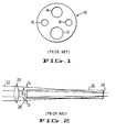
- a common delivery element is an endoscope 10 which is illustrated in cross section in Figure 1.
- the endoscope in Figure 1 is of the type that might be used in a laparoscopy and is often referred to as a laparoscope.
- the laparoscope body will typically have a number of axially extending bores 12, 14, 16 and 18.
- the laser beam may be directed through bore 12.
- Bore 14 may be used for optical feedback so the surgeon can view the tissue site.
- the two smaller bores 16 and 18 can be used to deliver illumination via fiber optic bundles to the treatment site.
- a coupler is used to join the end of the articulated arm to the entrance of the endoscope.
- a number of medical device companies manufacture and sell endoscopes each of which have slightly different entrance end configurations.
- a coupler with a complimentary mating design for each different endoscope design, there exists a coupler with a complimentary mating design.
- the coupler is typically provided with a conically shaped male mating end which is received in a conically shaped female mating configuration formed at the entrance of the endoscope.
- the mating conical configurations allow the two pieces to be adjusted when mounted. The alignment of the system relies heavily on the accuracy of the mating cones.
- the latter mounting approach has been less than satisfactory. More particularly, the prior approach required the doctor to adjust and test the alignment of the beam each time a new endoscope was attached. Since a new sterile endoscope is used for each new surgical procedure, the doctor must repeatedly adjust the alignment of the system. More significantly, even if the doctor is able to initially align the beam, the continuous movement of the articulated arm during the surgical procedure often results in the alignment being lost. If the alignment is lost, the percentage of the beam power transmitted down the endoscope is adversely affected. Moreover, misalignment of the components affects beam shape and size. Accordingly, it would be desirable to provide an improved coupler which could provide accurate and stable alignment of the mating components.
- Figure 2 illustrates the problem.
- the focal power of the lens 20 is selected to bring the focus of the beam 22 near the end 24 of the endoscope 26
- the diameter D1 of the beam at the entrance 28 will be significantly larger than the diameter D2 of the endoscope bore. This disparity results in severe clipping of the beam at the entrance reducing the power injected into the endoscope.
- the subject invention provides for a coupler for use in a medical laser system.
- the laser system is of the type that includes a laser for generating a beam of radiation.
- a delivery system is connected to the laser for delivering the beam to the treatment site.
- the delivery system includes an articulated arm and an endoscope.
- a coupler is provided for connecting the arm to the endoscope.
- the coupler is provided with an axially projecting tube which is receivable in the bore of the endoscope.
- the tube allows the position of the coupler to be registered with respect to the inner surface of the bore.
- the tube extends substantially the length of the bore.
- the tube is shorter and is provided with an adjustment feature to facilitate use with bores of slightly different diameters.
- an elastomeric ring is interposed between the coupler and the end of the endoscope so that registration is independent of the accuracy of the fabrication of the entrance configuration of the endoscope and relies entirely on the interaction between the tube and inner surface of the bore.
- an improved focusing mechanism is provided. More specifically, a two element telescope is provided. The focal powers and positions of the elements are selected so that the diameter of the beam at the entrance of the endoscope is less than the diameter of the bore. In addition, the focal plane of the beam is located just beyond the distal end of the endoscope.
- Figure 1 is a cross sectional view of a conventional endoscope found in the prior art.
- Figure 2 is a schematic illustration of a coupler lens and an endoscope found in the prior art.
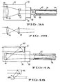
- Figure 3a is a schematic illustration of a coupler formed in accordance with the subject invention shown in conjunction with an endoscope.
- Figure 3b is a schematic illustration of an alternate lens pair for use in the coupler shown in Figure 3a.
- Figure 4a is a schematic illustration of an alternate embodiment of a coupler formed in accordance with the subject invention shown in conjunction with an endoscope.
- Figure 4b is a schematic illustration of an alternate mirror pair for use in the coupler shown in Figure 4a.
- Figure 5 is a cross sectional view of a third embodiment of a coupler formed in accordance with the subject invention shown in conjunction with an endoscope.
- Figure 6 is an exploded perspective view of the adapter flange of the coupler illustrated in Figure 5.
- Figure 7 is a schematic illustration of the mating end of the subject coupler for use with an endoscope having a conical female mating end.
- Figure 8 is a schematic illustration of the mating end of the subject coupler for use with an endoscope having a conical male mating end.
- Figure 9 is a schematic illustration of an alternate embodiment of the coupler of the subject invention shown with an endoscope having a conical female end.
- Figure 10 is a perspective view of the coupler shown in Figure 9.
- Coupler 30 includes a body 32, one end 34 of which is connectable to an articulated arm (not shown).
- the opposed end 36 includes an adapter flange 38.
- Adapter flange 38 is configured to mate with the entrance end 40 of endoscope 42.
- the configuration of the distal end 44 of the flange 38 and the use of coupling nuts (if required) is dictated by the endoscope manufacturer and will be discussed in more detail below with respect to Figures 7 and 8.
- the distal end 44 of flange 38 is additionally provided with an axially projecting tube 46.
- Tube 46 is receivable in the bore 48 of the endoscope 40.
- tube 46 extends substantially the length of the endoscope.
- the outer diameter of the tube is configured to be slightly less than the inner diameter of the endoscope.
- the minimum clearance should be about .001 inches so that the tube 46 can be easily slid into the bore.
- tube 46 results in the alignment of the coupler being registered exactly with the inner surface of the bore of the endoscope. By this arrangement, no adjustment is necessary when the endoscope is mounted to the coupler. In addition, the alignment will be maintained throughout the procedure.
- Figure 3a also illustrates the new focusing system of the subject coupler.
- the focusing system includes a first positive lens 50 for focusing the incoming laser beam.
- a second, negative lens 52 is provided downstream from the positive lens.
- the lens pair functions as a telescope to place the focus of the beam just beyond the distal end 54 of the endoscope. More significantly, the lens pair also adjusts the diameter of the beam at the entrance to the endoscope. In the preferred embodiment, the diameter of the beam at the endoscope entrance is less than the diameter of the bore so that clipping of the beam is avoided even where the diameter of the bore is quite small.
- the position of the lens pair can be fixed within the coupler.
- a means could be provided for adjusting the spacing between the lens pair so that spot size at the end of the endoscope could be varied.
- Figure 3b illustrates an alternative lens pair that is optically equivalent to the pair shown in Figure 3a.
- both of the lenses 56 and 58 are positive elements.
- Figures 4a and 4b illustrate alternate embodiments of the subject coupler 60.
- the focusing elements are defined by curved mirrors.
- both of the mirrors 62 and 64 are positive elements.
- the first mirror 66 is a positive element and the second mirror 68 is a negative element.
- Figure 5 is cross sectional view of a coupler 70 formed in accordance with the subject invention that has been fabricated and tested.
- the main body 72 of the coupler is configured to house and support the positive and negative lenses 74 and 76.
- Each lens is mounted in a lens cell 78 and 80.
- Each lens is mounted by inserting the associated lens cell into the body 72.
- Set screws 82 are used to lock the cells in place and permit some lateral alignment of the lenses.
- Both of the lenses 74 and 76 are formed from zinc selenide which is transmissive to both visible and CO2 radiation.
- the first lens 74 is provided with a focal length of 75mm.
- the second lens is provided with a focal length of -50mm and is spaced from the positive lens a distance of 30mm.
- the negative lens is also spaced from the entrance end of the endoscope 94 by 50mm.
- the endoscope 94 is 350mm long.
- the diameter of the incoming beam from the articulated arm is on the order of 8mm. This diameter is reduced to about 4.8mm in the plane of lens 76.
- the diameter of the beam at the entrance to the endoscope is on the order of 4.28mm which is significantly less than the 5mm of the bore 96.
- the lens system will create a focal plane at the distal end of the endoscope approximately 350mm away from the negative lens 76.
- the diameter of the beam at this location will be approximately 1.5mm.
- Figures 5 and 6 illustrate an alternative form for the flange 102 and alignment tube 104.
- tube 104 extends only a short distance, approximately 50mm, down the length of the 350mm bore of the endoscope. This configuration should be easier to fabricate and assemble. This configuration is also designed to be used with a variety of slightly different size bores.
- the end of the tube 104 is provided with a radially projecting annulus 106.
- the diameter of the annulus 106 can be slightly larger than the inner diameter of the bore 96 of the endoscope.
- the annulus 106 is provided with a plurality of axially extending slots 108. Each slot 108 is about 0.200 inches long and 0.025 inches wide. The slots 108 allow for some compression of the tube into bores-of slightly smaller diameter. This compression fit should enhance stability and help maintain alignment.
- a coupler nut 110 is provided to connect the flange 102 to the body 72.
- Figure 7 and 8 are two alternate configurations for the mating end of the subject coupler designed to interface with the mating ends of existing endoscopes.
- the mating configurations were typically conical.
- the accuracy of these assemblies was dependent on the accuracy of the cones.
- Figure 7 illustrates an endoscope 120 having a female mating cone 122.
- the mating end 124 of the flange of the subject coupler is provided with a spherical surface that centers itself in the female cone 122 independent of the accuracy of the angle of the female cone. Angular alignment of the coupler is then guaranteed by the axially extending tube 126 which projects into and registers with the bore 128 of the endoscope.
- Figure 8 illustrates an endoscope 130 having a male mating cone 132.
- the mating end 134 of the subject coupler is provided with a torroidal surface.
- the torroidal surface centers on the male cone with alignment being provided by the axially extending tube 136.
- the embodiment shown in Figure 9 is designed to overcome the latter problem.
- the flange 140 is not rigidly connected to the entrance 142 of the endoscope 144.
- an elastomeric ring member 146 is inserted between the flange and the entrance 142.
- the ring 146 provides a seat and seal for the coupler while allowing the angle of the coupler to vary with respect to the endoscope bore. In this manner, the alignment of the coupler is not dependent on the accuracy of the construction of the entrance end configuration of the endoscope.
- the alignment of the coupler is based solely on the interface between the alignment tube 148 and the inner surface of the endoscope.
- the alignment tube is provided with a pair of axially spaced annuli 150 and 152. These annuli are similar in function and structure to the annulus 106 illustrated in Figures 5 and 6.
- the second annulus 150 provides the extra kinematic support necessary in this configuration where the flange is floating with respect to the entrance of the endoscope. If annuli are not desired, it would be sufficient to extend the length of the alignment tube down a greater portion of the endoscope bore as shown in Figures 3 and 4.
- Figure 10 is a perspective view of a coupler which has been fabricated and tested.
- the annulus 152 is provided with a plurality of axially extending slots 158 running from the end of the tube 148 a distance of about 0.30 inches.
- a second set of slots 160 extend through the second annulus 150 and along the tube on either side of the annulus.
- the total length of slots 160 is on the order of 0.80 inches.
- the alignment tube 148 is 2.135 inches in length.
- the elastomeric member 146 would be located at the end of the flange as shown in phantom line in Figure 10.
- a suitable elastomeric member would be a rubber ring having a cross sectional diameter of 0.3 to 0.4 inches and formed from silicone rubber.
- a purge gas is typically supplied to the treatment site through a fitting on the side of the endoscope (not shown). Hole 162 is provided in tube 148 to facilitate the flow of the purge gas.
- an elastomeric member as an interface between the flange and the endoscope can be extended to mating configurations other than the one shown in Figure 9.
- the ring could be used where the entrance end of the endoscope has a male conical configuration as shown in Figure 8.
- a ring and flange structure could also be designed for use with the planar mating surface shown in Figure 5.
- the coupler includes an axially extending tube receivable in the bore of an endoscope to improve alignment.
- a telescope optical system is disclosed for reducing the clipping of the beam at the entrance to the endoscope.
Abstract
Description
- A coupler is disclosed particularly suited for use in surgical laser beam delivery systems. The coupler is configured to improve the efficiency of the transmission of the laser beam through the delivery system.
- The use of lasers in various medical procedures is becoming quite common. The type of device used to deliver the laser energy from the laser to the treatment site is primarily dependant upon the wavelength of light generated. For example, 1.06 micron radiation generated by a Nd:YAG laser is typically delivered by an optical fiber formed from a silica compound. In contrast, 10.6 micron radiation generated by a CO₂ laser is typically delivered through an articulated arm assembly since presently existing optical fibers will not efficiently transmit such longer wavelength radiation.
- The present invention is intended for use with an articulated arm. The arm consists of a number of hollow segments connected by rotatable joints. Mirrors are located in each of the joints to redirect the laser beam down the next segment of the arm. One end of the arm is connected to the output of the laser while the other end carries a delivery element.
- The delivery element is selected based on the type of medical procedure which is to be performed. A common delivery element is an
endoscope 10 which is illustrated in cross section in Figure 1. The endoscope in Figure 1 is of the type that might be used in a laparoscopy and is often referred to as a laparoscope. - As seen in Figure 1, the laparoscope body will typically have a number of axially extending
bores bore 12. Bore 14 may be used for optical feedback so the surgeon can view the tissue site. The twosmaller bores - In the prior art, a coupler is used to join the end of the articulated arm to the entrance of the endoscope. In the present commercial environment, a number of medical device companies manufacture and sell endoscopes each of which have slightly different entrance end configurations. For each different endoscope design, there exists a coupler with a complimentary mating design.
- While there exists a wide variety of prior art coupler designs,,all of the existing designs have a few common features. For example, the coupler is typically provided with a conically shaped male mating end which is received in a conically shaped female mating configuration formed at the entrance of the endoscope. The mating conical configurations allow the two pieces to be adjusted when mounted. The alignment of the system relies heavily on the accuracy of the mating cones.
- Unfortunately, the latter mounting approach has been less than satisfactory. More particularly, the prior approach required the doctor to adjust and test the alignment of the beam each time a new endoscope was attached. Since a new sterile endoscope is used for each new surgical procedure, the doctor must repeatedly adjust the alignment of the system. More significantly, even if the doctor is able to initially align the beam, the continuous movement of the articulated arm during the surgical procedure often results in the alignment being lost. If the alignment is lost, the percentage of the beam power transmitted down the endoscope is adversely affected. Moreover, misalignment of the components affects beam shape and size. Accordingly, it would be desirable to provide an improved coupler which could provide accurate and stable alignment of the mating components.
- Another common feature of prior art couplers was the inclusion of a single, positive focusing lens. The lens was used to focus the beam entering the coupler from the articulated arm into the endoscope. The power of the lens was designed to bring the beam to a focus just beyond the distal end of the endoscope.
- The latter design has been used quite successfully with endoscopes wherein the diameter of the bore was quite large. When the bore diameter is large, a high percentage of the beam can be injected down the endoscope. Recently, there has been a trend to develop endoscopes with smaller outer diameters and associated smaller axial bores. As can be appreciated, doctors prefer smaller diameter endoscopes because they are easier to handle and the associated incisions can be made smaller. There has also been a trend to develop endoscopes wherein the diameter of the bore used to transmit the laser beam is reduced while increasing the diameter of the bore of the viewing channel to improve visibility at the treatment site.
- When the diameter of the axial bore for transmitting laser radiation is reduced for either of the above discussed reasons, problems have arisen with the coupling of the laser beam into the endoscope. Figure 2 illustrates the problem. As can be seen, when the focal power of the
lens 20 is selected to bring the focus of thebeam 22 near theend 24 of theendoscope 26, the diameter D₁ of the beam at theentrance 28 will be significantly larger than the diameter D₂ of the endoscope bore. This disparity results in severe clipping of the beam at the entrance reducing the power injected into the endoscope. - A further complication arises as the articulated arm is moved during the procedure. As the arm moves, the level of clipping is varied and the delivered power continuously changes. In addition, the beam is distorted as it reflects off the bore. This distortion causes an irregular shape burn that constantly changes with arm movement. Accordingly, it would be desireable to provide an improved coupler which overcame these problems.
- Accordingly, it is an object of the subject invention to provide a new and improved coupler for use with medical laser delivery systems.
- It is another object of the subject invention to provide a coupler configured to improve the alignment with the endoscope.
- It is a further object of the subject invention to provide a coupler having an axially projecting alignment tube, receivable within the bore of the endoscope for improving alignment.
- It is still another object of the subject invention to provide a coupler having an improved focusing system.
- It is still a further object of the subject invention to provide a coupler with a telescope Focusing system for reducing the clipping of the beam entering the endoscope.
- In accordance with these and many other objects the subject invention provides for a coupler for use in a medical laser system. The laser system is of the type that includes a laser for generating a beam of radiation. A delivery system is connected to the laser for delivering the beam to the treatment site. The delivery system includes an articulated arm and an endoscope. A coupler is provided for connecting the arm to the endoscope.
- In accordance with the subject invention, the coupler is provided with an axially projecting tube which is receivable in the bore of the endoscope. The tube allows the position of the coupler to be registered with respect to the inner surface of the bore. By this arrangement, there is no need to independently adjust the alignment. In addition, the alignment will not drift due to the movement of the articulated arm during the surgical procedure.
- In one embodiment, the tube extends substantially the length of the bore. In another embodiment, the tube is shorter and is provided with an adjustment feature to facilitate use with bores of slightly different diameters. In a further embodiment, an elastomeric ring is interposed between the coupler and the end of the endoscope so that registration is independent of the accuracy of the fabrication of the entrance configuration of the endoscope and relies entirely on the interaction between the tube and inner surface of the bore.
- In another feature of the subject coupler, an improved focusing mechanism is provided. More specifically, a two element telescope is provided. The focal powers and positions of the elements are selected so that the diameter of the beam at the entrance of the endoscope is less than the diameter of the bore. In addition, the focal plane of the beam is located just beyond the distal end of the endoscope. By using this approach, the clipping problems of the prior art are avoided and more beam power will be transmitted down the endoscope.
- Further objects and advantages will become apparent from the following detailed description taken in conjunction with the drawings in which:
- Figure 1 is a cross sectional view of a conventional endoscope found in the prior art.
- Figure 2 is a schematic illustration of a coupler lens and an endoscope found in the prior art.
- Figure 3a is a schematic illustration of a coupler formed in accordance with the subject invention shown in conjunction with an endoscope.
- Figure 3b is a schematic illustration of an alternate lens pair for use in the coupler shown in Figure 3a.
- Figure 4a is a schematic illustration of an alternate embodiment of a coupler formed in accordance with the subject invention shown in conjunction with an endoscope.
- Figure 4b is a schematic illustration of an alternate mirror pair for use in the coupler shown in Figure 4a.
- Figure 5 is a cross sectional view of a third embodiment of a coupler formed in accordance with the subject invention shown in conjunction with an endoscope.
- Figure 6 is an exploded perspective view of the adapter flange of the coupler illustrated in Figure 5.
- Figure 7 is a schematic illustration of the mating end of the subject coupler for use with an endoscope having a conical female mating end.
- Figure 8 is a schematic illustration of the mating end of the subject coupler for use with an endoscope having a conical male mating end.
- Figure 9 is a schematic illustration of an alternate embodiment of the coupler of the subject invention shown with an endoscope having a conical female end.
- Figure 10 is a perspective view of the coupler shown in Figure 9.
- Referring to Figure 3a, there is illustrated a
coupler 30 formed in accordance with the subject invention.Coupler 30 includes abody 32, oneend 34 of which is connectable to an articulated arm (not shown). Theopposed end 36 includes anadapter flange 38.Adapter flange 38 is configured to mate with theentrance end 40 ofendoscope 42. As noted above, there are many manufacturers of endoscopes each using a different mating structure. The configuration of thedistal end 44 of theflange 38 and the use of coupling nuts (if required) is dictated by the endoscope manufacturer and will be discussed in more detail below with respect to Figures 7 and 8. - In accordance with the subject invention, the
distal end 44 offlange 38 is additionally provided with anaxially projecting tube 46.Tube 46 is receivable in thebore 48 of theendoscope 40. In the embodiment illustrated in Figure 3a,tube 46 extends substantially the length of the endoscope. The outer diameter of the tube is configured to be slightly less than the inner diameter of the endoscope. The minimum clearance should be about .001 inches so that thetube 46 can be easily slid into the bore. - As can be appreciated, the use of
tube 46 results in the alignment of the coupler being registered exactly with the inner surface of the bore of the endoscope. By this arrangement, no adjustment is necessary when the endoscope is mounted to the coupler. In addition, the alignment will be maintained throughout the procedure. - Figure 3a also illustrates the new focusing system of the subject coupler. The focusing system includes a first
positive lens 50 for focusing the incoming laser beam. A second,negative lens 52 is provided downstream from the positive lens. The lens pair functions as a telescope to place the focus of the beam just beyond thedistal end 54 of the endoscope. More significantly, the lens pair also adjusts the diameter of the beam at the entrance to the endoscope. In the preferred embodiment, the diameter of the beam at the endoscope entrance is less than the diameter of the bore so that clipping of the beam is avoided even where the diameter of the bore is quite small. - The position of the lens pair can be fixed within the coupler. Alternatively, a means could be provided for adjusting the spacing between the lens pair so that spot size at the end of the endoscope could be varied.
- Figure 3b illustrates an alternative lens pair that is optically equivalent to the pair shown in Figure 3a. In Figure 3b, both of the
lenses - Figures 4a and 4b illustrate alternate embodiments of the
subject coupler 60. In these embodiments, the focusing elements are defined by curved mirrors. In Figure 4a, both of themirrors first mirror 66 is a positive element and thesecond mirror 68 is a negative element. - Figure 5 is cross sectional view of a
coupler 70 formed in accordance with the subject invention that has been fabricated and tested. Themain body 72 of the coupler is configured to house and support the positive andnegative lenses lens cell body 72. Set screws 82 are used to lock the cells in place and permit some lateral alignment of the lenses. - Both of the
lenses first lens 74 is provided with a focal length of 75mm. The second lens is provided with a focal length of -50mm and is spaced from the positive lens a distance of 30mm. The negative lens is also spaced from the entrance end of theendoscope 94 by 50mm. Theendoscope 94 is 350mm long. - The diameter of the incoming beam from the articulated arm is on the order of 8mm. This diameter is reduced to about 4.8mm in the plane of
lens 76. The diameter of the beam at the entrance to the endoscope is on the order of 4.28mm which is significantly less than the 5mm of thebore 96. - It is desirable to allow some margin of error between the diameter of the aligned beam and the inner diameter of the bore since the position of the beam entering the coupler can vary depending on the extent of angular and positional errors (run-out) induced by the movement of the articulated arm. Good design of the articulated arm can minimize run-out errors. Existing arms manufactured by the assignee herein are specified to have a positional run-out limited to 2mm and an angular run-out limited to 3 milliradians. It is anticipated that the beam entering the coupler should not exceed the limits of a 10mm error circle. In this case, the subject lens system should allow nearly all of the beam to be injected into the bore of the endoscope.
- The lens system will create a focal plane at the distal end of the endoscope approximately 350mm away from the
negative lens 76. The diameter of the beam at this location will be approximately 1.5mm. - Figures 5 and 6 illustrate an alternative form for the
flange 102 andalignment tube 104. As can be seen,tube 104 extends only a short distance, approximately 50mm, down the length of the 350mm bore of the endoscope. This configuration should be easier to fabricate and assemble. This configuration is also designed to be used with a variety of slightly different size bores. - To achieve this goal, the end of the
tube 104 is provided with aradially projecting annulus 106. The diameter of theannulus 106 can be slightly larger than the inner diameter of thebore 96 of the endoscope. Theannulus 106 is provided with a plurality of axially extendingslots 108. Eachslot 108 is about 0.200 inches long and 0.025 inches wide. Theslots 108 allow for some compression of the tube into bores-of slightly smaller diameter. This compression fit should enhance stability and help maintain alignment. Acoupler nut 110 is provided to connect theflange 102 to thebody 72. - Figure 7 and 8 are two alternate configurations for the mating end of the subject coupler designed to interface with the mating ends of existing endoscopes. As noted above, in the prior art, the mating configurations were typically conical. the accuracy of these assemblies was dependent on the accuracy of the cones. These problems are overcome with the subject design.
- Figure 7 illustrates an
endoscope 120 having afemale mating cone 122. Themating end 124 of the flange of the subject coupler is provided with a spherical surface that centers itself in thefemale cone 122 independent of the accuracy of the angle of the female cone. Angular alignment of the coupler is then guaranteed by theaxially extending tube 126 which projects into and registers with thebore 128 of the endoscope. - Figure 8 illustrates an
endoscope 130 having amale mating cone 132. Themating end 134 of the subject coupler is provided with a torroidal surface. As in the Figure 7 embodiment, the torroidal surface centers on the male cone with alignment being provided by theaxially extending tube 136. - As noted above there is a significant lack of accuracy in the manufacture of the prior art endoscopes. The approach shown in Figures 7 and 8 is intended to overcome variations in the angle of the conical surface provided at the entrance end of the endoscope. It has also been found that the axis of entrance configuration of an endoscope is often not collinear with the axis of the bore of the endoscope. Accordingly, if the flange of the coupler is rigidly connected and aligned with the axis of the entrance end of the endoscope, the accuracy of the alignment of the beam down the endoscope bore can be comprised.
- The embodiment shown in Figure 9 is designed to overcome the latter problem. In this embodiment, the
flange 140 is not rigidly connected to theentrance 142 of theendoscope 144. In contrast, anelastomeric ring member 146 is inserted between the flange and theentrance 142. Thering 146 provides a seat and seal for the coupler while allowing the angle of the coupler to vary with respect to the endoscope bore. In this manner, the alignment of the coupler is not dependent on the accuracy of the construction of the entrance end configuration of the endoscope. - In this embodiment, the alignment of the coupler is based solely on the interface between the
alignment tube 148 and the inner surface of the endoscope. In the embodiment shown in Figures 9 and 10, the alignment tube is provided with a pair of axially spacedannuli annulus 106 illustrated in Figures 5 and 6. Thesecond annulus 150 provides the extra kinematic support necessary in this configuration where the flange is floating with respect to the entrance of the endoscope. If annuli are not desired, it would be sufficient to extend the length of the alignment tube down a greater portion of the endoscope bore as shown in Figures 3 and 4. - Figure 10 is a perspective view of a coupler which has been fabricated and tested. As in the embodiment of Figures 5 and 6, the
annulus 152 is provided with a plurality of axially extendingslots 158 running from the end of the tube 148 a distance of about 0.30 inches. A second set ofslots 160 extend through thesecond annulus 150 and along the tube on either side of the annulus. The total length ofslots 160 is on the order of 0.80 inches. Thealignment tube 148 is 2.135 inches in length. - The
elastomeric member 146 would be located at the end of the flange as shown in phantom line in Figure 10. A suitable elastomeric member would be a rubber ring having a cross sectional diameter of 0.3 to 0.4 inches and formed from silicone rubber. - A purge gas is typically supplied to the treatment site through a fitting on the side of the endoscope (not shown).
Hole 162 is provided intube 148 to facilitate the flow of the purge gas. - The concept of using an elastomeric member as an interface between the flange and the endoscope can be extended to mating configurations other than the one shown in Figure 9. For example, the ring could be used where the entrance end of the endoscope has a male conical configuration as shown in Figure 8. A ring and flange structure could also be designed for use with the planar mating surface shown in Figure 5.
- In summary, there has been disclosed a new coupler for use with medical lasers. The coupler includes an axially extending tube receivable in the bore of an endoscope to improve alignment. In addition, a telescope optical system is disclosed for reducing the clipping of the beam at the entrance to the endoscope.
- While the subject invention has been described with reference to the preferred embodiments, various changes and modifications could be made therein, by one skilled in the art, without varying from the scope and spirit of the subject invention as defined by the appended claims.
Claims (26)
- A coupler for use with a medical laser system, said system including a laser for generating a laser beam and a delivery means, said delivery means including an arm connected to the output of the laser and an endoscope for insertion into the body of a patient, said endoscope having an axially extending bore through which the laser beam is transmitted, said coupler for joining the arm to the entrance of the endoscope, said coupler comprising:
a body;
a first focusing element located in said body; and
a second focusing element located in said body between said first focusing element and said endoscope, with the focal powers of said focusing elements being selected such that the diameter of the laser beam at the entrance to the endoscope is less than the inner diameter of the bore of the endoscope and with the laser beam being brought to a focus proximate to the opposed end of the endoscope. - A coupler as recited in claim 1 wherein said focusing elements are mirrors.
- A coupler as recited in claim 1 wherein said focusing elements are lenses.
- A coupler for use with a medical laser system, said system including a laser for generating a laser beam and a delivery means, said delivery means including an arm connected to the output of the laser and an endoscope for insertion into the body of a patient, said endoscope having an axially extending bore through which the laser beam is transmitted, said coupler for joining the arm to the entrance of the endoscope, said coupler comprising:
a body, with one end of said body being connected to said arm and with the other end of said body including an adapter flange configured to mate with the entrance of the endoscope, said flange further including an axially projecting alignment tube receivable within the bore of the endoscope and being dimensioned to axially align the coupler with the endoscope. - A coupler as recited in claim 4 wherein said alignment tube includes a radially projecting annulus having an outer diameter substantially corresponding to the inner diameter of the bore of the endoscope.
- A coupler as recited in claim 5 wherein said annulus includes an axial slot providing flexibility and allowing some variation in the outer diameter of the annulus.
- A coupler as recited in claim 4 wherein said alignment tube extends substantially along the entire length of the endoscope.
- A coupler as recited in claim 4 wherein the entrance end of the endoscope has a female conical configuration and wherein the mating surface of the flange is provided with a spherical configuration.
- A coupler as recited in claim 4 wherein the entrance end of the endoscope has a male conical configuration and wherein the mating surface of the flange is provided with a torroidal configuration.
- A coupler as recited in claim 4 further including an elastomeric member located between said flange and bearing upon the entrance to the endoscope to provide a seat for the flange without substantially limiting the alignment of the coupler.
- A coupler as recited in claim 10 wherein said alignment tube includes a pair of axially spaced, radially projecting annuli each having an outer diameter substantially corresponding to the inner diameter of the bore of the endoscope.
- A coupler as recited in claim 11 wherein each said annulus includes an axial slot providing flexibility and allowing some variation in the outer diameter of the annulus.
- A coupler for use with a medical laser system, said system including a laser for generating a laser beam and a delivery means, said delivery means including an arm connected to the output of the laser and an endoscope for insertion into the body of a patient, said endoscope having an axially extending bore through which the laser beam is transmitted, said coupler for joining the arm to the entrance of the endoscope, said coupler comprising:
a body, with one end of said body being connected to said arm and with the other end of said body including an adapter flange, said flange further including an axially projecting alignment tube receivable within the bore of the endoscope through the entrance end thereof; and
an elastomeric ring located between the flange and the entrance to the endoscope to provide a seat for the flange without substantially limiting the alignment of the coupler. - A coupler as recited in claim 13 wherein said alignment tube includes a pair of axially spaced, radially projecting annuli each having an outer diameter substantially corresponding to the inner diameter of the bore of the endoscope.
- A coupler as recited in claim 14 wherein each said annulus includes an axial slot providing flexibility and allowing some variation in the outer diameter of the annulus.
- A coupler for use with a medical laser system, said system including a laser for generating a laser beam and a delivery means, said delivery means including an arm connected to the output of the laser and an endoscope for insertion into the body of a patient, said endoscope having an axially extending bore through which the laser beam is transmitted, said coupler for joining the arm to the entrance of the endoscope, said coupler comprising:
a body, with one end of said body being connected to said arm and with the other end of said body including an adapter flange configured to mate with the entrance of the endoscope, said flange further including an axially projecting alignment tube receivable within the bore of the endoscope and being dimensioned to axially align the coupler with the endoscope;
a first focusing element located in said body; and
a second focusing element located in said body between said positive focusing element and said endoscope, with the focal powers of said focusing elements being selected such that the diameter of the laser beam at the entrance to the endoscope is less than the inner diameter of the bore of the endoscope and with the laser beam being brought to a focus proximate to the opposed end of the endoscope. - A coupler as recited in claim 16 wherein said focusing elements are mirrors.
- A coupler as recited in claim 16 wherein said focusing elements are lenses.
- A coupler as recited in claim 16 wherein said alignment tube includes a radially projecting annulus having an outer diameter substantially corresponding to the inner diameter of the bore of the endoscope.
- A coupler as recited in claim 19 wherein said annulus includes an axial slot providing flexibility and allowing some variation in the outer diameter of the annulus.
- A coupler as recited in claim 16 wherein said alignment tube extends substantially along the entire length of the endoscope.
- A coupler as recited in claim 16 wherein the entrance end of the endoscope has a female conical configuration and wherein the mating surface of the flange is provided with a spherical configuration.
- A coupler as recited in claim 16 wherein the entrance end of the endoscope has a male conical configuration and wherein the mating surface of the flange is provided with a torroidal configuration.
- A coupler as recited in claim 16 further including an elastomeric member located between said flange and bearing upon the entrance to the endoscope to provide a seat for the flange without substantially limiting the alignment of the coupler.
- A coupler as recited in claim 24 wherein said alignment tube includes a pair of axially spaced, radially projecting annuli each having an outer diameter substantially corresponding to the inner diameter of the bore of the endoscope.
- A coupler as recited in claim 25 wherein each said annulus includes an axial slot providing flexibility and allowing some variation in the outer diameter of the annulus.
Applications Claiming Priority (4)
| Application Number | Priority Date | Filing Date | Title |
|---|---|---|---|
| US69424591A | 1991-05-01 | 1991-05-01 | |
| US694245 | 1991-05-01 | ||
| US07/737,395 US5136676A (en) | 1991-05-01 | 1991-07-29 | Coupler for a laser delivery system |
| US737395 | 1991-07-29 |
Publications (3)
| Publication Number | Publication Date |
|---|---|
| EP0511805A2 true EP0511805A2 (en) | 1992-11-04 |
| EP0511805A3 EP0511805A3 (en) | 1993-06-23 |
| EP0511805B1 EP0511805B1 (en) | 1997-07-02 |
Family
ID=27105336
Family Applications (1)
| Application Number | Title | Priority Date | Filing Date |
|---|---|---|---|
| EP92303767A Expired - Lifetime EP0511805B1 (en) | 1991-05-01 | 1992-04-27 | Coupler for a laser delivery system |
Country Status (4)
| Country | Link |
|---|---|
| EP (1) | EP0511805B1 (en) |
| JP (1) | JPH05181085A (en) |
| DE (1) | DE69220614T2 (en) |
| IL (1) | IL101471A (en) |
Cited By (7)
| Publication number | Priority date | Publication date | Assignee | Title |
|---|---|---|---|---|
| WO1995019147A1 (en) * | 1994-01-14 | 1995-07-20 | Coherent, Inc. | Handpiece for producing highly collimated laser beam for dermatological procedures |
| FR2737786A1 (en) * | 1995-08-11 | 1997-02-14 | Soc D Production Et De Rech Ap | OPTICAL DEVICE FOR HOMOGENEIZING A LASER BEAM |
| FR2737814A1 (en) * | 1995-08-11 | 1997-02-14 | Soc D Production Et De Rech Ap | METHOD AND DEVICE FOR CONTROLLING A LASER SOURCE WITH MULTIPLE LASER MODULES TO OPTIMIZE LASER SURFACE TREATMENT |
| WO2002076290A1 (en) * | 2001-03-21 | 2002-10-03 | Visionscope, Inc. | Miniature endoscope system |
| EP1417520A2 (en) * | 2001-02-09 | 2004-05-12 | Sanmina-SCI Corporation | Fiber-optic cable alignment system |
| US6963678B2 (en) | 2001-02-09 | 2005-11-08 | Sanmina-Sci Corporation | Electro-optical transducer with multi-reflector beam-expanding and collimating input/output device |
| WO2010118197A1 (en) * | 2009-04-10 | 2010-10-14 | Raytheon Company | Laser to optical fiber coupling device and method |
Families Citing this family (1)
| Publication number | Priority date | Publication date | Assignee | Title |
|---|---|---|---|---|
| US8317689B1 (en) | 1999-09-13 | 2012-11-27 | Visionscope Technologies Llc | Miniature endoscope system |
Citations (9)
| Publication number | Priority date | Publication date | Assignee | Title |
|---|---|---|---|---|
| DE2059821A1 (en) * | 1970-12-04 | 1972-06-22 | Kutter Anton Dipl Ing | Mirror telescope in a Schiefspiegler arrangement |
| US3982541A (en) * | 1974-07-29 | 1976-09-28 | Esperance Jr Francis A L | Eye surgical instrument |
| DE2810879A1 (en) * | 1977-03-14 | 1978-10-05 | Spectra Med | DEVICE AND METHOD FOR CAUTERIZING BLOOD VESSELS AND OTHER BIOLOGICAL TISSUE |
| US4144888A (en) * | 1976-09-15 | 1979-03-20 | Malyshev Boris N | Device for treatment by laser emission |
| DE2803898A1 (en) * | 1978-01-30 | 1979-08-02 | Sigma Instr Gmbh | Laser endoscope for internal surgery - has laser beam passage with reflecting component in front of observation end of eyepiece |
| EP0196519A2 (en) * | 1985-04-01 | 1986-10-08 | Children's Hospital Medical Center | Method and apparatus for transmyocardial revascularization using a laser |
| WO1989006518A1 (en) * | 1988-01-12 | 1989-07-27 | Ulrich-Dardenne-Stiftung E.V. | Device for ablative photodecomposition of organic and inorganic substances, in particular hard dental materials |
| EP0351240A2 (en) * | 1988-07-14 | 1990-01-17 | Advanced Interventional Systems, Inc. | Guidance and delivery system for high-energy pulsed laser light |
| US5000553A (en) * | 1989-02-09 | 1991-03-19 | El. En S.R.L. | Apparatus for the alignment of a laser beam inside an articulated tubular arm |
-
1992
- 1992-04-02 IL IL10147192A patent/IL101471A/en not_active IP Right Cessation
- 1992-04-27 EP EP92303767A patent/EP0511805B1/en not_active Expired - Lifetime
- 1992-04-27 DE DE69220614T patent/DE69220614T2/en not_active Expired - Fee Related
- 1992-04-30 JP JP4137952A patent/JPH05181085A/en active Pending
Patent Citations (9)
| Publication number | Priority date | Publication date | Assignee | Title |
|---|---|---|---|---|
| DE2059821A1 (en) * | 1970-12-04 | 1972-06-22 | Kutter Anton Dipl Ing | Mirror telescope in a Schiefspiegler arrangement |
| US3982541A (en) * | 1974-07-29 | 1976-09-28 | Esperance Jr Francis A L | Eye surgical instrument |
| US4144888A (en) * | 1976-09-15 | 1979-03-20 | Malyshev Boris N | Device for treatment by laser emission |
| DE2810879A1 (en) * | 1977-03-14 | 1978-10-05 | Spectra Med | DEVICE AND METHOD FOR CAUTERIZING BLOOD VESSELS AND OTHER BIOLOGICAL TISSUE |
| DE2803898A1 (en) * | 1978-01-30 | 1979-08-02 | Sigma Instr Gmbh | Laser endoscope for internal surgery - has laser beam passage with reflecting component in front of observation end of eyepiece |
| EP0196519A2 (en) * | 1985-04-01 | 1986-10-08 | Children's Hospital Medical Center | Method and apparatus for transmyocardial revascularization using a laser |
| WO1989006518A1 (en) * | 1988-01-12 | 1989-07-27 | Ulrich-Dardenne-Stiftung E.V. | Device for ablative photodecomposition of organic and inorganic substances, in particular hard dental materials |
| EP0351240A2 (en) * | 1988-07-14 | 1990-01-17 | Advanced Interventional Systems, Inc. | Guidance and delivery system for high-energy pulsed laser light |
| US5000553A (en) * | 1989-02-09 | 1991-03-19 | El. En S.R.L. | Apparatus for the alignment of a laser beam inside an articulated tubular arm |
Cited By (11)
| Publication number | Priority date | Publication date | Assignee | Title |
|---|---|---|---|---|
| WO1995019147A1 (en) * | 1994-01-14 | 1995-07-20 | Coherent, Inc. | Handpiece for producing highly collimated laser beam for dermatological procedures |
| US5558666A (en) * | 1994-01-14 | 1996-09-24 | Coherent, Inc. | Handpiece for producing highly collimated laser beam for dermatological procedures |
| FR2737786A1 (en) * | 1995-08-11 | 1997-02-14 | Soc D Production Et De Rech Ap | OPTICAL DEVICE FOR HOMOGENEIZING A LASER BEAM |
| FR2737814A1 (en) * | 1995-08-11 | 1997-02-14 | Soc D Production Et De Rech Ap | METHOD AND DEVICE FOR CONTROLLING A LASER SOURCE WITH MULTIPLE LASER MODULES TO OPTIMIZE LASER SURFACE TREATMENT |
| WO1997007578A1 (en) * | 1995-08-11 | 1997-02-27 | Societe De Production Et De Recherches Appliquees | Device for controlling a laser source with multiple laser units for the energy and spatial optimisation of a laser surface treatment |
| US6014401A (en) * | 1995-08-11 | 2000-01-11 | Societe De Production Et De Recherches Appliquees | Device for controlling a laser source with multiple laser units for the energy and spatial optimization of a laser surface treatment |
| EP1417520A2 (en) * | 2001-02-09 | 2004-05-12 | Sanmina-SCI Corporation | Fiber-optic cable alignment system |
| EP1417520A4 (en) * | 2001-02-09 | 2005-03-23 | Sanmina Sci Corp | Fiber-optic cable alignment system |
| US6963678B2 (en) | 2001-02-09 | 2005-11-08 | Sanmina-Sci Corporation | Electro-optical transducer with multi-reflector beam-expanding and collimating input/output device |
| WO2002076290A1 (en) * | 2001-03-21 | 2002-10-03 | Visionscope, Inc. | Miniature endoscope system |
| WO2010118197A1 (en) * | 2009-04-10 | 2010-10-14 | Raytheon Company | Laser to optical fiber coupling device and method |
Also Published As
| Publication number | Publication date |
|---|---|
| IL101471A (en) | 1995-03-30 |
| EP0511805A3 (en) | 1993-06-23 |
| IL101471A0 (en) | 1992-12-30 |
| EP0511805B1 (en) | 1997-07-02 |
| DE69220614T2 (en) | 1998-01-08 |
| JPH05181085A (en) | 1993-07-23 |
| DE69220614D1 (en) | 1997-08-07 |
Similar Documents
| Publication | Publication Date | Title |
|---|---|---|
| US5136676A (en) | Coupler for a laser delivery system | |
| US5163936A (en) | Endoscopic mirror laser beam delivery system and method for controlling alignment | |
| EP1315443B1 (en) | Variable view arthroscope | |
| US5430620A (en) | Compact surgical illumination system capable of dynamically adjusting the resulting field of illumination | |
| US6513962B1 (en) | Illumination system adapted for surgical lighting | |
| JP5809163B2 (en) | Multi-spot laser probe | |
| US5289557A (en) | Optics for medical laser | |
| US4402569A (en) | Optical fibre light guides for use with lasers | |
| EP0336045A1 (en) | Delivery arrangement for a laser medical system | |
| JP2023009158A (en) | Multi-fiber multi-spot laser probe with simplified tip construction | |
| WO2005040863A2 (en) | Apparatus and method for diffusing laser energy that fails to couple into small core fibers | |
| US9782063B2 (en) | Optical coupling efficiency detection assembly and method of assembling the same | |
| EP0511805A2 (en) | Coupler for a laser delivery system | |
| US5852694A (en) | High power fiber optic connector | |
| US6512868B1 (en) | Precision fiber optic collimator | |
| US5243399A (en) | Alignment tool for endoscopes | |
| US11809011B2 (en) | Alignment method and tools | |
| US5251612A (en) | Self-aligning coupler for a laser endoscope | |
| US4856512A (en) | Laser head and microscope attachment assembly with swivel capability | |
| EP0392718B1 (en) | Optical connector for endoscope | |
| JP2000002822A (en) | Optical connector and laser beam generator | |
| JPS63311314A (en) | Optical coupler | |
| JP2021511843A (en) | Optical path switching structure used for the handle of the oral laser treatment device | |
| IL100441A (en) | Coupler device for laser apparatus | |
| JPH0468944B2 (en) |
Legal Events
| Date | Code | Title | Description |
|---|---|---|---|
| PUAI | Public reference made under article 153(3) epc to a published international application that has entered the european phase |
Free format text: ORIGINAL CODE: 0009012 |
|
| AK | Designated contracting states |
Kind code of ref document: A2 Designated state(s): CH DE FR GB IT LI |
|
| PUAL | Search report despatched |
Free format text: ORIGINAL CODE: 0009013 |
|
| AK | Designated contracting states |
Kind code of ref document: A3 Designated state(s): CH DE FR GB IT LI |
|
| 17P | Request for examination filed |
Effective date: 19931216 |
|
| 17Q | First examination report despatched |
Effective date: 19950512 |
|
| GRAG | Despatch of communication of intention to grant |
Free format text: ORIGINAL CODE: EPIDOS AGRA |
|
| GRAH | Despatch of communication of intention to grant a patent |
Free format text: ORIGINAL CODE: EPIDOS IGRA |
|
| GRAH | Despatch of communication of intention to grant a patent |
Free format text: ORIGINAL CODE: EPIDOS IGRA |
|
| RAP1 | Party data changed (applicant data changed or rights of an application transferred) |
Owner name: COHERENT, INC. |
|
| RIN1 | Information on inventor provided before grant (corrected) |
Inventor name: KOOP, DALE Inventor name: TROST, DAVID Inventor name: ARNETT, MICHAEL |
|
| GRAA | (expected) grant |
Free format text: ORIGINAL CODE: 0009210 |
|
| AK | Designated contracting states |
Kind code of ref document: B1 Designated state(s): CH DE FR GB IT LI |
|
| PG25 | Lapsed in a contracting state [announced via postgrant information from national office to epo] |
Ref country code: IT Free format text: LAPSE BECAUSE OF FAILURE TO SUBMIT A TRANSLATION OF THE DESCRIPTION OR TO PAY THE FEE WITHIN THE PRESCRIBED TIME-LIMIT;WARNING: LAPSES OF ITALIAN PATENTS WITH EFFECTIVE DATE BEFORE 2007 MAY HAVE OCCURRED AT ANY TIME BEFORE 2007. THE CORRECT EFFECTIVE DATE MAY BE DIFFERENT FROM THE ONE RECORDED. Effective date: 19970702 Ref country code: FR Free format text: THE PATENT HAS BEEN ANNULLED BY A DECISION OF A NATIONAL AUTHORITY Effective date: 19970702 |
|
| REG | Reference to a national code |
Ref country code: CH Ref legal event code: EP |
|
| REF | Corresponds to: |
Ref document number: 69220614 Country of ref document: DE Date of ref document: 19970807 |
|
| ET | Fr: translation filed | ||
| REG | Reference to a national code |
Ref country code: CH Ref legal event code: NV Representative=s name: BOVARD AG PATENTANWAELTE |
|
| PG25 | Lapsed in a contracting state [announced via postgrant information from national office to epo] |
Ref country code: GB Free format text: LAPSE BECAUSE OF NON-PAYMENT OF DUE FEES Effective date: 19980427 |
|
| PG25 | Lapsed in a contracting state [announced via postgrant information from national office to epo] |
Ref country code: CH Free format text: LAPSE BECAUSE OF NON-PAYMENT OF DUE FEES Effective date: 19980430 Ref country code: LI Free format text: LAPSE BECAUSE OF NON-PAYMENT OF DUE FEES Effective date: 19980430 |
|
| PLBE | No opposition filed within time limit |
Free format text: ORIGINAL CODE: 0009261 |
|
| STAA | Information on the status of an ep patent application or granted ep patent |
Free format text: STATUS: NO OPPOSITION FILED WITHIN TIME LIMIT |
|
| 26N | No opposition filed | ||
| REG | Reference to a national code |
Ref country code: CH Ref legal event code: PL |
|
| GBPC | Gb: european patent ceased through non-payment of renewal fee |
Effective date: 19980427 |
|
| PG25 | Lapsed in a contracting state [announced via postgrant information from national office to epo] |
Ref country code: DE Free format text: LAPSE BECAUSE OF NON-PAYMENT OF DUE FEES Effective date: 19990202 |
|
| REG | Reference to a national code |
Ref country code: FR Ref legal event code: ST |