EP0511684A2 - Phase modulated fibre-optic gyroscope - Google Patents
Phase modulated fibre-optic gyroscope Download PDFInfo
- Publication number
- EP0511684A2 EP0511684A2 EP92108242A EP92108242A EP0511684A2 EP 0511684 A2 EP0511684 A2 EP 0511684A2 EP 92108242 A EP92108242 A EP 92108242A EP 92108242 A EP92108242 A EP 92108242A EP 0511684 A2 EP0511684 A2 EP 0511684A2
- Authority
- EP
- European Patent Office
- Prior art keywords
- light
- component
- gyroscope
- phase modulation
- fibre
- Prior art date
- Legal status (The legal status is an assumption and is not a legal conclusion. Google has not performed a legal analysis and makes no representation as to the accuracy of the status listed.)
- Granted
Links
Images
Classifications
-
- G—PHYSICS
- G01—MEASURING; TESTING
- G01C—MEASURING DISTANCES, LEVELS OR BEARINGS; SURVEYING; NAVIGATION; GYROSCOPIC INSTRUMENTS; PHOTOGRAMMETRY OR VIDEOGRAMMETRY
- G01C19/00—Gyroscopes; Turn-sensitive devices using vibrating masses; Turn-sensitive devices without moving masses; Measuring angular rate using gyroscopic effects
- G01C19/58—Turn-sensitive devices without moving masses
- G01C19/64—Gyrometers using the Sagnac effect, i.e. rotation-induced shifts between counter-rotating electromagnetic beams
- G01C19/72—Gyrometers using the Sagnac effect, i.e. rotation-induced shifts between counter-rotating electromagnetic beams with counter-rotating light beams in a passive ring, e.g. fibre laser gyrometers
Definitions
- This invention relates to a phase modulated fiber-optic gyroscope according to the preamble of claim 1,
- the fiber-optic gyroscope is an apparatus for measuring the angular velocity of a moving object.
- Monochromatic light is launched at opposite ends of a coil of many turns of a single-mode optical fiber and is transmitted clockwise and counterclockwise simultaneously, with the light emerging from one end of the coil interfering with the light emerging from the other end. If the fiber-optic coil is rotating about its own axis, a phase difference appears between the two light beams. Since this phase difference is proportional to the angular velocity of the rotation, one can determine the angular velocity of the rotation from the phase difference.
- phase difference and angular velocity are written as ⁇ e and Q, respectively, the following relationship holds: where L is the fiber length of the sensor coil, a is the coil diameter, c is the speed of the light in a vacuum and is the wavelength of the light in a vacuum. This effect is called the Sagnac effect and is well known.
- phase difference ⁇ e In practice, however, it is not easy to detect the phase difference ⁇ e because it contains non-rotational offsets inherent in the optical system. These offsets are subject to significant variations due to temperature changes.
- a further problem is that the output of a light-receiving device appears in the form of (1 + cos ⁇ ) in a fiber-optic gyroscope of the most primitive design. This results in low sensitivity and failure to detect the direction of rotation if ⁇ e is small.
- the present invention relates to a fiber-optic gyroscope that operates on the principle of phase modulation.
- phase modulation is produced from a piezoelectric device around which one end portion of the optical fiber cable in the sensor coil is wound. By picking up the first-order term of the modulated wave, the phase difference can be determined in the form of sin ⁇ .
- Coherent light issuing from a light-emitting device 1 is split into two beams by a beam splitter 2.
- One of the two beams is converged by a coupling lens 4 and launched into end A of an optical fiber cable 5. This beam is transmitted through the sensor coil 6 counterclockwise.
- the other beam is converged by a coupling lens 3, launched into end B of the optical fiber 5 and transmitted through the sensor coil 6 clockwise.
- the greater part of the optical fiber cable 5 forms the sensor coil 6 and only the part close to end B is wound around the piezoelectric device to form a phase modulation device 7.
- An oscillator 10 produces an oscillating voltage that causes the piezoelectric device to expand or contract.
- the phase modulating part 8 of the optical fiber cable is wound onto the piezoelectric device, so it will expand or contract together with the piezoelectric device to produce a light signal containing a modulated component.
- the light beam transmitted clockwise through the phase modulating part 8 and the sensor coil 6 will emerge from end A, and the other beam transmitted counterclockwise through the sensor coil 6 and the phase modulating part 8 will emerge at end B.
- the emerging light beams are recombined by the beam splitter 2 and launched as a single beam into a light-receiving device 9, which performs square-law detection on the light of interference.
- the phase modulation device 7 Since the phase modulation device 7 is located asymmetrically with respect to the fiber-optic cable 5, the light being transmitted clockwise is phase-modulated at a slightly different time than the light being transmitted counterclockwise.
- the time, T required for the light to pass through the sensor coil 6 is given by: where L is the fiber length of the sensor coil 6 and n is the refractive index of the fiber core. If the phase modulation device 7 is positioned close to end B, the light being transmitted clockwise will be first phase-modulated before it is launched into the sensor coil 6. On the other hand, the light being transmitted counterclockwise passes through the sensor coil 6 before it is launched into the phase modulation device 7.
- the Sagnac effect introduces a phase difference of ⁇ between the light transmitted clockwise and the light transmitted counterclockwise, and the phase modulation applied on the two light beams creates an additional phase difference of ⁇ in the phase-modulated portion.
- the two light beams having these field strengths are subjected to square-law detection in the light-receiving device 9.
- the output of the light-receiving device, S( ⁇ , t), is given by: where D.C. denotes the dc component, and ⁇ is the number of vibrations of light waves, with 2 ⁇ representing a component having twice the number of vibration w.
- D.C. denotes the dc component
- ⁇ is the number of vibrations of light waves, with 2 ⁇ representing a component having twice the number of vibration w.
- Such a fast signal cannot be detected by the light-receiving device 9 and hence is zero.
- the output signal from the light-receiving device 9 contains the phase-modulated component ⁇ , so the phase difference ⁇ can be determined in association with the amplitude of the modulation signal.
- the second harmonic component Q is: Since the modulation index ⁇ must be held constant, the phase modulation device is controlled in such a way that Q is constant. In other words, ⁇ is controlled to become 1.8. When ⁇ is 1.8, J 2 is about 0.3. If ⁇ becomes greater than 1.8, J 2 increases and vice versa. Hence, ⁇ can be adjusted to 1.8 by holding Q constant.
- JP-A-60-135816 (the term "JP-A” as used herein means an "unexamined published Japanese patent application”) proposes a control system that provides a constant dc component in output signal. But the problem associated with the quantity of reflected light is not discussed in this patent.
- reflected light is meant those components of light which are reflected from the edge faces of lenses, fiber and other parts of the optical system. These components will not contribute to the measurement of angular velocity but simply become noise. In contrast, signal light passes through the sensor coil and contributes to the measurement of angular velocity.
- the light-receiving device receives both signal light and reflected light.
- the reflected light does not pass through the sensor coil.
- the control system described in JP-A-60-135816 assumes either the absence of reflected light or the presence of reflected light that will vary in the same way as does the signal light. Only in that case is valid the statement that holding the dc component constant is equivalent to controlling the amplitude of the light to be constant. In practice, however, a quantity of reflected light that is by no means negligible is launched into the light-receiving device. Reflected light will not fluctuate in the same way as does the signal light, or one may say that it will hardly fluctuate. The phase modulation index will also sometimes fluctuate. Therefore, holding the dc component constant does not necessarily result in a constant amplitude of the signal light.
- the prior art fiber-optic gyroscope suffers the problem that substantial variations occur in the quantity of light that is issued from the light-emitting device to be launched into the optical fiber cable.
- substantial variations can occur in the amplitude E o .Thus, apparently different outputs will be produced for the same angular velocity on account of these variations in the quantity of light.
- JP-A-61-147106 proposes a control system that is capable of maintaining a constant level of the dc component in the signal.
- JP-A-60-135816 already cited above proposes that the effects of variations in the quantity of light be cancelled by dividing the phase-modulated frequency component of the signal by the dc component.
- a phase-modulated fiber-optic gyroscope that operates with the second harmonic component controlled to be constant has also been proposed (see the already cited Japanese Patent Application No. 59-244641).
- the second harmonic component contains J 2 ( ⁇ ) and holding it constant was considered to be equivalent to controlling the phase modulation index to become constant. However, holding the dc component constant is by no means equivalent to controlling the quantity of light to be constant.
- the dc component contains ⁇ e in the form of cos ⁇ .
- the invention described in Japanese Patent Application No. 59-244641 adopts the approximation of ⁇ 0 and controls the dc component to become constant on the assumption that it is proportional to the intensity of the light issuing from the light-emitting device.
- ⁇ e sometimes have such a great magnitude that it cannot be neglected. If ⁇ e is substantial, the approximation of ⁇ 0 will produce inaccuracy.
- the second harmonic component Q has not only the J2( ⁇ ) term but also the cos ⁇ term.
- the second harmonic component is held constant on the basis of the approximation that ⁇ e is nearly equal to zero. However, this approximation is by no means exact if ⁇ is great. This will eventually result in failure to maintain a constant value of the phase modulation index.
- the dc component D of the light of interference which is the output of the light-receiving device can be written as: where H is the quantity of reflected light. If the modulated frequency component in equation (16) is eliminated and if E0 2 is rewritten as E 1 E 2 , the fundamental component P is given by: In order to obtain correct results by dividing the fundamental component by the dc component, the following assumptions must be taken into account in addition to the problem of reflected light:
- the gyroscope according to the preamble of claim 1 is known from the EP-A-0 185 385.
- the phase modulation type fibre-optic gyroscope known from this reference has an improved output stability without a large increase in the number of basic components of the gyroscope system.
- the DC component of the output of a light detecting element which provides the two circulating beams is sensed and employed to control the output of the light emitting element so as to be constant.
- the fiber-optic gyroscope of the present invention may operate on the following principles:
- a light-emitting device 101 is a light source of coherent light and may be composed of any apparatus such as a semiconductor laser, a super-luminescent diode or gas laser.
- a beam splitter 102 divides the coherent light from the light-emitting device 101 into two light beams.
- the term "beam splitter” is used herein to mean a light dividing device in its broad sense.
- the two split light beams are converged by lenses 103 and 104 and launched into an optical fiber cable 105 at opposite ends A and B.
- the optical fiber cable 105 is made of a single-mode optical fiber and includes a sensor coil 106 consisting of many turns of the optical fiber and a portion 108 wound around a phase modulation device 107. The sensor coil detects the angular velocity of rotation.
- the phase modulation device 107 comprises a piezoelectric device, typically in cylindrical form, that is provided with electrodes on an outside and an inside surface and around which the optical fiber cable is wound.
- the phase modulation device 107 imparts periodic phase changes to the light being transmitted through the fiber-optic cable.
- a modulation voltage of a frequency Q from a phase modulation device excitation control unit 115.
- the amplitude of the applied voltage is proportional to the phase modulation index.
- the light beam launched at end A is transmitted clockwise through the sensor coil 106, whereas the light beam launched at end B is transmitted counterclockwise.
- the two light beams emerging from the fiber-optic cable are re-combined by the beam splitter 102 and are launched as a single beam into a light-receiving device 109.
- the light-receiving device 109 detects the intensity of the light of interference and produces it as an output.
- the output from the light-receiving device contains the dc component D, the fundamental component P, the second harmonic component Q and harmonics of higher orders.
- the dc component D is detected by a dc component detector 110.
- the detected signal is sent to a dc component control unit 112.
- the dc component is used to stabilize the output of the light-emitting device but it does not always control the latter. It is used to control the output of the light-emitting device only if a stop signal U is applied from another sensor or when the final output S of the gyroscope per se is zero.
- the dc component control unit 112 supplies a light-emitting device control circuit 113 with a drive current W for the light-emitting device.
- the control unit 112 controls the dc component D of the output from the light-receiving device in such a way that said dc component is held constant when a stop signal U is supplied or when the final output S is zero.
- the stop signal U need not refer to a "stop” in the strict sense of the term and a state close to "stop” may also be indicated. The same is true with the final output S and it need only be close to zero.
- the dc component control unit 112 stores the dc component D when the gyroscope is either stopped or in a state close to stop; it then compares the stored dc component with a predetermined value Do and supplies a command to the light-emitting device output control circuit 113 so that the stored dc component will approach the predetermined value Do.
- the fundamental component P of the output from the light-receiving device 109 is detected by the fundamental detector 117.
- a sync signal is supplied from the phase modulation device excitation control unit 115.
- the second harmonic component Q of the output from the light-receiving device 109 is detected by a second harmonic detector 111.
- the modulation signal from the control unit 115 is doubled in a multiplier 120 to produce a sync signal.
- the modulation index of the control unit 115 is controlled in such a way as to provide a constant level of the second harmonic component.
- the modulation index is theoretically expressed by b but since it is proportional to £, may also be designated the modulation index.
- the second harmonic component is not always controlled to be constant. Only when a stop signal U is supplied from another sensor or if the final output S from the gyroscope is either equal or close to zero is the second harmonic component controlled to become equal to a predetermined value Q o .
- Such an intermittent control is performed by a second harmonic control unit 114.
- the gyroscope which is at rest or in a state very close to it is identified by the supply of either a stop signal from another sensor or a substantially zero output S from the gyroscope.
- the value of the second harmonic component Q in that instance is adopted by the control unit 114 which compares it with Q o and supplies the modulation index ⁇ of the phase modulation device excitation control unit 115 in such a way that the difference between Q and Qo will be minimized.
- the fundamental component P appears as the output of the fundamental detector 117, which serves as the final output S.
- This is equivalent to equation (16) except that the vibration term is eliminated:
- the intensity of the light E 0 2 can be held constant.
- the phase modulation index ⁇ can be held constant.
- the coefficients in equation (118) are held constant, and ⁇ e can be determined from the final output S in the form of sin ⁇ .
- the second harmonic component is detected and controlled to be constant in order to maintain a constant level of the phase modulation index. It should, however, be noted that in place of the second harmonic component, the third or fourth harmonic component may be controlled to be constant in order to maintain a constant level of the phase modulation index. This is possible since all the harmonics of interest contain the phase modulation index.
- the dc component D of the output from the light-receiving device can be rewritten as:
- the modulation index ⁇ may assume any value but here a special case is considered.
- the first-order Bessel function J 1 ( ⁇ ) need be maximized, with ⁇ selected at a value of approximately 1.8.
- the zero-order Bessel function J o ( ⁇ ) is approximately 0.3.
- the dc component D is therefore written as: When the fiber-optic gyroscope is either at rest or nearly at rest, Hence, when the gyroscope is either at rest or nearly at rest, and by controlling D to become equal to the predetermined D o ,the quantity of the light of interference, E 1 E 2 , can be held constant. This is accomplished by the dc component detector 110, the dc component control unit 112, the light-emitting device output control circuit 113, and other associated components shown in Fig. 4.
- Equation (126) E, E 2 which is the quantity of light issuing from the light-emitting device is already constant.
- E, E 2 which is the quantity of light issuing from the light-emitting device is already constant.
- cos ⁇ e is unity.
- the excitation voltage to be applied to the phase modulation device excitation control unit 15 is so controlled as to bring Q to a constant value.
- the phase modulation index ⁇ can be controlled to be constant
- the final output S or the fundamental component P is expressed as follows from equation (118):
- the coefficients preceding sin ⁇ are invariable constants and the exact value of ⁇ e can be determined from the output S. This effect can never be attained simply by controlling the quantity of light or the modulation index alone.
- Fig. 3 shows another embodiment of the present invention which employs the construction shown in Fig. 2.
- the components which are the same as those shown in Fig. 2 are identified by like numerals and will not be described in detail.
- the dc component detector 110 is supplied with the output from the light-receiving 109 and produces the dc component of said output as a voltage signal, which is converted to a digital signal in an A/D converter 122.
- a control signal for controlling the quantity of the light issuing from the light-emitting device in such a way that the dc component D becomes equal to the preset value Do is calculated and constructed.
- This control signal is converted to an analog signal in a D/A converter 121 and supplied to the light-emitting device output control circuit 113.
- the control signal constructed for the previous case where the gyroscope was at rest is retained and delivered as an output. Since it is handled as a digital signal by a digital processing unit 116, the control signal can be easily retained and continuously supplied as an output.
- the light-emitting device output control circuit 113 controls the quantity of the light emerging from the light-emitting device.
- An oscillator 118 generates a modulation signal having a frequency Q.
- the output of the oscillator 118 is fed to a multiplier 119 where it is amplified by an appropriate factor.
- the amplified phase modulation signal is applied to the electrodes of the phase modulation device 107.
- ⁇ or the modulation index b which is to be provided by the phase modulation device 107 can be freely adjusted by controlling the factor of amplification with the multiplier 119.
- the fundamental component P is fed to an A/D converter 124 and thence supplied into the digital processing unit 116.
- Multiplier 120 multiplies the phase modulation signal from the oscillator 118 to form a sync signal having a frequency of 2Q.
- the second harmonic detector 111 detects the second harmonic component Q of the output from the light-receiving device. The detected signal is fed to an A/D converter 125 where it is converted to a digital signal which is thereafter supplied to the digital processing unit 116.
- the digital processing unit 116 recognizes this situation either by its own final output S or in response to a stop signal U supplied from another sensor. In the latter case, a state signal from another sensor is supplied into the digital processing unit 116 through a state signal detecting interface 126. The digital processing unit 116 then determines as to whether the applied state signal indicates that the gyroscope is at rest and if this is the case, a stop signal U is constructed. Alternatively, another sensor may itself produce a stop signal U when the gyroscope is at rest, which stop signal is then supplied into the digital processing unit 116. Of course, the gyroscope may itself produce a final output S which is nearly equal to zero.
- the digital processing unit 116 When the fiber-optic gyroscope is at rest or in a state very close to it, the digital processing unit 116 performs the following two operations. First, it compares the dc component D with the preset reference Do and controls the output of the light-emitting device in such a way that the difference is minimized. The control signal is supplied into the light-emitting device output control unit 113 through the D/A converter 121. Second, the processing unit compares the second harmonic component Q with the preset reference Q o and controls the phase modulation index ⁇ in such a way that the difference is minimized. The control signal is supplied into the multiplier 119 through the D/A converter 123.
- the angular velocity of the rotating gyroscope can be determined from the fundamental component P.
Landscapes
- Physics & Mathematics (AREA)
- Engineering & Computer Science (AREA)
- Optics & Photonics (AREA)
- Electromagnetism (AREA)
- Power Engineering (AREA)
- General Physics & Mathematics (AREA)
- Radar, Positioning & Navigation (AREA)
- Remote Sensing (AREA)
- Gyroscopes (AREA)
Abstract
Description
- This invention relates to a phase modulated fiber-optic gyroscope according to the preamble of
claim 1, - The fiber-optic gyroscope is an apparatus for measuring the angular velocity of a moving object. Monochromatic light is launched at opposite ends of a coil of many turns of a single-mode optical fiber and is transmitted clockwise and counterclockwise simultaneously, with the light emerging from one end of the coil interfering with the light emerging from the other end. If the fiber-optic coil is rotating about its own axis, a phase difference appears between the two light beams. Since this phase difference is proportional to the angular velocity of the rotation, one can determine the angular velocity of the rotation from the phase difference.
- If the phase difference and angular velocity are written as Δe and Q, respectively, the following relationship holds:

- In practice, however, it is not easy to detect the phase difference Δe because it contains non-rotational offsets inherent in the optical system. These offsets are subject to significant variations due to temperature changes. A further problem is that the output of a light-receiving device appears in the form of (1 + cosΔθ) in a fiber-optic gyroscope of the most primitive design. This results in low sensitivity and failure to detect the direction of rotation if Δe is small.
- To cope with these difficulties, three different types of fiber-optic gyroscopes have been proposed, which operate on the principles of frequency modulation, phase modulation and phase shift, respectively. The present invention relates to a fiber-optic gyroscope that operates on the principle of phase modulation.
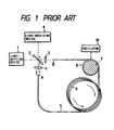
- The basic construction of a phase modulated fiber-optic gyroscope is described below with reference to Fig. 1. Phase modulation is produced from a piezoelectric device around which one end portion of the optical fiber cable in the sensor coil is wound. By picking up the first-order term of the modulated wave, the phase difference can be determined in the form of sinΔθ.
- Coherent light issuing from a light-
emitting device 1 is split into two beams by a beam splitter 2. One of the two beams is converged by a coupling lens 4 and launched into end A of an optical fiber cable 5. This beam is transmitted through the sensor coil 6 counterclockwise. The other beam is converged by a coupling lens 3, launched into end B of the optical fiber 5 and transmitted through the sensor coil 6 clockwise. - The greater part of the optical fiber cable 5 forms the sensor coil 6 and only the part close to end B is wound around the piezoelectric device to form a
phase modulation device 7. - An
oscillator 10 produces an oscillating voltage that causes the piezoelectric device to expand or contract. The phase modulating part 8 of the optical fiber cable is wound onto the piezoelectric device, so it will expand or contract together with the piezoelectric device to produce a light signal containing a modulated component. - The light beam transmitted clockwise through the phase modulating part 8 and the sensor coil 6 will emerge from end A, and the other beam transmitted counterclockwise through the sensor coil 6 and the phase modulating part 8 will emerge at end B. The emerging light beams are recombined by the beam splitter 2 and launched as a single beam into a light-receiving device 9, which performs square-law detection on the light of interference.
- Since the
phase modulation device 7 is located asymmetrically with respect to the fiber-optic cable 5, the light being transmitted clockwise is phase-modulated at a slightly different time than the light being transmitted counterclockwise. The time, T, required for the light to pass through the sensor coil 6 is given by:
phase modulation device 7 is positioned close to end B, the light being transmitted clockwise will be first phase-modulated before it is launched into the sensor coil 6. On the other hand, the light being transmitted counterclockwise passes through the sensor coil 6 before it is launched into thephase modulation device 7. - Let us write Q for the angular frequency of a modulating signal. Since the difference in time between the phase modulation caused by the
device 7 and the launching of the light into the light-receiving device 9 is T, the phase difference, φ, of the modulation signal contained in the light of interference is given by:
- As described above, the Sagnac effect introduces a phase difference of Δθ between the light transmitted clockwise and the light transmitted counterclockwise, and the phase modulation applied on the two light beams creates an additional phase difference of φ in the phase-modulated portion.
- If the amplitude due to the action of the
phase modulation device 7 is written as b, the field strength ER of the light transmitted clockwise is given by:

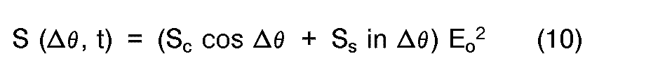
- The two light beams having these field strengths are subjected to square-law detection in the light-receiving device 9. The output of the light-receiving device, S(Δθ, t), is given by:

- If the dc component is eliminated, S(Δθ, t) can be rewritten in the form of a sum as follows:


- The foregoing description concerns the basic construction of a phase modulated fiber-optic gyroscope operating.
- When determining Δθ by detecting the fundamental component P, the modulation index ξ must be held constant. Otherwise, the value of J1 (ξ) will fluctuate. A method heretofore proposed for maintaining a constant value of modulation index consists of monitoring the second harmonic component Q to determine the value of J2(ξ). This method is described in Japanese Patent Application No. (JPA 61-124817) 59-244641. Signal Ω and signal 2Q which is an integral multiple of that signal are picked up from the drive circuit of a phase modulation device. The output of a light-receiving device is subjected to synchronous detection on the basis of these two signals. The detected output is passed through a low-pass filter to obtain a low-frequency component. The second harmonic component Q is:

- If the quantity of light from the light-emitting device is constant, Δe can be immediately determined from P(t) obtained by equation (16). In practice, however, the amplitude of the light, Eo, will fluctuate, so apparently different outputs will be produced for the same value of Δe on account of fluctuations in the quantity of the light.
- For the sake of simplicity, the foregoing discussion assumes that the two light beams, one transmitted clockwise and the other transmitted counterclockwise, have the same amplitude Eo. But this is not the case in practical situations. If it is necessary to distinguish the amplitudes of the two light beams, the amplitude of the light transmitted clockwise is written as E1 and that of the light transmitted counterclockwise is written as E2. In other words, the square of Eo appearing in the previous discussion should be read E1 E2.
- JP-A-60-135816 (the term "JP-A" as used herein means an "unexamined published Japanese patent application") proposes a control system that provides a constant dc component in output signal. But the problem associated with the quantity of reflected light is not discussed in this patent. By the term "reflected light" is meant those components of light which are reflected from the edge faces of lenses, fiber and other parts of the optical system. These components will not contribute to the measurement of angular velocity but simply become noise. In contrast, signal light passes through the sensor coil and contributes to the measurement of angular velocity.
- The light-receiving device receives both signal light and reflected light. The reflected light does not pass through the sensor coil. The control system described in JP-A-60-135816 assumes either the absence of reflected light or the presence of reflected light that will vary in the same way as does the signal light. Only in that case is valid the statement that holding the dc component constant is equivalent to controlling the amplitude of the light to be constant. In practice, however, a quantity of reflected light that is by no means negligible is launched into the light-receiving device. Reflected light will not fluctuate in the same way as does the signal light, or one may say that it will hardly fluctuate. The phase modulation index will also sometimes fluctuate. Therefore, holding the dc component constant does not necessarily result in a constant amplitude of the signal light.
- As already mentioned, the prior art fiber-optic gyroscope suffers the problem that substantial variations occur in the quantity of light that is issued from the light-emitting device to be launched into the optical fiber cable. In other words, substantial variations can occur in the amplitude Eo.Thus, apparently different outputs will be produced for the same angular velocity on account of these variations in the quantity of light.
- JP-A-61-147106 proposes a control system that is capable of maintaining a constant level of the dc component in the signal. JP-A-60-135816 already cited above proposes that the effects of variations in the quantity of light be cancelled by dividing the phase-modulated frequency component of the signal by the dc component. A phase-modulated fiber-optic gyroscope that operates with the second harmonic component controlled to be constant has also been proposed (see the already cited Japanese Patent Application No. 59-244641). The second harmonic component contains J2(ξ) and holding it constant was considered to be equivalent to controlling the phase modulation index to become constant. However, holding the dc component constant is by no means equivalent to controlling the quantity of light to be constant. The dc component contains Δe in the form of cosΔθ. The invention described in Japanese Patent Application No. 59-244641 adopts the approximation of Δθ≃0 and controls the dc component to become constant on the assumption that it is proportional to the intensity of the light issuing from the light-emitting device. However, Δe sometimes have such a great magnitude that it cannot be neglected. If Δe is substantial, the approximation of Δθ≃0 will produce inaccuracy.
- The approach of maintaining a constant value of the second harmonic component in order to hold the phase modulation index constant has the following problems.
- As equation (17) shows, the second harmonic component Q has not only the J2(ξ) term but also the cosΔθ term. The second harmonic component is held constant on the basis of the approximation that Δe is nearly equal to zero. However, this approximation is by no means exact if Δθ is great. This will eventually result in failure to maintain a constant value of the phase modulation index.
- Dividing the fundamental component by the dc component will cause the following additional problems. The dc component D of the light of interference which is the output of the light-receiving device can be written as:

- Assumption 1: There are no variations in the ratio of the quantity of the light transmitted clockwise to the quantity of the light transmitted counterclockwise;
- Assumption 2: There are no variations in the phase modulation index. If
assumption 1 holds,


- Further, determination of Δe from equation (222) involves quite complicated mathematical operations. This equation is by no means simple to deal with. One should also remember that the foregoing discussion disregards the quantity of the light inherent in the dc component.
- A control system in which the constant DC component is additionally measured is also known from the document Carl Cranz Gesellschaft e.V., Oberpfaffenhofen, Lehrgang: "Sensoren in inertialen Mess-und Navigationssystemen", gehalten in Braunschweig, DE, October 17-21, 1988; W. Auch: "Faseroptische Rotationssensoren",
Teil 1. - The gyroscope according to the preamble of
claim 1 is known from the EP-A-0 185 385. The phase modulation type fibre-optic gyroscope known from this reference has an improved output stability without a large increase in the number of basic components of the gyroscope system. The DC component of the output of a light detecting element which provides the two circulating beams is sensed and employed to control the output of the light emitting element so as to be constant. - It is the object of the present invention to provide a new phase modulation fibre-optic gyroscope which is improved over the prior art.
- This object is solved by the features indicated in the characterising part of
claim 1. - The fiber-optic gyroscope of the present invention may operate on the following principles:
- (1) the gyroscope which is either at rest or rotating at an adequately small angular velocity is recognized by a signal coming either from the gyroscope itself or from another sensor;
- (2) if the above condition is satisfied, the output of the light-emitting device is so controlled that the dc component of the output from the light-receiving device is held constant; and
- (3) if the above condition is satisfied, the phase modulation index is so controlled that the second harmonic component of the output from the light-receiving device is held constant.
-
- Fig. 1 shows the basic construction of a phase modulated prior art fiber-optic gyroscope;
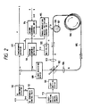
- Fig. 2 shows an example of the basic construction of the fiber-optic gyroscope of the present invention;
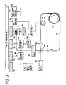
- Fig. 3 shows diagrammatically another embodiment of the present invention;
- Fig. 2 shows an example of the basic construction of the phase modulated fiber-optic gyroscope of the present invention. A light-emitting
device 101 is a light source of coherent light and may be composed of any apparatus such as a semiconductor laser, a super-luminescent diode or gas laser. Abeam splitter 102 divides the coherent light from the light-emittingdevice 101 into two light beams. The term "beam splitter" is used herein to mean a light dividing device in its broad sense. The two split light beams are converged bylenses optical fiber cable 105 at opposite ends A and B. Theoptical fiber cable 105 is made of a single-mode optical fiber and includes asensor coil 106 consisting of many turns of the optical fiber and aportion 108 wound around aphase modulation device 107. The sensor coil detects the angular velocity of rotation. - The
phase modulation device 107 comprises a piezoelectric device, typically in cylindrical form, that is provided with electrodes on an outside and an inside surface and around which the optical fiber cable is wound. Thephase modulation device 107 imparts periodic phase changes to the light being transmitted through the fiber-optic cable. - Between the electrodes are provided a modulation voltage of a frequency Q from a phase modulation device
excitation control unit 115. The amplitude of the applied voltage is proportional to the phase modulation index. - The light beam launched at end A is transmitted clockwise through the
sensor coil 106, whereas the light beam launched at end B is transmitted counterclockwise. The two light beams emerging from the fiber-optic cable are re-combined by thebeam splitter 102 and are launched as a single beam into a light-receivingdevice 109. The light-receivingdevice 109 detects the intensity of the light of interference and produces it as an output. The output from the light-receiving device contains the dc component D, the fundamental component P, the second harmonic component Q and harmonics of higher orders. - The dc component D is detected by a
dc component detector 110. The detected signal is sent to a dccomponent control unit 112. The dc component is used to stabilize the output of the light-emitting device but it does not always control the latter. It is used to control the output of the light-emitting device only if a stop signal U is applied from another sensor or when the final output S of the gyroscope per se is zero. - The dc
component control unit 112 supplies a light-emittingdevice control circuit 113 with a drive current W for the light-emitting device. Thecontrol unit 112 controls the dc component D of the output from the light-receiving device in such a way that said dc component is held constant when a stop signal U is supplied or when the final output S is zero. It should, however, be noted that the stop signal U need not refer to a "stop" in the strict sense of the term and a state close to "stop" may also be indicated. The same is true with the final output S and it need only be close to zero. - The dc
component control unit 112 stores the dc component D when the gyroscope is either stopped or in a state close to stop; it then compares the stored dc component with a predetermined value Do and supplies a command to the light-emitting deviceoutput control circuit 113 so that the stored dc component will approach the predetermined value Do. - The fundamental component P of the output from the light-receiving
device 109 is detected by thefundamental detector 117. A sync signal is supplied from the phase modulation deviceexcitation control unit 115. The second harmonic component Q of the output from the light-receivingdevice 109 is detected by a secondharmonic detector 111. The modulation signal from thecontrol unit 115 is doubled in amultiplier 120 to produce a sync signal. - The modulation index of the
control unit 115 is controlled in such a way as to provide a constant level of the second harmonic component. The modulation index is theoretically expressed by b but since it is proportional to £, may also be designated the modulation index. The second harmonic component is not always controlled to be constant. Only when a stop signal U is supplied from another sensor or if the final output S from the gyroscope is either equal or close to zero is the second harmonic component controlled to become equal to a predetermined value Qo. - Such an intermittent control is performed by a second
harmonic control unit 114. The gyroscope which is at rest or in a state very close to it is identified by the supply of either a stop signal from another sensor or a substantially zero output S from the gyroscope. The value of the second harmonic component Q in that instance is adopted by thecontrol unit 114 which compares it with Qo and supplies the modulation index ξ of the phase modulation deviceexcitation control unit 115 in such a way that the difference between Q and Qo will be minimized. - The fundamental component P appears as the output of the
fundamental detector 117, which serves as the final output S. This is equivalent to equation (16) except that the vibration term is eliminated:
- In the foregoing discussion, the second harmonic component is detected and controlled to be constant in order to maintain a constant level of the phase modulation index. It should, however, be noted that in place of the second harmonic component, the third or fourth harmonic component may be controlled to be constant in order to maintain a constant level of the phase modulation index. This is possible since all the harmonics of interest contain the phase modulation index.
- In the previous discussion of the operation of the fiber-optic gyroscope based on phase modulation, the amplitudes of the two light beams transmitted clockwise and counterclockwise were collectively written as Eo without being distinguished from each other. In the discussion that follows, the amplitude of the light transmitted clockwise is written as E1 and that of the light transmitted counterclockwise is written as E2. Thus, E0 2 appearing in the previous discussion should in all instances be read E1 E2.
- The dc component D of the output from the light-receiving device can be rewritten as:


dc component detector 110, the dccomponent control unit 112, the light-emitting deviceoutput control circuit 113, and other associated components shown in Fig. 4. - We now describe the control of the second harmonic component Q, which is given by:


- Fig. 3 shows another embodiment of the present invention which employs the construction shown in Fig. 2. The components which are the same as those shown in Fig. 2 are identified by like numerals and will not be described in detail.
- The
dc component detector 110 is supplied with the output from the light-receiving 109 and produces the dc component of said output as a voltage signal, which is converted to a digital signal in an A/D converter 122. - When the gyroscope receives a stop signal from another sensor or in response to a zero or nearly zero final output S from the gyroscope per se, the following operations are performed. A control signal for controlling the quantity of the light issuing from the light-emitting device in such a way that the dc component D becomes equal to the preset value Do is calculated and constructed. This control signal is converted to an analog signal in a D/
A converter 121 and supplied to the light-emitting deviceoutput control circuit 113. - When the gyroscope is rotating at fast speed, the control signal constructed for the previous case where the gyroscope was at rest is retained and delivered as an output. Since it is handled as a digital signal by a
digital processing unit 116, the control signal can be easily retained and continuously supplied as an output. - In response to this control signal, the light-emitting device
output control circuit 113 controls the quantity of the light emerging from the light-emitting device. - An
oscillator 118 generates a modulation signal having a frequency Q. The output of theoscillator 118 is fed to amultiplier 119 where it is amplified by an appropriate factor. The amplified phase modulation signal is applied to the electrodes of thephase modulation device 107. Hence, ξ or the modulation index b which is to be provided by thephase modulation device 107 can be freely adjusted by controlling the factor of amplification with themultiplier 119. - In response to the sync signal (f = Q) from the
oscillator 118, thefundamental detector 117 elicits the fundamental component P from the output of the light-receiving device. The fundamental component P is fed to an A/D converter 124 and thence supplied into thedigital processing unit 116. -
Multiplier 120 multiplies the phase modulation signal from theoscillator 118 to form a sync signal having a frequency of 2Q. In response to the sync signal (f = 2Q) from themultiplier 120, the secondharmonic detector 111 detects the second harmonic component Q of the output from the light-receiving device. The detected signal is fed to an A/D converter 125 where it is converted to a digital signal which is thereafter supplied to thedigital processing unit 116. - When the fiber-optic gyroscope is at rest or in a state very close to it, the
digital processing unit 116 recognizes this situation either by its own final output S or in response to a stop signal U supplied from another sensor. In the latter case, a state signal from another sensor is supplied into thedigital processing unit 116 through a statesignal detecting interface 126. Thedigital processing unit 116 then determines as to whether the applied state signal indicates that the gyroscope is at rest and if this is the case, a stop signal U is constructed. Alternatively, another sensor may itself produce a stop signal U when the gyroscope is at rest, which stop signal is then supplied into thedigital processing unit 116. Of course, the gyroscope may itself produce a final output S which is nearly equal to zero. - When the fiber-optic gyroscope is at rest or in a state very close to it, the
digital processing unit 116 performs the following two operations. First, it compares the dc component D with the preset reference Do and controls the output of the light-emitting device in such a way that the difference is minimized. The control signal is supplied into the light-emitting deviceoutput control unit 113 through the D/A converter 121. Second, the processing unit compares the second harmonic component Q with the preset reference Qo and controls the phase modulation index ξ in such a way that the difference is minimized. The control signal is supplied into themultiplier 119 through the D/A converter 123. - When the gyroscope is rotating at high speed, the values of the dc component and the second harmonic component for the previous case where the gyroscope was at rest are retained by the processing unit, which keeps supplying the respective values to the
control unit 113 and themultiplier 119. - The angular velocity of the rotating gyroscope can be determined from the fundamental component P.
Claims (3)
characterised in that
Applications Claiming Priority (7)
| Application Number | Priority Date | Filing Date | Title |
|---|---|---|---|
| JP57635/89 | 1989-03-08 | ||
| JP57637/89 | 1989-03-08 | ||
| JP57636/89 | 1989-03-08 | ||
| JP5763689A JPH02236113A (en) | 1989-03-08 | 1989-03-08 | Phase modulation optical fiber gyro |
| JP5763589A JPH02236112A (en) | 1989-03-08 | 1989-03-08 | Phase modulation optical fiber gyro |
| JP5763789A JPH02236114A (en) | 1989-03-08 | 1989-03-08 | Phase modulation optical fiber gyro |
| EP90104363A EP0386739B1 (en) | 1989-03-08 | 1990-03-07 | Phase modulated fiber-optic gyroscope |
Related Parent Applications (1)
| Application Number | Title | Priority Date | Filing Date |
|---|---|---|---|
| EP90104363.8 Division | 1990-03-07 |
Publications (3)
| Publication Number | Publication Date |
|---|---|
| EP0511684A2 true EP0511684A2 (en) | 1992-11-04 |
| EP0511684A3 EP0511684A3 (en) | 1993-01-13 |
| EP0511684B1 EP0511684B1 (en) | 1995-08-30 |
Family
ID=27296322
Family Applications (2)
| Application Number | Title | Priority Date | Filing Date |
|---|---|---|---|
| EP90104363A Expired - Lifetime EP0386739B1 (en) | 1989-03-08 | 1990-03-07 | Phase modulated fiber-optic gyroscope |
| EP92108242A Expired - Lifetime EP0511684B1 (en) | 1989-03-08 | 1990-03-07 | Phase modulated fibre-optic gyroscope |
Family Applications Before (1)
| Application Number | Title | Priority Date | Filing Date |
|---|---|---|---|
| EP90104363A Expired - Lifetime EP0386739B1 (en) | 1989-03-08 | 1990-03-07 | Phase modulated fiber-optic gyroscope |
Country Status (4)
| Country | Link |
|---|---|
| US (1) | US5048961A (en) |
| EP (2) | EP0386739B1 (en) |
| CA (1) | CA2011698C (en) |
| DE (2) | DE69022072T2 (en) |
Cited By (1)
| Publication number | Priority date | Publication date | Assignee | Title |
|---|---|---|---|---|
| EP0614069A1 (en) * | 1993-02-27 | 1994-09-07 | British Aerospace Public Limited Company | Laser gyroscopes |
Families Citing this family (12)
| Publication number | Priority date | Publication date | Assignee | Title |
|---|---|---|---|---|
| US5080489A (en) * | 1989-03-29 | 1992-01-14 | Kubota, Ltd. | Fiber optic gyroscope for detecting angular velocity of rotation using equivalent time sampling |
| US5196904A (en) * | 1990-12-31 | 1993-03-23 | Honeywell Inc. | Fiber optic gyroscope bias modulation amplitude determination |
| US5289257A (en) * | 1991-05-17 | 1994-02-22 | Mitsubishi Precision Co., Ltd. | Signal processing apparatus for optical gyro |
| US5412472A (en) * | 1992-01-30 | 1995-05-02 | Japan Aviation Electronics Industry Limited | Optical-interference type angular velocity or rate sensor having an output of improved linearity |
| US5283626A (en) * | 1992-04-17 | 1994-02-01 | Honeywell Inc. | Fiber optic gyroscope bias modulation amplitude determination with reset means |
| EP0569993B1 (en) * | 1992-05-14 | 1996-01-31 | Japan Aviation Electronics Industry, Limited | Optical-interference-type angular rate sensor |
| US6243167B1 (en) * | 1996-11-14 | 2001-06-05 | Talltec Technologies Holdings S.A. | Multimode fiber optic gyroscope |
| RU2142118C1 (en) * | 1998-06-29 | 1999-11-27 | Производственное объединение "Корпус" | Small-sized three-axes fiber-optical meter of angular velocity |
| DE10138154C2 (en) | 2001-08-03 | 2003-06-05 | Litef Gmbh | Method and device for increasing the long-term operational reliability of a fiber optic interferometer |
| RU2227272C2 (en) * | 2002-07-17 | 2004-04-20 | ФГУП ПО "Корпус" | Wide-range fiber-optical meter of angular velocity |
| US9354063B2 (en) * | 2014-04-30 | 2016-05-31 | Honeywell International Inc. | Systems and methods for providing intensity stabilization for a resonator fiber optic gyroscope |
| RU2626553C1 (en) * | 2016-05-19 | 2017-07-28 | Федеральное государственное казенное военное образовательное учреждение высшего образования "Военный учебно-научный центр Военно-воздушных сил "Военно-воздушная академия имени профессора Н.Е. Жуковского и Ю.А. Гагарина" (г. Воронеж) Министерства обороны Российской Федерации | Band amplifier |
Family Cites Families (6)
| Publication number | Priority date | Publication date | Assignee | Title |
|---|---|---|---|---|
| JPS60135816A (en) * | 1983-12-26 | 1985-07-19 | Sumitomo Electric Ind Ltd | Hikari fiber gyro |
| JPS61124817A (en) * | 1984-11-21 | 1986-06-12 | Agency Of Ind Science & Technol | Optical fiber gyrocompass according to phase modulation system |
| JPH0743263B2 (en) * | 1984-12-21 | 1995-05-15 | 工業技術院長 | Phase modulation optical fiber gyro |
| JPH0680405B2 (en) * | 1985-11-06 | 1994-10-12 | 株式会社東芝 | Light fiber gyro |
| US4796993A (en) * | 1987-04-13 | 1989-01-10 | Hitachi, Ltd. | Phase modulation type fiber optic gyroscope |
| US4883358A (en) * | 1987-09-02 | 1989-11-28 | Japan Aviation Electronics Industry Limited | Fiber optic gyro stabilized by harmonic components of detected signal |
-
1990
- 1990-03-07 US US07/489,556 patent/US5048961A/en not_active Expired - Fee Related
- 1990-03-07 CA CA002011698A patent/CA2011698C/en not_active Expired - Fee Related
- 1990-03-07 DE DE69022072T patent/DE69022072T2/en not_active Expired - Fee Related
- 1990-03-07 EP EP90104363A patent/EP0386739B1/en not_active Expired - Lifetime
- 1990-03-07 EP EP92108242A patent/EP0511684B1/en not_active Expired - Lifetime
- 1990-03-07 DE DE69009533T patent/DE69009533T2/en not_active Expired - Fee Related
Cited By (2)
| Publication number | Priority date | Publication date | Assignee | Title |
|---|---|---|---|---|
| EP0614069A1 (en) * | 1993-02-27 | 1994-09-07 | British Aerospace Public Limited Company | Laser gyroscopes |
| US5459575A (en) * | 1993-02-27 | 1995-10-17 | British Aerospace Plc | Laser fiber optic gyroscope having phase modulation |
Also Published As
| Publication number | Publication date |
|---|---|
| DE69022072T2 (en) | 1996-02-15 |
| DE69022072D1 (en) | 1995-10-05 |
| DE69009533D1 (en) | 1994-07-14 |
| EP0511684A3 (en) | 1993-01-13 |
| EP0511684B1 (en) | 1995-08-30 |
| US5048961A (en) | 1991-09-17 |
| EP0386739A3 (en) | 1990-12-19 |
| EP0386739A2 (en) | 1990-09-12 |
| CA2011698A1 (en) | 1990-09-08 |
| EP0386739B1 (en) | 1994-06-08 |
| DE69009533T2 (en) | 1994-09-29 |
| CA2011698C (en) | 1994-08-23 |
Similar Documents
| Publication | Publication Date | Title |
|---|---|---|
| US4765739A (en) | Fiber optical rotation sensor utilizing the Sagnac phase difference | |
| US5946097A (en) | Vibration rectification error reducer for fiber optic gyroscope | |
| EP0511684A2 (en) | Phase modulated fibre-optic gyroscope | |
| US7715014B2 (en) | Methods and systems for fiber optic gyroscopes vibration error suppression | |
| US5090810A (en) | Ring resonator gyroscope controlling two servo control loops based on the output of a single interference detector | |
| US5080489A (en) | Fiber optic gyroscope for detecting angular velocity of rotation using equivalent time sampling | |
| US6028668A (en) | Fiber optic gyroscope having improved readout and modulation index control | |
| EP0245118A2 (en) | Fibre optic gyroscopes | |
| EP0462580B1 (en) | Fiber optic gyro with self-diagnostic function | |
| EP0431474B1 (en) | Fiber optic gyro | |
| EP0416531A2 (en) | Serrodyne resonator fiber optic gyroscope and method for operating it | |
| US5148236A (en) | Demodulation reference signal source | |
| US5031988A (en) | Fiber optic gyro | |
| US5363195A (en) | Automatic gain calibration system for a phase modulator in a fiber optic gyro | |
| JPH05256769A (en) | Method and apparatus for measuring gas concentration | |
| US5196904A (en) | Fiber optic gyroscope bias modulation amplitude determination | |
| US5285257A (en) | Optic rotation sensing apparatus and related method including providing synchronous detection at a phase at which the AM noise is minimized | |
| CA2061772C (en) | Synchronous detector | |
| CA2061904C (en) | Phase modulated fiber optic gyro accommodating angular rate reversals | |
| EP0388530A1 (en) | Fibre-optic gyroscopes | |
| EP0946858B1 (en) | Accuracy of a fiber optic gyro | |
| EP0802397B1 (en) | Fiber optic gyroscope | |
| EP0492580B1 (en) | Fiber optic gyro | |
| CA2020379C (en) | Digital synthetic serrodyne for fiber optic gyroscope | |
| GB2227833A (en) | Fibre-optic gyroscope |
Legal Events
| Date | Code | Title | Description |
|---|---|---|---|
| PUAI | Public reference made under article 153(3) epc to a published international application that has entered the european phase |
Free format text: ORIGINAL CODE: 0009012 |
|
| AC | Divisional application: reference to earlier application |
Ref document number: 386739 Country of ref document: EP |
|
| AK | Designated contracting states |
Kind code of ref document: A2 Designated state(s): DE FR GB IT SE |
|
| PUAL | Search report despatched |
Free format text: ORIGINAL CODE: 0009013 |
|
| AK | Designated contracting states |
Kind code of ref document: A3 Designated state(s): DE FR GB IT SE |
|
| 17P | Request for examination filed |
Effective date: 19930303 |
|
| 17Q | First examination report despatched |
Effective date: 19941017 |
|
| GRAA | (expected) grant |
Free format text: ORIGINAL CODE: 0009210 |
|
| AC | Divisional application: reference to earlier application |
Ref document number: 386739 Country of ref document: EP |
|
| AK | Designated contracting states |
Kind code of ref document: B1 Designated state(s): DE FR GB IT SE |
|
| PG25 | Lapsed in a contracting state [announced via postgrant information from national office to epo] |
Ref country code: IT Free format text: LAPSE BECAUSE OF FAILURE TO SUBMIT A TRANSLATION OF THE DESCRIPTION OR TO PAY THE FEE WITHIN THE PRE;WARNING: LAPSES OF ITALIAN PATENTS WITH EFFECTIVE DATE BEFORE 2007 MAY HAVE OCCURRED AT ANY TIME BEFORE 2007. THE CORRECT EFFECTIVE DATE MAY BE DIFFERENT FROM THE ONE RECORDED.SCRIBED TIME-LIMIT Effective date: 19950830 |
|
| ET | Fr: translation filed | ||
| REF | Corresponds to: |
Ref document number: 69022072 Country of ref document: DE Date of ref document: 19951005 |
|
| PG25 | Lapsed in a contracting state [announced via postgrant information from national office to epo] |
Ref country code: SE Effective date: 19951130 |
|
| PLBE | No opposition filed within time limit |
Free format text: ORIGINAL CODE: 0009261 |
|
| STAA | Information on the status of an ep patent application or granted ep patent |
Free format text: STATUS: NO OPPOSITION FILED WITHIN TIME LIMIT |
|
| 26N | No opposition filed | ||
| PGFP | Annual fee paid to national office [announced via postgrant information from national office to epo] |
Ref country code: GB Payment date: 20000301 Year of fee payment: 11 |
|
| PGFP | Annual fee paid to national office [announced via postgrant information from national office to epo] |
Ref country code: DE Payment date: 20000306 Year of fee payment: 11 |
|
| PGFP | Annual fee paid to national office [announced via postgrant information from national office to epo] |
Ref country code: FR Payment date: 20000310 Year of fee payment: 11 |
|
| PG25 | Lapsed in a contracting state [announced via postgrant information from national office to epo] |
Ref country code: GB Free format text: LAPSE BECAUSE OF NON-PAYMENT OF DUE FEES Effective date: 20010307 |
|
| GBPC | Gb: european patent ceased through non-payment of renewal fee |
Effective date: 20010307 |
|
| PG25 | Lapsed in a contracting state [announced via postgrant information from national office to epo] |
Ref country code: FR Free format text: LAPSE BECAUSE OF NON-PAYMENT OF DUE FEES Effective date: 20011130 |
|
| REG | Reference to a national code |
Ref country code: FR Ref legal event code: ST |
|
| PG25 | Lapsed in a contracting state [announced via postgrant information from national office to epo] |
Ref country code: DE Free format text: LAPSE BECAUSE OF NON-PAYMENT OF DUE FEES Effective date: 20020101 |