EP0511595A1 - Flowmeter - Google Patents
Flowmeter Download PDFInfo
- Publication number
- EP0511595A1 EP0511595A1 EP92106986A EP92106986A EP0511595A1 EP 0511595 A1 EP0511595 A1 EP 0511595A1 EP 92106986 A EP92106986 A EP 92106986A EP 92106986 A EP92106986 A EP 92106986A EP 0511595 A1 EP0511595 A1 EP 0511595A1
- Authority
- EP
- European Patent Office
- Prior art keywords
- core
- measuring tube
- molded part
- powder
- molded
- Prior art date
- Legal status (The legal status is an assumption and is not a legal conclusion. Google has not performed a legal analysis and makes no representation as to the accuracy of the status listed.)
- Withdrawn
Links
Images


Classifications
-
- G—PHYSICS
- G01—MEASURING; TESTING
- G01F—MEASURING VOLUME, VOLUME FLOW, MASS FLOW OR LIQUID LEVEL; METERING BY VOLUME
- G01F1/00—Measuring the volume flow or mass flow of fluid or fluent solid material wherein the fluid passes through a meter in a continuous flow
- G01F1/56—Measuring the volume flow or mass flow of fluid or fluent solid material wherein the fluid passes through a meter in a continuous flow by using electric or magnetic effects
- G01F1/58—Measuring the volume flow or mass flow of fluid or fluent solid material wherein the fluid passes through a meter in a continuous flow by using electric or magnetic effects by electromagnetic flowmeters
- G01F1/586—Measuring the volume flow or mass flow of fluid or fluent solid material wherein the fluid passes through a meter in a continuous flow by using electric or magnetic effects by electromagnetic flowmeters constructions of coils, magnetic circuits, accessories therefor
Definitions
- the invention relates to a magnetic-inductive flow meter for liquids with a measuring tube carrying the liquid and an electromagnet for generating a low-frequency magnetic field in the measuring tube, the electromagnet having at least one excitation coil and a core surrounding the measuring tube.
- Flowmeters of this type use the induction principle, according to which a voltage is induced in the case of moving charge carriers by applying a magnetic field perpendicular to the direction of movement.
- the voltage is perpendicular to the direction of movement and perpendicular to the magnetic field and is tapped via appropriately arranged electrodes.
- This measuring voltage is proportional to the average speed, so that the volume or mass flow of a conductive liquid in the measuring tube can be determined with the aid of this voltage.
- Time-varying magnetic fields are preferably used. These are then either switched or change periodically with frequencies below 1 kHz. Line frequency magnetic fields are often used.
- An electromagnet with a core is used for generation.
- the core is usually made up of layered metal sheets, as is customary in the case of mains transformers.
- the core forms two opposite poles, between which the measuring tube is arranged in order to generate the magnetic field in the measuring tube.
- the magnetic losses are minimized by the core completely surrounding the measuring tube, so that the magnetic flux runs predominantly within the core.
- the assembly is complex, since initially flanges on the measuring tube z. B. must be positioned by welding and only then the core can be placed on the measuring tube.
- the disadvantage of large size is avoided in another known embodiment by the magnetic yoke using winding tapes, but here a complex manufacturing technology is to be realized.
- the invention has for its object to develop a flowmeter of the type mentioned in such a way that a simple adaptation to structural conditions and an optimization of the magnetic field is possible in a simple manner.
- the core is formed from a ferromagnetic powder, the powder particles of which are electrically insulated or poorly conductive to avoid eddy currents.
- the design as a molded part allows on the one hand an optimization of the magnetic field by a corresponding core geometry and on the other hand an adaptation to structural conditions in a simple manner. Furthermore, there is a simple and inexpensive manufacture. Appropriate selection of the ferromagnetic material achieves a high permeability and thus a high magnetic flux density.
- the air gap between the poles is expediently more than 5 mm.
- the core is formed from at least one molded part obtained by cold or hot pressing. Instead, it can also be provided that the core is formed from at least one molded part obtained by injection molding or sintering.
- the powder preferably consists essentially of Fe.
- Fe has the well-known advantage of high permeability.
- the ferromagnetic powder can be mixed with a plastic binder that isolates the powder particles. Practical tests have shown that about 1% by volume of plastic binder is sufficient to obtain sufficiently dimensionally stable cores with excellent electromagnetic properties by hot pressing between about 90 and 150 ° C.
- the powder can have up to 10% by weight of Si. This measure permanently reduces eddy currents that occur.
- a preferred embodiment is characterized in that the powder consists of about 95-98% by weight of Fe, up to 3% by weight of Si, the rest of the insulating material. On the one hand, this mixture has a high permeability and, on the other hand, shows only low losses due to eddy currents. It can also be provided that Fe is completely or partially replaced by Fe / Ni, as is known per se in transformer sheets, since this results in excellent magnetic properties.
- the insulating material can be a binder, for example, in order to obtain sufficient mechanical stability.
- the powder and / or the insulation consists at least partially of ferrimagnetic material. These materials are characterized by a relatively high permeability, but are generally not electrically conductive. Eddy currents in the molded part can thus be minimized in a simple manner.
- the insulation preferably consists of a thermoplastic, a thermoset, oxides, carbides, nitrides or the like. These materials provide good electrical insulation and lead to a mechanically very stable body during press molding. Resin can also be used as an insulation and connection material.
- the molded part is manufactured depending on the powder and insulating material used. It can be provided that the molded part is cold or hot pressed, manufactured under negative pressure and / or by sintering. In this way, the desired mechanical and magnetic properties of the molded part can be realized.
- the core has two, four or more inferences.
- the molded part is designed as an X-core with four inferences.
- the X core supplements the generally cylindrical shape of the excitation coil to form a cuboid. This results in an optimal use of space, especially when the flowmeter is installed in a cuboid housing.
- the molded part is designed as an M-core with two inferences or as a shell core.
- the guidance of the magnetic field is improved in that at least one pole with a pole shoe is adapted to the outer contour of the measuring tube.
- Space-saving training is also made possible in that the core is designed to accommodate a saddle coil.
- a composite technology can be used in such a way that the core is formed from nested laminated cores combined with molded parts.
- the poles and inferences can be cylindrical or conical. With a conical design and predetermined geometric relationships between the pole and the yoke, the stray field can be minimized in the region of the magnetic field generated.
- the molded body can also be removed from the mold more easily.
- a preferred embodiment is characterized in that the core is formed from at least two molded parts, in the parting plane of which the measuring tube is arranged. This enables a particularly simple assembly of the molded part on the measuring tube, since both parts of the electromagnet are joined together, including the measuring tube.
- the core can also, for. B. be formed as an M-core from a molded part.
- Optimal guidance of the magnetic flux in the core to achieve a high magnetic flux density in the measuring tube results from the fact that the measuring tube is arranged between two molded poles of the molded parts.
- the molded part preferably also has recesses, grooves or holes for fixing connecting lines.
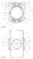
- the flow meter 1 has excitation coils 2 and a core 3.
- the coils 2 and the core 3 form an electromagnet which generates a magnetic field in a measuring tube 4.
- the core 3 consists of two molded parts 5, each of which has a pole 6.
- the core 3 surrounds the measuring tube 4, the poles 6 being arranged diametrically opposite one another with respect to the measuring tube 4.
- Each pole 6 is surrounded by one of the coils 2.
- the molded parts 5 are designed as X-cores and each have four inferences 7 designed as zygomatic bones, which rest against those of the other molded part 5 in a parting plane 8 and thus produce the magnetic flux from one pole 6 to the other within the core 3.
- both molded parts 5 are mirror-symmetrical, the axis of the measuring tube 4 being in the parting plane 8 and, accordingly, a simple assembly of the flow measuring device 1 being made possible.
- the coils 2 are used to generate a magnetic field perpendicular to the direction of movement of the liquid.
- a voltage proportional to the speed is induced perpendicular to the direction of movement and perpendicular to the magnetic field, which voltage is tapped and evaluated with the aid of the electrodes 9.
- the evaluation circuit is not shown.
- the use of a shaped core 3 allows a very variable design.
- the width of the flow measuring device 1, as can be seen in FIG. 3, is only determined by the transverse extent of the coil 2, which is in particular due to the design of the molded parts 5 as X-cores. This allows the construction of a very narrow flow meter 1.
- there is a very simple assembly of the flow meter 1 since the core 3 in the parting plane 8 makes it easy to insert the measuring tube 4 is possible so that flanges or other connecting elements can be positioned on the measuring tube before the flow meter 1 is assembled.
- FIG. 4a shows an M-core, which is preferably formed in one piece from a molded part 5 for a measuring tube 4 with small nominal widths.
- the molded part can, however, as indicated here, be divided in the axial plane of the measuring tube 4.
- FIG. 4b shows that the M core has only two inferences 7.
- Figure 5a shows a two-part shell core.
- the core 5 forms a circular cylinder arranged perpendicular to the axis of the measuring tube 4.
- this embodiment has large-scale conclusions 7 in cross section. This ensures a good return of the magnetic field.
- a very simple embodiment variant results from a U-shape of the core according to FIG. 6a.
- This embodiment in particular enables easy assembly, since the electromagnet can be pushed laterally onto the measuring tube.
- this embodiment can be formed either by a simple U-core with a yoke 7 or also by a half X-core (according to FIGS. 1 to 3) with two yokes 7.
- the half X-core has the advantage that the extension of the electromagnet is determined at least in one direction by the extension of the coil 2.
- FIG. 7a shows an embodiment which is particularly suitable for measuring tubes 4 with large nominal widths.
- the poles 6 have pole shoes 11, which are adapted to the outer contour of the measuring tube 4. This leads to a particularly good guidance of the magnetic field.
- the lower molded part 5 is designed so that the coil 2 is designed as a saddle coil. This allows a particularly space-saving construction of the electromagnet.
- a conventional solenoid 2 as shown in the upper half, can also be used.
- the core can have two or four inferences.
- the core 3 can be constructed from several molded parts or from molded parts in combination with layered laminated cores.
- FIG. 7b shows that in this embodiment, comparable to the X core, four inferences 7 ensure good magnetic inference.
Landscapes
- Physics & Mathematics (AREA)
- Engineering & Computer Science (AREA)
- Power Engineering (AREA)
- Electromagnetism (AREA)
- Fluid Mechanics (AREA)
- General Physics & Mathematics (AREA)
- Measuring Volume Flow (AREA)
Abstract
Description
Die Erfindung betrifft ein magnetisch-induktives Durchflußmeßgerät für Flüssigkeiten mit einem die Flüssigkeit führenden Meßrohr und einem Elektromagneten zur Erzeugung eines niederfrequenten Magnetfeldes im Meßrohr, wobei der Elektromagnet wenigstens eine Erregerspule und einen das Meßrohr umgebenden Kern aufweist.The invention relates to a magnetic-inductive flow meter for liquids with a measuring tube carrying the liquid and an electromagnet for generating a low-frequency magnetic field in the measuring tube, the electromagnet having at least one excitation coil and a core surrounding the measuring tube.
Derartige Durchflußmeßgeräte nützen das Induktionsprinzip, wonach bei bewegten Ladungsträgern durch Anlegen eines Magnetfeldes senkrecht zur Bewegungsrichtung eine Spannung induziert wird. Die Spannung liegt senkrecht zur Bewegungsrichtung und senkrecht zum Magnetfeld an und wird über entsprechend angeordnete Elektroden abgegriffen. Diese Meßspannung ist proportional zur mittleren Geschwindigkeit, so daß mit Hilfe dieser Spannung der Volumen- bzw. Massenstrom einer leitfähigen Flüssigkeit in dem Meßrohr bestimmt werden kann.Flowmeters of this type use the induction principle, according to which a voltage is induced in the case of moving charge carriers by applying a magnetic field perpendicular to the direction of movement. The voltage is perpendicular to the direction of movement and perpendicular to the magnetic field and is tapped via appropriately arranged electrodes. This measuring voltage is proportional to the average speed, so that the volume or mass flow of a conductive liquid in the measuring tube can be determined with the aid of this voltage.
Bevorzugt werden zeitlich variierende Magnetfelder verwendet. Diese sind dann entweder geschaltet oder wechseln periodisch mit Frequenzen unter 1 kHz. Vielfach werden netzfrequente Magnetfelder eingesetzt. Zur Erzeugung wird ein Elektromagnet mit einem Kern verwendet. Der Kern ist in der Regel aus geschichteten Blechen aufgebaut, wie dies bei Netztransformatoren üblich ist. Der Kern bildet zwei gegenüberliegende Pole, zwischen denen das Meßrohr angeordnet ist, um das Magnetfeld im Meßrohr zu erzeugen. Die magnetischen Verluste werden minimiert, indem der Kern das Meßrohr vollständig umgibt, so daß der magnetische Fluß überwiegend innerhalb des Kerns verläuft. Dies führt jedoch zu einer beträchtlichen Baugröße des Gerätes, insbesondere quer zum Meßrohr. Weiterhin ist die Montage aufwendig, da auf dem Meßrohr zunächst Flansche z. B. durch Schweißen positioniert werden müssen und erst anschließend der Kern auf dem Meßrohr aufgesetzt werden kann. Der Nachteil großer Baugröße wird bei einer anderen bekannten Ausführung vermieden, indem der magnetische Rückschluß über Wickelbänder erfolgt, doch ist hier eine aufwendige Fertigungstechnik zu verwirklichen.Time-varying magnetic fields are preferably used. These are then either switched or change periodically with frequencies below 1 kHz. Line frequency magnetic fields are often used. An electromagnet with a core is used for generation. The core is usually made up of layered metal sheets, as is customary in the case of mains transformers. The core forms two opposite poles, between which the measuring tube is arranged in order to generate the magnetic field in the measuring tube. The magnetic losses are minimized by the core completely surrounding the measuring tube, so that the magnetic flux runs predominantly within the core. However, this leads to a considerable size of the device, especially across the measuring tube. Furthermore, the assembly is complex, since initially flanges on the measuring tube z. B. must be positioned by welding and only then the core can be placed on the measuring tube. The disadvantage of large size is avoided in another known embodiment by the magnetic yoke using winding tapes, but here a complex manufacturing technology is to be realized.
Der Erfindung liegt die Aufgabe zugrunde, ein Durchflußmeßgerät der eingangs genannten Art dahingehend weiterzubilden, daß eine einfache Anpassung an bauliche Rahmenbedingungen und eine Optimierung des Magnetfeldes in einfacher Weise möglich ist.The invention has for its object to develop a flowmeter of the type mentioned in such a way that a simple adaptation to structural conditions and an optimization of the magnetic field is possible in a simple manner.
Die Aufgabe wird dadurch gelöst, daß der Kern aus einem ferromagnetischen Pulver geformt ist, dessen Pulverpartikel zur Vermeidung von Wirbelströmen elektrisch isolierend oder schlecht leitend miteinander verbunden sind.The object is achieved in that the core is formed from a ferromagnetic powder, the powder particles of which are electrically insulated or poorly conductive to avoid eddy currents.
Die Ausbildung als Formteil gestattet zum einen eine Optimierung des Magnetfeldes durch eine entsprechende Kerngeometrie und zum anderen eine Anpassung an bauliche Rahmenbedingungen in einfacher Weise. Weiterhin ergibt sich eine einfache und preiswerte Herstellung. Durch entsprechende Auswahl des ferromagnetischen Materials wird eine hohe Permeabilität und damit hohe magnetische Flußdichte realisiert. Der Luftspalt zwischen den Polen beträgt zweckmäßigerweise mehr als 5 mm.The design as a molded part allows on the one hand an optimization of the magnetic field by a corresponding core geometry and on the other hand an adaptation to structural conditions in a simple manner. Furthermore, there is a simple and inexpensive manufacture. Appropriate selection of the ferromagnetic material achieves a high permeability and thus a high magnetic flux density. The air gap between the poles is expediently more than 5 mm.
Eine hohe Festigkeit wird dadurch erreicht, daß der Kern aus wenigstens einem durch Kalt- oder Warmpressen erhaltenen Formteil gebildet ist. Statt dessen kann aber auch vorgesehen sein, daß der Kern aus wenigstens einem durch Spritzgießen oder Sintern erhaltenen Formteil gebildet ist.A high strength is achieved in that the core is formed from at least one molded part obtained by cold or hot pressing. Instead, it can also be provided that the core is formed from at least one molded part obtained by injection molding or sintering.
Vorzugsweise besteht das Pulver im wesentlichen aus Fe. Fe hat den bekannten Vorteil hoher Permeabilität. Das ferromagnetische Pulver kann mit einem die Pulverpartikel isolierenden Kunststoffbinder versetzt sein. Praktische Versuche haben gezeigt, daß bereits etwa 1 Vol.% Kunststoffbinder ausreicht, um durch Warmpressen zwischen etwa 90 und 150°C ausreichend formstabile Kerne mit ausgezeichneten elektromagnetischen Eigenschaften erhalten werden können.The powder preferably consists essentially of Fe. Fe has the well-known advantage of high permeability. The ferromagnetic powder can be mixed with a plastic binder that isolates the powder particles. Practical tests have shown that about 1% by volume of plastic binder is sufficient to obtain sufficiently dimensionally stable cores with excellent electromagnetic properties by hot pressing between about 90 and 150 ° C.
Zur Verringerung von Wirbelströmen kann das Pulver bis 10 Gew. % Si aufweist. Durch diese Maßnahme werden sonst auftretende Wirbelströme nachhaltig reduziert.To reduce eddy currents, the powder can have up to 10% by weight of Si. This measure permanently reduces eddy currents that occur.
Eine bevorzugte Ausführung zeichnet sich dadurch aus, daß das Pulver aus etwa 95 - 98 Gew. % Fe, bis zu 3 Gew. % Si, Rest isolierendes Material, besteht. Diese Mischung weist einerseits eine hohe Permeabilität auf und zeigt andererseits nur geringe Verluste durch Wirbelströme. Dabei kann auch vorgesehen sein, daß Fe ganz oder teilweise durch Fe/Ni, wie bei Trafoblechen an sich bekannt, ersetzt ist, da sich hiermit ausgezeichnete magnetische Eigenschaften ergeben. Das isolierende Material kann beispielsweise ein Binder sein, um eine ausreichende mechanische Stabilität zu erhalten.A preferred embodiment is characterized in that the powder consists of about 95-98% by weight of Fe, up to 3% by weight of Si, the rest of the insulating material. On the one hand, this mixture has a high permeability and, on the other hand, shows only low losses due to eddy currents. It can also be provided that Fe is completely or partially replaced by Fe / Ni, as is known per se in transformer sheets, since this results in excellent magnetic properties. The insulating material can be a binder, for example, in order to obtain sufficient mechanical stability.
In einer weiteren Ausführungsform ist vorgesehen, daß das Pulver und/oder die Isolierung zumindest teilweise aus ferrimagnetischem Material besteht. Diese Materialien zeichnen sich durch eine verhältnismäßig große Permeabilität aus, sind jedoch in allgemeinen elektrisch nicht leitfähig. Dadurch lassen sich in einfacher Weise Wirbelströme im Formteil minimieren.In a further embodiment it is provided that the powder and / or the insulation consists at least partially of ferrimagnetic material. These materials are characterized by a relatively high permeability, but are generally not electrically conductive. Eddy currents in the molded part can thus be minimized in a simple manner.
Bevorzugt besteht die Isolierung aus einem Thermoplast, einem Duroplast, aus Oxiden, Karbiden, Nitriden oder dergleichen. Diese Materialien bewirken eine gute elektrische Isolation und führen beim Preßformen zu einem mechanisch sehr stabilen Körper. Genauso kann auch Kunstharz als Isolationsund Verbindungsmaterial verwendet werden.The insulation preferably consists of a thermoplastic, a thermoset, oxides, carbides, nitrides or the like. These materials provide good electrical insulation and lead to a mechanically very stable body during press molding. Resin can also be used as an insulation and connection material.
Die Herstellung des Formteils erfolgt in Abhängigkeit vom verwendeten Pulver und Isoliermaterial. Es kann vorgesehen sein, daß das Formteil kalt- oder warmgepreßt, bei Unterdruck und/oder durch Sintern hergestellt ist. So lassen sich gewünschte mechanische und magnetische Eigenschaften des Formteils realisieren.The molded part is manufactured depending on the powder and insulating material used. It can be provided that the molded part is cold or hot pressed, manufactured under negative pressure and / or by sintering. In this way, the desired mechanical and magnetic properties of the molded part can be realized.
Zur Minimierung der magnetischen Verluste weist der Kern zwei, vier oder mehr Rückschlüsse auf.To minimize magnetic losses, the core has two, four or more inferences.
In bevorzugter Ausführung ist vorgesehen, daß das Formteil als X-Kern mit vier Rückschlüssen ausgebildet ist. Der X-Kern ergänzt dabei die im allgemeinen zylindrische Form der Erregerspule zu einem Quader. So ergibt sich eine optimale Raumausnutzung, insbesondere wenn ein Einbau des Durchflußmeßgerätes in ein quaderförmiges Gehäuse erfolgt.In a preferred embodiment it is provided that the molded part is designed as an X-core with four inferences. The X core supplements the generally cylindrical shape of the excitation coil to form a cuboid. This results in an optimal use of space, especially when the flowmeter is installed in a cuboid housing.
Alternative Ausführungsformen ergeben sich dadurch, daß das Formteil als M-Kern mit zwei Rückschlüssen oder als Schalenkern ausgebildet ist.Alternative embodiments result from the fact that the molded part is designed as an M-core with two inferences or as a shell core.
Gerade bei großen Nennweiten des Meßrohrs wird die Führung des Magnetfeldes dadurch verbessert, daß wenigstens ein Pol mit einem Polschuh an die Außenkontur des Meßrohrs angepaßt ist.Especially with large nominal diameters of the measuring tube, the guidance of the magnetic field is improved in that at least one pole with a pole shoe is adapted to the outer contour of the measuring tube.
Dabei wird zudem eine platzsparende Ausbildung dadurch ermöglicht, daß der Kern zur Aufnahme einer Sattelspule ausgebildet ist.Space-saving training is also made possible in that the core is designed to accommodate a saddle coil.
Bei großen Nennweiten des Außenrohrs kann eine Verbundtechnik derart angewendet werden, daß der Kern aus geschachtelten Blechpaketen kombiniert mit Formteilen gebildet ist.In the case of large nominal diameters of the outer tube, a composite technology can be used in such a way that the core is formed from nested laminated cores combined with molded parts.
Die Pole und Rückschlüsse können zylindrisch oder konisch ausgebildet sein. Bei einer konischen Ausbildung und vorgegebenen geometrischen Verhältnissen zwischen Pol und Rückschluß läßt sich eine Minimierung des Streufeldes im Bereich des erzeugten Magnetfeldes erreichen. Auch läßt sich der Formkörper einfacher entformen.The poles and inferences can be cylindrical or conical. With a conical design and predetermined geometric relationships between the pole and the yoke, the stray field can be minimized in the region of the magnetic field generated. The molded body can also be removed from the mold more easily.
Es ist insbesondere bei der Ausbildung als X-Kern vorgesehen, daß bei kleinen Nennweiten des Meßrohres die Erstreckung des Elektromagneten in einer Richtung senkrecht zur Achse des Meßrohres im wesentlichen durch die Ausdehnung der Erregerspule bestimmt ist. Dadurch ist es möglich, Durchflußmesser auch bei sehr eng liegenden Rohrleitungen anzuordnen.It is provided in particular in the design as an X-core that, in the case of small nominal diameters of the measuring tube, the extent of the electromagnet in a direction perpendicular to the axis of the measuring tube is essentially determined by the extension of the excitation coil. This makes it possible to arrange flow meters even with very narrow pipes.
Eine bevorzugte Ausführungsform zeichnet sich dadurch aus, daß der Kern aus wenigstens zwei Formteilen gebildet ist, in deren Trennebene das Meßrohr angeordnet ist. Dies ermöglicht eine besonders einfache Montage des Formteils auf dem Meßrohr, da beide Teile des Elektromagneten unter Einschluß des Meßrohres zusammengefügt werden. Der Kern kann aber auch z. B. als M-Kern aus einem Formteil gebildet sein.A preferred embodiment is characterized in that the core is formed from at least two molded parts, in the parting plane of which the measuring tube is arranged. This enables a particularly simple assembly of the molded part on the measuring tube, since both parts of the electromagnet are joined together, including the measuring tube. The core can also, for. B. be formed as an M-core from a molded part.
Eine optimale Führung des magnetischen Flusses im Kern zur Erzielung einer großen magnetischen Flußdichte im Meßrohr ergibt sich dadurch, daß das Meßrohr zwischen zwei angeformten Polen der Formteile angeordnet ist.Optimal guidance of the magnetic flux in the core to achieve a high magnetic flux density in the measuring tube results from the fact that the measuring tube is arranged between two molded poles of the molded parts.
Gerade bei mehrteiligen Ausführungen ergibt sich eine einfache Montage, wenn im Formteil Ausnehmungen für Verbindungselemente vorgesehen sind. Vorzugsweise weist das Formteil auch Ausnehmungen, Nuten oder Löcher zur Fixierung von Anschlußleitungen auf.Particularly in the case of multi-part designs, assembly is simple if recesses for connecting elements are provided in the molded part. The molded part preferably also has recesses, grooves or holes for fixing connecting lines.
Die Erfindung wird nachstehend anhand der Zeichnung mehrerer Ausführungsbeispiele näher erläutert. Es zeigen:
- Figur 1
- eine Seitenansicht eines ersten Ausführungsbeispiels quer zur Durchflußrichtung;
Figur 2- eine Seitenansicht des Gerätes nach Figur 1 in Durchflußrichtung;
Figur 3- eine Draufsicht auf die Trennebene des Elektromagneten nach Figur 1;
- Figur 4a bis 7a
- weitere Ausführungsbeispiele im Radialschnitt durch das Meßrohr; und
- Figur 4b bis 7b
- die Ausführungsbeispiele nach Figur 4a bis 7a im Schnitt durch die Trennebene der Elektromagnete.
- Figure 1
- a side view of a first embodiment transverse to the flow direction;
- Figure 2
- a side view of the device of Figure 1 in the flow direction;
- Figure 3
- a plan view of the parting plane of the electromagnet according to Figure 1;
- Figure 4a to 7a
- further embodiments in radial section through the measuring tube; and
- Figure 4b to 7b
- the embodiments of Figure 4a to 7a in section through the parting plane of the electromagnet.
Das Durchflußmeßgerät 1 nach Figur 1 weist Erregerspulen 2 und einen Kern 3 auf. Die Spulen 2 und der Kern 3 bilden einen Elektromagneten, der in einem Meßrohr 4 ein Magnetfeld erzeugt. Der Kern 3 besteht in dieser Ausführung aus zwei Formteilen 5, die jeweils einen Pol 6 aufweisen. Der Kern 3 umgibt das Meßrohr 4, wobei die Pole 6 bezüglich des Meßrohres 4 diametral gegenüberliegend angeordnet sind. Jeder Pol 6 ist von einer der Spulen 2 umgeben. Die Formteile 5 sind als X-Kerne ausgebildet und weisen jeweils vier als Jochbeine ausgebildete Rückschlüsse 7 auf, die in einer Trennebene 8 denen des jeweils anderen Formteils 5 anliegen und so den Magnetfluß von einem Pol 6 zum anderen innerhalb des Kerns 3 herstellen. In der dargestellten Ausführungsform sind beide Formteile 5 spiegelsymmetrisch ausgeführt, wobei die Achse des Meßrohres 4 in der Trennebene 8 liegt und dementsprechend eine einfache Montage des Durchflußmeßgerätes 1 ermöglicht wird.The flow meter 1 according to Figure 1 has
In Figur 3 ist in der Draufsicht das untere Preßformteil 5 des Durchflußmeßgerätes 1 mit Meßrohr 4 zu erkennen. Am Meßrohr 4 sind zwei Elektroden 9 zur Aufnahme einer durch das Magnetfeld induzierten Spannung angeordnet. In den Rückschlüssen 7 sind Ausnehmungen 10 zur Aufnahme von Verbindungselementen zum Zusammenfügen der beiden Preßformteile 5 vorgesehen.In Figure 3, the
Zur Bestimmung der Geschwindigkeit einer leitfähigen Flüssigkeit im Meßrohr 4 wird mit Hilfe der Spulen 2 ein Magnetfeld senkrecht zur Bewegungsrichtung der Flüssigkeit erzeugt. Senkrecht zur Bewegungsrichtung und senkrecht zum Magnetfeld wird eine geschwindigkeitsproportionale Spannung induziert, die mit Hilfe der Elektroden 9 abgegriffen und ausgewertet wird. Die Auswerteschaltung ist nicht dargestellt.To determine the speed of a conductive liquid in the measuring
Die Verwendung eines geformten Kerns 3 gestattet eine sehr variable Gestaltung. So wird die Breite des Durchflußmeßgeräts 1, wie Figur 3 zu entnehmen ist, lediglich durch die Quererstreckung der Spule 2 bestimmt, was insbesondere auf die Ausbildung der Formteile 5 als X-Kerne zurückzuführen ist. Dies gestattet die Konstruktion eines sehr schmal bauenden Durchflußmeßgerätes 1. Weiterhin ist es in einfacher Weise möglich, durch eine Optimierung der Kerngeometrie die Bildung von Streufeldern zwischen dem Pol 6 und den als Jochbeinen ausgebildeten Rückschlüssen 7 zu minimieren. Dies ist in der dargestellten Ausführung dadurch realisiert, daß die Jochbeine, wie Figur 1 und 2 zu entnehmen ist, konisch ausgebildet sind, so daß die Rückschlüsse 7 im Bereich der Trennebene 8 einen möglichst großen Abstand zu den Polen 6 und auch zu den Spulen 2 aufweisen. Weiterhin ergibt sich eine sehr einfache Montage des Durchflußmeßgerätes 1, da durch die Trennung des Kerns 3 in der Trennebene 8 ein einfaches Einlegen des Meßrohrs 4 möglich ist, so daß Flansche oder sonstige Verbindungselemente schon vor dem Zusammenbau des Durchflußmeßgerätes 1 am Meßrohr positioniert werden können.The use of a shaped
Für die folgenden Ausführungsbeispiele werden die gleichen Bezugszeichen wie beim ersten Ausführungsbeispiel verwendet.The same reference numerals as in the first exemplary embodiment are used for the following exemplary embodiments.
Figur 4a zeigt einen M-Kern, der bevorzugt für ein Meßrohr 4 mit kleinen Nennweiten aus einem Formteil 5 einstückig ausgebildet wird. Das Formteil kann aber auch, wie hier angedeutet, in der Axialebene des Meßrohres 4 geteilt sein. Figur 4b ist zu entnehmen, daß der M-Kern nur zwei Rückschlüsse 7 aufweist.Figure 4a shows an M-core, which is preferably formed in one piece from a molded
Figur 5a stellt einen zweigeteilten Schalenkern dar. Dabei bildet der Kern 5 einen senkrecht zur Achse des Meßrohres 4 angeordneten Kreiszylinder. Wie sich aus Figur 5b ergibt, weist diese Ausführung in Querschnitt großflächige Rückschlüsse 7 auf. So wird eine gute Rückführung des Magnetfeldes gewährleistet.Figure 5a shows a two-part shell core. The
Eine sehr einfache Ausführungsvariante ergibt sich bei einer U-Form des Kerns nach Figur 6a. Diese Ausführungsform ermöglicht insbesondere eine leichte Montage, da der Elektromagnet seitlich auf das Meßrohr aufgeschoben werden kann. Aus Figur 6b und Figur 6b' ist erkennbar, daß diese Ausführung entweder durch einen einfachen U-Kern mit einem Rückschluß 7 oder auch durch einen halben X-Kern (gemäß Fig. 1 bis 3) mit zwei Rückschlüssen 7 gebildet sein kann. Hierbei weist der halbe X-Kern den Vorteil auf, daß die Erstreckung des Elektromagnets zumindest in einer Richtung durch die Ausdehnung der Spule 2 bestimmt ist.A very simple embodiment variant results from a U-shape of the core according to FIG. 6a. This embodiment in particular enables easy assembly, since the electromagnet can be pushed laterally onto the measuring tube. From FIG. 6b and FIG. 6b 'it can be seen that this embodiment can be formed either by a simple U-core with a
Figur 7a zeigt eine Ausführungsform, die insbesondere für Meßrohre 4 mit großen Nennweiten geeignet ist. Hierbei weisen die Pole 6 Polschuhe 11 auf, die an die Außenkontur des Meßrohres 4 angepaßt sind. Hierdurch wird eine besonders gute Führung des Magnetfeldes realisiert. Das untere Formteil 5 ist so ausgebildet, daß die Spule 2 als Sattelspule ausgeführt ist. Dies gestattet eine besonders platzsparende Konstruktion des Elektromagneten. Alternativ kann jedoch auch eine herkömmliche Zylinderspule 2, wie in der oberen Hälfte dargestellt, verwendet werden. Der Kern kann zwei oder vier Rückschlüsse aufweisen. Bei dieser Ausführung kann der Kern 3 aus mehreren Formteilen oder auch aus Formteilen in Kombination mit geschichteten Blechpaketen aufgebaut sein. Figur 7b ist zu entnehmen, daß bei dieser Ausführungsform vergleichbar zum X-Kern vier Rückschlüsse 7 einen guten magnetischen Rückschluß gewährleisten.FIG. 7a shows an embodiment which is particularly suitable for measuring
Claims (28)
Applications Claiming Priority (2)
| Application Number | Priority Date | Filing Date | Title |
|---|---|---|---|
| DE4114137 | 1991-04-30 | ||
| DE19914114137 DE4114137A1 (en) | 1991-04-30 | 1991-04-30 | FLOW MEASURING DEVICE |
Publications (1)
| Publication Number | Publication Date |
|---|---|
| EP0511595A1 true EP0511595A1 (en) | 1992-11-04 |
Family
ID=6430704
Family Applications (1)
| Application Number | Title | Priority Date | Filing Date |
|---|---|---|---|
| EP92106986A Withdrawn EP0511595A1 (en) | 1991-04-30 | 1992-04-24 | Flowmeter |
Country Status (2)
| Country | Link |
|---|---|
| EP (1) | EP0511595A1 (en) |
| DE (1) | DE4114137A1 (en) |
Cited By (6)
| Publication number | Priority date | Publication date | Assignee | Title |
|---|---|---|---|---|
| ES2065861A1 (en) * | 1993-05-25 | 1996-07-16 | Contadores De Agua De Zaragoza | Magnetic measuring organ for fluid meters |
| WO1997041407A1 (en) * | 1996-04-26 | 1997-11-06 | Caledonian Control Technology Limited | Electromagnetic flowmeters |
| WO2006122878A1 (en) * | 2005-05-16 | 2006-11-23 | Endress+Hauser Flowtec Ag | Magnetoinductive flow meter and measuring tube for such a flow meter |
| US7798015B2 (en) | 2005-05-16 | 2010-09-21 | Endress + Hauser Flowtec Ag | Magneto-inductive flowmeter and measuring tube for such |
| WO2015036187A3 (en) * | 2013-09-11 | 2015-06-25 | Endress+Hauser Flowtec Ag | Magnetically inductive flow measuring device, coil core and field coll |
| EP3436786B1 (en) * | 2016-03-31 | 2022-05-04 | Micro Motion, Inc. | Polymeric magnetic flowmeter flow body assembly |
Families Citing this family (3)
| Publication number | Priority date | Publication date | Assignee | Title |
|---|---|---|---|---|
| DE4307424C2 (en) * | 1993-03-09 | 1997-07-31 | Mat Mischanlagentechnik Gmbh | Control method for the continuous production of a homogeneous dispersion, in particular suspension, and associated device |
| DE102005063150A1 (en) * | 2005-12-30 | 2007-07-05 | Endress + Hauser Flowtec Ag | Magnetic-inductive flow receiver for fluid flowing in pipe work, comprises measuring tube, which can be inserted into run of pipe work to conduct fluid and measuring electrode assembly for recording electric voltage induced in flowing fluid |
| DE102015109747A1 (en) * | 2015-06-18 | 2016-12-22 | Endress+Hauser Flowtec Ag | Magnetic-inductive flowmeter |
Citations (6)
| Publication number | Priority date | Publication date | Assignee | Title |
|---|---|---|---|---|
| US3636764A (en) * | 1969-10-30 | 1972-01-25 | Statham Instrument Inc | Electromagnet for blood flowmeters and the like |
| US3827298A (en) * | 1971-10-29 | 1974-08-06 | Hitachi Ltd | Electromagnetic flow meter |
| WO1986005873A1 (en) * | 1985-03-27 | 1986-10-09 | Rheometron Ag | Measuring sensor for magnetic-inductive flowmeter |
| EP0228883A1 (en) * | 1985-12-27 | 1987-07-15 | Aichi Tokei Denki Co., Ltd. | Magnetic field generating device for electromagnetic flowmeter of residual magnetization type |
| DE4019237A1 (en) * | 1989-06-16 | 1990-12-20 | Hitachi Ltd | ELECTROMAGNETIC FLOW METER |
| EP0418033A1 (en) * | 1989-09-12 | 1991-03-20 | Kabushiki Kaisha Toshiba | Electromagnetic flowmeter |
-
1991
- 1991-04-30 DE DE19914114137 patent/DE4114137A1/en not_active Withdrawn
-
1992
- 1992-04-24 EP EP92106986A patent/EP0511595A1/en not_active Withdrawn
Patent Citations (6)
| Publication number | Priority date | Publication date | Assignee | Title |
|---|---|---|---|---|
| US3636764A (en) * | 1969-10-30 | 1972-01-25 | Statham Instrument Inc | Electromagnet for blood flowmeters and the like |
| US3827298A (en) * | 1971-10-29 | 1974-08-06 | Hitachi Ltd | Electromagnetic flow meter |
| WO1986005873A1 (en) * | 1985-03-27 | 1986-10-09 | Rheometron Ag | Measuring sensor for magnetic-inductive flowmeter |
| EP0228883A1 (en) * | 1985-12-27 | 1987-07-15 | Aichi Tokei Denki Co., Ltd. | Magnetic field generating device for electromagnetic flowmeter of residual magnetization type |
| DE4019237A1 (en) * | 1989-06-16 | 1990-12-20 | Hitachi Ltd | ELECTROMAGNETIC FLOW METER |
| EP0418033A1 (en) * | 1989-09-12 | 1991-03-20 | Kabushiki Kaisha Toshiba | Electromagnetic flowmeter |
Non-Patent Citations (2)
| Title |
|---|
| PATENT ABSTRACTS OF JAPAN vol. 12, no. 450 (C-547)25. November 1988 & JP-A-63 176 446 ( TOKIN CORP ) 20. Juli 1988 * |
| PATENT ABSTRACTS OF JAPAN vol. 7, no. 20 (M-188)26. Januar 1983 & JP-A-57 174 401 ( FUJITSU ) 27. Oktober 1982 * |
Cited By (6)
| Publication number | Priority date | Publication date | Assignee | Title |
|---|---|---|---|---|
| ES2065861A1 (en) * | 1993-05-25 | 1996-07-16 | Contadores De Agua De Zaragoza | Magnetic measuring organ for fluid meters |
| WO1997041407A1 (en) * | 1996-04-26 | 1997-11-06 | Caledonian Control Technology Limited | Electromagnetic flowmeters |
| WO2006122878A1 (en) * | 2005-05-16 | 2006-11-23 | Endress+Hauser Flowtec Ag | Magnetoinductive flow meter and measuring tube for such a flow meter |
| US7798015B2 (en) | 2005-05-16 | 2010-09-21 | Endress + Hauser Flowtec Ag | Magneto-inductive flowmeter and measuring tube for such |
| WO2015036187A3 (en) * | 2013-09-11 | 2015-06-25 | Endress+Hauser Flowtec Ag | Magnetically inductive flow measuring device, coil core and field coll |
| EP3436786B1 (en) * | 2016-03-31 | 2022-05-04 | Micro Motion, Inc. | Polymeric magnetic flowmeter flow body assembly |
Also Published As
| Publication number | Publication date |
|---|---|
| DE4114137A1 (en) | 1992-11-05 |
Similar Documents
| Publication | Publication Date | Title |
|---|---|---|
| EP0649005B1 (en) | Electromagnetic flow sensors | |
| DE2424131C3 (en) | throttle | |
| EP2463869A1 (en) | Inductive component with improved core properties | |
| DE2040682B2 (en) | Inductive flowmeter transducer for pipe flange mounting - has screened magnet and coil embedded in plastics insulating tube | |
| DE102015101211A1 (en) | THROTTLE | |
| DE2918483C2 (en) | Measuring transducer for potential-free measurement of currents or voltages | |
| DE102012014266A1 (en) | Magnetic-inductive flowmeter | |
| EP0511595A1 (en) | Flowmeter | |
| EP1756531B1 (en) | Magnetically inductive flow rate sensor | |
| EP0069865B1 (en) | Electrodynamic movable head | |
| EP2479541B1 (en) | Magnetic circuit for an electro-magnetic flowmeter | |
| DE102004063020B4 (en) | Magnetic-inductive flowmeter | |
| DE2603367C3 (en) | Magnetic pickup | |
| DE102009001413A1 (en) | Coil assembly for use in magnetic inductive flow-meter used in e.g. hardening system for measuring flow of water, has flat planar coupling plates, where field line density in plates is smaller than field line density in coil cores | |
| EP2867906B1 (en) | Inductive component | |
| EP1048932A1 (en) | Magnetic position sensor, as well as a process for its manufacture, and its application | |
| WO1997012207A9 (en) | Inductive flow meter | |
| DE2925654A1 (en) | TRAVELERS | |
| DE19515402C1 (en) | Oscillating piston pump with working piston held spring-loaded in output position | |
| DE2928617A1 (en) | Pressure sensor, esp. for measuring speed of diesel engines - where flux gate magnetometer measures elastic deformation of soft magnetic housing through which fuel flows | |
| EP1688710A1 (en) | Method for determining a displacement with an inductive position sensor and position sensor as such | |
| DE10322082A1 (en) | Magnetic inductive sensor for measuring flow of fluid through pipe has short length of pipe with two saddle-shaped field coils on outside, with ferromagnetic coupling elements | |
| DE2009513A1 (en) | Inductive flow meter with ferrous return | |
| DE2104394A1 (en) | Inductive flow meter for flowing media | |
| DE2411139C3 (en) | Inductive transducer for contactless detection of the distance between two objects |
Legal Events
| Date | Code | Title | Description |
|---|---|---|---|
| PUAI | Public reference made under article 153(3) epc to a published international application that has entered the european phase |
Free format text: ORIGINAL CODE: 0009012 |
|
| AK | Designated contracting states |
Kind code of ref document: A1 Designated state(s): DE DK FR GB IT NL SE |
|
| 17P | Request for examination filed |
Effective date: 19921208 |
|
| 17Q | First examination report despatched |
Effective date: 19940321 |
|
| STAA | Information on the status of an ep patent application or granted ep patent |
Free format text: STATUS: THE APPLICATION IS DEEMED TO BE WITHDRAWN |
|
| 18D | Application deemed to be withdrawn |
Effective date: 19950617 |