EP0510865A2 - Television camera equipped with continuously-variable-speed electronic shutter function - Google Patents
Television camera equipped with continuously-variable-speed electronic shutter function Download PDFInfo
- Publication number
- EP0510865A2 EP0510865A2 EP92303339A EP92303339A EP0510865A2 EP 0510865 A2 EP0510865 A2 EP 0510865A2 EP 92303339 A EP92303339 A EP 92303339A EP 92303339 A EP92303339 A EP 92303339A EP 0510865 A2 EP0510865 A2 EP 0510865A2
- Authority
- EP
- European Patent Office
- Prior art keywords
- shutter
- video
- amount
- unit
- signal
- Prior art date
- Legal status (The legal status is an assumption and is not a legal conclusion. Google has not performed a legal analysis and makes no representation as to the accuracy of the status listed.)
- Granted
Links
Images

Classifications
-
- H—ELECTRICITY
- H04—ELECTRIC COMMUNICATION TECHNIQUE
- H04N—PICTORIAL COMMUNICATION, e.g. TELEVISION
- H04N23/00—Cameras or camera modules comprising electronic image sensors; Control thereof
- H04N23/70—Circuitry for compensating brightness variation in the scene
- H04N23/72—Combination of two or more compensation controls
Definitions
- the present invention relates to a television camera equipped with a continuously-variable-speed electronic shutter function which is used for successively photographing or picking up a moving object or the like.
- the prior art shutter-equipped television camera belonging to the above category has such an arrangement as shown in Fig. 1 which is disclosed in Japanese Utility Model Laid-open No. Showa 64-29967(1989).
- Fig. 1 an optical lens 11 focuses the image of an object on a solid-state image pick-up device (image sensor) 12.
- a driving circuit 13 drives the image sensor 12 in a television system, and a shutter driving circuit 14 controls the photo-sensing time of the image sensor 12.
- a sampling circuit 15 converts the output from the solid-state image sensor 12 into a video signal which is supplied to an average level detecting circuit 16 and an amplifier 17.
- the average level detecting circuit 16 detects the average level of the video signal and supplies the corresponding signal to the shutter driving circuit 14.
- AGC automatic gain controlling circuit
- Fig. 1 when the brightness of a subject for the optical lens 11 changes, the output from the solid-state image sensor 12 changes. This leads to a change in the video signal output from the sampling circuit 15.
- the average level detecting circuit 16 detects this change as an average level and the corresponding control signal to the shutter driving circuit 14 to control the photo-sensing time of the solid-state image sensor 12.
- the amplifier 17 and AGC 18 amplify the video signal output from the sampling circuit 15 so it is maintained at a predetermined level; the amplified signal is supplied to the succeeding amplifier 19.
- the prior art shutter-equipped television camera can automatically adjust the photo-sensing degree or sensitivity of the image sensor 12 in accordance with a change in the brightness of the subject.
- the prior art shutter-equipped television camera in which the shutter driving circuit 14 makes control with a reduced number of steps using an up/down counter and an ROM with a low-accuracy shutter number, cannot also enhance the accuracy of the average level detecting circuit 16 and hence cannot responds to a change in the brightness of the subject to its extremity.
- An object of the present invention is to solve the problem of the prior art and to provide an excellent variable-shutter-equipped television camera which can respond to a change in the brightness of a subject with high accuracy and at high speed and holds a video signal at a predetermined level.
- Another object of the present invention is to provide an excellent variable-shutter-equipped television camera which has the above performance and also can hold the video signal at a predetermined level so that noise due to a shutter pulse does not invade the video signal.
- control is made in both AGC mode and shutter mode.
- the gain of the amplifier is fixed.
- the shutter mode an optimum estimated shutter amount is calculated on the basis of the video signal level detected for each field and the corresponding shutter amount and a target value of the video signal level, and the estimated shutter amount is supplied to a shutter pulse generating unit to drive the shutter-equipped image sensor with a continuously-variable-speed electronic shutter function.
- an optimum estimated shutter amount is calculated on the basis of the video signal level modified by a corrected gain of the detected video signal level and the corresponding shutter amount and a target value of the video signal level.
- the normal AGC control is not made, but the optimum shutter amount can be immediately calculated on the basis of the video signal level and the corresponding shutter amount and the target shutter amount, and the video signal can be placed at a predetermined level with high accuracy.
- the video signal can be placed at a predetermined level without loosing the performance of high speed and high accuracy so that noise due to a shutter pulse does not invade the video signal.
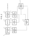
- Fig. 2 shows the arrangement of the first embodiment of the present invention.
- numeral 1 denotes an optical lens system which focuses the image of a subject on a shutter-equipped CCD 2 which is a solid-state image sensor.
- Numeral 3 denotes an amplifier which amplifies the image signal from the shutter-equipped CCD and supplies the amplified signal to a signal processing unit 4.
- Numeral 5 denotes a shutter pulse generating unit which determines the photo-sensing time of the shutter-equipped CCD 2.
- Numeral 6 denotes a gain control unit the control mode of which is changed to AGC control or fixed gain amplifying control on the basis of the signal from a control mode decision unit 9.
- Numeral 7 denotes a video level detecting unit which can obtain the level of the video signal during one field for each field period and supplies the corresponding signal to a gain control unit 6 and a shutter control unit 8.
- the manner of detecting the level of the video signal in the video level detecting unit 7 is classified into averaging the video signal during one field and detecting its peak value. From another viewpoint, it can be also classified into detecting the video signal over an entire field of image and detecting it at a predetermined detecting point (a part of the field of image). This detecting manner can be applied to averaging the video signal in the remaining area other than the area where the video signal level exceeds a predetermined numerical value.
- Numeral 8 denotes a shutter control unit which immediately calculates an optimum shutter amount on the basis of the signal output from the video level detecting unit 7 and the current shutter amount in the shutter-equipped CCD 2 corresponding to the signal using the following equation (1), thereby supplying it to the shutter pulse generating circuit 5 so as to hold the history of the shutter amount outputted.
- the optical lens system 1 receives the light from a subject, it focuses the image of the subject on the shutter-equipped CCD 2.
- the shutter-equipped CCD 2 supplies the optical signal, after subjected to charge sweeping by the shutter pulse generating unit 5, to the amplifier 3 as a video signal.
- the signal processing unit 4 processes the video signal for each of pixels included in a field-divided block.
- the video level detecting unit 7 selects a field area on the basis of the video level of each pixel in the field-divided, and calculates the video level for each field by averaging of the video level at the selected field area or detection of its peak or on the basis of data resulting from predetermined information.
- the calculated result is supplied to the gain control unit 6, the shutter control unit 8 and the control mode decision unit 9.
- the control mode decision unit 9 sets the control mode for the shutter mode on the basis of the shutter amount from the shutter control unit 8 and the video level signal from the video level detecting unit 7.
- the shutter control unit 8 immediately calculates an optimum estimated shutter by Equation (1) on the basis of the calculated video level, the corresponding current shutter amount and the target value of the video level, and holds the estimated shutter amount for a necessary time so that the current shutter amount corresponding to the control at issue can be obtained.
- the shutter pulse generating unit 5 supplies to the shutter-equipped CCD 2 a shutter pulse corresponding to the estimated shutter amount.
- the estimated shutter amount can be reflected on the video output.
- control mode decision unit 9 sets the control mode for the AGC mode so that the amplifier 3 and the gain control unit 6 operate as an AGC. If the video level is excessively high, the control mode decision unit 9 changes the control mode from the AGC mode to the shutter mode.
- the shutter control unit 8 holds the past estimated shutter. For this reason, the video level can be detected using the signal after amplified or gamma-corrected (not shown) so that the shutter amount of the video level at issue can be caused to corresponds to each filed.
- the optimum estimated shutter amount can be immediately calculated from Equation (1), even if the amount of light incident from the subject changes continuously for each field, any particular sensor is not required but the video level can be precisely controlled to provide the same target level individually from adjacent fields. Thus, the video level can always held precisely at a predetermined level.
- control mode decision unit 9 since the control mode decision unit 9 always catch the AGC amount, shutter amount and video level, the areas to be allotted to the AGC mode control and shutter mode control can be clearly separated. Thus, the subject having a wide range of brightness can be photographed or sensed under optimum control.
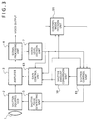
- Fig. 3 shows the arrangement of the second embodiment according to the present invention.
- like reference numerals designate like parts in Fig. 2.
- numeral 81 denotes a shutter control unit which has a new function in addition to the function of the shutter control unit in Fig. 2. Namely, the shutter control unit 81 can separate a minute shutter amount from the estimated shutter amount calculated from Equation (1) so that the shutter pulse does not appear during a horizontal video period. The shutter control unit 81 can also previously subtract from the video level a level amount corresponding to the above minute shutter amount as a correction gain component for the amplifier 3. The minute shutter amount is supplied to a shutter amount conversion unit 10.
- the shutter amount conversion unit 10 can calculate a correction gain component ⁇ g for the amplifier 3 on the basis of the minute control unit and the current shutter amount using Equation (2) and supplies its output to a gain control conversion unit 61.
- the shutter control unit 81 calculates an estimated shutter amount from Equation (1) so as to separate a minute shutter amount so that any shutter pulse does not appear during a horizontal video period.
- the estimated shutter amount is supplied to the shutter pulse generating unit 5 whereas the minute shutter amount is supplied to the shutter amount conversion unit 10. If the shutter amount is so much that some shutter pulse appears during a vertical blanking period, the shutter control unit 81 determines the estimated shutter amount so that the minute shutter amount to be separated does not become much.
- the shutter pulse generating unit 5 can always generate pulses during the vertical and horizontal blanking period in accordance with the estimated shutter amount to control the shutter-equipped CCD 2.
- the gain control unit 61 reduces the gain of the amplifier 3 from the predetermined fixed gain by the correction gain amount. This operation is always controlled by one field behind field the video signal when controlled by the estimated shutter amount.
- the video level can be controlled by the shutter amount which is derived from the signal obtained when the video level detected by the video level detecting unit 7 is modified by the shutter control unit 81.
- the shutter control unit 81 separates the minute shutter amount in calculating the estimated shutter amount using Equation (1).
- the amplifier 3, therefore, can compensate for the limited function of the shutter pulse generating unit 5. As a result, this embodiment can precisely hold the video signal level at a fixed level without being affected by any shutter pulse.
Abstract
Description
- The present invention relates to a television camera equipped with a continuously-variable-speed electronic shutter function which is used for successively photographing or picking up a moving object or the like.
- The prior art shutter-equipped television camera belonging to the above category has such an arrangement as shown in Fig. 1 which is disclosed in Japanese Utility Model Laid-open No. Showa 64-29967(1989). In Fig. 1, an
optical lens 11 focuses the image of an object on a solid-state image pick-up device (image sensor) 12. Adriving circuit 13 drives theimage sensor 12 in a television system, and ashutter driving circuit 14 controls the photo-sensing time of theimage sensor 12. Asampling circuit 15 converts the output from the solid-state image sensor 12 into a video signal which is supplied to an averagelevel detecting circuit 16 and anamplifier 17. The averagelevel detecting circuit 16 detects the average level of the video signal and supplies the corresponding signal to theshutter driving circuit 14. Theamplifier 17, the gain of which is controlled by an automatic gain controlling circuit (simply referred to as AGC), amplifies the video signal to a predetermined level to be supplied to a succeedingamplifier 19. - The operation of the above prior art will be explained below. In Fig. 1, when the brightness of a subject for the
optical lens 11 changes, the output from the solid-state image sensor 12 changes. This leads to a change in the video signal output from thesampling circuit 15. The averagelevel detecting circuit 16 detects this change as an average level and the corresponding control signal to theshutter driving circuit 14 to control the photo-sensing time of the solid-state image sensor 12. Theamplifier 17 andAGC 18 amplify the video signal output from thesampling circuit 15 so it is maintained at a predetermined level; the amplified signal is supplied to the succeedingamplifier 19. - In this way, the prior art shutter-equipped television camera can automatically adjust the photo-sensing degree or sensitivity of the
image sensor 12 in accordance with a change in the brightness of the subject. - However, the prior art shutter-equipped television camera, in which the
shutter driving circuit 14 makes control with a reduced number of steps using an up/down counter and an ROM with a low-accuracy shutter number, cannot also enhance the accuracy of the averagelevel detecting circuit 16 and hence cannot responds to a change in the brightness of the subject to its extremity. - An object of the present invention is to solve the problem of the prior art and to provide an excellent variable-shutter-equipped television camera which can respond to a change in the brightness of a subject with high accuracy and at high speed and holds a video signal at a predetermined level.
- Another object of the present invention is to provide an excellent variable-shutter-equipped television camera which has the above performance and also can hold the video signal at a predetermined level so that noise due to a shutter pulse does not invade the video signal.
- In order to attain the above object, in accordance with the present invention, control is made in both AGC mode and shutter mode. Specifically, in the AGC mode, the gain of the amplifier is fixed. On the other hand, in the shutter mode, an optimum estimated shutter amount is calculated on the basis of the video signal level detected for each field and the corresponding shutter amount and a target value of the video signal level, and the estimated shutter amount is supplied to a shutter pulse generating unit to drive the shutter-equipped image sensor with a continuously-variable-speed electronic shutter function.
- Further, in accordance with the present invention, in the shutter mode, an optimum estimated shutter amount is calculated on the basis of the video signal level modified by a corrected gain of the detected video signal level and the corresponding shutter amount and a target value of the video signal level.
- In this way, in accordance with the present invention, in the shutter mode, the normal AGC control is not made, but the optimum shutter amount can be immediately calculated on the basis of the video signal level and the corresponding shutter amount and the target shutter amount, and the video signal can be placed at a predetermined level with high accuracy.
- Further, in accordance with the present invention, since gain control of the amplifier can be engaged with shutter control, the video signal can be placed at a predetermined level without loosing the performance of high speed and high accuracy so that noise due to a shutter pulse does not invade the video signal.
- The above and other objects and features of the present invention will be more apparent from the following description taken in conjunction with the accompanying drawings.
-
- Fig. 1 is a schematic block diagram of the prior art television camera equipped with a variable shutter;
- Fig. 2 is a schematic block diagram of the television camera equipped with a variable shutter according to one embodiment of the present invention; and
- Fig. 3 is a schematic block diagram of the television camera equipped with a continuously-variable-speed electronic shutter function.
- Fig. 2 shows the arrangement of the first embodiment of the present invention. In Fig. 2,
numeral 1 denotes an optical lens system which focuses the image of a subject on a shutter-equippedCCD 2 which is a solid-state image sensor. Numeral 3 denotes an amplifier which amplifies the image signal from the shutter-equipped CCD and supplies the amplified signal to asignal processing unit 4. Numeral 5 denotes a shutter pulse generating unit which determines the photo-sensing time of the shutter-equippedCCD 2. Numeral 6 denotes a gain control unit the control mode of which is changed to AGC control or fixed gain amplifying control on the basis of the signal from a controlmode decision unit 9. Numeral 7 denotes a video level detecting unit which can obtain the level of the video signal during one field for each field period and supplies the corresponding signal to again control unit 6 and ashutter control unit 8. The manner of detecting the level of the video signal in the videolevel detecting unit 7 is classified into averaging the video signal during one field and detecting its peak value. From another viewpoint, it can be also classified into detecting the video signal over an entire field of image and detecting it at a predetermined detecting point (a part of the field of image). This detecting manner can be applied to averaging the video signal in the remaining area other than the area where the video signal level exceeds a predetermined numerical value. An application thereof is the case where light such as spot light is incident to a part of a field of image at a point in time. Numeral 8 denotes a shutter control unit which immediately calculates an optimum shutter amount on the basis of the signal output from the videolevel detecting unit 7 and the current shutter amount in the shutter-equippedCCD 2 corresponding to the signal using the following equation (1), thereby supplying it to the shutterpulse generating circuit 5 so as to hold the history of the shutter amount outputted.

- H₁
- : estimated shutter amount
- H₀
- : current shutter amount
- ΔH₁
- : correction shutter amount
- ave₀
- : video level
- m
- : target value of the video level
- k
- : coefficient
- The operation of the video camera according to this embodiment will be explained below. When the
optical lens system 1 receives the light from a subject, it focuses the image of the subject on the shutter-equippedCCD 2. The shutter-equippedCCD 2 supplies the optical signal, after subjected to charge sweeping by the shutterpulse generating unit 5, to theamplifier 3 as a video signal. Thesignal processing unit 4 processes the video signal for each of pixels included in a field-divided block. The videolevel detecting unit 7 selects a field area on the basis of the video level of each pixel in the field-divided, and calculates the video level for each field by averaging of the video level at the selected field area or detection of its peak or on the basis of data resulting from predetermined information. The calculated result is supplied to thegain control unit 6, theshutter control unit 8 and the controlmode decision unit 9. - Then, in the state where the continuously-variable-speed electronic shutter has been holded the predetermined position, the control
mode decision unit 9 sets the control mode for the shutter mode on the basis of the shutter amount from theshutter control unit 8 and the video level signal from the videolevel detecting unit 7. Thus, theshutter control unit 8 immediately calculates an optimum estimated shutter by Equation (1) on the basis of the calculated video level, the corresponding current shutter amount and the target value of the video level, and holds the estimated shutter amount for a necessary time so that the current shutter amount corresponding to the control at issue can be obtained. The shutterpulse generating unit 5 supplies to the shutter-equipped CCD 2 a shutter pulse corresponding to the estimated shutter amount. Thus, the estimated shutter amount can be reflected on the video output. - On the other hand, in the case where the continuously-variable-speed electronic shutter is not holded the predetermined position, if the video level is lower than a necessary level, the control
mode decision unit 9 sets the control mode for the AGC mode so that theamplifier 3 and thegain control unit 6 operate as an AGC. If the video level is excessively high, the controlmode decision unit 9 changes the control mode from the AGC mode to the shutter mode. - In this way, in accordance with the first embodiment, if the amount of light incident on the
optical lens system 1 is much theshutter control unit 8 holds the past estimated shutter. For this reason, the video level can be detected using the signal after amplified or gamma-corrected (not shown) so that the shutter amount of the video level at issue can be caused to corresponds to each filed. - Since the optimum estimated shutter amount can be immediately calculated from Equation (1), even if the amount of light incident from the subject changes continuously for each field, any particular sensor is not required but the video level can be precisely controlled to provide the same target level individually from adjacent fields. Thus, the video level can always held precisely at a predetermined level.
- Further, since the control
mode decision unit 9 always catch the AGC amount, shutter amount and video level, the areas to be allotted to the AGC mode control and shutter mode control can be clearly separated. Thus, the subject having a wide range of brightness can be photographed or sensed under optimum control. - Fig. 3 shows the arrangement of the second embodiment according to the present invention. In Fig. 3, like reference numerals designate like parts in Fig. 2. In Fig. 3, numeral 81 denotes a shutter control unit which has a new function in addition to the function of the shutter control unit in Fig. 2. Namely, the
shutter control unit 81 can separate a minute shutter amount from the estimated shutter amount calculated from Equation (1) so that the shutter pulse does not appear during a horizontal video period. Theshutter control unit 81 can also previously subtract from the video level a level amount corresponding to the above minute shutter amount as a correction gain component for theamplifier 3. The minute shutter amount is supplied to a shutteramount conversion unit 10. The shutteramount conversion unit 10 can calculate a correction gain component Δg for theamplifier 3 on the basis of the minute control unit and the current shutter amount using Equation (2) and supplies its output to a gaincontrol conversion unit 61.

- Δg
- : correction gain amount
- j
- : coefficient
- ave₀
- : video level
- m
- : target value of the video level
- k
- : coefficient
- H₀
- : current shutter amount
- ΔH₁'
- : correction shutter amount after optimized
- Δh₁
- : minute shutter amount
- The operation of the television camera according to the second embodiment will be explained below. If the brightness of a subject is sufficiently large, the video level is controlled in the shutter mode as in the first embodiment. In this case, the
shutter control unit 81 calculates an estimated shutter amount from Equation (1) so as to separate a minute shutter amount so that any shutter pulse does not appear during a horizontal video period. The estimated shutter amount is supplied to the shutterpulse generating unit 5 whereas the minute shutter amount is supplied to the shutteramount conversion unit 10. If the shutter amount is so much that some shutter pulse appears during a vertical blanking period, theshutter control unit 81 determines the estimated shutter amount so that the minute shutter amount to be separated does not become much. Thus, the shutterpulse generating unit 5 can always generate pulses during the vertical and horizontal blanking period in accordance with the estimated shutter amount to control the shutter-equippedCCD 2. - If the shutter
amount conversion unit 10 converts the minute shutter amount into the correction gain amount Δg using Equation (2), thegain control unit 61 reduces the gain of theamplifier 3 from the predetermined fixed gain by the correction gain amount. This operation is always controlled by one field behind field the video signal when controlled by the estimated shutter amount. - Since the shutter
amount conversion unit 10, like theshutter control unit 81, holds the past necessary history of the correction gain amount, the video level can be controlled by the shutter amount which is derived from the signal obtained when the video level detected by the videolevel detecting unit 7 is modified by theshutter control unit 81. - In this embodiment, as in the first embodiment, when the brightness of the subject changes, the video level detected by the video
level detecting unit 7 also changes. However, unlike the first embodiment, in this embodiment, theshutter control unit 81 separates the minute shutter amount in calculating the estimated shutter amount using Equation (1). Theamplifier 3, therefore, can compensate for the limited function of the shutterpulse generating unit 5. As a result, this embodiment can precisely hold the video signal level at a fixed level without being affected by any shutter pulse.
Claims (6)
- A video camera equipped with a continuously-variable-speed electronic shutter function comprising:
a lens (1) for focusing the image of a subject on an image on an image sensor equipped with a continuously-variable-speed electronic shutter function;
said image sensor (2) for converting an optical signal into an electric signal;
an amplifier (3) for amplifying a video signal supplied from said image sensor;
a signal processing unit (4) for processing an amplified signal supplied from said amplifier;
a video level detecting unit (7) for detecting the level of a video signal supplied from said signal processing unit for each field;
a gain control unit (6) for holding the detected video signal level at a fixed value in an AGC mode;
a shutter control unit (8) for calculating an estimated shutter amount on the basis of the video level detected in a shutter mode, the corresponding shutter amount and a target value of the video level;
a shutter pulse generating unit (5) for supplying a shutter pulse to said shutter-equipped image sensor in accordance with said estimated shutter amount calculated; and
a control mode decision unit (9) for placing the said gain control unit and the shutter-equipped in said AGC mode or said shutter mode. - A video camera equipped with a continuously-variable-speed electronic shutter function according to Claim 1, wherein said signal processing unit (4) divides the signal supplied from said amplifier for each field to process the signal.
- A video camera equipped with a continuously-variable-speed electronic shutter function according to Claim 1, wherein said video level detecting unit (7) selects a part of the field area corresponding to the signal supplied from said signal processing unit.
- A video camera equipped with a continuously-variable-speed electronic shutter function comprising:
a lens (1) for focusing the image of a subject on an image on an image sensor equipped with a continuously-variable-speed electronic shutter function;
said image sensor (2) for converting an optical signal into an electric signal;
an amplifier (3) for amplifying a video signal supplied from said image sensor;
a signal processing unit (4) for processing an amplified signal supplied from said amplifier;
a video level detecting unit (7) for detecting the level of a video signal supplied from said signal processing unit for each field;
a gain control unit (61) for holding the detected video signal level at a fixed value in an AGC mode and controlling the gain in engagement with shutter control in a shutter mode;
a shutter control unit (81) for calculating an estimated shutter amount on the basis of the detected video level modified by a correction gain amount, the corresponding shutter amount and a target value of the video level, and producing a minute shutter amount to be compensated for by said amplifier (3);
a shutter pulse generating unit (5) for supplying a shutter pulse to said shutter-equipped image sensor in accordance with said estimated shutter amount calculated;
a shutter amount conversion unit (10) for supplying the correction gain amount calculated from said minute shutter amount to said gain control unit (61);
and a control mode decision unit (9) for placing the said gain control unit and the shutter-equipped in said AGC mode or said shutter mode. - A video camera equipped with a continuously-variable-speed electronic shutter function according to Claim 4, wherein said signal processing unit (4) divides the signal supplied from said amplifier for each field to process the signal.
- A video camera equipped with a continuously-variable-speed electronic shutter function according to Claim 4, wherein said video level detecting unit (7) selects a part of the field area corresponding to the signal supplied from said signal processing unit.
Applications Claiming Priority (2)
| Application Number | Priority Date | Filing Date | Title |
|---|---|---|---|
| JP3094428A JP3004382B2 (en) | 1991-04-24 | 1991-04-24 | TV camera device with variable shutter |
| JP94428/91 | 1991-04-24 |
Publications (3)
| Publication Number | Publication Date |
|---|---|
| EP0510865A2 true EP0510865A2 (en) | 1992-10-28 |
| EP0510865A3 EP0510865A3 (en) | 1993-09-08 |
| EP0510865B1 EP0510865B1 (en) | 1996-06-26 |
Family
ID=14109961
Family Applications (1)
| Application Number | Title | Priority Date | Filing Date |
|---|---|---|---|
| EP92303339A Expired - Lifetime EP0510865B1 (en) | 1991-04-24 | 1992-04-14 | Television camera equipped with continuously-variable-speed electronic shutter function |
Country Status (4)
| Country | Link |
|---|---|
| US (1) | US5448293A (en) |
| EP (1) | EP0510865B1 (en) |
| JP (1) | JP3004382B2 (en) |
| DE (1) | DE69211759T2 (en) |
Cited By (2)
| Publication number | Priority date | Publication date | Assignee | Title |
|---|---|---|---|---|
| DE19606603A1 (en) * | 1996-02-22 | 1997-08-28 | Beck Bernhard | Filtering out intense radiation on defined surface in defined time |
| WO1997034412A1 (en) * | 1996-03-14 | 1997-09-18 | Polaroid Corporation | Post-image acquisition exposure control system for electronic imaging cameras |
Families Citing this family (24)
| Publication number | Priority date | Publication date | Assignee | Title |
|---|---|---|---|---|
| DE69433374T2 (en) * | 1993-09-17 | 2004-10-07 | Canon Kk | Imaging device |
| JP3495410B2 (en) * | 1994-03-16 | 2004-02-09 | ペンタックス株式会社 | Data symbol reading device |
| US5811784A (en) * | 1995-06-26 | 1998-09-22 | Telxon Corporation | Extended working range dataform reader |
| US5763864A (en) * | 1994-07-26 | 1998-06-09 | Meta Holding Corporation | Dataform reader including dual laser and imaging reading assemblies |
| US5702059A (en) * | 1994-07-26 | 1997-12-30 | Meta Holding Corp. | Extended working range dataform reader including fuzzy logic image control circuitry |
| US6424830B1 (en) | 1994-07-26 | 2002-07-23 | Telxon Corporation | Portable data collection network with telephone and voice mail capability |
| US5815200A (en) * | 1994-07-26 | 1998-09-29 | Metanetics Corporation | Extended working range dataform reader with reduced power consumption |
| US5818028A (en) * | 1995-06-26 | 1998-10-06 | Telxon Corporation | Portable data collection device with two dimensional imaging assembly |
| US5783811A (en) * | 1995-06-26 | 1998-07-21 | Metanetics Corporation | Portable data collection device with LED targeting and illumination assembly |
| US5714745A (en) * | 1995-12-20 | 1998-02-03 | Metanetics Corporation | Portable data collection device with color imaging assembly |
| US5793033A (en) * | 1996-03-29 | 1998-08-11 | Metanetics Corporation | Portable data collection device with viewing assembly |
| US6179208B1 (en) | 1997-01-31 | 2001-01-30 | Metanetics Corporation | Portable data collection device with variable focusing module for optic assembly |
| US6137533A (en) * | 1997-05-14 | 2000-10-24 | Cirrus Logic, Inc. | System and method for enhancing dynamic range in images |
| JP2000059677A (en) * | 1998-08-06 | 2000-02-25 | Minolta Co Ltd | Digital camera |
| ATE215764T1 (en) * | 1998-10-23 | 2002-04-15 | Datalogic Spa | METHOD FOR CONTROLLING THE EXPOSURE TIME OF A LIGHT SENSOR |
| JP3913388B2 (en) * | 1999-02-01 | 2007-05-09 | 三洋電機株式会社 | Solid-state imaging device |
| DE19910715C2 (en) * | 1999-03-10 | 2002-09-26 | Deutsch Zentr Luft & Raumfahrt | Process for autonomous driving robotic vehicles in halls and radar station for carrying out the process |
| US6674475B1 (en) * | 1999-08-09 | 2004-01-06 | Agilent Technologies, Inc. | Method and circuit for electronic shutter control |
| US7193652B2 (en) * | 1999-08-17 | 2007-03-20 | Applied Vision Systems, Inc. | Dynamic range video recording and playback system and method |
| CA2378066A1 (en) | 1999-08-17 | 2001-02-22 | Applied Vision Systems, Inc. | Improved dynamic range video camera, recording system, and recording method |
| JP2001238127A (en) | 2000-02-21 | 2001-08-31 | Fuji Photo Film Co Ltd | Camera |
| JP2002298132A (en) * | 2001-04-02 | 2002-10-11 | Fuji Mach Mfg Co Ltd | Image pick-up system, image pick-up system control program, and electric component fitting system |
| KR100608717B1 (en) * | 2003-09-30 | 2006-08-04 | 엘지전자 주식회사 | Shutter speed control method for built-in camera of mobile communication terminal |
| JP5100052B2 (en) * | 2006-07-31 | 2012-12-19 | キヤノン株式会社 | Solid-state image sensor driving circuit, method, and imaging system |
Citations (4)
| Publication number | Priority date | Publication date | Assignee | Title |
|---|---|---|---|---|
| EP0053886A2 (en) * | 1980-12-08 | 1982-06-16 | Sony Corporation | Television cameras |
| EP0393401A2 (en) * | 1989-03-29 | 1990-10-24 | Hitachi, Ltd. | Image pickup apparatus, as well as method and system for exposure control thereof |
| EP0400605A2 (en) * | 1989-05-30 | 1990-12-05 | Sony Corporation | Automatic gain control circuit for use in a television camera |
| EP0416781A2 (en) * | 1989-08-25 | 1991-03-13 | Matsushita Electric Industrial Co., Ltd. | An image pickup apparatus for automatically controlling image signal output level and an image pickup method |
Family Cites Families (5)
| Publication number | Priority date | Publication date | Assignee | Title |
|---|---|---|---|---|
| US4635126A (en) * | 1981-12-18 | 1987-01-06 | Canon Kabushiki Kaisha | Image pick-up system |
| US4695888A (en) * | 1986-11-13 | 1987-09-22 | Eastman Kodak Company | Video camera with automatically variable diaphragm and shutter speed control |
| US4843476A (en) * | 1986-11-25 | 1989-06-27 | Matsushita Electric Industrial Co., Ltd. | System for controlling the amount of light reaching an image pick-up apparatus based on a brightness/darkness ratio weighing |
| US5040070A (en) * | 1989-10-17 | 1991-08-13 | Sanyo Electric Co., Ltd. | Solid-state image sensing apparatus for electronically controlling exposure by employing CCD as solid-state image sensing device and method of driving such CCD |
| JPH04119776A (en) * | 1990-09-11 | 1992-04-21 | Sony Corp | Solid-state image pickup device |
-
1991
- 1991-04-24 JP JP3094428A patent/JP3004382B2/en not_active Expired - Fee Related
-
1992
- 1992-04-14 DE DE69211759T patent/DE69211759T2/en not_active Expired - Lifetime
- 1992-04-14 EP EP92303339A patent/EP0510865B1/en not_active Expired - Lifetime
-
1994
- 1994-07-01 US US08/266,334 patent/US5448293A/en not_active Expired - Lifetime
Patent Citations (4)
| Publication number | Priority date | Publication date | Assignee | Title |
|---|---|---|---|---|
| EP0053886A2 (en) * | 1980-12-08 | 1982-06-16 | Sony Corporation | Television cameras |
| EP0393401A2 (en) * | 1989-03-29 | 1990-10-24 | Hitachi, Ltd. | Image pickup apparatus, as well as method and system for exposure control thereof |
| EP0400605A2 (en) * | 1989-05-30 | 1990-12-05 | Sony Corporation | Automatic gain control circuit for use in a television camera |
| EP0416781A2 (en) * | 1989-08-25 | 1991-03-13 | Matsushita Electric Industrial Co., Ltd. | An image pickup apparatus for automatically controlling image signal output level and an image pickup method |
Cited By (2)
| Publication number | Priority date | Publication date | Assignee | Title |
|---|---|---|---|---|
| DE19606603A1 (en) * | 1996-02-22 | 1997-08-28 | Beck Bernhard | Filtering out intense radiation on defined surface in defined time |
| WO1997034412A1 (en) * | 1996-03-14 | 1997-09-18 | Polaroid Corporation | Post-image acquisition exposure control system for electronic imaging cameras |
Also Published As
| Publication number | Publication date |
|---|---|
| US5448293A (en) | 1995-09-05 |
| DE69211759T2 (en) | 1997-01-30 |
| EP0510865B1 (en) | 1996-06-26 |
| JP3004382B2 (en) | 2000-01-31 |
| DE69211759D1 (en) | 1996-08-01 |
| JPH04324767A (en) | 1992-11-13 |
| EP0510865A3 (en) | 1993-09-08 |
Similar Documents
| Publication | Publication Date | Title |
|---|---|---|
| EP0510865B1 (en) | Television camera equipped with continuously-variable-speed electronic shutter function | |
| US7948538B2 (en) | Image capturing apparatus, image capturing method, exposure control method, and program | |
| EP1339227B1 (en) | Image pickup apparatus | |
| EP1331809B1 (en) | Method of fast automatic exposure or gain control in a mos image sensor | |
| EP0476907B1 (en) | Solid-state imaging devices | |
| JP3748267B2 (en) | Imaging device | |
| US20050083419A1 (en) | Image sensing apparatus and image sensor for use in image sensing apparatus | |
| US7443442B2 (en) | Image apparatus and method for compensating for high and low luminance image portions via exposure control and gamma correction | |
| US4717959A (en) | Automatic focusing device for video camera or the like | |
| US7756409B2 (en) | Image pickup device and image pickup method | |
| US7310113B2 (en) | Camera for automatically adjusting image brightness for an image on a display | |
| US6700618B1 (en) | Automatic focus-detecting apparatus and method thereof | |
| JP3642793B2 (en) | Solid-state imaging device and imaging device control method | |
| JP3511915B2 (en) | Imaging device | |
| JP4260003B2 (en) | Electronic camera | |
| JP3384818B2 (en) | Camera, preliminary photometric method thereof, preliminary photometric device and method | |
| US5278659A (en) | Shutter speed control circuit for an image pick-up apparatus | |
| KR100265495B1 (en) | Image compensation device by optic sensor | |
| JP2011009834A (en) | Imager and imaging method | |
| US8330842B2 (en) | Amplifier control device and recording non-transitory medium | |
| JP2982479B2 (en) | TV camera device | |
| US6967679B2 (en) | Imaging apparatus, imaging optical unit, and imaging system | |
| JP2528080Y2 (en) | Level detection circuit of imaging device | |
| JPH11239295A (en) | Exposure correction device for video camera | |
| JPH09243903A (en) | Automatic focusing device |
Legal Events
| Date | Code | Title | Description |
|---|---|---|---|
| PUAI | Public reference made under article 153(3) epc to a published international application that has entered the european phase |
Free format text: ORIGINAL CODE: 0009012 |
|
| AK | Designated contracting states |
Kind code of ref document: A2 Designated state(s): DE FR GB |
|
| PUAL | Search report despatched |
Free format text: ORIGINAL CODE: 0009013 |
|
| AK | Designated contracting states |
Kind code of ref document: A3 Designated state(s): DE FR GB |
|
| 17P | Request for examination filed |
Effective date: 19931201 |
|
| 17Q | First examination report despatched |
Effective date: 19940215 |
|
| GRAH | Despatch of communication of intention to grant a patent |
Free format text: ORIGINAL CODE: EPIDOS IGRA |
|
| GRAA | (expected) grant |
Free format text: ORIGINAL CODE: 0009210 |
|
| AK | Designated contracting states |
Kind code of ref document: B1 Designated state(s): DE FR GB |
|
| REF | Corresponds to: |
Ref document number: 69211759 Country of ref document: DE Date of ref document: 19960801 |
|
| ET | Fr: translation filed | ||
| PLBE | No opposition filed within time limit |
Free format text: ORIGINAL CODE: 0009261 |
|
| STAA | Information on the status of an ep patent application or granted ep patent |
Free format text: STATUS: NO OPPOSITION FILED WITHIN TIME LIMIT |
|
| 26N | No opposition filed | ||
| REG | Reference to a national code |
Ref country code: GB Ref legal event code: IF02 |
|
| PGFP | Annual fee paid to national office [announced via postgrant information from national office to epo] |
Ref country code: FR Payment date: 20090417 Year of fee payment: 18 |
|
| REG | Reference to a national code |
Ref country code: GB Ref legal event code: 746 Effective date: 20091215 |
|
| REG | Reference to a national code |
Ref country code: FR Ref legal event code: ST Effective date: 20101230 |
|
| PGFP | Annual fee paid to national office [announced via postgrant information from national office to epo] |
Ref country code: DE Payment date: 20110406 Year of fee payment: 20 |
|
| PGFP | Annual fee paid to national office [announced via postgrant information from national office to epo] |
Ref country code: GB Payment date: 20110413 Year of fee payment: 20 |
|
| REG | Reference to a national code |
Ref country code: DE Ref legal event code: R071 Ref document number: 69211759 Country of ref document: DE |
|
| REG | Reference to a national code |
Ref country code: DE Ref legal event code: R071 Ref document number: 69211759 Country of ref document: DE |
|
| REG | Reference to a national code |
Ref country code: GB Ref legal event code: PE20 Expiry date: 20120413 |
|
| PG25 | Lapsed in a contracting state [announced via postgrant information from national office to epo] |
Ref country code: DE Free format text: LAPSE BECAUSE OF EXPIRATION OF PROTECTION Effective date: 20120415 Ref country code: FR Free format text: LAPSE BECAUSE OF NON-PAYMENT OF DUE FEES Effective date: 20100430 |
|
| PG25 | Lapsed in a contracting state [announced via postgrant information from national office to epo] |
Ref country code: GB Free format text: LAPSE BECAUSE OF EXPIRATION OF PROTECTION Effective date: 20120413 |