EP0510426B1 - Current transformer for medium or high tension - Google Patents
Current transformer for medium or high tension Download PDFInfo
- Publication number
- EP0510426B1 EP0510426B1 EP92106041A EP92106041A EP0510426B1 EP 0510426 B1 EP0510426 B1 EP 0510426B1 EP 92106041 A EP92106041 A EP 92106041A EP 92106041 A EP92106041 A EP 92106041A EP 0510426 B1 EP0510426 B1 EP 0510426B1
- Authority
- EP
- European Patent Office
- Prior art keywords
- coil
- current transformer
- transformer according
- core
- current
- Prior art date
- Legal status (The legal status is an assumption and is not a legal conclusion. Google has not performed a legal analysis and makes no representation as to the accuracy of the status listed.)
- Expired - Lifetime
Links
Images

Classifications
-
- G—PHYSICS
- G01—MEASURING; TESTING
- G01R—MEASURING ELECTRIC VARIABLES; MEASURING MAGNETIC VARIABLES
- G01R15/00—Details of measuring arrangements of the types provided for in groups G01R17/00 - G01R29/00, G01R33/00 - G01R33/26 or G01R35/00
- G01R15/14—Adaptations providing voltage or current isolation, e.g. for high-voltage or high-current networks
- G01R15/18—Adaptations providing voltage or current isolation, e.g. for high-voltage or high-current networks using inductive devices, e.g. transformers
- G01R15/181—Adaptations providing voltage or current isolation, e.g. for high-voltage or high-current networks using inductive devices, e.g. transformers using coils without a magnetic core, e.g. Rogowski coils
-
- H—ELECTRICITY
- H01—ELECTRIC ELEMENTS
- H01F—MAGNETS; INDUCTANCES; TRANSFORMERS; SELECTION OF MATERIALS FOR THEIR MAGNETIC PROPERTIES
- H01F38/00—Adaptations of transformers or inductances for specific applications or functions
- H01F38/20—Instruments transformers
- H01F38/22—Instruments transformers for single phase ac
- H01F38/28—Current transformers
- H01F38/30—Constructions
- H01F2038/305—Constructions with toroidal magnetic core
-
- H—ELECTRICITY
- H02—GENERATION; CONVERSION OR DISTRIBUTION OF ELECTRIC POWER
- H02B—BOARDS, SUBSTATIONS OR SWITCHING ARRANGEMENTS FOR THE SUPPLY OR DISTRIBUTION OF ELECTRIC POWER
- H02B13/00—Arrangement of switchgear in which switches are enclosed in, or structurally associated with, a casing, e.g. cubicle
- H02B13/02—Arrangement of switchgear in which switches are enclosed in, or structurally associated with, a casing, e.g. cubicle with metal casing
- H02B13/035—Gas-insulated switchgear
- H02B13/0356—Mounting of monitoring devices, e.g. current transformers
Definitions
- the invention is based on a current transformer for a central or High-voltage system according to the preamble of claim 1.
- a current transformer of the aforementioned type is described in EP-A-0 165 835.
- This Current transformer has a toroidal shape formed from non-magnetic material Core of rectangular cross-section through which a current-carrying conductor Medium or high voltage system is led, and which one like a Rogowski coil carries wound coil.
- the coil is in a shield held.
- a material made of a high magnetic permeability Part of the shield surrounds the coil and shields it from the outside.
- a arranged between coil and conductor and made of non-magnetic material formed part of the shield shields the coil from the conductor. Measurement signals led from the coil connections to an evaluation electronics are characterized by a low noise level.
- a current transformer described in FR-A-2 255 603 for a metal encapsulated High-voltage system contains one arranged in the metal encapsulation, ring-shaped cast resin body through which a current-carrying conductor the system is guided, and in the three axially offset and secondary windings penetrated by the current conductor are embedded.
- a middle of the three windings is on an iron-free, ring-shaped core with rectangular cross section. Compared to the radius and the axial The core is dimensioned only slightly in the radial direction. Of the The diameter of the metal encapsulation can obviously be kept small.
- the output of the middle winding is on the input of one of the two other windings fed operational amplifiers of evaluation electronics guided.
- a shield that improves the measuring accuracy of the current transformer this current transformer does not have the middle winding.
- the invention is the object based on a current transformer for medium or high voltage systems indicate which has small dimensions and its current sensor can be easily installed at any point in the system and itself nevertheless characterized by a particularly high sensitivity.
- the current transformer according to the invention is lightweight and low space requirement due to high measuring accuracy. He also points a measuring range spanning many orders of magnitude and one great linearity in this measuring range.
- the good measuring properties are for a result of the geometric design of the core of his Rogowski coil, because this compensates for asymmetries in the magnetic field of the current to be measured and the influence of unwanted external fields is reduced.
- the use of isotropic material for the core of the Rogowski coil and the insulating body fixing the coil achieve that Core and insulating body evenly in the event of temperature changes in all directions stretch or contract.
- the one that determines the measuring accuracy Geometry of the coil can be controlled by constant temperature monitoring of the coil recorded and a constant adjustment of the resulting from this monitoring Evaluation electronics can be easily compensated.
- FIG. 1 shows a metal-enclosed, gas-insulated medium-voltage switchgear that can be operated with voltages up to 24 kV.
- This system has a housing 1 shown in section as a metal encapsulation.
- the housing is filled with an insulating gas, such as SF 6 in particular, of up to a few bar pressure.
- Heavy current components such as circuit breakers 2, disconnectors 3 and busbars 4 are arranged in the interior of the housing.
- the heavy current components are electrically connected to one another in phases via current conductors 5.
- the current conductors 5 are guided from the housing 1 to the cable 7 via cable bushings 6.
- the size of the currents flowing in the current conductors 5 is detected by current transformers 8.
- Each of the current transformers 8 has a current sensor 9 concentrically surrounding the assigned current conductor 5, signal lines (not designated) and evaluation electronics 10 in which the measurement signals detected by the current sensor 9 and passed on via the signal lines are evaluated.
- Each current sensor 9 has small dimensions and can therefore without problems at any point in the system to be built in. It is preferable to integrate the Current sensor 9 in the cable bushing 6, as a result of which Dimensions are practically not affected, and because in In this case, the cable bushing 6 also serves as a supporting body of the current sensor 9 acts and an additional support body is unnecessary.
- the structure and arrangement of the current sensor 9 of FIG Current converter 8 can be seen.
- the enlarged in this figure shown part of the current sensor 9 essentially contains an annular, formed by the cable bushing 6 Support body 13 and a toroidally wound, annular Coil 14 and from the coil 14 to the electronics 10 of the Current transformer 8 led signal lines 15 and 16, in which evaluation electronics 10 from the current sensor 9 emitted signals measured values are formed that the in Current conductor 5 correspond to flowing current.
- the support body 13 contains a current conductor 5 in a ring shape surrounding space 17, in which the coil 14 is arranged.
- Room 17 is bordered on almost all sides by a disturbing one shielding 18 preventing electric fields electrically conductive material, such as aluminum in particular or copper.
- the shield 18 is above one Connection contact 19 with the housing 1 of the system in electrically conductive connection and is so on the defined Ground potential of the system brought. This makes room 17 electrical against the influence of unwanted, such as transient processes - such as switching operations or Lightning strikes - formed interference fields, shielded, and are from the Therefore coil 14 when measuring in the system Operating conditions almost error-free signals.
- the shield 18 consists essentially of two predominantly hollow cylindrical electrodes 20, 21, of which the electrode 20 is also a control electrode Cable bushing 6 and the other electrode 21 has bead-like contour. Both electrodes 20, 21 are on one end of the electrode 21 with each other electrically Conductively and mechanically connected. On the other end of the electrode 21 they are forming a current conductor 5 annularly surrounding insulating point 22 from each other electrically isolated. This makes the room 17 electrical shielded and at the same time the training is undesirable Eddy currents avoided.
- the coil 14 is in the manner of a Rogowski coil on one annular core 23 made of non-ferromagnetic material wrapped.
- the core 23 has cut in the axial direction essential rectangular cross section and is compared to its radius and its axial extent in radial Direction very small. With a radius of for example 55 mm and an axial length of for example 30 mm typically has a thickness of only 2 mm. As a result, asymmetries in the magnetic field of the balanced current to be measured and at the same time the The influence of unwanted external fields is minimized.
- the the coil 14 receiving space 17 is annular Insulated 24 filled through which the coil 14 in space 17 and thus also fixed to the support body 13.
- the insulating body 24 and the core 23 of the coil 14 included a predominantly isotropic material. This ensures that insulating body 24 and core 23 at Stretch temperature changes evenly in all directions or contract.
- the geometry of the coil 14 is therefore changes linearly with temperature changes. This change can be monitored continuously by the temperature Current sensor 10 and a result of this monitoring constant adjustment of the evaluation electronics 10 easily be compensated.
- a particularly high measuring accuracy can be achieved if the material of the insulating body 24 and the core 23 of the Coil 14 one of the material of the support body 13 of the Cable entry 6 - usually a hardened one Potting compound based on epoxy resin - or Shield 18 adapted coefficients of thermal expansion exhibit.
- Very proven as a material for the insulating body 24 and / or the core 23 has a filled with glass beads Potting compound, in particular based on an epoxy resin.
- a non-ferromagnetic material can also be used as the material for the core 23 Metal are used.
- Aluminum is particularly suitable for this because it is at high Frequencies strongly attenuated voltage peaks, and there it is also one in the insulating body 24 or in the support body 13 used insulating material corresponding coefficients which has thermal expansion.
- the current sensor 10 can be passed through in a simple manner Cast pre-assembled parts, such as shielding 18 Connection contact 19, conductor 5 and coil 14 with Signal lines 15, 16 and one of the signal lines surrounding and contacted with the shield 18 Shield 25 of a lead to the evaluation electronics shielded measuring cable, with a after hardening to the Material of the insulating body 24 and of the supporting body 13 leading casting compound. If the current sensor 9 be made regardless of the cable entry 6, so it is possible to form the coil 14 in a mold Pour around insulating body 24 and then after curing in the insulating body 24 fixed coil 14 in the Mounting approaches provided and now additionally as a support body serve shield 18 or the coil 14 under Formation of the insulating body 24 directly in the also as To cast support body 13 formed shield 18.
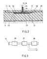
- the coil 14 provides the change over time in the Current conductor 5 flowing current proportional signals. These signals are arranged due to the suitability Shields 18 and 25 free from undesirable influences external fields and those occurring in the system transient processes. You will be in evaluation electronics 10 to a signal corresponding to the current to be determined integrated. As can be seen from Figure 3, these Signals first in an analog-to-digital converter 26 digitized and then the digitized signals in a trained as a digital integrator 27 Integrating device for a current to be measured corresponding signal integrated. This signal can then optionally in a downstream digital-to-analog converter 28 can be converted for an analog display and / or for further processing to other functional units of the system to get redirected.
Description
Bei der Erfindung wird ausgegangen von einem Stromwandler für eine Mittel- oder
Hochspannungsanlage nach dem Oberbegriff von Patentanspruch 1.The invention is based on a current transformer for a central or
High-voltage system according to the preamble of
Ein Stromwandler der vorgenannten Art ist in EP-A-0 165 835 beschrieben. Dieser Stromwandler weist einen aus unmagnetischem Material gebildeten torusförmigen Kern von rechteckigem Querschnitt auf, durch den ein stromführender Leiter einer Mittel- oder Hochspannungsanlage geführt ist, und welcher eine nach Art einer Rogowskispule gewickelte Spule trägt. Die Spule ist in einer Abschirmung gehalten. Ein aus einem Material hoher magnetischer Permeabilität bestehendes Teil der Abschirmung umgibt die Spule und schirmt sie nach aussen ab. Ein zwischen Spule und Stromleiter angeordnetes und aus unmagnetischem Material gebildetes Teil der Abschirmung schirmt die Spule gegenüber dem Stromleiter ab. Von den Spulenanschlüssen an eine Auswerteelektronik geführte Messignale zeichnen sich durch einen geringen Rauschpegel aus.A current transformer of the aforementioned type is described in EP-A-0 165 835. This Current transformer has a toroidal shape formed from non-magnetic material Core of rectangular cross-section through which a current-carrying conductor Medium or high voltage system is led, and which one like a Rogowski coil carries wound coil. The coil is in a shield held. A material made of a high magnetic permeability Part of the shield surrounds the coil and shields it from the outside. A arranged between coil and conductor and made of non-magnetic material formed part of the shield shields the coil from the conductor. Measurement signals led from the coil connections to an evaluation electronics are characterized by a low noise level.
Ein in FR-A-2 255 603 beschriebener Stromwandler für eine metallgekapselte Hochspannungsanlage enthält einen in der Metallkapselung angeordneten, ringförmig ausgebildeten Giessharzkörper, durch den ein stromführender Leiter der Anlage geführt ist, und in den drei axial gegeneinander versetzt angeordnete und vom Stromleiter durchsetzte Sekundärwicklungen eingebettet sind. Eine mittlere der drei Wicklungen ist auf einem eisenfreien, ringförmigen Kern mit rechteckigem Querschnitt angeordnet. Im Vergleich zum Radius und zur axialen Ausdehnung ist der Kern in radialer Richtung nur gering bemessen. Der Durchmesser der Metallkapselung kann so ersichtlich gering gehalten werden. Der Ausgang der mittleren Wicklung ist auf den Eingang eines von den beiden anderen Wicklungen gespeisten Operationsverstärkers einer Auswertelektronik geführt. Eine die Messgenauigkeit des Stromwandlers verbessernde Abschirmung der mittleren Wicklung weist dieser Stromwandler nicht auf.A current transformer described in FR-A-2 255 603 for a metal encapsulated High-voltage system contains one arranged in the metal encapsulation, ring-shaped cast resin body through which a current-carrying conductor the system is guided, and in the three axially offset and secondary windings penetrated by the current conductor are embedded. A middle of the three windings is on an iron-free, ring-shaped core with rectangular cross section. Compared to the radius and the axial The core is dimensioned only slightly in the radial direction. Of the The diameter of the metal encapsulation can obviously be kept small. The output of the middle winding is on the input of one of the two other windings fed operational amplifiers of evaluation electronics guided. A shield that improves the measuring accuracy of the current transformer this current transformer does not have the middle winding.
Bei einem aus FR-A-2 230 052 ersichtlichen Stromwandler für eine metallgekapselte Hochspannungsanlage sind in der Kapselung Sekundärwicklungen tragende, ringförmige Eisenkerne von rechteckigem Querschnitt angeordnet, welche auf einem ringförmig ausgebildeten Tragkörper aus Giessharz oder aus Metall gehalten sind. Im Vergleich zum Radius und zur axialen Ausdehnung sind die Kerne in radialer Richtung nur gering bemessen. Entsprechend dem zuvor beschriebenen Stromwandler kann der Durchmesser der Metallkapselung so gering gehalten werden.In the case of a current transformer for a metal-encapsulated current transformer as seen in FR-A-2 230 052 High-voltage systems are secondary windings in the encapsulation, annular iron cores of rectangular cross-section arranged on a ring-shaped support body made of cast resin or metal are held. In comparison to the radius and the axial extent, they are Cores dimensioned only slightly in the radial direction. According to the previous one described current transformer, the diameter of the metal encapsulation be kept low.
Aus IEE Proceedings, Bd.130, Nr.5, September 1983, Seiten 360-363 ist es bekannt, dass in mittel- oder hochspannungsführenden Leitern fliessende Ströme mit Hilfe von abgeschirmten Rogowskispulen potentialfrei mit guter Genauigkeit bestimmt werden können.From IEE Proceedings, Vol. 130, No. 5, September 1983, pages 360-363 it is known that currents flowing in medium or high voltage conductors with the help of shielded Rogowski coils potential-free with good accuracy can be determined.
Der Erfindung, wie sie in Patentanspruch 1 angegeben ist, liegt die Aufgabe
zugrunde, einen Stromwandler für Mittel- oder Hochspannungsanlagen
anzugeben, welcher geringe Abmessungen aufweist, und dessen Stromsensor
problemlos an beliebigen Stellen in die Anlage eingebaut werden kann und sich
dennoch durch eine besonders grosse Empfindlichkeit auszeichnet.The invention, as specified in
Der Stromwandler nach der Erfindung zeichnet sich bei geringem Gewicht und geringem Platzbedarf durch eine hohe Messgenauigkeit aus. Zudem weist er einen über viele Grössenordnungen erstreckten Messbereich auf sowie eine grosse Linearität in diesem Messbereich. Die guten Messeigenschaften sind zum einen eine Folge der geometrischen Gestaltung des Kerns seiner Rogowskispule, da hierdurch Unsymmetrien im Magnetfeld des zu messenden Stroms ausgeglichen werden und zugleich der Einfluss unerwünschter Fremdfelder verringert wird. Zum anderen wird durch die Verwendung von isotropem Material für den Kern der Rogowskispule und den die Spule fixierenden Isolierkörper erreicht, dass sich Kern und Isolierkörper bei Temperaturänderungen in allen Richtungen gleichmässig dehnen bzw. zusammenziehen. Die die Messgenauigkeit bestimmende Geometrie der Spule kann so durch ständige Temperaturüberwachung der Spule erfasst und eine aus dieser Überwachung resultierende ständige Anpassung der Auswerteelektronik leicht kompensiert werden.The current transformer according to the invention is lightweight and low space requirement due to high measuring accuracy. He also points a measuring range spanning many orders of magnitude and one great linearity in this measuring range. The good measuring properties are for a result of the geometric design of the core of his Rogowski coil, because this compensates for asymmetries in the magnetic field of the current to be measured and the influence of unwanted external fields is reduced. On the other hand, the use of isotropic material for the core of the Rogowski coil and the insulating body fixing the coil achieve that Core and insulating body evenly in the event of temperature changes in all directions stretch or contract. The one that determines the measuring accuracy Geometry of the coil can be controlled by constant temperature monitoring of the coil recorded and a constant adjustment of the resulting from this monitoring Evaluation electronics can be easily compensated.
Ein bevorzugtes Ausführungsbeispiel der Erfindung und die damit erzielbaren weiteren Vorteile werden nachfolgend anhand von Zeichnungen näher erläutert. A preferred embodiment of the invention and the achievable with it Further advantages are explained in more detail below with the aid of drawings.
In den Zeichnungen ist ein Ausführungsbeispiel der Erfindung vereinfacht dargestellt, und zwar zeigt:
- Fig.1
- eine Seitenansicht einer teilweise im Schnitt dargestellten metallgekapselten, gasisolierten Mittelspannungsschaltanlage mit einem Stromwandler nach der Erfindung,
- Fig.2
- eine Aufsicht auf einen im Schnitt dargestellten Teil des Stromwandlers nach Fig.1, und
- Fig.3
- ein den Signalablauf im Stromwandler nach den
Figuren 1 und 2 darstellendes Blockschaltbild.
- Fig. 1
- 2 shows a side view of a metal-encapsulated, gas-insulated medium-voltage switchgear assembly, partially shown in section, with a current transformer according to the invention,
- Fig. 2
- a plan view of a section of the current transformer shown in Figure 1, and
- Fig. 3
- a block diagram showing the signal flow in the current transformer according to Figures 1 and 2.
In Fig.1 ist eine metallgekapselte, gasisolierte
Mittelspannungsschaltanlage dargestellt,die mit Spannungen
bis zu 24 kV betrieben werden kann. Diese Anlage weist als
Metallkapselung ein geschnitten dargestelltes Gehäuse 1 auf.
Das Gehäuse ist mit einem Isoliergas, wie insbesondere SF6,
von bis zu einigen Bar Druck gefüllt. Im Inneren des Gehäuses
sind Starkstromkomponenten, wie Leistungsschalter 2,
Trennschalter 3 und Sammelschienen 4, angeordnet. Die
Starkstromkomponenten sind über Stromleiter 5 phasenweise
miteinander elektrisch verbunden. Über Kabeldurchführungen 6
werden die Stromleiter 5 aus dem Gehäuse 1 an Kabel 7
geführt. Die Grösse der in den Stromleitern 5 fliessenden
Ströme wird von Stromwandlern 8 erfasst. Jeder der
Stromwandler 8 weist einen den zugeordneten Stromleiter 5
konzentrisch umgebenden Stromsensor 9 auf sowie nicht
bezeichnete Signalleitungen und eine Auswerteelektronik 10,
in der die vom Stromsensor 9 erfassten und über die
Signalleitungen weitergeführten Messignale ausgewertet
werden.1 shows a metal-enclosed, gas-insulated medium-voltage switchgear that can be operated with voltages up to 24 kV. This system has a
Jeder Stromsensor 9 weist geringe Abmessungen auf und kann
daher problemlos an beliebigen Stellen in die Anlage
eingebaut werden. Zu bevorzugen ist eine Integration des
Stromsensors 9 in die Kabeldurchführung 6, da hierdurch deren
Abmessungen praktisch nicht beeinflusst werden, und da in
diesem Fall die Kabeldurchführung 6 zugleich als Tragkörper
des Stromsensors 9 wirkt und ein zusätzlicher Tragkörper
entbehrlich ist.Each
Aus Fig.2 sind Aufbau und Anordnung des Stromsensors 9 des
Stromwandlers 8 zu erkennen. Der in dieser Figur vergrössert
dargestellte Teil des Stromsensors 9 enthält im wesentlichen
einen ringförmigen, von der Kabeldurchführung 6 gebildeten
Tragkörper 13 sowie eine torusförmig gewickelte, ringförmige
Spule 14 und von der Spule 14 zur Auswertelektronik 10 des
Stromwandlers 8 geführte Signalleitungen 15 und 16, in
welcher Auswerteelektronik 10 aus den vom Stromsensor 9
abgegebenen Signalen Messwerte gebildet werden, die dem im
Stromleiter 5 fliessenden Strom entsprechen.The structure and arrangement of the
Der Tragkörper 13 enthält einen den Stromleiter 5 ringförmig
umgebenden Raum 17, in dem die Spule 14 angeordnet ist. Der
Raum 17 ist nahezu allseitig begrenzt von einer störende
elektrische Felder fernhaltenden Abschirmung 18 aus
elektrisch leitendem Material, wie insbesondere Aluminium
oder Kupfer. Die Abschirmung 18 steht über einen
Anschlusskontakt 19 mit dem Gehäuse 1 der Anlage in
elektrisch leitender Verbindung und ist so auf das definierte
Massepotential der Anlage gebracht. Hierdurch ist der Raum 17
elektrisch gegenüber dem Einfluss unerwünschter, etwa durch
transiente Vorgänge - wie Schalthandlungen oder
Blitzstösse - gebildeter Störfelder, abgeschirmt, und werden von der
Spule 14 daher beim Messen in der Anlage unter
Betriebsbedingungen nahezu fehlerfreie Signale abgegeben.The
Die Abschirmung 18 besteht im wesentlichen aus zwei
überwiegend hohlzylindrisch ausgebildeten Elektoden 20, 21,
von denen die Elektrode 20 zugleich eine Steuerelektode der
Kabeldurchführung 6 ist und die andere Elektrode 21
wulstartige Kontur aufweist. Beide Elektroden 20, 21 sind an
einer Stirnseite der Elektrode 21 miteinander elektrisch
leitend und mechanisch verbunden. An der anderen Stirnseite
der Elektrode 21 sind sie unter Bildung einer den Stromleiter
5 ringförmig umgebenden Isolierstelle 22 voneinander
elektrisch isoliert. Hierdurch wird der Raum 17 elektrisch
abgeschirmt und wird zugleich die Ausbildung unerwünschter
Wirbelströme vermieden.The
Die Spule 14 ist nach Art einer Rogowskispule auf einen
ringförmigen Kern 23 aus nichtferromagnetischem Material
gewickelt. Der Kern 23 hat in axialer Richtung geschnitten im
wesentlichen rechteckigen Querschnitt und ist im Vergleich zu
seinem Radius sowie zu seiner axialen Erstreckung in radialer
Richtung nur sehr gering bemessen. Bei einem Radius von
beispielsweise 55 mm und einer axialen Längserstreckung von
beispielsweise 30 mm weist er typischerweise eine Dicke von
nur 2 mm auf. Hierdurch werden Unsymmetrien im Magnetfeld des
zu messenden Stromes ausgeglichen und wird zugleich der
Einfluss unerwünschter Fremdfelder minimiert. Der die Spule
14 aufnehmende Raum 17 ist mit einem ringförmigen
Isolierkörper 24 ausgefüllt, durch den die Spule 14 im Raum
17 und damit auch am Tragkörper 13 fixiert ist.The
Der Isolierkörper 24 und der Kern 23 der Spule 14 enthalten
ein überwiegend isotropes Material. Hierdurch wird erreicht,
dass sich Isolierkörper 24 und Kern 23 bei
Temperaturänderungen in allen Richtungen gleichmässig dehnen
bzw. zusammenziehen. Die Geometrie der Spule 14 wird daher
bei Temperaturveränderungen linear verändert. Diese Änderung
kann durch eine ständige Temperaturüberwachung des
Stromsensors 10 und eine aus dieser Überwachung resultierende
ständige Anpassung der Auswerteelektronik 10 leicht
kompensiert werden.The insulating
Eine besonders hohe Messgenauigkeit lässt sich erreichen,
wenn das Material des Isolierkörpers 24 und des Kerns 23 der
Spule 14 einen an das Material des Tragkörpers 13 der
Kabeldurchführung 6 - üblicherweise eine ausgehärtete
Vergussmasse auf der Basis von Epoxidharz - bzw. der
Abschirmung 18 angepassten Koeffizienten der Wärmeausdehnung
aufweisen. Sehr bewährt als Material für den Isolierkörper 24
und/oder den Kern 23 hat sich eine mit Glaskügelchen gefüllte
Vergussmasse, insbesondere auf der Basis eines Epoxidharzes.
Als Material für den Kern 23 kann auch ein nichtferromagnetisches
Metall verwendet werden. Insbesondere
Aluminium ist hierfür besonders geeignet, da es bei hohen
Frequenzen induzierte Spannungsspitzen stark dämpft, und da
es zugleich einen dem im Isolierkörper 24 bzw. im Tragkörper
13 verwendeten Isoliermaterial entsprechenden Koeffizienten
der Wärmeausdehnung aufweist.A particularly high measuring accuracy can be achieved
if the material of the insulating
Der Stromsensor 10 lässt sich in einfacher Weise durch
Vergiessen vormontierter Teile, wie Abschirmung 18 mit
Anschlusskontakt 19, Stromleiter 5 und Spule 14 mit
Signalleitungen 15, 16 und einer die Signalleitungen
umgebenden und mit der Abschirmung 18 kontaktierten
Abschirmung 25 eines zur Auswerteelektronik geführten
abgeschirmten Messkabels, mit einer nach Aushärtung zum
Material des Isolierkörpers 24 sowie des Tragkörpers 13
führenden Vergussmasse fertigen. Soll der Stromsensor 9
unabhängig von der Kabeldurchführung 6 gefertigt werden, so
ist es möglich, die Spule 14 in einer Form unter Bildung des
Isolierkörpers 24 zu umgiessen und sodann die nach Aushärten
im Isolierkörper 24 fixierte Spule 14 in die mit
Montageansätzen versehene und nun zusätzlich als Tragkörper
dienende Abschirmung 18 einzusetzen oder die Spule 14 unter
Bildung des Isolierkörpers 24 direkt in der ebenfalls als
Tragkörper 13 ausgebildeten Abschirmung 18 zu umgiessen.The
Die Spule 14 liefert der zeitlichen Änderung des im
Stromleiter 5 fliessenden Stromes proportionale Signale.
Diese Signale sind aufgrund der geeignet angeordneten
Abschirmungen 18 und 25 frei von den Einflüssen unerwünschter
äusserer Fremdfelder und von in der Anlage auftretenden,
transienten Vorgängen. Sie werden in der Auswerteelektronik
10 zu einem dem zu ermittelndem Strom entsprechenden Signal
integriert. Wie aus Fig.3 ersichtlich ist, werden diese
Signale zunächst in einem Analog- Digital- Wandler 26
digitalisiert und die digitalisierten Signale anschliessend
in einer als Digitalintegrator 27 ausgebildeten
Integriervorrichtung zu einem dem zu messenden Strom
entsprechenden Signal integriert. Dieses Signal kann dann
wahlweise in einem nachgeschalteten Digital- Analog- Wandler
28 für eine Analoganzeige umgewandelt werden und/oder zur
weiteren Verarbeitung an andere Funktionseinheiten der Anlage
weitergeleitet werden. The
- 11
- Gehäusecasing
- 22nd
- LeistungsschalterCircuit breaker
- 33rd
- TrennschalterDisconnector
- 44th
- SammelschienenBusbars
- 55
- StromleiterConductor
- 66
- KabeldurchführungCable entry
- 77
- Kabelelectric wire
- 88th
- StromwandlerPower converter
- 99
- StromsensorCurrent sensor
- 1010th
- AuswerteelektronikEvaluation electronics
- 1313
- TragkörperSupporting body
- 1414
- SpuleKitchen sink
- 15, 1615, 16
- SignalleitungenSignal lines
- 1717th
- Raumroom
- 1818th
- Abschirmungshielding
- 1919th
- AnschlusskontaktConnection contact
- 20, 2120, 21
- ElektrodenElectrodes
- 2222
- IsolierstelleIsolation point
- 2323
- Kerncore
- 2424th
- IsolierkörperInsulating body
- 2525th
- Abschirmungshielding
- 2626
- Analog- Digital- WandlerAnalog to digital converter
- 2727
- DigitalintegratorDigital integrator
- 2828
- Digital- Analog- WandlerDigital to analog converter
Claims (9)
- Current transformer (8) for a medium- or high-voltage system having a current sensor (9) which is designed as a toroidally wound coil (14), an annular supporting body (13) which is used to hold the current sensor (9), an electrical conductor (5) which is concentrically surrounded by the coil (14), evaluation electronics (10) and a screened measurement cable which carries output signals from the coil (14) to the evaluation electronics, in the case of which the coil (14) is wound like a uniform-field coil onto an annular core (23) which is made of material that is not ferromagnetic and has an essentially rectangular cross-section in the axial direction, which coil (14) is arranged in a cavity (17) in the supporting body (13) which is screened from electrical fields and is designed with a hollow-cylindrical shape, characterized in that the annular core (23) has a small radial size in comparison with its radius and with its axial extent, in that the screened cavity (17) is filled with an insulating body (24) which fixes the coil (14), and in that the insulating body (24) and the core (23) of the coil (14) predominantly contain isotropic material.
- Current transformer according to Claim 1, characterized in that the material of the insulating body (24) and of the core (23) of the coil (14) have a coefficient of thermal expansion which is matched to that of the material of the supporting body (13).
- Current transformer according to one of Claims 1 or 2, characterized in that at least the core (23) is formed by a cured potting compound which is filled with spherical particles and is made of insulating material.
- Current transformer according to Claim 1, characterized in that the core (23) contains a metal which is not ferromagnetic.
- Current transformer according to Claim 4, characterized in that the metal which is not ferromagnetic is aluminium.
- Current transformer according to one of Claims 1 to 5, characterized in that the space (17) is surrounded by a screen (18) which is at the system earth potential and is electrically conductively connected to the screen (25) of the measurement cable.
- Current transformer according to Claim 6, characterized in that the screen (18) of the space (17) is interrupted by an isolation point (22) which surrounds the electrical conductor (5) in an annular shape.
- Current transformer according to one of Claims 6 or 7, characterized in that the screen (18) of the space (17) contains two electrodes (20, 21) which are designed to be predominantly hollow-cylindrical and one (20) of which is used as the control electrode of a cable bushing (6) of the system.
- Current transformer according to one of Claims 1 to 8, characterized in that the signals emitted from the coil (14) act in the evaluation electronics (10) on an integration apparatus which is designed as a digital integrator (27), is connected upstream of an analogue/digital converter (26) and is connected downstream of a digital/analogue converter (28).
Applications Claiming Priority (2)
| Application Number | Priority Date | Filing Date | Title |
|---|---|---|---|
| CH1196/91 | 1991-04-22 | ||
| CH119691 | 1991-04-22 |
Publications (3)
| Publication Number | Publication Date |
|---|---|
| EP0510426A2 EP0510426A2 (en) | 1992-10-28 |
| EP0510426A3 EP0510426A3 (en) | 1993-01-13 |
| EP0510426B1 true EP0510426B1 (en) | 1998-01-07 |
Family
ID=4204760
Family Applications (1)
| Application Number | Title | Priority Date | Filing Date |
|---|---|---|---|
| EP92106041A Expired - Lifetime EP0510426B1 (en) | 1991-04-22 | 1992-04-08 | Current transformer for medium or high tension |
Country Status (3)
| Country | Link |
|---|---|
| EP (1) | EP0510426B1 (en) |
| DE (2) | DE4122332A1 (en) |
| FI (1) | FI107304B (en) |
Cited By (1)
| Publication number | Priority date | Publication date | Assignee | Title |
|---|---|---|---|---|
| DE19939222A1 (en) * | 1999-08-18 | 2001-03-29 | Siemens Ag | Device and method for measuring network perturbations, in particular of railway vehicles |
Families Citing this family (9)
| Publication number | Priority date | Publication date | Assignee | Title |
|---|---|---|---|---|
| DE4315772A1 (en) * | 1993-05-07 | 1994-11-10 | Siemens Ag | Metal-enclosed high-voltage switchgear with a current transformer |
| DE4429959A1 (en) * | 1994-08-24 | 1996-02-29 | Abb Management Ag | Current transformer for a metal-encased gas-insulated high-voltage system |
| DE4435864C2 (en) * | 1994-10-07 | 1996-07-25 | Pfisterer Elektrotech Karl | Set in the form of a bushing or a socket for cable plugs |
| FI965298A (en) * | 1996-12-31 | 1998-07-01 | Abb Transmit Oy | Insulation |
| FI109153B (en) * | 1998-01-30 | 2002-05-31 | Abb Technology Ltd | Piece of insulation blank with a continuous primary current line |
| DE102004016602A1 (en) * | 2004-04-03 | 2005-10-20 | Abb Technology Ag Zuerich | Voltage/current-measurement system for measuring current on a switching installation has a conductor and a transformer linked to evaluatory electronics |
| DE102008034577B4 (en) * | 2008-07-24 | 2016-02-18 | Siemens Aktiengesellschaft | Current measuring arrangement |
| DE102010038894B4 (en) * | 2010-08-04 | 2014-12-24 | Siemens Aktiengesellschaft | Measuring system, circuit breaker and method |
| RU2603350C2 (en) * | 2011-08-05 | 2016-11-27 | Грин Сиз Венчурз, Элтиди | Feedthrough insulator |
Family Cites Families (7)
| Publication number | Priority date | Publication date | Assignee | Title |
|---|---|---|---|---|
| US3456222A (en) * | 1968-04-25 | 1969-07-15 | Gen Electric | High voltage current transformer |
| DE2325441C2 (en) * | 1973-05-17 | 1989-07-20 | Siemens AG, 1000 Berlin und 8000 München | Measuring transducer for installation in a metal capsule of a switchgear system |
| DE2363931C3 (en) * | 1973-12-20 | 1979-08-02 | Siemens Ag, 1000 Berlin Und 8000 Muenchen | Current measuring device |
| DE2939934C2 (en) * | 1979-09-28 | 1983-10-06 | Siemens Ag, 1000 Berlin Und 8000 Muenchen | Current transformer with a core shell |
| SU1101745A1 (en) * | 1983-04-06 | 1984-07-07 | Предприятие П/Я Г-4605 | Ac shunt |
| FR2564594B1 (en) * | 1984-05-21 | 1986-09-12 | Merlin Gerin | CURRENT SENSOR WITH AMAGNETIC CORE |
| CH667557A5 (en) * | 1985-03-14 | 1988-10-14 | Sprecher Energie Ag | HIGH VOLTAGE SWITCHGEAR. |
-
1991
- 1991-07-05 DE DE19914122332 patent/DE4122332A1/en not_active Withdrawn
-
1992
- 1992-04-08 DE DE59209094T patent/DE59209094D1/en not_active Expired - Fee Related
- 1992-04-08 EP EP92106041A patent/EP0510426B1/en not_active Expired - Lifetime
- 1992-04-16 FI FI921737A patent/FI107304B/en active
Cited By (1)
| Publication number | Priority date | Publication date | Assignee | Title |
|---|---|---|---|---|
| DE19939222A1 (en) * | 1999-08-18 | 2001-03-29 | Siemens Ag | Device and method for measuring network perturbations, in particular of railway vehicles |
Also Published As
| Publication number | Publication date |
|---|---|
| FI921737A (en) | 1992-10-23 |
| DE4122332A1 (en) | 1992-10-29 |
| EP0510426A2 (en) | 1992-10-28 |
| FI921737A0 (en) | 1992-04-16 |
| FI107304B (en) | 2001-06-29 |
| DE59209094D1 (en) | 1998-02-12 |
| EP0510426A3 (en) | 1993-01-13 |
Similar Documents
| Publication | Publication Date | Title |
|---|---|---|
| EP0522303B2 (en) | Combined voltage and current transducer for a metal-encapsulated gas-insulated high-voltage installation | |
| EP0510311B1 (en) | Current and voltage transformer for a metal encapsulated, gas insulated high-voltage installation | |
| EP0015905B1 (en) | Combined current and voltage transformers for a high voltage installation enclosed in a metal envelope filled with pressure gas | |
| EP0510426B1 (en) | Current transformer for medium or high tension | |
| DE102006061923A1 (en) | Rogowski sensor and method for measuring a current | |
| DE3544508A1 (en) | Combined transducer for measuring current and voltage simultaneously on pipe-sheathed conductors | |
| EP0510427B1 (en) | Voltage transformer for a medium or high voltage installation | |
| EP1569311B1 (en) | Compact current transformer housing for gas insulated switches | |
| DE4322944C2 (en) | Current transformer of an electrical switchgear filled with protective gas | |
| EP0889490A2 (en) | Current transformer for a metal-encapsulated gas-insulated high voltage installation | |
| DE4101858C1 (en) | ||
| DE60104788T2 (en) | Gas-insulated circuit breaker with integrated electronic current transformer | |
| DE3121398A1 (en) | Device for measuring high alternating voltages in high-voltage switching installations | |
| DE2363931C3 (en) | Current measuring device | |
| DE102019211950B3 (en) | Measuring an electrical voltage on a metal-enclosed switching device | |
| EP0768684B1 (en) | Current transformer with annular core to be built in a metal cast high-tension switchgear installation | |
| EP3864681B1 (en) | Current transformer module for a switchgear and corresponding switchgear | |
| DE4101859C1 (en) | ||
| DE966184C (en) | Current and voltage transformers with the same feed phase for high voltage systems in a spatially close assembly in one housing | |
| WO1999047936A1 (en) | Current sensor | |
| EP4007924B1 (en) | Measurement arrangement for measuring a voltage potential on a conductor in a power switching device and corresponding power switching device | |
| EP1014398B1 (en) | Current transformer in a gas insulated switchgear device | |
| EP3907839A1 (en) | A bushing for an air-insulated switchgear | |
| WO1993024942A1 (en) | Electrical high-voltage switchgear with at least one sensor | |
| DE8116028U1 (en) | Device for measuring high alternating voltages in high-voltage switchgear |
Legal Events
| Date | Code | Title | Description |
|---|---|---|---|
| PUAI | Public reference made under article 153(3) epc to a published international application that has entered the european phase |
Free format text: ORIGINAL CODE: 0009012 |
|
| AK | Designated contracting states |
Kind code of ref document: A2 Designated state(s): CH DE FR GB IT LI |
|
| PUAL | Search report despatched |
Free format text: ORIGINAL CODE: 0009013 |
|
| AK | Designated contracting states |
Kind code of ref document: A3 Designated state(s): CH DE FR GB IT LI |
|
| 17P | Request for examination filed |
Effective date: 19930625 |
|
| 17Q | First examination report despatched |
Effective date: 19960731 |
|
| GRAG | Despatch of communication of intention to grant |
Free format text: ORIGINAL CODE: EPIDOS AGRA |
|
| GRAG | Despatch of communication of intention to grant |
Free format text: ORIGINAL CODE: EPIDOS AGRA |
|
| GRAH | Despatch of communication of intention to grant a patent |
Free format text: ORIGINAL CODE: EPIDOS IGRA |
|
| GRAH | Despatch of communication of intention to grant a patent |
Free format text: ORIGINAL CODE: EPIDOS IGRA |
|
| GRAA | (expected) grant |
Free format text: ORIGINAL CODE: 0009210 |
|
| AK | Designated contracting states |
Kind code of ref document: B1 Designated state(s): CH DE FR GB IT LI |
|
| REG | Reference to a national code |
Ref country code: CH Ref legal event code: EP |
|
| REF | Corresponds to: |
Ref document number: 59209094 Country of ref document: DE Date of ref document: 19980212 |
|
| ITF | It: translation for a ep patent filed |
Owner name: DE DOMINICIS & MAYER S.R.L. |
|
| ET | Fr: translation filed | ||
| GBT | Gb: translation of ep patent filed (gb section 77(6)(a)/1977) |
Effective date: 19980312 |
|
| PLBE | No opposition filed within time limit |
Free format text: ORIGINAL CODE: 0009261 |
|
| STAA | Information on the status of an ep patent application or granted ep patent |
Free format text: STATUS: NO OPPOSITION FILED WITHIN TIME LIMIT |
|
| 26N | No opposition filed | ||
| REG | Reference to a national code |
Ref country code: GB Ref legal event code: IF02 |
|
| PGFP | Annual fee paid to national office [announced via postgrant information from national office to epo] |
Ref country code: CH Payment date: 20020319 Year of fee payment: 11 |
|
| PGFP | Annual fee paid to national office [announced via postgrant information from national office to epo] |
Ref country code: GB Payment date: 20020402 Year of fee payment: 11 |
|
| PGFP | Annual fee paid to national office [announced via postgrant information from national office to epo] |
Ref country code: FR Payment date: 20020416 Year of fee payment: 11 |
|
| PGFP | Annual fee paid to national office [announced via postgrant information from national office to epo] |
Ref country code: DE Payment date: 20020418 Year of fee payment: 11 |
|
| REG | Reference to a national code |
Ref country code: CH Ref legal event code: PFA Free format text: ASEA BROWN BOVERI AG TRANSFER- ABB SCHWEIZ HOLDING AG Ref country code: CH Ref legal event code: NV Representative=s name: ABB SCHWEIZ AG INTELLECTUAL PROPERTY (CH-LC/IP) |
|
| REG | Reference to a national code |
Ref country code: FR Ref legal event code: CD Ref country code: FR Ref legal event code: CA |
|
| PG25 | Lapsed in a contracting state [announced via postgrant information from national office to epo] |
Ref country code: GB Free format text: LAPSE BECAUSE OF NON-PAYMENT OF DUE FEES Effective date: 20030408 |
|
| PG25 | Lapsed in a contracting state [announced via postgrant information from national office to epo] |
Ref country code: LI Free format text: LAPSE BECAUSE OF NON-PAYMENT OF DUE FEES Effective date: 20030430 Ref country code: CH Free format text: LAPSE BECAUSE OF NON-PAYMENT OF DUE FEES Effective date: 20030430 |
|
| PG25 | Lapsed in a contracting state [announced via postgrant information from national office to epo] |
Ref country code: DE Free format text: LAPSE BECAUSE OF NON-PAYMENT OF DUE FEES Effective date: 20031101 |
|
| GBPC | Gb: european patent ceased through non-payment of renewal fee |
Effective date: 20030408 |
|
| REG | Reference to a national code |
Ref country code: CH Ref legal event code: PL |
|
| PG25 | Lapsed in a contracting state [announced via postgrant information from national office to epo] |
Ref country code: FR Free format text: LAPSE BECAUSE OF NON-PAYMENT OF DUE FEES Effective date: 20031231 |
|
| REG | Reference to a national code |
Ref country code: FR Ref legal event code: ST |
|
| PG25 | Lapsed in a contracting state [announced via postgrant information from national office to epo] |
Ref country code: IT Free format text: LAPSE BECAUSE OF NON-PAYMENT OF DUE FEES Effective date: 20050408 |