EP0510360A1 - Suction device to create a vacuum in containers - Google Patents
Suction device to create a vacuum in containers Download PDFInfo
- Publication number
- EP0510360A1 EP0510360A1 EP92104759A EP92104759A EP0510360A1 EP 0510360 A1 EP0510360 A1 EP 0510360A1 EP 92104759 A EP92104759 A EP 92104759A EP 92104759 A EP92104759 A EP 92104759A EP 0510360 A1 EP0510360 A1 EP 0510360A1
- Authority
- EP
- European Patent Office
- Prior art keywords
- axis
- suction device
- motor
- cylinder
- vacuum
- Prior art date
- Legal status (The legal status is an assumption and is not a legal conclusion. Google has not performed a legal analysis and makes no representation as to the accuracy of the status listed.)
- Granted
Links
Images


Classifications
-
- B—PERFORMING OPERATIONS; TRANSPORTING
- B65—CONVEYING; PACKING; STORING; HANDLING THIN OR FILAMENTARY MATERIAL
- B65B—MACHINES, APPARATUS OR DEVICES FOR, OR METHODS OF, PACKAGING ARTICLES OR MATERIALS; UNPACKING
- B65B31/00—Packaging articles or materials under special atmospheric or gaseous conditions; Adding propellants to aerosol containers
- B65B31/04—Evacuating, pressurising or gasifying filled containers or wrappers by means of nozzles through which air or other gas, e.g. an inert gas, is withdrawn or supplied
- B65B31/046—Evacuating, pressurising or gasifying filled containers or wrappers by means of nozzles through which air or other gas, e.g. an inert gas, is withdrawn or supplied the nozzles co-operating, or being combined, with a device for opening or closing the container or wrapper
- B65B31/047—Evacuating, pressurising or gasifying filled containers or wrappers by means of nozzles through which air or other gas, e.g. an inert gas, is withdrawn or supplied the nozzles co-operating, or being combined, with a device for opening or closing the container or wrapper the nozzles co-operating with a check valve in the opening of the container or wrapper
-
- F—MECHANICAL ENGINEERING; LIGHTING; HEATING; WEAPONS; BLASTING
- F04—POSITIVE - DISPLACEMENT MACHINES FOR LIQUIDS; PUMPS FOR LIQUIDS OR ELASTIC FLUIDS
- F04B—POSITIVE-DISPLACEMENT MACHINES FOR LIQUIDS; PUMPS
- F04B35/00—Piston pumps specially adapted for elastic fluids and characterised by the driving means to their working members, or by combination with, or adaptation to, specific driving engines or motors, not otherwise provided for
- F04B35/04—Piston pumps specially adapted for elastic fluids and characterised by the driving means to their working members, or by combination with, or adaptation to, specific driving engines or motors, not otherwise provided for the means being electric
Definitions
- the present invention refers to a suction device suitable to create a vacuum in containers, particularly for the preservation in a vacuum of food and of perishable materials in general.
- the "oxidization" of food can be prevented by preserving it in a vacuum.
- a device for domestic use is also known, being suitable to create a vacuum in containers and comprising a casing which houses an electric motor, a suction pump provided with a tip connected to a valve located on the container cover.
- This devices is provided with electronic means suitable to establish the vacuum degree inside the container by measuring the motor absorption power and comprising transmission devices in which a bevel gear pair is arranged to transmit motion from the motor to an eccentric actuating the pump.
- This device is illustrated in the Italian Patent Application MI91 A 000927 filed by the same applicant on April 03, 1991.
- the aim of the invention is to improve the previously illustrated devices, supplying a suction device that can be used with one hand only, that is capable of creating a high vacuum degree in the containers, as defined in independent claim 1.
- a reducer group is installed which is formed by a pinion force-fit onto the motor shaft and by a crown gear with an eccentric that actuates a connecting rod connected to the piston of the suction pump.
- the axis of the crown gear is perpendicular to the axis of the pinion, therefore motor and pump can be located on the same axis and the device substantially has a straight line shape.
- the pinion force-fit onto the motor shaft may be replaced by a worm, whose complanate axis is perfectly parallel to the pump axis.
- an interchangeable and elastic tip is provided that can perfectly fit the valve seating provided in the containers in which the vacuum must be created, said tip being housed in a transparent removable little cup collecting the eventual condensation during the use of the device.
- the device thus conceived can be used with one hand, putting the tip directly into the valve seating provided in the container and pushing with the thumb or the forefinger of the same hand a push-button switch conveniently located near the end of the device opposite to the tip.
- a set of leds of different colours can be installed, whose lighting is controlled by the absorption of the motor to signal, for instance, the functioning of the device and the reached degree of vacuum.
- a mechanical vacuum measuring device may be advantageously arranged and directly connected to the suction tip.
- the electric motor can be fed by the main electrical line by means of an electric cable with related plug, that comes out from the device.
- the device can work with low voltage supplied by a rechargeable battery incorporated therein.
- the device according to the invention may be used to blow in air, instead of suckering it, and this will not involve substantial changes in what has been previously illustrated and it may be easily accomplished by actuating the pump as a compressor.
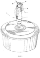
- the device according to the invention has been indicated as a whole with reference number 1 and it is shown in figure 1 applied on valve 3 of a container 2, in which a vacuum must be created.
- the suction device 1 comprises an outer casing formed by to substantially identical halves 4, 5, that are assembled with screws 6. Inside such casing, in the upper part, there is an electric motor 7, operated by a press switch 8, actuated by a pivoted key 9.
- a power cable 10 is partially shown, in case the motor 7 is fed by the line current. It is evident, however, that the device can be fed by a battery eventually rechargeable by the line current.
- three leds 11 of different colours are also shown whose status is determined by the absorption of the motor 7 and which serve to signal the degree of vacuum reached in the container during the functioning of the device.
- a support cage 13 is provided to hold the cylinder 14 of the pump and the reducer group, which will be described and which transmits the reciprocating motion to the piston 15.
- a conical pinion 17 is force-fit, that may be made integral with an impeller 18 for the cooling of the motor.
- the pinion 17 is engaged on a crown gear 19 rotatably mounted on a pivot 20 held by the cage 13.
- an hallow eccentric 37 is provided, which carries inside a lubricating tampon 21.
- a connecting rod 23 whose free end supports the piston 15.
- said free end has the shape of a sphere 40 located in semispheric seatings 41 of two symmetrical pads 42, opposed, to the piston.
- the pads 42 are fixed to a bush 43 inserted on them upon interposition of a gasket 44.
- the pivot 20, that is the axis of the crown gear 19, is perpendicular to the motor shaft 16, and the piston-cylinder unit of the suction pump is perfectly aligned with the axis of motor 7, therefore the device is substantially straight-lined.
- the axis of the cylinder 4 can be inclined, for instance up to 90° with respect to the motor shaft 16, on a plane perpendicular to the plane of the sheet in figure 3.
- valve body 24 upon interposition of a diaphragm valve 25.
- valve body 24 At the bottom of cylinder 14 there are two openings 26 and 27 connected, through the diaphragm valve 25, with a suction duct 28 and an exhaust duct 29 of the valve body 24, respectively.
- valve body 24, the diaphragm valve 25 and the cylinder 14 are assembled by means of a ring nut 30, threaded on a thread 31 made externally at the lower ends of two halves 4, 5 of the device casing.
- a terminal cap 32 is fixed, e.g. by means of a bayonet joint or by screwing, with a locking ring 31 interposed therebetween.
- This terminal cap preferably in transparent material, has an internal seat 33 for the press fit of a tip 34 in flexible material, such as rubber. This tip will engage the seating of valve 3 provided on the container 2.
- the tip 34 and the corresponding seating of valve 3 have the shape of a truncated piramid.
- the seat 33 of the terminal cap 32 has a solid end 35, as shown in the exploded view of figure 2, and side openings 36, through which the air sucked form container 2 is forced during the functioning of the device. In this way, the possible condensation is collected in the terminal cap 32 and drained by removing the cap from the device. The transaprency of the cap 32 allows a visual check of the accumulation of condensation in the cap.
- a mechanical indicator may be provided comprising a cylinder 45 whose lower end is connected, through a duct (not shown) obtained in the sidewall of the body valve 24, to the suction tip 34 and therefore, to the container 2, in which a vacuum is to be created.
- a piston 46 In the cylinder 45 a piston 46, with its gasket 47, is arranged and normally moved upwards by a spring 48.
- the vacuum obtained in the container 2 during the functioning of the device tends to move downwards the piston 46 , in opposition to the action of the spring 48, whose position, visible through the transparent cylinder 45 and through an opening 49 arranged in one of the two halves 4 and 5, signals the degree of vacuum created.
- the functioning of the suction device according to the invention is the following.
- the device is grabbed with one hand, as schematically indicated in figure 1 (or putting the hand of the opposite side in order to actuate the switch with the forefinger) and is located directly on a container 2 in which a vacuum must be created, by inserting the tip 34 in the seating of the corresponding valve 3 of the container. Pushing the pivoting key 9 the motor 7 is actuated, thus rotating the conical pinion 17 that transmits the rotation to the crown gear 19 which, through the eccentric 37, moves the connecting rod 23 - piston 15 group by alternate motion.
- the air sucked from the container passes through the openings 36, leaves the condensation and possible solid particles in the terminal cap 32 and enters the chamber of the cylinder passing through the duct 28 of the valve body 24, through the diaphragm valve 25 and through the opening 26 of the cylinder bottom.
- the opening 27 in the cylinder botton is obviously closed by the diaphragm valve 25.
- the diphragm valve 25 closes the opening 26 and opens the opening 27 of the cylinder bottom 14, thus sending to the exhaust the air present in the cylinder, through the duct 29 provided in the valve body 24.
- the degree of vacuum reached is signalled by the position of the piston 46, which moves as the vacuum in the container increases.
- the transmission system between motor and suction pump according to the invention is particularly advantageous when the above elements are perfectly aligned, but can be conveniently used up to an inclination of 45° of these elements.
- the device according to the invention can be used with any other type of containers, for instance flexible ones, provided that they have a valve suitable to seat the tip 34, which has a convenient square section but, being interchangeable, could be substituted with a tip having a different transverse section, e.g. a round one.
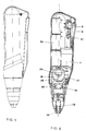
- FIG 5 and 6 a possible different embodiment of the invention is shown, wherein , in the place of pinion 17, a worm , still indicated with reference number 17, is located offset with respect to the rod 23, actuating a crown gear 19 having a suitable profile.
- 50 feeder batteries are provided, overlapped on a side of the device.
- 51 batteries a socket for the battery recharge or, in case, for the feeding by the line current is provided.
Landscapes
- Engineering & Computer Science (AREA)
- Mechanical Engineering (AREA)
- Chemical & Material Sciences (AREA)
- Dispersion Chemistry (AREA)
- General Engineering & Computer Science (AREA)
- Compressors, Vaccum Pumps And Other Relevant Systems (AREA)
- Supplying Of Containers To The Packaging Station (AREA)
- Manipulator (AREA)
- Vacuum Packaging (AREA)
- Making Paper Articles (AREA)
- External Artificial Organs (AREA)
- Auxiliary Devices For And Details Of Packaging Control (AREA)
Abstract
Description
- The present invention refers to a suction device suitable to create a vacuum in containers, particularly for the preservation in a vacuum of food and of perishable materials in general.
- It is well know that almost every type of food, either solid, semi-solid or liquid, tends to deteriorate rapidly when it is in contact with air, due to the aggression of air components, oxigen in particular.
- The "oxidization" of food can be prevented by preserving it in a vacuum.
- Although there are suction devices to create a vacuum in containers, this technique to preserve food is not very widespread, on the contrary it is absolutely unknown to most consumers, at domestic level, due to the drawbacks of the suction systems, that will be briefly illustrated.
- First of all, the known suction devices are very expensive, bulky and heavy, for this reason they must be fixed installations, at least during use. These equipments, in fact, are fixed to the wall or leaned on a flat surface and are connected to the valve of the container in which the vacuum must be created, by means of a flexible tube.
- As far as the internal structure of such equipments is concerned, they comprise an electric motor, on whose exit shaft an eccentric is mounted that directly actuates the piston of a suction pump whose shaft is perpendicular to the axis of the motor shaft. The position of the motor and of the pump plus the direct transmission between these elements require a high power, and therefore an over-dimensioning of the whole equipment.
- Although the problem of making the above equipments portable and handy, in order to increase their diffusion, is strongly felt, up to now that couldn't be realized, meanly due to the technical solutions adopted in the devices presently on the market.
- The applicant knows about a "portable" device consisting of a manual pump that presents the clear drawback of not reaching acceptable vacuum levels and of requiring the user to grip it with both hands.
- A device for domestic use is also known, being suitable to create a vacuum in containers and comprising a casing which houses an electric motor, a suction pump provided with a tip connected to a valve located on the container cover.
This devices is provided with electronic means suitable to establish the vacuum degree inside the container by measuring the motor absorption power and comprising transmission devices in which a bevel gear pair is arranged to transmit motion from the motor to an eccentric actuating the pump.
This device is illustrated in the Italian Patent Application MI91 A 000927 filed by the same applicant on April 03, 1991. - The aim of the invention is to improve the previously illustrated devices, supplying a suction device that can be used with one hand only, that is capable of creating a high vacuum degree in the containers, as defined in
independent claim 1. - In the suction device according to the invention, between the motor and the suction pump, a reducer group is installed which is formed by a pinion force-fit onto the motor shaft and by a crown gear with an eccentric that actuates a connecting rod connected to the piston of the suction pump.
- According to a particularly preferred embodiment of the invention, the axis of the crown gear is perpendicular to the axis of the pinion, therefore motor and pump can be located on the same axis and the device substantially has a straight line shape.
- According to a possible different embodiment, the pinion force-fit onto the motor shaft may be replaced by a worm, whose complanate axis is perfectly parallel to the pump axis.
- In the front part of the device an interchangeable and elastic tip is provided that can perfectly fit the valve seating provided in the containers in which the vacuum must be created, said tip being housed in a transparent removable little cup collecting the eventual condensation during the use of the device.
- The device thus conceived can be used with one hand, putting the tip directly into the valve seating provided in the container and pushing with the thumb or the forefinger of the same hand a push-button switch conveniently located near the end of the device opposite to the tip. On the housing of the device a set of leds of different colours can be installed, whose lighting is controlled by the absorption of the motor to signal, for instance, the functioning of the device and the reached degree of vacuum.
- In alternative or in addition, a mechanical vacuum measuring device may be advantageously arranged and directly connected to the suction tip.
- The electric motor can be fed by the main electrical line by means of an electric cable with related plug, that comes out from the device.
- According to an advantageous different embodiment, the device can work with low voltage supplied by a rechargeable battery incorporated therein.
- The device according to the invention may be used to blow in air, instead of suckering it, and this will not involve substantial changes in what has been previously illustrated and it may be easily accomplished by actuating the pump as a compressor.
- Further characteristics of the invention will be clear from the following detailed description, referring to a purely illustrative therefore in no ways limitative embodiment, illustrated in the attached drawings, in which:
- Figure 1 is an axonometric view showing the suction device according to the invention, during its use to create a vacuum in a container;
- Figure 2 is an exploded axonometric view of a preferred embodiment of the device of figure 1;
- Figure 3 is a mid-section taken from the device according to the invention;
- Figure 4 is a further section of the device;
- Figure 5 is a side-view of a possible modified embodiment of the shape of the device shown in the previous figures;
- Figure 6 is a mid-section of a different embodiment of the device according to the invention.
- With reference to figures 1 to 3, the device according to the invention has been indicated as a whole with
reference number 1 and it is shown in figure 1 applied on valve 3 of a container 2, in which a vacuum must be created. - As better shown in the exploded view of figure 2, the
suction device 1 comprises an outer casing formed by to substantiallyidentical halves screws 6. Inside such casing, in the upper part, there is anelectric motor 7, operated by apress switch 8, actuated by a pivotedkey 9. In these figures apower cable 10 is partially shown, in case themotor 7 is fed by the line current. It is evident, however, that the device can be fed by a battery eventually rechargeable by the line current. In the figures threeleds 11 of different colours are also shown whose status is determined by the absorption of themotor 7 and which serve to signal the degree of vacuum reached in the container during the functioning of the device. - Below motor 7 a
support cage 13 is provided to hold thecylinder 14 of the pump and the reducer group, which will be described and which transmits the reciprocating motion to thepiston 15. - On the outgoing end of the
shaft 16 of themotor 7, aconical pinion 17 is force-fit, that may be made integral with an impeller 18 for the cooling of the motor. Thepinion 17 is engaged on acrown gear 19 rotatably mounted on apivot 20 held by thecage 13. Inside thecrown gear 19 an hallow eccentric 37 is provided, which carries inside a lubricating tampon 21. Around the eccentric 37, there is the head of a connectingrod 23, whose free end supports thepiston 15. - In particular, said free end has the shape of a
sphere 40 located insemispheric seatings 41 of twosymmetrical pads 42, opposed, to the piston. Thepads 42 are fixed to abush 43 inserted on them upon interposition of agasket 44. - In the embodiment illustrated in figures 1 to 3, the
pivot 20, that is the axis of thecrown gear 19, is perpendicular to themotor shaft 16, and the piston-cylinder unit of the suction pump is perfectly aligned with the axis ofmotor 7, therefore the device is substantially straight-lined. However, it is evident that, keeping the position ofpivot 20, unchanged, the axis of thecylinder 4 can be inclined, for instance up to 90° with respect to themotor shaft 16, on a plane perpendicular to the plane of the sheet in figure 3. - Below
cylinder 14 there is avalve body 24, upon interposition of adiaphragm valve 25. At the bottom ofcylinder 14 there are twoopenings 26 and 27 connected, through thediaphragm valve 25, with asuction duct 28 and anexhaust duct 29 of thevalve body 24, respectively. - As shown is figure 3, the
valve body 24, thediaphragm valve 25 and the cylinder 14 (the latter might also be integral with cage 13) are assembled by means of aring nut 30, threaded on athread 31 made externally at the lower ends of twohalves - To the body valve 24 a
terminal cap 32 is fixed, e.g. by means of a bayonet joint or by screwing, with alocking ring 31 interposed therebetween. This terminal cap, preferably in transparent material, has aninternal seat 33 for the press fit of atip 34 in flexible material, such as rubber. This tip will engage the seating of valve 3 provided on the container 2. In the embodiment shown in the attached figures, thetip 34 and the corresponding seating of valve 3 have the shape of a truncated piramid. - The
seat 33 of theterminal cap 32 has asolid end 35, as shown in the exploded view of figure 2, andside openings 36, through which the air sucked form container 2 is forced during the functioning of the device. In this way, the possible condensation is collected in theterminal cap 32 and drained by removing the cap from the device. The transaprency of thecap 32 allows a visual check of the accumulation of condensation in the cap. - In alternative or in addition to the
leds 11 signalling the vacuum degree, a mechanical indicator may be provided comprising acylinder 45 whose lower end is connected, through a duct (not shown) obtained in the sidewall of thebody valve 24, to thesuction tip 34 and therefore, to the container 2, in which a vacuum is to be created. In the cylinder 45 apiston 46, with itsgasket 47, is arranged and normally moved upwards by aspring 48.
The vacuum obtained in the container 2 during the functioning of the device tends to move downwards thepiston 46 , in opposition to the action of thespring 48, whose position, visible through thetransparent cylinder 45 and through anopening 49 arranged in one of the twohalves - The functioning of the suction device according to the invention is the following.
- The device is grabbed with one hand, as schematically indicated in figure 1 (or putting the hand of the opposite side in order to actuate the switch with the forefinger) and is located directly on a container 2 in which a vacuum must be created, by inserting the
tip 34 in the seating of the corresponding valve 3 of the container. Pushing thepivoting key 9 themotor 7 is actuated, thus rotating theconical pinion 17 that transmits the rotation to thecrown gear 19 which, through the eccentric 37, moves the connecting rod 23 -piston 15 group by alternate motion. During the upward movement of the piston, that is the suction phase, the air sucked from the container passes through theopenings 36, leaves the condensation and possible solid particles in theterminal cap 32 and enters the chamber of the cylinder passing through theduct 28 of thevalve body 24, through thediaphragm valve 25 and through the opening 26 of the cylinder bottom. In this phase, the opening 27 in the cylinder botton is obviously closed by thediaphragm valve 25. During the downward movement of the piston, thediphragm valve 25 closes the opening 26 and opens theopening 27 of thecylinder bottom 14, thus sending to the exhaust the air present in the cylinder, through theduct 29 provided in thevalve body 24. - As the vacuum increases in container 2, the absorption of the
motor 7 increases, too and that is sensed by suitable electronic circuit and is signalled to the user by the selective lighting of theleds 11 indicating the degree of vacuum reached in the container. - In the case of a mechanical indicator, the degree of vacuum reached is signalled by the position of the
piston 46, which moves as the vacuum in the container increases. - The transmission system between motor and suction pump according to the invention is particularly advantageous when the above elements are perfectly aligned, but can be conveniently used up to an inclination of 45° of these elements.
- Even though in figure 1 a rigid container is shown, it is evident that the device according to the invention can be used with any other type of containers, for instance flexible ones, provided that they have a valve suitable to seat the
tip 34, which has a convenient square section but, being interchangeable, could be substituted with a tip having a different transverse section, e.g. a round one. - In figure 5 and 6 a possible different embodiment of the invention is shown, wherein , in the place of
pinion 17, a worm , still indicated withreference number 17, is located offset with respect to therod 23, actuating acrown gear 19 having a suitable profile. - According to this ambodiment, 50 feeder batteries are provided, overlapped on a side of the device. With 51 batteries, a socket for the battery recharge or, in case, for the feeding by the line current is provided.
- Without any substantial change, but simply by inverting the functioning of the
diaphragm valve 25, namely by actuating the pump as a compressor, it is possible to utilize the device according to the invention to blow in air, instead of sucking it. - Of course the invention is not limited to the embodiment described before and shown in the figures, but many modifications to its details can be carried out, which are within the reach of a technician in the art.
Claims (16)
- A suction device to create a vacuum in containers (2) provided with valve (3), comprising a casing which houses an electric motor (7) and a suction pump, formed by a cylinder-piston unit (14, 15) actuated by said electric motor, characterized in that a reducer group formed by a pinion (17) force-fit onto shaft (16) of motor (7) and by a crown gear (19) engaged with said pinion and carrying an eccentric (37) actuating a connecting rod (23) carrying the piston (15) is interposed between the notor and the suction pump, and in that at the end of the device, facing said piston, a hallow tip (34) is provided for the direct coupling of the device to the seating of the valve (3) of the container.
- Suction device according to claim 1, characterized in that the axis of said crown gear (19) is orthogonal to the axis of pinion (17), the axis of cylinder (4) coinciding with the axis of motor (7).
- Suction device according to claim 1, characterized in the axis of crown gear (19) is orthogonal to the axis of the pinion (17), ebing the axis of cylinder (4) inclined with respect to the axis of motor (7).
- Suction device according to claim 1, characterized in that the axis of crown gear (19) is inclined with respect to the perpendicular to the axis of pinion (17), so that the axis of cylinder (14) results to be inclined by the same angle with respect to the axis of the motor (7), being said angle preferably no more than 45°.
- Suction device according to claim 1, wherein pinion 17 is replaced by a worm engaging the crown gear 19, being the worm axis 17 complanate with respect to the cylinder axis 4.
- Suction device according to claim 5, characterized in that the worm axis 17 lies parallel to the cylinder axis 4.
- Suction device according to any one of the preceding claims, characterized in that the axis of the said crown gear (19) is formed by a pivot (20) supported by a cage (13) fixed to the motor (7).
- Suction device according to any one of the preceding claims, characterized in that the eccentric (37) has an internal cavity that houses a lubricating tampon (21) and is closed by a cap (22).
- Suction device according to any one of the preceding claims, characterized in that said piston 15 comprises two pads 42 mounted on a spheric end 40 of the rod 23 by means of a bush 43, upon interposition of a gasket 44.
- Suction device according to any of the preceding claims, characterized in that said casing is formed by two substantially equal halves (4, 5) forming, after being assembled, a thread (31) at one end, on which a ring nut (30) is screwed locking in position a valve body (24) and a diaphragm valve (25) at the bottom of the cylinder (14).
- Suction device according to any one of the preceding claims, characterized in that said tip (34) is interchangeable and is housed in a seat (33) of a terminal cap (32) that is conveniently transparent and serves as filter for the condensation and is removably fixed on the front of the valve body (24).
- Suction device according to any one of the previous claims, wherein said tip (34) has the shape of a truncated piramid.
- Suction device according to any one of the preceding claims, characterized in that a mechanical indicator of the vacuum degree reached in the container 2 is provided, comprising a chylinder 45, at least partially transparent, arranged adjacent to an opening 49 obtained in one of the two halves 4, 5, housing a piston 46, opposed to elastic means 48 and connected to the container 2 through said valve body 24.
- Suction device according to any one of the previous claims, characterized in that the two halves (4, 5) of the casing form in the assembly a window from which a pivoting key (9) stretches out acting on a switch (8) that operates the motor (7), as well as possible holes from which leds (11) stretch out, that signal the status of functioning of the device and the degree of vacuum created in the container (2) determined by the absorption of the motor (7).
- Suction device according to any one of the previous claims, characterized in that it is fed directly by the current line or by means of an enclosed battery 50 which is rechargeable.
- Suction device according to any onr of the previous claims, wherein said pump is actuated as a compressor and the device blows in air instead of sucking it.
Applications Claiming Priority (4)
| Application Number | Priority Date | Filing Date | Title |
|---|---|---|---|
| ITMI910927A IT1245859B (en) | 1991-04-03 | 1991-04-03 | Suction device for creating a vacuum in containers |
| ITMI910927 | 1991-04-03 | ||
| ITMI920129U | 1992-02-14 | ||
| IT000129 IT226247Z2 (en) | 1992-02-14 | 1992-02-14 | VACUUM DEVICE FOR VACUUM CREATION IN CONTAINERS |
Publications (2)
| Publication Number | Publication Date |
|---|---|
| EP0510360A1 true EP0510360A1 (en) | 1992-10-28 |
| EP0510360B1 EP0510360B1 (en) | 1995-06-14 |
Family
ID=26330699
Family Applications (1)
| Application Number | Title | Priority Date | Filing Date |
|---|---|---|---|
| EP92104759A Expired - Lifetime EP0510360B1 (en) | 1991-04-03 | 1992-03-19 | Suction device to create a vacuum in containers |
Country Status (9)
| Country | Link |
|---|---|
| US (1) | US5195427A (en) |
| EP (1) | EP0510360B1 (en) |
| AT (1) | ATE123733T1 (en) |
| CA (1) | CA2063776C (en) |
| DE (1) | DE69202912T2 (en) |
| DK (1) | DK0510360T3 (en) |
| ES (1) | ES2076591T3 (en) |
| GR (1) | GR3017154T3 (en) |
| HK (1) | HK196696A (en) |
Cited By (5)
| Publication number | Priority date | Publication date | Assignee | Title |
|---|---|---|---|---|
| WO1999003735A1 (en) * | 1997-07-17 | 1999-01-28 | Hubert Radermacher | Device for pressurizing a food receptacle which has been opened |
| EP1053945A1 (en) | 1999-05-21 | 2000-11-22 | Aracaria B.V. | A hand-held suction pump |
| WO2005044667A1 (en) * | 2003-10-16 | 2005-05-19 | Braun Gmbh | System for evacuating a food container, container comprising a lid, and method |
| FR2906753A1 (en) * | 2006-10-06 | 2008-04-11 | Jean Yves Delattre | Device for compacting empty containers before disposal, comprises controlled internal vacuum generation and suction system attached to collector to be sealed to container |
| EP4060195A1 (en) * | 2021-03-17 | 2022-09-21 | BSH Hausgeräte GmbH | Kitchen appliance, assembly and accessory therefor |
Families Citing this family (71)
| Publication number | Priority date | Publication date | Assignee | Title |
|---|---|---|---|---|
| DE4208656C2 (en) * | 1992-03-18 | 1995-07-20 | L & H Lemiteg Lebensmittel Und | Airtight lockable food storage container |
| US5394789A (en) * | 1993-07-08 | 1995-03-07 | Evans; John P. | Manually operable device for metering air through a valve system for drawing into, retaining and evacuating material from a chamber |
| US5485779A (en) * | 1993-07-08 | 1996-01-23 | Evans; John P. | Device for selectively pressurizing or evacuating a chamber with an oscillating air source by metering air through a valve system and a device for drawing into, retaining and evacuating material from a chamber |
| US5398811A (en) * | 1994-03-10 | 1995-03-21 | Latella, Jr.; Demetrio A. | Vacuum sealed canister |
| US5347918A (en) * | 1994-04-06 | 1994-09-20 | Chen Hung | Vacuum thermal cooker |
| US5765608A (en) * | 1995-11-08 | 1998-06-16 | Tilia International | Hand held vacuum device |
| US5806704A (en) * | 1996-08-02 | 1998-09-15 | Jamison; Richard W. | Paint container vacuum lid |
| US5806575A (en) * | 1997-04-11 | 1998-09-15 | Tsay; Shiu Chu | Vacuum extractor of a vacuum container |
| US5946919A (en) * | 1997-05-02 | 1999-09-07 | Sharper Image Corp. | Food conservator system |
| US5964255A (en) * | 1997-10-24 | 1999-10-12 | M. Kamenstein, Inc. | Vacuum sealed apparatus for storing foodstuffs |
| DE10010142C2 (en) * | 2000-03-03 | 2003-07-17 | Luk Fahrzeug Hydraulik | reciprocating engine |
| DE60103992T2 (en) * | 2000-03-31 | 2005-07-14 | Linak A/S | CONTROL DEVICE |
| US7328730B2 (en) * | 2000-12-08 | 2008-02-12 | Braun Gmbh | Food storage containers |
| DE10060998C1 (en) * | 2000-12-08 | 2001-10-31 | Braun Gmbh | Valve for food storage container has opening tab with suction aperture and smooth edging for sealing lip of suction connector of vacuum pump |
| US7096893B2 (en) * | 2000-12-08 | 2006-08-29 | Braun Gmbh | Food storage containers |
| DE10060996C1 (en) | 2000-12-08 | 2002-05-02 | Braun Gmbh | Apparatus, for evacuating foodstuff container with a closure valve, is an attachment for a conventional electrical kitchen appliance, to drive a vacuum vane pump |
| US7131550B2 (en) * | 2000-12-08 | 2006-11-07 | Braun Gmbh | Food storage containers |
| ITMI20010270A1 (en) * | 2001-02-09 | 2002-08-09 | Germano Maina | MACHINE FOR VACUUM PACKAGING IN PLASTIC BAGS AND RIGID CONTAINERS |
| US6626092B2 (en) * | 2002-01-22 | 2003-09-30 | Kenneth P. Tarlow | Vacuum producing appliance |
| US20030152673A1 (en) * | 2002-02-08 | 2003-08-14 | Kenneth Tarlow | Food preservation container |
| US6789690B2 (en) | 2002-04-19 | 2004-09-14 | Tilia International, Inc. | Hose direct canister lid |
| US6652251B1 (en) * | 2002-06-06 | 2003-11-25 | Jen-Fu Chen | Electric pump |
| US7048136B2 (en) * | 2002-11-05 | 2006-05-23 | Tilia International, Inc. | Canister lid with improved evacuation and vent assembly |
| US6994227B2 (en) * | 2003-02-11 | 2006-02-07 | Man-Hyun Kwon | vacuum container to preserve food |
| US6799697B1 (en) | 2003-02-24 | 2004-10-05 | Elbert G. Keller | Air injector apparatus |
| US7246555B2 (en) * | 2003-03-12 | 2007-07-24 | Shoot The Moon Products Ii, Llc | Portable vacuum food storage system |
| US20050061370A1 (en) * | 2003-08-16 | 2005-03-24 | Landen Higer | Vacuum packaging appliance spice rack |
| US7197860B2 (en) * | 2003-11-17 | 2007-04-03 | Vacnseal Holdings, Llc | Method and apparatus for vacuum sealing |
| US7614203B2 (en) * | 2004-01-13 | 2009-11-10 | Safety Solutions, Inc. | User installable vacuum seal apparatus for storage bags |
| US7325409B2 (en) | 2004-03-24 | 2008-02-05 | Espinosa Edward P | Vacuum storage apparatus with sliding drawers |
| US20060000733A1 (en) * | 2004-07-02 | 2006-01-05 | Albritton Charles W | Rigid container with vacuum channel walls |
| US7127875B2 (en) * | 2004-10-19 | 2006-10-31 | Intelli Innovations Ltd. | Portable vacuum device |
| KR200373368Y1 (en) * | 2004-10-20 | 2005-01-21 | (주)씨에스이 | Vacuum apparatus with hand-grip type for vessel |
| EP1686061A3 (en) * | 2005-01-28 | 2006-09-13 | Thomas Scholtis | Device for the vacuum packing of articles, containers for such a device and vacuum packing system |
| AU2006247093A1 (en) * | 2005-05-19 | 2006-11-23 | Steven Takayama | Compact apparatus for marinating and tenderizing meat |
| WO2006130384A2 (en) * | 2005-05-27 | 2006-12-07 | The Glad Products Company | Device and method for evacuating a storage bag |
| US7931052B2 (en) * | 2005-10-27 | 2011-04-26 | Schooley Bruce A | Vacuum storage container |
| US7874245B2 (en) * | 2005-12-16 | 2011-01-25 | John Spencer Kuzmier | Countertop fresh fruit and vegetable preservation device |
| US8240112B2 (en) * | 2006-05-31 | 2012-08-14 | The Glad Products Company | Evacuation device |
| US20080028730A1 (en) * | 2006-08-02 | 2008-02-07 | Savicki Alan F | Device and Method For Evacuating A Storage Bag |
| US20080085347A1 (en) * | 2006-10-06 | 2008-04-10 | Mah Pat Y | Vacuum marination device |
| US7677165B2 (en) * | 2006-11-15 | 2010-03-16 | Spencer Adams | Food storage device |
| EP1990541A2 (en) | 2007-05-11 | 2008-11-12 | Lock & Lock Co., Ltd. | Handheld vacuum suction device |
| KR100853752B1 (en) | 2007-05-11 | 2008-08-22 | 주식회사 락앤락 | Handy-held vacuum suction device |
| US7967509B2 (en) | 2007-06-15 | 2011-06-28 | S.C. Johnson & Son, Inc. | Pouch with a valve |
| US8096329B2 (en) * | 2007-06-15 | 2012-01-17 | S. C. Johnson & Son, Inc. | Hand-held vacuum pump |
| US9289094B2 (en) * | 2007-09-17 | 2016-03-22 | Accutemp Products, Inc. | Method and apparatus for filling a steam chamber |
| US8192182B2 (en) * | 2008-01-09 | 2012-06-05 | S.C. Johnson Home Storage, Inc. | Manual evacuation system |
| US8069987B2 (en) * | 2008-03-13 | 2011-12-06 | Anthony Choy | Vacuum activated shipping container |
| US8740591B2 (en) * | 2008-03-20 | 2014-06-03 | Reynolds Consumer Products LLC | Food storage bag vacuum pump |
| US8662334B2 (en) * | 2008-10-29 | 2014-03-04 | S.C. Johnson & Son, Inc. | Vacuum storage container with flexible diaphragm |
| KR101056628B1 (en) | 2009-03-27 | 2011-08-12 | (주)포에스텍 | Automatic Vacuum Suction |
| US20100301068A1 (en) * | 2009-06-02 | 2010-12-02 | Mark Henry Oliver King | Multipurpose camping container |
| US8967413B2 (en) | 2011-09-20 | 2015-03-03 | Scac Llc | Vacuum lid for use with baby food jars |
| US9302654B2 (en) * | 2013-01-25 | 2016-04-05 | Illinois Tool Works Inc. | Device for dispensing tire sealant |
| KR101479043B1 (en) | 2013-10-15 | 2015-01-05 | (주)포에스텍 | handy vacuumer |
| USD745153S1 (en) * | 2013-11-12 | 2015-12-08 | Riiviva LLC | Cellulite vacuum head |
| CN204624268U (en) * | 2015-04-22 | 2015-09-09 | 佛山市三水合成电器实业有限公司 | A kind of vacuum extractor self-styled without lock |
| EP4327841A3 (en) * | 2015-05-07 | 2024-05-22 | Avitus Orthopaedics, Inc. | Systems and methods for bone and tissue harvesting |
| JP6772618B2 (en) * | 2015-11-19 | 2020-10-21 | 株式会社デンソー | Electric air pump |
| US11104502B2 (en) | 2016-03-01 | 2021-08-31 | Jeffrey S. Melcher | Multi-function compact appliance and methods for a food or item in a container with a container storage technology |
| US10562690B2 (en) * | 2017-02-07 | 2020-02-18 | Sunbeam Products, Inc. | Valve assembly for a food storage container |
| CN108787554B (en) * | 2017-05-04 | 2024-01-05 | 苏州宝时得电动工具有限公司 | Hand-held high-pressure cleaning machine |
| US10003464B1 (en) | 2017-06-07 | 2018-06-19 | Cerebral, Incorporated | Biometric identification system and associated methods |
| US10266291B1 (en) * | 2017-10-21 | 2019-04-23 | Thomas Calvin Cannon, Jr. | Method and apparatus for vacuum packing food containers |
| TWI655366B (en) * | 2017-12-08 | 2019-04-01 | 緯和有限公司 | Portable air extracting device |
| US10747968B2 (en) | 2017-11-22 | 2020-08-18 | Jeffrey S. Melcher | Wireless device and selective user control and management of a wireless device and data |
| TWI696759B (en) * | 2019-07-25 | 2020-06-21 | 秦祖敬 | Air extracting device and method for calculating remaining time of extracting |
| US11602422B2 (en) * | 2020-04-17 | 2023-03-14 | Water Pik, Inc. | Chassis of an oral cleansing device |
| CA3229846A1 (en) * | 2021-08-23 | 2023-03-02 | Sunbeam Products, Inc | Handheld vacuum marinator device |
| CN115355153B (en) * | 2022-10-18 | 2023-01-31 | 宁波从越电子设备有限公司 | Vehicle-mounted inflator pump |
Citations (6)
| Publication number | Priority date | Publication date | Assignee | Title |
|---|---|---|---|---|
| US2465554A (en) * | 1946-10-21 | 1949-03-29 | Roy Maurice | Portable electric air pump |
| US2629539A (en) * | 1947-12-30 | 1953-02-24 | Payswell Products Corp | Motor-driven compressor unit |
| US4080105A (en) * | 1975-07-14 | 1978-03-21 | Connell Edwin E | Tire inflator |
| DE8610240U1 (en) * | 1986-04-15 | 1986-07-10 | Utility Electronics Industries Co. Ltd., Taipeh/T'ai-pei | Small compressor |
| US4712983A (en) * | 1985-11-08 | 1987-12-15 | Moynihan Patrick B | Air compressor accessory driven by portable electric drill |
| US4984611A (en) * | 1989-04-05 | 1991-01-15 | Zojirushi Corporation | Vacuum storage device |
Family Cites Families (14)
| Publication number | Priority date | Publication date | Assignee | Title |
|---|---|---|---|---|
| US303014A (en) * | 1884-08-05 | Air from preserving oases | ||
| DE567311C (en) * | 1932-12-31 | Mueller Otto | Preserving vessel with an air valve | |
| DE95335C (en) * | ||||
| US1621132A (en) * | 1925-01-02 | 1927-03-15 | Reinbold Frank | Method and apparatus for sealing fruit jars |
| US1572190A (en) * | 1925-02-05 | 1926-02-09 | Frank J Malthaner | Fruit preserver |
| US2049872A (en) * | 1934-09-29 | 1936-08-04 | Sera Shinichi | Vacuum pump |
| US2648474A (en) * | 1950-01-04 | 1953-08-11 | Crook Leslie George | Air extractor |
| US2669176A (en) * | 1951-06-22 | 1954-02-16 | Vernon B Lazerus | Air pump for food containers |
| IT1033739B (en) * | 1975-07-30 | 1979-08-10 | Saleri S | WATERPROOF CONTAINER FOR THE STORAGE OF VACUUM FOOD FOR DOMESTIC USE FITTED WITH MEANS FOR THE CREATION OF THE INTERNAL VACUUM |
| GB2066376B (en) * | 1977-11-09 | 1982-10-20 | Emerit Andre A C | Source of vacuum and device for creating and maintaining a negative pressure in an enclosure |
| US4362095A (en) * | 1981-03-02 | 1982-12-07 | Phyllis A. Wheatley | Storage container for ground coffee |
| US4615361A (en) * | 1985-01-11 | 1986-10-07 | Bartle Sr David C | Evacuating pump |
| EP0212201A1 (en) * | 1985-07-24 | 1987-03-04 | Ingko GmbH Industrieanlagenbau | Apparatus and method for the vacuum-filling of containers, in particular of flexible bags |
| ES2036786T3 (en) * | 1989-01-19 | 1993-06-01 | Bernardus Johannes Josephus Augustinus Schneider | CONTAINER. |
-
1992
- 1992-03-19 DE DE69202912T patent/DE69202912T2/en not_active Expired - Lifetime
- 1992-03-19 AT AT92104759T patent/ATE123733T1/en active
- 1992-03-19 EP EP92104759A patent/EP0510360B1/en not_active Expired - Lifetime
- 1992-03-19 ES ES92104759T patent/ES2076591T3/en not_active Expired - Lifetime
- 1992-03-19 DK DK92104759.3T patent/DK0510360T3/en active
- 1992-03-20 US US07/854,245 patent/US5195427A/en not_active Expired - Lifetime
- 1992-03-23 CA CA002063776A patent/CA2063776C/en not_active Expired - Lifetime
-
1995
- 1995-08-17 GR GR950402262T patent/GR3017154T3/en unknown
-
1996
- 1996-10-24 HK HK196696A patent/HK196696A/en not_active IP Right Cessation
Patent Citations (6)
| Publication number | Priority date | Publication date | Assignee | Title |
|---|---|---|---|---|
| US2465554A (en) * | 1946-10-21 | 1949-03-29 | Roy Maurice | Portable electric air pump |
| US2629539A (en) * | 1947-12-30 | 1953-02-24 | Payswell Products Corp | Motor-driven compressor unit |
| US4080105A (en) * | 1975-07-14 | 1978-03-21 | Connell Edwin E | Tire inflator |
| US4712983A (en) * | 1985-11-08 | 1987-12-15 | Moynihan Patrick B | Air compressor accessory driven by portable electric drill |
| DE8610240U1 (en) * | 1986-04-15 | 1986-07-10 | Utility Electronics Industries Co. Ltd., Taipeh/T'ai-pei | Small compressor |
| US4984611A (en) * | 1989-04-05 | 1991-01-15 | Zojirushi Corporation | Vacuum storage device |
Cited By (7)
| Publication number | Priority date | Publication date | Assignee | Title |
|---|---|---|---|---|
| WO1999003735A1 (en) * | 1997-07-17 | 1999-01-28 | Hubert Radermacher | Device for pressurizing a food receptacle which has been opened |
| EP1053945A1 (en) | 1999-05-21 | 2000-11-22 | Aracaria B.V. | A hand-held suction pump |
| WO2000071422A1 (en) | 1999-05-21 | 2000-11-30 | Aracaria B.V. | A hand-held suction pump |
| WO2005044667A1 (en) * | 2003-10-16 | 2005-05-19 | Braun Gmbh | System for evacuating a food container, container comprising a lid, and method |
| FR2906753A1 (en) * | 2006-10-06 | 2008-04-11 | Jean Yves Delattre | Device for compacting empty containers before disposal, comprises controlled internal vacuum generation and suction system attached to collector to be sealed to container |
| EP4060195A1 (en) * | 2021-03-17 | 2022-09-21 | BSH Hausgeräte GmbH | Kitchen appliance, assembly and accessory therefor |
| WO2022194548A1 (en) * | 2021-03-17 | 2022-09-22 | BSH Hausgeräte GmbH | Kitchen appliance, assembly and accessory therefor |
Also Published As
| Publication number | Publication date |
|---|---|
| DK0510360T3 (en) | 1995-10-30 |
| GR3017154T3 (en) | 1995-11-30 |
| ATE123733T1 (en) | 1995-06-15 |
| DE69202912D1 (en) | 1995-07-20 |
| CA2063776A1 (en) | 1992-10-04 |
| HK196696A (en) | 1996-11-01 |
| CA2063776C (en) | 2001-05-01 |
| EP0510360B1 (en) | 1995-06-14 |
| US5195427A (en) | 1993-03-23 |
| ES2076591T3 (en) | 1995-11-01 |
| DE69202912T2 (en) | 1995-11-02 |
Similar Documents
| Publication | Publication Date | Title |
|---|---|---|
| EP0510360A1 (en) | Suction device to create a vacuum in containers | |
| EP1053945B1 (en) | A hand-held suction pump | |
| EP0245876B1 (en) | Aspirator | |
| GB2199653A (en) | A multi function implement for illumination, ventilation or cleaning and pumping | |
| CA2899625C (en) | Battery operated backpack sprayer | |
| US5732470A (en) | Oscillating razor | |
| EP0401531A3 (en) | Battery powered vacuum cleaner | |
| US20080279702A1 (en) | Handheld vacuum suction device | |
| US3990523A (en) | Piston engine powered rotary drive with mount and fuel container | |
| US3308317A (en) | Portable electric hand tool with a moisture repellant cover | |
| JPH06317254A (en) | Suction device generating vacuum in container | |
| KR100991751B1 (en) | Handy type Vacuum Suction Apparatus having sealer | |
| CN211927391U (en) | Water intake device for water source quality detection | |
| TW474878B (en) | A hand-held suction pump | |
| EP0546496A2 (en) | Portable cutting apparatus | |
| CN220345018U (en) | Multifunctional muscle trainer | |
| CN217152337U (en) | Inflating pressure adjustable self-breaking air pump | |
| CN215598608U (en) | Elastic sheet contact type pressure transmitter | |
| CN114555942B (en) | Air compression device | |
| CN217055550U (en) | Oil leak detection device based on hydraulic pump | |
| EP1880946B1 (en) | Suction device for creating a vacuum inside containers, in particular food containers | |
| US2142620A (en) | Cut-out machine | |
| CN219107237U (en) | Sealing structure for water pump motor | |
| GB2211995A (en) | Tyre pressure detector | |
| CN211110796U (en) | Clothes hanger rope winding mechanism |
Legal Events
| Date | Code | Title | Description |
|---|---|---|---|
| PUAI | Public reference made under article 153(3) epc to a published international application that has entered the european phase |
Free format text: ORIGINAL CODE: 0009012 |
|
| AK | Designated contracting states |
Kind code of ref document: A1 Designated state(s): AT BE CH DE DK ES FR GB GR LI LU NL PT SE |
|
| 17P | Request for examination filed |
Effective date: 19921116 |
|
| 17Q | First examination report despatched |
Effective date: 19940308 |
|
| RIN1 | Information on inventor provided before grant (corrected) |
Inventor name: MAINA, GERMANO |
|
| GRAA | (expected) grant |
Free format text: ORIGINAL CODE: 0009210 |
|
| RAP1 | Party data changed (applicant data changed or rights of an application transferred) |
Owner name: JANKOVIC, MILAN |
|
| AK | Designated contracting states |
Kind code of ref document: B1 Designated state(s): AT BE CH DE DK ES FR GB GR LI LU NL PT SE |
|
| REF | Corresponds to: |
Ref document number: 123733 Country of ref document: AT Date of ref document: 19950615 Kind code of ref document: T |
|
| ET | Fr: translation filed | ||
| REF | Corresponds to: |
Ref document number: 69202912 Country of ref document: DE Date of ref document: 19950720 |
|
| SC4A | Pt: translation is available |
Free format text: 950614 AVAILABILITY OF NATIONAL TRANSLATION |
|
| REG | Reference to a national code |
Ref country code: DK Ref legal event code: T3 |
|
| REG | Reference to a national code |
Ref country code: GR Ref legal event code: FG4A Free format text: 3017154 |
|
| REG | Reference to a national code |
Ref country code: ES Ref legal event code: FG2A Ref document number: 2076591 Country of ref document: ES Kind code of ref document: T3 |
|
| REG | Reference to a national code |
Ref country code: FR Ref legal event code: CA |
|
| REG | Reference to a national code |
Ref country code: PT Ref legal event code: TE4A Free format text: MILAN JANKOVIC MC Effective date: 19951115 |
|
| PLBE | No opposition filed within time limit |
Free format text: ORIGINAL CODE: 0009261 |
|
| STAA | Information on the status of an ep patent application or granted ep patent |
Free format text: STATUS: NO OPPOSITION FILED WITHIN TIME LIMIT |
|
| 26N | No opposition filed | ||
| REG | Reference to a national code |
Ref country code: CH Ref legal event code: PUE Owner name: JANKOVIC, MILAN TRANSFER- ARACARIA B.V. |
|
| REG | Reference to a national code |
Ref country code: PT Ref legal event code: TE4A Free format text: MILAN JANKOVIC MC Effective date: 19970624 |
|
| REG | Reference to a national code |
Ref country code: GB Ref legal event code: 732E |
|
| REG | Reference to a national code |
Ref country code: FR Ref legal event code: CA |
|
| REG | Reference to a national code |
Ref country code: FR Ref legal event code: TP |
|
| NLS | Nl: assignments of ep-patents |
Owner name: ARACARIA B.V. |
|
| REG | Reference to a national code |
Ref country code: PT Ref legal event code: PC4A Free format text: ARACARIA B.V. NL Effective date: 20001123 |
|
| PGFP | Annual fee paid to national office [announced via postgrant information from national office to epo] |
Ref country code: PT Payment date: 20010315 Year of fee payment: 10 |
|
| PGFP | Annual fee paid to national office [announced via postgrant information from national office to epo] |
Ref country code: LU Payment date: 20010327 Year of fee payment: 10 |
|
| REG | Reference to a national code |
Ref country code: GB Ref legal event code: IF02 |
|
| PG25 | Lapsed in a contracting state [announced via postgrant information from national office to epo] |
Ref country code: LU Free format text: LAPSE BECAUSE OF NON-PAYMENT OF DUE FEES Effective date: 20020319 |
|
| PG25 | Lapsed in a contracting state [announced via postgrant information from national office to epo] |
Ref country code: PT Free format text: LAPSE BECAUSE OF NON-PAYMENT OF DUE FEES Effective date: 20020930 |
|
| REG | Reference to a national code |
Ref country code: PT Ref legal event code: MM4A Free format text: LAPSE DUE TO NON-PAYMENT OF FEES Effective date: 20020930 |
|
| REG | Reference to a national code |
Ref country code: CH Ref legal event code: PCAR Free format text: ISLER & PEDRAZZINI AG;POSTFACH 1772;8027 ZUERICH (CH) |
|
| PGFP | Annual fee paid to national office [announced via postgrant information from national office to epo] |
Ref country code: SE Payment date: 20091222 Year of fee payment: 19 |
|
| PGFP | Annual fee paid to national office [announced via postgrant information from national office to epo] |
Ref country code: ES Payment date: 20100324 Year of fee payment: 19 |
|
| PGFP | Annual fee paid to national office [announced via postgrant information from national office to epo] |
Ref country code: GR Payment date: 20100323 Year of fee payment: 19 |
|
| PGFP | Annual fee paid to national office [announced via postgrant information from national office to epo] |
Ref country code: DK Payment date: 20110328 Year of fee payment: 20 |
|
| PGFP | Annual fee paid to national office [announced via postgrant information from national office to epo] |
Ref country code: NL Payment date: 20110328 Year of fee payment: 20 Ref country code: CH Payment date: 20110328 Year of fee payment: 20 Ref country code: FR Payment date: 20110401 Year of fee payment: 20 Ref country code: AT Payment date: 20110323 Year of fee payment: 20 |
|
| PGFP | Annual fee paid to national office [announced via postgrant information from national office to epo] |
Ref country code: DE Payment date: 20110331 Year of fee payment: 20 Ref country code: BE Payment date: 20110328 Year of fee payment: 20 Ref country code: GB Payment date: 20110324 Year of fee payment: 20 |
|
| REG | Reference to a national code |
Ref country code: SE Ref legal event code: EUG |
|
| PG25 | Lapsed in a contracting state [announced via postgrant information from national office to epo] |
Ref country code: GR Free format text: LAPSE BECAUSE OF NON-PAYMENT OF DUE FEES Effective date: 20111004 |
|
| REG | Reference to a national code |
Ref country code: DE Ref legal event code: R071 Ref document number: 69202912 Country of ref document: DE |
|
| REG | Reference to a national code |
Ref country code: DE Ref legal event code: R071 Ref document number: 69202912 Country of ref document: DE |
|
| REG | Reference to a national code |
Ref country code: NL Ref legal event code: V4 Effective date: 20120319 |
|
| REG | Reference to a national code |
Ref country code: CH Ref legal event code: PL |
|
| BE20 | Be: patent expired |
Owner name: *ARACARIA B.V. Effective date: 20120319 |
|
| REG | Reference to a national code |
Ref country code: DK Ref legal event code: EUP |
|
| REG | Reference to a national code |
Ref country code: GB Ref legal event code: PE20 Expiry date: 20120318 |
|
| REG | Reference to a national code |
Ref country code: ES Ref legal event code: FD2A Effective date: 20120423 |
|
| PG25 | Lapsed in a contracting state [announced via postgrant information from national office to epo] |
Ref country code: DE Free format text: LAPSE BECAUSE OF EXPIRATION OF PROTECTION Effective date: 20120320 |
|
| PG25 | Lapsed in a contracting state [announced via postgrant information from national office to epo] |
Ref country code: GB Free format text: LAPSE BECAUSE OF EXPIRATION OF PROTECTION Effective date: 20120318 |
|
| PG25 | Lapsed in a contracting state [announced via postgrant information from national office to epo] |
Ref country code: ES Free format text: LAPSE BECAUSE OF NON-PAYMENT OF DUE FEES Effective date: 20110320 |
|
| REG | Reference to a national code |
Ref country code: AT Ref legal event code: MK07 Ref document number: 123733 Country of ref document: AT Kind code of ref document: T Effective date: 20120319 |
|
| PG25 | Lapsed in a contracting state [announced via postgrant information from national office to epo] |
Ref country code: SE Free format text: LAPSE BECAUSE OF NON-PAYMENT OF DUE FEES Effective date: 20110320 |