EP0510328A2 - Apparatus for treating activated sludge - Google Patents
Apparatus for treating activated sludge Download PDFInfo
- Publication number
- EP0510328A2 EP0510328A2 EP92103240A EP92103240A EP0510328A2 EP 0510328 A2 EP0510328 A2 EP 0510328A2 EP 92103240 A EP92103240 A EP 92103240A EP 92103240 A EP92103240 A EP 92103240A EP 0510328 A2 EP0510328 A2 EP 0510328A2
- Authority
- EP
- European Patent Office
- Prior art keywords
- filter membrane
- membrane modules
- activated sludge
- treating apparatus
- water
- Prior art date
- Legal status (The legal status is an assumption and is not a legal conclusion. Google has not performed a legal analysis and makes no representation as to the accuracy of the status listed.)
- Granted
Links
- 239000010802 sludge Substances 0.000 title claims abstract description 30
- 239000012528 membrane Substances 0.000 claims abstract description 128
- XLYOFNOQVPJJNP-UHFFFAOYSA-N water Substances O XLYOFNOQVPJJNP-UHFFFAOYSA-N 0.000 claims abstract description 44
- 239000007788 liquid Substances 0.000 claims abstract description 6
- 239000007787 solid Substances 0.000 claims abstract description 5
- 238000007664 blowing Methods 0.000 claims description 21
- 238000004140 cleaning Methods 0.000 claims description 16
- 239000000725 suspension Substances 0.000 claims description 7
- 238000000034 method Methods 0.000 claims description 3
- 238000005406 washing Methods 0.000 claims description 2
- 239000002351 wastewater Substances 0.000 abstract description 7
- 239000010865 sewage Substances 0.000 abstract description 4
- 239000010797 grey water Substances 0.000 abstract description 3
- 238000013019 agitation Methods 0.000 description 11
- 230000000694 effects Effects 0.000 description 9
- 238000005273 aeration Methods 0.000 description 7
- 239000007789 gas Substances 0.000 description 4
- 238000004581 coalescence Methods 0.000 description 3
- 230000003247 decreasing effect Effects 0.000 description 3
- 238000000151 deposition Methods 0.000 description 3
- 239000007791 liquid phase Substances 0.000 description 3
- QGZKDVFQNNGYKY-UHFFFAOYSA-N Ammonia Chemical compound N QGZKDVFQNNGYKY-UHFFFAOYSA-N 0.000 description 2
- QVGXLLKOCUKJST-UHFFFAOYSA-N atomic oxygen Chemical compound [O] QVGXLLKOCUKJST-UHFFFAOYSA-N 0.000 description 2
- 238000010276 construction Methods 0.000 description 2
- 230000008021 deposition Effects 0.000 description 2
- 230000004907 flux Effects 0.000 description 2
- 238000012423 maintenance Methods 0.000 description 2
- 239000001301 oxygen Substances 0.000 description 2
- 229910052760 oxygen Inorganic materials 0.000 description 2
- 229910021529 ammonia Inorganic materials 0.000 description 1
- 230000015556 catabolic process Effects 0.000 description 1
- 238000004891 communication Methods 0.000 description 1
- 238000006731 degradation reaction Methods 0.000 description 1
- 238000013461 design Methods 0.000 description 1
- 238000011161 development Methods 0.000 description 1
- 239000006185 dispersion Substances 0.000 description 1
- 238000004090 dissolution Methods 0.000 description 1
- 239000012530 fluid Substances 0.000 description 1
- 239000012071 phase Substances 0.000 description 1
- 238000000926 separation method Methods 0.000 description 1
- 238000010008 shearing Methods 0.000 description 1
- 239000000126 substance Substances 0.000 description 1
Images




Classifications
-
- B—PERFORMING OPERATIONS; TRANSPORTING
- B01—PHYSICAL OR CHEMICAL PROCESSES OR APPARATUS IN GENERAL
- B01D—SEPARATION
- B01D65/00—Accessories or auxiliary operations, in general, for separation processes or apparatus using semi-permeable membranes
- B01D65/08—Prevention of membrane fouling or of concentration polarisation
-
- B—PERFORMING OPERATIONS; TRANSPORTING
- B01—PHYSICAL OR CHEMICAL PROCESSES OR APPARATUS IN GENERAL
- B01D—SEPARATION
- B01D61/00—Processes of separation using semi-permeable membranes, e.g. dialysis, osmosis or ultrafiltration; Apparatus, accessories or auxiliary operations specially adapted therefor
- B01D61/14—Ultrafiltration; Microfiltration
-
- B—PERFORMING OPERATIONS; TRANSPORTING
- B01—PHYSICAL OR CHEMICAL PROCESSES OR APPARATUS IN GENERAL
- B01D—SEPARATION
- B01D61/00—Processes of separation using semi-permeable membranes, e.g. dialysis, osmosis or ultrafiltration; Apparatus, accessories or auxiliary operations specially adapted therefor
- B01D61/14—Ultrafiltration; Microfiltration
- B01D61/18—Apparatus therefor
-
- B—PERFORMING OPERATIONS; TRANSPORTING
- B01—PHYSICAL OR CHEMICAL PROCESSES OR APPARATUS IN GENERAL
- B01D—SEPARATION
- B01D65/00—Accessories or auxiliary operations, in general, for separation processes or apparatus using semi-permeable membranes
-
- B—PERFORMING OPERATIONS; TRANSPORTING
- B01—PHYSICAL OR CHEMICAL PROCESSES OR APPARATUS IN GENERAL
- B01D—SEPARATION
- B01D65/00—Accessories or auxiliary operations, in general, for separation processes or apparatus using semi-permeable membranes
- B01D65/02—Membrane cleaning or sterilisation ; Membrane regeneration
-
- C—CHEMISTRY; METALLURGY
- C02—TREATMENT OF WATER, WASTE WATER, SEWAGE, OR SLUDGE
- C02F—TREATMENT OF WATER, WASTE WATER, SEWAGE, OR SLUDGE
- C02F3/00—Biological treatment of water, waste water, or sewage
- C02F3/02—Aerobic processes
-
- C—CHEMISTRY; METALLURGY
- C02—TREATMENT OF WATER, WASTE WATER, SEWAGE, OR SLUDGE
- C02F—TREATMENT OF WATER, WASTE WATER, SEWAGE, OR SLUDGE
- C02F3/00—Biological treatment of water, waste water, or sewage
- C02F3/02—Aerobic processes
- C02F3/12—Activated sludge processes
-
- C—CHEMISTRY; METALLURGY
- C02—TREATMENT OF WATER, WASTE WATER, SEWAGE, OR SLUDGE
- C02F—TREATMENT OF WATER, WASTE WATER, SEWAGE, OR SLUDGE
- C02F3/00—Biological treatment of water, waste water, or sewage
- C02F3/02—Aerobic processes
- C02F3/12—Activated sludge processes
- C02F3/1236—Particular type of activated sludge installations
- C02F3/1268—Membrane bioreactor systems
- C02F3/1273—Submerged membrane bioreactors
-
- B—PERFORMING OPERATIONS; TRANSPORTING
- B01—PHYSICAL OR CHEMICAL PROCESSES OR APPARATUS IN GENERAL
- B01D—SEPARATION
- B01D2321/00—Details relating to membrane cleaning, regeneration, sterilization or to the prevention of fouling
- B01D2321/18—Use of gases
- B01D2321/185—Aeration
-
- B—PERFORMING OPERATIONS; TRANSPORTING
- B01—PHYSICAL OR CHEMICAL PROCESSES OR APPARATUS IN GENERAL
- B01D—SEPARATION
- B01D2321/00—Details relating to membrane cleaning, regeneration, sterilization or to the prevention of fouling
- B01D2321/30—Mechanical cleaning, e.g. with brushes or scrapers
-
- C—CHEMISTRY; METALLURGY
- C02—TREATMENT OF WATER, WASTE WATER, SEWAGE, OR SLUDGE
- C02F—TREATMENT OF WATER, WASTE WATER, SEWAGE, OR SLUDGE
- C02F2103/00—Nature of the water, waste water, sewage or sludge to be treated
- C02F2103/002—Grey water, e.g. from clothes washers, showers or dishwashers
-
- Y—GENERAL TAGGING OF NEW TECHNOLOGICAL DEVELOPMENTS; GENERAL TAGGING OF CROSS-SECTIONAL TECHNOLOGIES SPANNING OVER SEVERAL SECTIONS OF THE IPC; TECHNICAL SUBJECTS COVERED BY FORMER USPC CROSS-REFERENCE ART COLLECTIONS [XRACs] AND DIGESTS
- Y02—TECHNOLOGIES OR APPLICATIONS FOR MITIGATION OR ADAPTATION AGAINST CLIMATE CHANGE
- Y02W—CLIMATE CHANGE MITIGATION TECHNOLOGIES RELATED TO WASTEWATER TREATMENT OR WASTE MANAGEMENT
- Y02W10/00—Technologies for wastewater treatment
- Y02W10/10—Biological treatment of water, waste water, or sewage
Definitions
- the present invention relates to an activated sludge treating apparatus for use in treating wastewater, such as gray water and sewage.
- a plurality of filter membrane modules are vertically arranged in parallel spaced relation within a treating tank, whereby the water to be treated is separated into solid and liquid by being passed through the filter membrane modules so that water that has passed through the filter membrane modules is extracted as treated water.
- a diffused aeration pipe having a plurality of jet holes is disposed at a level below the filter membrane modules in order to prevent deposition and growth of cake and gel layers on the outer surfaces of the filter membrane modules.
- the air lift action of air blow from the diffused aeration pipe serves to create upward flowing agitation currents of both gas and liquid phases which are utilized to clean the membrane surfaces of the filter membrane modules.
- Another problem is that when the rate of air blow exceeds a specific value, for example, about 1 (m3 / m3 ⁇ min., where denominator m3 represents cross-sectional area of flow path of gas -liquid phase currents), the air lift action of air blow is decreased due to air-bubble coalescence, which results in decreased energy efficiency.
- a further problem is that the distance between the diffused aeration pipe and the lower end of the filter membrane modules is so short that air blown from the diffused aeration pipe is unlikely to be uniformly dispersed, which fact will not only tend to decrease the air lift effect of air blow but may tend to create some dead space in filter membrane modules which will remain isolated from gas -liquid phase current flow. As a consequence, cake layers or the like will deposit and grow on such portion of filter membrane modules, thus lowering the flux of the filter membrane modules.
- the present invention is directed to overcoming the foregoing problems, and accordingly it is a primary object of the invention to provide a membrane-separation type activated sludge treating apparatus which eliminates the possibility of any dead space being created in filter membrane modules, is well adapted for uniform cleaning of the entire membrane surfaces of filter membrane modules such that cake layers or the like can be positively prevented from depositing and growing on the membrane surfaces, and which involves less power requirement.
- an activated sludge treating apparatus comprising: a treating tank in which water to be treated is stored; a plurality of filter membrane modules vertically arranged in spaced relation within the treating tank for separating said water to be treated into solid and liquid by passing the water therethrough, thereby to extract treated water; and means disposed at a level below said filter membrane modules for agitating said water to be treated.
- the entire membrane surface of each filter membrane module can be uniformly and positively cleaned by agitation currents created by the agitating means. Therefore, even when the magnitude of air blow from an air blowing pipe or the like is to be adjusted according to the B O D concentration of the water to be treated, the entire membrane surface of each filter membrane module can be uniformly and positively cleaned without being influenced by the rate and velocity of air blow.
- FIG. 1 illustrates the first embodiment of the invention.
- a plurality of filter units 2 are arranged in a treating tank 1.
- Each filter unit 2 includes a cylindrical casing 3 which is open at its top and bottom portions, and a plurality of filter membrane modules 4 of plate-like shape which are vertically arranged in equispaced relation within the casing 3.
- the casing 3 is of a vertically splitable, two-part construction such that it has first and second casing members 3a, 3b.
- Filter membrane modules 4 are arranged in the first casing member 3a, and a smaller casing member 3c of cylindrical configuration is provided in the second casing member 3b.
- Each filter membrane module 4 is removably disposed in first casing member 3a so that it may be drawn upward for removal. Therefore, filter membrane modules in may be removed upward one by one for being individually cleaned and/or replaced. It is possible to separate first casing member 3a or the upper casing member from second casing member 3b or the lower casing member, thereby to remove the first casing member 3a from the treating tank 1 with the plurality of filter membrane modules 4 as attached to the first casing member 3b, so that the filter membrane modules 4 may be individually cleaned and/or replaced.
- Each filter membrane module 4 is connected at its upper end via a branch pipe 6a to a suction pipe 6 which is fitted with a suction pump 5 at a suitable location.
- a wastewater supply pipe 7 for feeding wastewater into the treating tank 1 is open at a location above the treating tank 1.
- An agitating element 9 having a drive motor 8 is disposed within the smaller casing 3c which is positioned below the filter membrane modules 4.
- an air-blowing pipe 10 which extends from the top side of the tank 1 to the bottom side of the tank 1; and a blower 11 is disposed on the proximal end side of the air blowing pipe 10 at a location outside the tank 1.
- wastewater such as gray water and sewage
- wastewater supply pipe 7 which is introduced from the wastewater supply pipe 7 into the treating tank 1
- activated sludge present in the tank 1 for being treated therein.
- the water being treated is exposed to air blown by the blower 11 through a plurality of orifices at the tip of the air blowing pipe 10 and is digested by activated sludge.
- the water being treated is sucked by the suction pump 5 through filter membrane modules 4 and the suction pipe 6, being separated into solid and liquid as it passes through the filter membrane modules 4, and that part of the water which has passed through the filter membrane modules 4 is extracted as treated water.
- Agitation currents created by the agitating element 9 are allowed to flow upward between adjacent filter membrane modules 4 and along membrane surfaces. Such agitation current provides positive cleaning of the entire membrane surface of each filter membrane module 4.
- each filter membrane module 4 can be uniformly and positively cleaned by the agitating action of the agitating element 9 without being influenced by the rate of air blow and jet velocity thereof.
- Air bubbles blown from the air blowing pipe 10 are divided into fine bubbles by the agitating action of the agitating element 9. This results in improved efficiency of dissolution of the oxygen content of air bubbles into the water being treated, so that improved biochemical treatment effect can be achieved.
- fine air bubbles serve to produce further turbulence effect and inhibit development of vibrations.
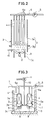
- FIGS. 2 and 3 illustrate the second embodiment of the invention.
- a plurality of filter units 2 are arranged within the treating tank 1.
- An air blowing pipe 10 is led into second casing member 3b to open therein.
- each filter unit 2 comprises a plurality of filter membrane modules 4 arranged in a casing 3 and is disposed in the treating tank 1, it is possible to arrange filter membrane modules directly within the treating tank 1 without using casing 3. In that case, filter plates of outermost filter membrane modules 4 may be utilized as a casing. It is also noted that although, in the embodiment, air blowing pipe 10 is open within second casing member 3b, it is possible to arrange that the air blowing pipe 10 communicates with the interior of smaller casing member 3c.
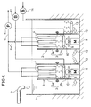
- FIG. 4 illustrates the third embodiment wherein, as is the case with the FIG. 3 embodiment, a plurality of filter units 2, or casings 3, are arranged in the treating tank 1, each casing 3 having a plurality of filter membrane modules 4 arranged therein.
- No smaller casing member 3c is provided, but instead second casing member 3b is extended to the bottom of the treating tank 1, there being disposed a drive motor 8 and an agitating element 9 in the second casing member 3b.
- Shown at 12 is an inlet port for entry into the casing 3 of water to be treated.
- an air blowing pipe 10 is provided within casing 3 as in the FIG. 2 embodiment and, in addition, another air blowing pipe 13 is disposed outside the casing 3.
- Designated by 14 is a blower. Therefore, in case that the air supply from the air blowing pipe 10 in the casing 3 falls short of the oxygen requirement for biological treatment, such amount of air as will match the B O D concentration of the water being treated is blown from said another air blowing pipe 10.
- FIGS. 5 and 6 illustrate the fourth embodiment of the invention and, in particular, a specific form of connection of filter membrane modules 4 with casing 3 in each filter unit 2.
- an element 21 which constitutes a filter membrane module 4 comprises a filter plate 22 covered on both sides with filter membranes 23.
- the filter plate 22 is formed in its interior with a treated-water flow passage 24 which is open at both sides of the filter plate 22.
- each casing 3 which is of rectangular configuration are formed guide grooves 26 for receiving the filter membrane modules 4, at predetermined intervals ⁇ in the direction in which the filter membrane modules 4 are arranged in parallel, so that individual filter membrane modules 4 are held in corresponding guide grooves 26.
- the predetermined interval ⁇ is set to a distance of more than 6 mm but less than 10 mm.
- the water being treated is allowed to flow as an upward stream under the air lift action of air jet from the air blowing pipe while being subjected to the agitation effect of the agitating element, the water being thus allowed to flow into gaps ⁇ between individual filter membrane modules 4.
- Each filter membrane module 4 sucks water-being-treated through its filter membrane 23 under negative pressure from suction pipe 6.
- Particulate substances present in water being treated are prevented by filter membrane 23 from passing therethrough, with the result that they deposit in cake form on the surface of the filter membrane 23, whereas treated water, or water that has passed through the filter membrane 23, is received into the suction pipe 6 after its passage through treated-water flow passage 24 and branch pipe 6a.
- Cake that has deposited on the surface of filter membrane 23 is separated from the membrane surface by upward agitation current of water being treated.
- the gap ⁇ between adjacent filter membranes 23 in each set of filter membrane modules 4 arranged in parallel spaced relation is less than 6 mm, the flow path defined by the gap ⁇ is so narrow that cake jamming is easily caused due to cake layer growth on the membrane surface and separated cake mass, the flow path being thereby blocked. If the gap ⁇ is more than 10 mm, the effect of shearing force exerted on cake layer by a combination of upward current flow velocity and air bubbles may be reduced.
- gap ⁇ is set to a level of more than 6 mm but less than 10 mm it is possible to eliminate the possibility of cake jamming in the inter-membrane flow path defined by gap ⁇ and to permit cake layers to be effectively acted upon by both air bubbles and the flow velocity of upward current flowing through the flow passage between adjacent membrane surfaces, so that the energy requirement for membrane surface cleaning may be reasonably reduced.
- a plurality of filter membrane modules 4 are arranged in position by being fitted in corresponding guide grooves 26 formed in frame member 25, whereby the filter membrane modules 4 are integrally held in the frame member 25. Therefore, for the purpose of maintenance of filter membrane modules 4, any filter membrane module 4 which requires maintenance can be removed simply by pulling it off the frame member 25 while other filter membrane modules 4 are held in position as they are.
- each filter membrane module 4 can be positively and uniformly cleaned by an agitation current produced by agitation means. Therefore, even when the magnitude of air blow from an air blowing pipe or the like is to be adjusted correspondingly to the B O D concentration of the water being treated, filter membrane modules can be uniformly and accurately cleaned with respect to their entire membrane surfaces, independent of the rate and velocity of air blow.
- FIG. 7 is a sectional view of essential part of the fifth embodiment of the invention.
- a plurality of filter units 2 are arranged within the treating tank 1, each filter unit 2 comprising a top- and bottom-opened cylindrical casing 3, and a plurality of filter membrane modules 4 of plate-like shape which are vertically arranged in equispaced relation within the casing 3.
- the casing 3 is of a vertically splittable, two-part construction having first and second casing members 3a, 3b.
- a discharge pipe 41 is mounted at the top end of the first casing member 3a or upper casing member.
- Character H represents the length of the first casing member 3a.
- Length Z of the second casing member 3b is dimensioned substantially longer than that of the comparable casing member in the earlier described first and second embodiments.
- Air blow pipe 10 is open at the level of the base of a flared lower end opening of the second casing member 3b, which flared opening is intended to lessen the fluid resistance involved.
- length Z should preferably be at least 500 mm.
- the air blow requirement may be of the order of 0.5-1.0 (m3 / m3 ⁇ min) per unit sectional area of second casing member 3b (which value is extremely large as compared with that in the case of ordinary activated sludge treatment), but it must be noted in this conjunction that if the length Z of second casing member 3b is set excessively large, coalescence of air bubbles may result and the air lift effect of air bubbles will be decreased.
- the length Z of second casing member 3b should preferably be not more than 2 m at most.
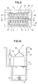
- FIGS. 8 through 12 illustrate the sixth embodiment of the invention.
- filter membrane modules 4 are individually fitted in guide grooves 26 formed in frame member 25 in same way as those shown in FIGS. 5 and 6.
- a pair of hooks 34 for lifting the filter membrane module 4.
- Filter membrane modules 4 are submerged in the trating tank 1 as shown in FIGS. 9 to 11.
- An opereator's cabin 36 is provided above the treating tank 1, and a hanger support bar 37 is disposed above the operator's cabin 36 and along a center line extending between opposite top ends of inner walls of the cabin.
- the hanger support bar 37 is fitted with hooks 38 which are positioned at suitable intervals, so that filter membrane modules 4 lifted from corresponding guide grooves 26 can be suspended from the hooks.
- Hooks 34 of the filter membrane modules 4 which have become visible as a result of this partial removal are caught up by wire 40 and the filter membrane modules 4 are then lifted along the guide grooves 26. Then, while holding the filter membrane modules 4 in such condition that their lower ends remain engaged about 10 to 20 mm with the guide grooves 26, lifting operation with respect to the filter membrane modules 4 is stopped, and wire 40 is caused to be engaged by hooks 38 on the hanger support bar 37.
- filter membrane modules 4 are supported at their upper ends in suspension from the hanger support bar 37 and are held in engagement at their lower ends with guide grooves 26; therefore, filter membrane modules 4 are held in suspension in unshakably secured condition. While being held in such condition, filter membranes of the modules 4 are mechanically or manually cleaned, which insures easy cleaning. As such, there is no possibility of any other facility getting wet or getting spoiled by waste water from cleaning operation. Further, the fact that less movement of filter membrane elements is required in cleaning operation provides an advantage that membranes are less liable to damage.
- a nozzle for jetting cleaning water may be attached to the hanger support bar 37 or disposed adjacent the support bar 37 in order to wash away cake layers of activated sludge with high pressure washing water as a preliminary step of cleaning.
- cleaning operation may be carried out by lifting all filter membrane modules 4 at one time
- the fact that filter membrane modules 4 are fitted in guide grooves 2 at intervals of 6 to 10 mm as earlier described permits three or four modules to be lifted each time for being supported in suspension from the hanger support bar 37, in which case the filter membrane modules 4 so supported may be spaced from each other at a distance of 50 to 100 mm; this greatly facilitates machine-cleaning operation.
- the hanger support bar 37 shown in FIG. 11 is fixed to inner walls of the operator's cabin, but as an alternative it may be of such removable type as shown in FIG. 12 so that it may not interfere with usual operation of the treating tank 1 other than cleaning operation.
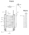
- FIGS. 13 and 14 illustrate another example of filter membrane module arrangement.
- filter membrane modules 4 are of a horizontal tubular configuration and are arranged in plurality both vertically and horizontally at intervals ⁇ of 6 to 10 mm. Shown by 3d is a tubular plate. A space 42 is defined between casing member 3a and such tubular plate 3d, and a suction pipe 6 is in communication with the space 42.
Landscapes
- Chemical & Material Sciences (AREA)
- Engineering & Computer Science (AREA)
- Water Supply & Treatment (AREA)
- Life Sciences & Earth Sciences (AREA)
- Chemical Kinetics & Catalysis (AREA)
- Biodiversity & Conservation Biology (AREA)
- Microbiology (AREA)
- Hydrology & Water Resources (AREA)
- Environmental & Geological Engineering (AREA)
- Organic Chemistry (AREA)
- Separation Using Semi-Permeable Membranes (AREA)
Abstract
Description
- The present invention relates to an activated sludge treating apparatus for use in treating wastewater, such as gray water and sewage.
- In known activated sludge treating apparatuses of this type, a plurality of filter membrane modules are vertically arranged in parallel spaced relation within a treating tank, whereby the water to be treated is separated into solid and liquid by being passed through the filter membrane modules so that water that has passed through the filter membrane modules is extracted as treated water. In such known type of apparatus for treatment of activated sludge, a diffused aeration pipe having a plurality of jet holes is disposed at a level below the filter membrane modules in order to prevent deposition and growth of cake and gel layers on the outer surfaces of the filter membrane modules. The air lift action of air blow from the diffused aeration pipe serves to create upward flowing agitation currents of both gas and liquid phases which are utilized to clean the membrane surfaces of the filter membrane modules.
- According to such arrangement, it is possible to enhance the cleaning effect of such agitation currents on the filter membrane modules to a certain extent by increasing the amount of air blow from the diffused aeration pipe. However, this involves the following problems. Increased air blow from the diffused aeration pipe may result in excessive aeration with respect to the water being treated and, especially where the water being treated contains ammonia, the pH value of the water will be excessively lowered, the operation of activated sludge treating being thus unfavorably affected.
- Another problem is that when the rate of air blow exceeds a specific value, for example, about 1 (m³ / m³ · min., where denominator m³ represents cross-sectional area of flow path of gas -liquid phase currents), the air lift action of air blow is decreased due to air-bubble coalescence, which results in decreased energy efficiency. A further problem is that the distance between the diffused aeration pipe and the lower end of the filter membrane modules is so short that air blown from the diffused aeration pipe is unlikely to be uniformly dispersed, which fact will not only tend to decrease the air lift effect of air blow but may tend to create some dead space in filter membrane modules which will remain isolated from gas -liquid phase current flow. As a consequence, cake layers or the like will deposit and grow on such portion of filter membrane modules, thus lowering the flux of the filter membrane modules.
- The present invention is directed to overcoming the foregoing problems, and accordingly it is a primary object of the invention to provide a membrane-separation type activated sludge treating apparatus which eliminates the possibility of any dead space being created in filter membrane modules, is well adapted for uniform cleaning of the entire membrane surfaces of filter membrane modules such that cake layers or the like can be positively prevented from depositing and growing on the membrane surfaces, and which involves less power requirement.
- In order to accomplish this object, according to the invention there is provided an activated sludge treating apparatus comprising:
a treating tank in which water to be treated is stored;
a plurality of filter membrane modules vertically arranged in spaced relation within the treating tank for separating said water to be treated into solid and liquid by passing the water therethrough, thereby to extract treated water; and
means disposed at a level below said filter membrane modules for agitating said water to be treated. - According to such arrangement, the entire membrane surface of each filter membrane module can be uniformly and positively cleaned by agitation currents created by the agitating means. Therefore, even when the magnitude of air blow from an air blowing pipe or the like is to be adjusted according to the B O D concentration of the water to be treated, the entire membrane surface of each filter membrane module can be uniformly and positively cleaned without being influenced by the rate and velocity of air blow.
-
- FIG. 1 is a general view in section of an activated sludge treating apparatus representing a first embodiment of the present invention;
- FIG. 2 is a front view showing an essential part of an activated sludge treating apparatus representing a second embodiment of the invention;
- FIG. 3 is a side view of the treating apparatus in FIG. 2;
- FIG. 4 is a general view in section of an activated sludge treating apparatus representing a third embodiment of the invention;
- FIG. 5 is a plan view showing the arrangement of filter membrane modules in an activated sludge treating apparatus representing a fourth embodiment of the invention;
- FIG. 6 is a sectional view showing one of the filter membrane modules in FIG. 5;
- FIG. 7 is a sectional view showing an essential part of a fifth embodiment of the invention;
- FIG. 8 is a perspective view showing an essential part of an activated sludge treating apparatus representing a six embodiment of the invention;
- FIG. 9 is a plan view showing filter membrane modules in the FIG. 8 apparatus as supported in suspension;
- FIG. 10 is a section taken along line A - A in FIG. 9;
- FIG. 11 is a section taken along line B - B in FIG. 9;
- FIG. 12 is a schematic view showing another form of the hanger support bar for supporting filter membrane modules in suspension as seen in FIG. 8;
- FIG. 13 is another form of filter membrane module arrangement; and
- FIG. 14 is a section taken along line C - C in FIG. 13;
- FIG. 1 illustrates the first embodiment of the invention. A plurality of
filter units 2 are arranged in a treatingtank 1. Eachfilter unit 2 includes acylindrical casing 3 which is open at its top and bottom portions, and a plurality offilter membrane modules 4 of plate-like shape which are vertically arranged in equispaced relation within thecasing 3. Thecasing 3 is of a vertically splitable, two-part construction such that it has first andsecond casing members Filter membrane modules 4 are arranged in thefirst casing member 3a, and asmaller casing member 3c of cylindrical configuration is provided in thesecond casing member 3b. - Each
filter membrane module 4 is removably disposed infirst casing member 3a so that it may be drawn upward for removal. Therefore, filter membrane modules in may be removed upward one by one for being individually cleaned and/or replaced. It is possible to separatefirst casing member 3a or the upper casing member fromsecond casing member 3b or the lower casing member, thereby to remove thefirst casing member 3a from the treatingtank 1 with the plurality offilter membrane modules 4 as attached to thefirst casing member 3b, so that thefilter membrane modules 4 may be individually cleaned and/or replaced. Eachfilter membrane module 4 is connected at its upper end via abranch pipe 6a to asuction pipe 6 which is fitted with asuction pump 5 at a suitable location. Awastewater supply pipe 7 for feeding wastewater into the treatingtank 1 is open at a location above the treatingtank 1. - An
agitating element 9 having adrive motor 8 is disposed within thesmaller casing 3c which is positioned below thefilter membrane modules 4. Provided within the treatingtank 1 is an air-blowingpipe 10 which extends from the top side of thetank 1 to the bottom side of thetank 1; and ablower 11 is disposed on the proximal end side of theair blowing pipe 10 at a location outside thetank 1. - According to the above described arrangement, wastewater, such as gray water and sewage, which is introduced from the
wastewater supply pipe 7 into the treatingtank 1, is mixed with activated sludge present in thetank 1 for being treated therein. The water being treated is exposed to air blown by theblower 11 through a plurality of orifices at the tip of theair blowing pipe 10 and is digested by activated sludge. - The water being treated is sucked by the
suction pump 5 throughfilter membrane modules 4 and thesuction pipe 6, being separated into solid and liquid as it passes through thefilter membrane modules 4, and that part of the water which has passed through thefilter membrane modules 4 is extracted as treated water. - Agitation currents created by the
agitating element 9 are allowed to flow upward between adjacentfilter membrane modules 4 and along membrane surfaces. Such agitation current provides positive cleaning of the entire membrane surface of eachfilter membrane module 4. - Even when the magnitude of air blow from the
air blowing pipe 10 is adjusted according to the B O D concentration of the water to be treated, the entire membrane surface of eachfilter membrane module 4 can be uniformly and positively cleaned by the agitating action of theagitating element 9 without being influenced by the rate of air blow and jet velocity thereof. - Air bubbles blown from the
air blowing pipe 10 are divided into fine bubbles by the agitating action of theagitating element 9. This results in improved efficiency of dissolution of the oxygen content of air bubbles into the water being treated, so that improved biochemical treatment effect can be achieved. In addition, fine air bubbles serve to produce further turbulence effect and inhibit development of vibrations. Thus, after all, water treatment in the treatingtank 1 can be satisfactorily accomplished whilefilter membrane modules 4 are allowed to retain their serviceability for a longer period. - FIGS. 2 and 3 illustrate the second embodiment of the invention.
- As shown, a plurality of
filter units 2 are arranged within the treatingtank 1. Anair blowing pipe 10 is led intosecond casing member 3b to open therein. - According to such arrangement, although the distance between the level at which the air blowing pipe is open and the lower end of
first casing member 3a is relatively small, air blown from the open end of theair blowing pipe 10 is caught up into agitation currents created by agitatingelement 9 in thesecond casing member 3b, so that the air is uniformly dispersed in the form of fine air bubbles (of about 3 - 4 mm in diameter) over a wide area. Such fine air bubbles flow upward between adjacentfilter membrane modules 4 and along the membrane surfaces thereof. As a result, upward flowing agitation currents of two phases, gas and liquid, are created, whereby entire membrane surfaces of individualfilter membrane modules 4 can be positively cleaned. - Although, in this embodiment, each
filter unit 2 comprises a plurality offilter membrane modules 4 arranged in acasing 3 and is disposed in the treatingtank 1, it is possible to arrange filter membrane modules directly within the treatingtank 1 without usingcasing 3. In that case, filter plates of outermostfilter membrane modules 4 may be utilized as a casing. It is also noted that although, in the embodiment,air blowing pipe 10 is open withinsecond casing member 3b, it is possible to arrange that theair blowing pipe 10 communicates with the interior ofsmaller casing member 3c. - FIG. 4 illustrates the third embodiment wherein, as is the case with the FIG. 3 embodiment, a plurality of
filter units 2, orcasings 3, are arranged in the treatingtank 1, eachcasing 3 having a plurality offilter membrane modules 4 arranged therein. Nosmaller casing member 3c is provided, but instead second casingmember 3b is extended to the bottom of the treatingtank 1, there being disposed adrive motor 8 and an agitatingelement 9 in thesecond casing member 3b. Shown at 12 is an inlet port for entry into thecasing 3 of water to be treated. - In the treating
tank 1, anair blowing pipe 10 is provided withincasing 3 as in the FIG. 2 embodiment and, in addition, anotherair blowing pipe 13 is disposed outside thecasing 3. Designated by 14 is a blower. Therefore, in case that the air supply from theair blowing pipe 10 in thecasing 3 falls short of the oxygen requirement for biological treatment, such amount of air as will match the B O D concentration of the water being treated is blown from said anotherair blowing pipe 10. - FIGS. 5 and 6 illustrate the fourth embodiment of the invention and, in particular, a specific form of connection of
filter membrane modules 4 withcasing 3 in eachfilter unit 2. In these figures, anelement 21 which constitutes afilter membrane module 4 comprises afilter plate 22 covered on both sides withfilter membranes 23. Thefilter plate 22 is formed in its interior with a treated-water flow passage 24 which is open at both sides of thefilter plate 22. - In order to permit a plurality of
filter membrane modules 4 to be integrally held in position, it is arranged that on the inner surface of aframe member 25 of eachcasing 3 which is of rectangular configuration are formedguide grooves 26 for receiving thefilter membrane modules 4, at predetermined intervals α in the direction in which thefilter membrane modules 4 are arranged in parallel, so that individualfilter membrane modules 4 are held incorresponding guide grooves 26. The predetermined interval α is set to a distance of more than 6 mm but less than 10 mm. - According to such arrangement, as is the case with the foregoing embodiments, the water being treated is allowed to flow as an upward stream under the air lift action of air jet from the air blowing pipe while being subjected to the agitation effect of the agitating element, the water being thus allowed to flow into gaps α between individual
filter membrane modules 4. Eachfilter membrane module 4 sucks water-being-treated through itsfilter membrane 23 under negative pressure fromsuction pipe 6. - Particulate substances present in water being treated are prevented by
filter membrane 23 from passing therethrough, with the result that they deposit in cake form on the surface of thefilter membrane 23, whereas treated water, or water that has passed through thefilter membrane 23, is received into thesuction pipe 6 after its passage through treated-water flow passage 24 andbranch pipe 6a. Cake that has deposited on the surface offilter membrane 23 is separated from the membrane surface by upward agitation current of water being treated. - In this case, if the gap α between
adjacent filter membranes 23 in each set offilter membrane modules 4 arranged in parallel spaced relation is less than 6 mm, the flow path defined by the gap α is so narrow that cake jamming is easily caused due to cake layer growth on the membrane surface and separated cake mass, the flow path being thereby blocked. If the gap α is more than 10 mm, the effect of shearing force exerted on cake layer by a combination of upward current flow velocity and air bubbles may be reduced. - Therefore, by setting gap α to a level of more than 6 mm but less than 10 mm it is possible to eliminate the possibility of cake jamming in the inter-membrane flow path defined by gap α and to permit cake layers to be effectively acted upon by both air bubbles and the flow velocity of upward current flowing through the flow passage between adjacent membrane surfaces, so that the energy requirement for membrane surface cleaning may be reasonably reduced.
- As stated above, a plurality of
filter membrane modules 4 are arranged in position by being fitted incorresponding guide grooves 26 formed inframe member 25, whereby thefilter membrane modules 4 are integrally held in theframe member 25. Therefore, for the purpose of maintenance offilter membrane modules 4, anyfilter membrane module 4 which requires maintenance can be removed simply by pulling it off theframe member 25 while otherfilter membrane modules 4 are held in position as they are. - According to the above described arrangement, the entire membrane surface of each
filter membrane module 4 can be positively and uniformly cleaned by an agitation current produced by agitation means. Therefore, even when the magnitude of air blow from an air blowing pipe or the like is to be adjusted correspondingly to the B O D concentration of the water being treated, filter membrane modules can be uniformly and accurately cleaned with respect to their entire membrane surfaces, independent of the rate and velocity of air blow. - FIG. 7 is a sectional view of essential part of the fifth embodiment of the invention. A plurality of
filter units 2 are arranged within the treatingtank 1, eachfilter unit 2 comprising a top- and bottom-openedcylindrical casing 3, and a plurality offilter membrane modules 4 of plate-like shape which are vertically arranged in equispaced relation within thecasing 3. Thecasing 3 is of a vertically splittable, two-part construction having first andsecond casing members discharge pipe 41 is mounted at the top end of thefirst casing member 3a or upper casing member. Character H represents the length of thefirst casing member 3a. Length Z of thesecond casing member 3b is dimensioned substantially longer than that of the comparable casing member in the earlier described first and second embodiments.Air blow pipe 10 is open at the level of the base of a flared lower end opening of thesecond casing member 3b, which flared opening is intended to lessen the fluid resistance involved. - According to such arrangement, wherein the length of the
second casing member 3b is dimensioned sufficiently large, air blown from the opening at the tip of theair blow pipe 10 will be dispersed in the form of fine air bubbles (of 3 - 4 mm in diameter) over the entire cross-sectional area of thesecond casing member 3b without using such an agitating element as is employed in the earlier described first and second embodiments. In order to insure uniform dispersion of air, length Z should preferably be at least 500 mm. - It is not necessarily the case that the greater the length Z of
second casing member 3b, the better. Where the FIG. 7 arrangement is employed in treating activated sludge of sewage or the like, the air blow requirement may be of the order of 0.5-1.0 (m³ / m³ · min) per unit sectional area ofsecond casing member 3b (which value is extremely large as compared with that in the case of ordinary activated sludge treatment), but it must be noted in this conjunction that if the length Z ofsecond casing member 3b is set excessively large, coalescence of air bubbles may result and the air lift effect of air bubbles will be decreased. More specifically, in the case of the arrangement employed in the first or second embodiment, even if the length Z ofsecond casing member 3b is relatively short, air bubbles can be uniformly dispersed and made finer because of the provision of the agitating element, but whereas in the case of the FIG. 7 arrangement in which no agitating element is provided, if length Z is too large, coalescence of air bubbles will occur in the process of upward flow of air bubbles within thesecond casing member 3b. If air bubble diameter is larger than 10 mm, air bubbles are no longer allowed to pass the gap between adjacentfilter membrane modules 4 and hence the air lift effect of air bubbles will be lowered. This in turn will cause drift, which may lead to flux degradation due to cake layer deposition. Therefore, the length Z ofsecond casing member 3b should preferably be not more than 2 m at most. - The power requirement for operation of the apparatus is 1.2 kWh / m³ per unit amount of treated water (amount of water that has passed through membrane) in the case of the foregoing first, second and third embodiments, whereas in the case of the fifth embodiment shown in FIG. 7, the power requirement may be reduced to 0.45 kWh / m³ under proper design conditions such that H = 1 m, Z = 1 m, and bore diameter of both first and second casings is 0.3 m.
- FIGS. 8 through 12 illustrate the sixth embodiment of the invention. In FIG. 8,
filter membrane modules 4 are individually fitted inguide grooves 26 formed inframe member 25 in same way as those shown in FIGS. 5 and 6. At opposite end portions of the top of eachfilter membrane module 4 there are provided a pair ofhooks 34 for lifting thefilter membrane module 4. -
Filter membrane modules 4 are submerged in thetrating tank 1 as shown in FIGS. 9 to 11. An opereator'scabin 36 is provided above the treatingtank 1, and ahanger support bar 37 is disposed above the operator'scabin 36 and along a center line extending between opposite top ends of inner walls of the cabin. Thehanger support bar 37 is fitted withhooks 38 which are positioned at suitable intervals, so thatfilter membrane modules 4 lifted from correspondingguide grooves 26 can be suspended from the hooks. - Nextly, method of cleaning the
filter membrane modules 4 will be explained. Whenfilter membrane modules 4, as submerged in the treatingtank 1, has been engaged in separating water-being-treated into activated sludge and treated water for a given period of time (three to four months), cake layers of activated sludge are formed on the membrane surface of eachfilter membrane module 4 despite the effect of upward flow currents created by agitatingelement 9 and the like. Therefore, in order to remove such cake layers, initially the water being treated is partially removed from the treatingtank 1 in which the level of the water being treated is about 20-50 cm above the upper ends offilter membrane modules 4 during usual operation, until the upper ends of thefilter membrane modules 4 have become visible.Hooks 34 of thefilter membrane modules 4 which have become visible as a result of this partial removal are caught up bywire 40 and thefilter membrane modules 4 are then lifted along theguide grooves 26. Then, while holding thefilter membrane modules 4 in such condition that their lower ends remain engaged about 10 to 20 mm with theguide grooves 26, lifting operation with respect to thefilter membrane modules 4 is stopped, andwire 40 is caused to be engaged byhooks 38 on thehanger support bar 37. - In this manner,
filter membrane modules 4 are supported at their upper ends in suspension from thehanger support bar 37 and are held in engagement at their lower ends withguide grooves 26; therefore,filter membrane modules 4 are held in suspension in unshakably secured condition. While being held in such condition, filter membranes of themodules 4 are mechanically or manually cleaned, which insures easy cleaning. As such, there is no possibility of any other facility getting wet or getting spoiled by waste water from cleaning operation. Further, the fact that less movement of filter membrane elements is required in cleaning operation provides an advantage that membranes are less liable to damage. - For the purpose of cleaning operation, a nozzle for jetting cleaning water (not shown) may be attached to the
hanger support bar 37 or disposed adjacent thesupport bar 37 in order to wash away cake layers of activated sludge with high pressure washing water as a preliminary step of cleaning. - Although cleaning operation may be carried out by lifting all
filter membrane modules 4 at one time, the fact thatfilter membrane modules 4 are fitted inguide grooves 2 at intervals of 6 to 10 mm as earlier described permits three or four modules to be lifted each time for being supported in suspension from thehanger support bar 37, in which case thefilter membrane modules 4 so supported may be spaced from each other at a distance of 50 to 100 mm; this greatly facilitates machine-cleaning operation. - The
hanger support bar 37 shown in FIG. 11 is fixed to inner walls of the operator's cabin, but as an alternative it may be of such removable type as shown in FIG. 12 so that it may not interfere with usual operation of the treatingtank 1 other than cleaning operation. - FIGS. 13 and 14 illustrate another example of filter membrane module arrangement. In this embodiment,
filter membrane modules 4 are of a horizontal tubular configuration and are arranged in plurality both vertically and horizontally at intervals α of 6 to 10 mm. Shown by 3d is a tubular plate. Aspace 42 is defined betweencasing member 3a and suchtubular plate 3d, and asuction pipe 6 is in communication with thespace 42.
Claims (10)
- An activated sludge treating apparatus comprising:
a treating tank in which water to be treated is stored;
a plurality of filter membrane modules vertically arranged in spaced relation within the treating tank for separating said water to be treated into solid and liquid by passing the water therethrough, thereby to extract treated water; and
means disposed at a level below said filter membrane modules for creating upward flow currents. - An activated sludge treating apparatus as set forth in claim 1, further comprising means for blowing air into the treating tank.
- An activated sludge treating apparatus as set forth in claim 2, further comprising a vertically extending cylindrical casing disposed below the filter membrane modules and having a length of more than 500 mm but less than 2000 mm, said air blowing means passing through a lower end wall portion of the casing to open therein.
- An activated sludge treating apparatus as set forth in claim 1, wherein:
said plurality of filter membrane modules and said means for creating upward flow currents are housed in the casing to form a filter unit; and
a plurality of filter units are arranged in said treating tank. - An activated sludge treating apparatus as set forth in claims 3 or 4, further comprising another air blowing means for blowing air into the treating tank at a location outside the casing.
- An activated sludge treating apparatus as set forth in claim 1, further comprising:
a frame member for housing the filter membrane modules; and
a plurality of guide grooves formed in said frame member for causing the filter membrane modules to be housed in said frame member and to be arranged parallel at predetermined intervals. - An activated sludge treating apparatus as set forth in claim 6, wherein said predetermined interval is more than 6 mm but less than 10 mm.
- An activated sludge treating apparatus as set forth in claim 1, wherein the filter membrane modules are of a tubular configuration.
- An activated sludge treating apparatus as set forth in claim 8, wherein the plurality of filter membrane modules are arranged at predetermined intervals, said interval being more than 6 mm but less than 10 mm.
- A method of cleaning the filter membrane modules in the activated sludge treating apparatus as claimed in claim 6, which comprises:
lifting the filter membrane modules along the guide grooves;
stopping said lifting operation while holding the filter membrane modules in such condition that their lower ends are in engagement with the guide grooves, then supporting the filter membrane modules in suspension; and
cleaning by washing the filter membrane modules thus lifted and supported in suspension.
Applications Claiming Priority (4)
| Application Number | Priority Date | Filing Date | Title |
|---|---|---|---|
| JP40334/91 | 1991-03-07 | ||
| JP3040334A JP3023928B2 (en) | 1991-03-07 | 1991-03-07 | Solid-liquid separator |
| JP219066/91 | 1991-08-30 | ||
| JP3219066A JPH0557158A (en) | 1991-08-30 | 1991-08-30 | Cleaning method of filtration membrane element |
Publications (3)
| Publication Number | Publication Date |
|---|---|
| EP0510328A2 true EP0510328A2 (en) | 1992-10-28 |
| EP0510328A3 EP0510328A3 (en) | 1992-12-02 |
| EP0510328B1 EP0510328B1 (en) | 1995-10-04 |
Family
ID=26379784
Family Applications (1)
| Application Number | Title | Priority Date | Filing Date |
|---|---|---|---|
| EP19920103240 Expired - Lifetime EP0510328B1 (en) | 1991-03-07 | 1992-02-26 | Apparatus for treating activated sludge |
Country Status (5)
| Country | Link |
|---|---|
| US (1) | US5192456A (en) |
| EP (1) | EP0510328B1 (en) |
| DE (1) | DE69205198T2 (en) |
| DK (1) | DK0510328T3 (en) |
| GR (1) | GR3018058T3 (en) |
Cited By (28)
| Publication number | Priority date | Publication date | Assignee | Title |
|---|---|---|---|---|
| US5248424A (en) * | 1990-08-17 | 1993-09-28 | Zenon Environmental Inc. | Frameless array of hollow fiber membranes and method of maintaining clean fiber surfaces while filtering a substrate to withdraw a permeate |
| WO1994011311A1 (en) * | 1992-11-19 | 1994-05-26 | Karsten Krogh Andersen | A purification system with filter for separation of activated sludge and treated water in a process tank |
| EP0605826A1 (en) * | 1992-12-24 | 1994-07-13 | Kubota Corporation | Adsorption/reaction equipment |
| EP0659694A1 (en) * | 1993-12-24 | 1995-06-28 | Stork Friesland B.V. | Membrane bioreactor with gas lift system |
| EP0662341A1 (en) * | 1994-01-07 | 1995-07-12 | Kubota Corporation | Filtration membrane module |
| EP0700713A1 (en) * | 1994-09-08 | 1996-03-13 | Kubota Corporation | Solid-liquid separator |
| EP0734758A1 (en) * | 1995-03-31 | 1996-10-02 | Mitsui Petrochemical Industries, Ltd. | Membrane device having means for charging the membranes |
| FR2741280A1 (en) * | 1995-11-22 | 1997-05-23 | Omnium Traitement Valorisa | METHOD OF CLEANING A IMMERING MEMBRANE TYPE FILTRATION FACILITY |
| EP0803274A1 (en) | 1996-04-26 | 1997-10-29 | WABAG Wassertechnische Anlagen GmbH | Process and apparatus for treatment of backwash water from a filter |
| DE19734759C1 (en) * | 1997-08-10 | 1998-08-27 | Chmiel Horst | Waste water treatment and assembly |
| KR100241588B1 (en) * | 1997-04-07 | 2000-02-01 | 조민호 | Water treating apparatus using membrane |
| EP0937494A3 (en) * | 1998-02-23 | 2000-03-01 | Kubota Corporation | Membrane separation system |
| WO2000009245A3 (en) * | 1998-08-12 | 2000-08-03 | Mitsubishi Rayon Co | Membrane assembly for solid-liquid separation, method of cleaning the same, and detergent |
| DE19648519C2 (en) * | 1996-11-23 | 2000-11-16 | Preussag Wassertechnik Gmbh | Process and system for material separation by means of membrane filtration |
| GB2355712A (en) * | 1999-06-26 | 2001-05-02 | Stephen Ferenc Mate | Sewage plant |
| US6376255B1 (en) | 1998-09-23 | 2002-04-23 | Wtw Wissenschaftlich-Technische Werkstaetten Gmbh | Apparatus and method for analyzing the amount of chemical substrates in a liquid |
| DE10141746C1 (en) * | 2000-09-05 | 2002-08-14 | Horst Chmiel | Purification of water using hollow fiber membrane bundles |
| EP1354632A1 (en) * | 2002-03-27 | 2003-10-22 | Gesellschaft für umweltkompatible Prozesstechnik mbH | Flotation process and apparatus containing a membrane |
| EP1433511A1 (en) * | 2002-12-19 | 2004-06-30 | Utisol Technologies AG | Filter device |
| WO2005118117A1 (en) * | 2004-05-28 | 2005-12-15 | Siemens Water Technologies Corp. | Retractable cantilever rack support |
| DE102004063879A1 (en) * | 2004-12-03 | 2006-06-08 | Hans Huber Ag Maschinen- Und Anlagenbau | Filtering device and method for clarifying polluted liquids |
| US7279215B2 (en) | 2003-12-03 | 2007-10-09 | 3M Innovative Properties Company | Membrane modules and integrated membrane cassettes |
| NL1031926C2 (en) * | 2006-05-31 | 2007-12-03 | X Flow Bv | Device with a bioreactor and membrane filtration module for treating an incoming fluid. |
| EP1911510A3 (en) * | 1998-08-12 | 2008-06-11 | Mitsubishi Rayon Co. Ltd. | A membrane separator assembly |
| FR2924111A1 (en) * | 2007-11-28 | 2009-05-29 | Otv Sa | Installation for biological treatment of water for drinking, comprises biological reactor housing a membrane, water routing unit, unit for adding powdery material inside reactor, unit for recuperation of treated water, and agitation unit |
| EP2143691A3 (en) * | 2008-07-11 | 2010-08-11 | Helmut Prieske | Membrane bioreactor and method for processing waste water |
| FR3030481A1 (en) * | 2014-12-23 | 2016-06-24 | Bfg Env Tech | MOBILE DEVICE FOR THE BIOLOGICAL TREATMENT OF BIOREACTOR TYPE WASTEWATER. |
| EP2980026A4 (en) * | 2013-03-27 | 2016-11-30 | Kubota Kk | ELEVATION APPARATUS, ELEVATION ASSEMBLY AND WATER TREATMENT FACILITY |
Families Citing this family (117)
| Publication number | Priority date | Publication date | Assignee | Title |
|---|---|---|---|---|
| US5639373A (en) | 1995-08-11 | 1997-06-17 | Zenon Environmental Inc. | Vertical skein of hollow fiber membranes and method of maintaining clean fiber surfaces while filtering a substrate to withdraw a permeate |
| AU671803B2 (en) * | 1991-08-07 | 1996-09-12 | Siemens Industry, Inc. | Concentration of solids in a suspension using hollow fibre membranes |
| DE4209588C2 (en) * | 1992-03-25 | 1995-02-02 | Guetling Gmbh | Oil separator with integrated microfiltration device and method for cleaning it |
| GB9210980D0 (en) * | 1992-05-22 | 1992-07-08 | Dow Danmark | Cassette membrane system and method of use for low pressure separations |
| US5651888A (en) * | 1992-12-16 | 1997-07-29 | Kubota Corporation | Filtration membrane cartridge |
| JP3119006B2 (en) * | 1993-01-07 | 2000-12-18 | 富士電機株式会社 | Filtration concentration device and filtration concentration method |
| FR2713220B1 (en) * | 1993-11-30 | 1996-03-08 | Omnium Traitement Valorisa | Installation of water purification with submerged filter membranes. |
| US7037426B2 (en) * | 2000-05-04 | 2006-05-02 | Zenon Environmental Inc. | Immersed membrane apparatus |
| US8852438B2 (en) * | 1995-08-11 | 2014-10-07 | Zenon Technology Partnership | Membrane filtration module with adjustable header spacing |
| US6863823B2 (en) * | 2001-03-23 | 2005-03-08 | Zenon Environmental Inc. | Inverted air box aerator and aeration method for immersed membrane |
| US20020134740A1 (en) * | 2001-03-23 | 2002-09-26 | Pierre Cote | Inverted air box aerator and aeration method for immersed membrane |
| US20040238432A1 (en) * | 1995-08-11 | 2004-12-02 | Mailvaganam Mahendran | Membrane filtration module with adjustable header spacing |
| DE69624492T2 (en) * | 1995-08-11 | 2003-06-26 | Zenon Environmental Inc., Oakville | VERTICAL STRAND OF HOLLOW FIBER MEMBRANES AND METHOD FOR MAINTAINING CLEAN FIBER SURFACES |
| US7087173B2 (en) * | 1995-08-11 | 2006-08-08 | Zenon Environmental Inc. | Inverted cavity aerator for membrane module |
| US5651889A (en) * | 1996-03-25 | 1997-07-29 | Mitsui Petrochemical Industries, Ltd. | Sludge treatment membrane apparatus |
| CN1060510C (en) * | 1996-10-08 | 2001-01-10 | 张鸣山 | Separation promoter applied to separation of octadecanoic unsaturated fatty acid in grease |
| US20040232076A1 (en) * | 1996-12-20 | 2004-11-25 | Fufang Zha | Scouring method |
| EP0952885B1 (en) * | 1996-12-20 | 2010-09-22 | Siemens Water Technologies Corp. | Scouring method |
| US6641733B2 (en) * | 1998-09-25 | 2003-11-04 | U. S. Filter Wastewater Group, Inc. | Apparatus and method for cleaning membrane filtration modules |
| TW422736B (en) * | 1998-04-24 | 2001-02-21 | Mitsui Zosen Engineering Kk | Method and apparatus for membrane treatment |
| TWI222895B (en) * | 1998-09-25 | 2004-11-01 | Usf Filtration & Separations | Apparatus and method for cleaning membrane filtration modules |
| US6706189B2 (en) | 1998-10-09 | 2004-03-16 | Zenon Environmental Inc. | Cyclic aeration system for submerged membrane modules |
| US6550747B2 (en) | 1998-10-09 | 2003-04-22 | Zenon Environmental Inc. | Cyclic aeration system for submerged membrane modules |
| US20040007527A1 (en) * | 1998-11-23 | 2004-01-15 | Zenon Environmental Inc. | Membrane filtration device and process |
| CA2290053C (en) | 1999-11-18 | 2009-10-20 | Zenon Environmental Inc. | Immersed membrane module and process |
| US6156200A (en) * | 1998-12-08 | 2000-12-05 | Usf Filtration & Separations Group, Inc. | Gas-scrubbed hollow fiber membrane module |
| AUPP985099A0 (en) * | 1999-04-20 | 1999-05-13 | Usf Filtration And Separations Group Inc. | Membrane filtration manifold system |
| US20010052494A1 (en) * | 1999-10-25 | 2001-12-20 | Pierre Cote | Chemical cleaning backwash for normally immersed membranes |
| JP4713801B2 (en) | 1999-11-18 | 2011-06-29 | ジーイー・ゼノン・ユーエルシー | Immersion type thin film elements and modules |
| AUPQ680100A0 (en) * | 2000-04-10 | 2000-05-11 | Usf Filtration And Separations Group Inc. | Hollow fibre restraining system |
| DE10045227C1 (en) * | 2000-09-13 | 2002-02-07 | Vosenkaul Klaus | Membrane filter for water treatment uses capillary membrane fibre bundle projecting into untreated water and fitting into permeate collection space at opposite end |
| DE20016417U1 (en) * | 2000-09-21 | 2002-02-14 | Wehrle-Werk AG, 79312 Emmendingen | Device for separating liquid and solid from a suspension |
| AUPR064800A0 (en) * | 2000-10-09 | 2000-11-02 | Usf Filtration And Separations Group Inc. | Improved membrane filtration system |
| AUPR094600A0 (en) * | 2000-10-23 | 2000-11-16 | Usf Filtration And Separations Group Inc. | Fibre membrane arrangement |
| AUPR143400A0 (en) * | 2000-11-13 | 2000-12-07 | Usf Filtration And Separations Group Inc. | Modified membranes |
| US20050218074A1 (en) * | 2004-04-06 | 2005-10-06 | Pollock David C | Method and apparatus providing improved throughput and operating life of submerged membranes |
| AUPR421501A0 (en) * | 2001-04-04 | 2001-05-03 | U.S. Filter Wastewater Group, Inc. | Potting method |
| AUPR584301A0 (en) * | 2001-06-20 | 2001-07-12 | U.S. Filter Wastewater Group, Inc. | Membrane polymer compositions |
| AUPR692401A0 (en) * | 2001-08-09 | 2001-08-30 | U.S. Filter Wastewater Group, Inc. | Method of cleaning membrane modules |
| AUPR774201A0 (en) * | 2001-09-18 | 2001-10-11 | U.S. Filter Wastewater Group, Inc. | High solids module |
| ATE333318T1 (en) * | 2001-11-16 | 2006-08-15 | Us Filter Wastewater Group Inc | METHOD FOR CLEANING MEMBRANES |
| US7247238B2 (en) * | 2002-02-12 | 2007-07-24 | Siemens Water Technologies Corp. | Poly(ethylene chlorotrifluoroethylene) membranes |
| US6743362B1 (en) | 2002-06-17 | 2004-06-01 | Enviroquip Inc. | Sewage treatment process |
| AUPS300602A0 (en) * | 2002-06-18 | 2002-07-11 | U.S. Filter Wastewater Group, Inc. | Methods of minimising the effect of integrity loss in hollow fibre membrane modules |
| US6841083B2 (en) * | 2002-06-27 | 2005-01-11 | Ethicon, Inc. | Device and process for improved scouring efficiency |
| AU2002950934A0 (en) * | 2002-08-21 | 2002-09-12 | U. S. Filter Wastewater Group, Inc. | Aeration method |
| CA2501628C (en) * | 2002-10-10 | 2012-12-04 | U.S. Filter Wastewater Group, Inc. | A filtration and backwashing arrangement for membrane modules |
| AU2002953111A0 (en) * | 2002-12-05 | 2002-12-19 | U. S. Filter Wastewater Group, Inc. | Mixing chamber |
| ATE395127T1 (en) * | 2003-03-05 | 2008-05-15 | Hydranautics | SUBMERSIBLE MEMBRANE MODULE WITH INTERCHANGEABLE MEMBRANE ELEMENTS |
| US20040262209A1 (en) * | 2003-04-25 | 2004-12-30 | Hiroyuki Umezawa | Filtration apparatus |
| US6986428B2 (en) * | 2003-05-14 | 2006-01-17 | 3M Innovative Properties Company | Fluid separation membrane module |
| AU2003903507A0 (en) | 2003-07-08 | 2003-07-24 | U. S. Filter Wastewater Group, Inc. | Membrane post-treatment |
| US8268176B2 (en) | 2003-08-29 | 2012-09-18 | Siemens Industry, Inc. | Backwash |
| AU2004289373B2 (en) | 2003-11-14 | 2010-07-29 | Evoqua Water Technologies Llc | Improved module cleaning method |
| US20070051679A1 (en) * | 2004-02-27 | 2007-03-08 | Adams Nicholas W H | Water filtration using immersed membranes |
| US8758621B2 (en) | 2004-03-26 | 2014-06-24 | Evoqua Water Technologies Llc | Process and apparatus for purifying impure water using microfiltration or ultrafiltration in combination with reverse osmosis |
| WO2005107929A2 (en) * | 2004-04-22 | 2005-11-17 | Siemens Water Technologies Corp. | Filtration apparatus comprising a membrane bioreactor and a treatment vessel for digesting organic materials |
| US7122121B1 (en) | 2004-05-28 | 2006-10-17 | Jiang Ji | Advanced submerged membrane modules, systems and processes |
| JP2008504122A (en) * | 2004-07-02 | 2008-02-14 | シーメンス・ウォーター・テクノロジーズ・コーポレーション | Gas transport membrane |
| EP1773477B1 (en) | 2004-07-05 | 2011-09-07 | Siemens Water Technologies Corp. | Hydrophilic membranes |
| NZ588094A (en) | 2004-08-20 | 2012-04-27 | Siemens Water Tech Corp | Potting head for hollow fibre filter module |
| AU2005282211B2 (en) * | 2004-09-07 | 2011-04-21 | Evoqua Water Technologies Llc | Reduction of backwash liquid waste |
| US8506806B2 (en) | 2004-09-14 | 2013-08-13 | Siemens Industry, Inc. | Methods and apparatus for removing solids from a membrane module |
| EP1807181A4 (en) | 2004-09-15 | 2009-04-22 | Siemens Water Tech Corp | Continuously variable aeration |
| US7118674B2 (en) | 2004-10-14 | 2006-10-10 | Itt Manufacturing Enterprises, Inc. | Energy-efficient biological treatment with membrane filtration |
| US7297278B2 (en) * | 2004-10-20 | 2007-11-20 | Baker Hughes Incorporated | Methods for removing metals from water |
| US7591950B2 (en) * | 2004-11-02 | 2009-09-22 | Siemens Water Technologies Corp. | Submerged cross-flow filtration |
| EP1819426A4 (en) * | 2004-11-02 | 2009-08-12 | Siemens Water Tech Corp | Submerged cross-flow filtration |
| US20060108275A1 (en) * | 2004-11-08 | 2006-05-25 | Cote Pierre L | Membrane filtration assemblies for sand filter retrofit |
| MY141919A (en) * | 2004-12-03 | 2010-07-30 | Siemens Water Tech Corp | Membrane post treatment |
| US20060118487A1 (en) * | 2004-12-07 | 2006-06-08 | Adams Nicholas W H | Membrane filtration process |
| ATE549076T1 (en) | 2004-12-24 | 2012-03-15 | Siemens Industry Inc | CLEANING IN MEMBRANE FILTRATION SYSTEMS |
| CA2591580A1 (en) | 2004-12-24 | 2006-06-29 | Siemens Water Technologies Corp. | Simple gas scouring method and apparatus |
| US20060191837A1 (en) * | 2005-02-28 | 2006-08-31 | Alfa Laval Corporate Ab | Permeate spacer module |
| AU2006217128B2 (en) * | 2005-02-28 | 2011-08-11 | Alfa Laval Corporate Ab | Permeate spacer module |
| CN101184548B (en) | 2005-04-29 | 2011-10-05 | 西门子水技术公司 | Chemical clean for membrane filter |
| WO2006119484A1 (en) * | 2005-05-03 | 2006-11-09 | Watersmart Corp. | Graywater treatment system and method |
| US7147777B1 (en) | 2005-05-09 | 2006-12-12 | Eimco Water Technologies Llc | Wastewater treatment system with membrane separators and provision for storm flow conditions |
| NZ563980A (en) * | 2005-06-20 | 2011-07-29 | Siemens Water Tech Corp | Cross linking treatment of polymer membranes |
| WO2007006104A1 (en) | 2005-07-14 | 2007-01-18 | Siemens Water Technologies Corp. | Monopersulfate treatment of membranes |
| CN101287538B (en) | 2005-08-22 | 2013-03-06 | 西门子工业公司 | An assembly for water filtration using a tube manifold to minimise backwash |
| WO2007044415A2 (en) | 2005-10-05 | 2007-04-19 | Siemens Water Technologies Corp. | Method and apparatus for treating wastewater |
| US7563363B2 (en) | 2005-10-05 | 2009-07-21 | Siemens Water Technologies Corp. | System for treating wastewater |
| US20070084795A1 (en) * | 2005-10-05 | 2007-04-19 | Jordan Edward J | Method and system for treating wastewater |
| US7455765B2 (en) | 2006-01-25 | 2008-11-25 | Siemens Water Technologies Corp. | Wastewater treatment system and method |
| AU2007242360B2 (en) * | 2006-03-27 | 2010-09-30 | Toray Industries, Inc. | Membrane element, membrane unit and multistage membrane unit |
| US8293098B2 (en) | 2006-10-24 | 2012-10-23 | Siemens Industry, Inc. | Infiltration/inflow control for membrane bioreactor |
| EP2129629A1 (en) | 2007-04-02 | 2009-12-09 | Siemens Water Technologies Corp. | Improved infiltration/inflow control for membrane bioreactor |
| US9764288B2 (en) | 2007-04-04 | 2017-09-19 | Evoqua Water Technologies Llc | Membrane module protection |
| CN101820980B (en) * | 2007-05-14 | 2013-08-28 | 三菱丽阳株式会社 | Membrane filter unit |
| EP2152390B1 (en) | 2007-05-29 | 2012-05-23 | Siemens Industry, Inc. | Membrane cleaning with pulsed airlift pump |
| EP2331242B1 (en) | 2008-07-24 | 2018-09-05 | Evoqua Water Technologies LLC | Frame system for membrane filtration modules |
| AU2009282912B2 (en) | 2008-08-20 | 2014-11-27 | Evoqua Water Technologies Llc | Improved membrane system backwash energy efficiency |
| WO2010142673A1 (en) | 2009-06-11 | 2010-12-16 | Siemens Water Technologies Corp. | Methods for cleaning a porous polymeric membrane and a kit for cleaning a porous polymeric membrane |
| US20110100912A1 (en) * | 2009-11-03 | 2011-05-05 | Sanghoon Lee | Immersion type membrane separator device |
| DE202010000751U1 (en) * | 2010-01-08 | 2011-05-12 | Big Dutchman International Gmbh | Drive device for a membrane filtration device |
| USD648426S1 (en) * | 2010-01-29 | 2011-11-08 | Mitsubishi Rayon Company, Ltd. | Aeration pipe unit |
| USD652900S1 (en) * | 2010-01-29 | 2012-01-24 | Mitsubishi Rayon Company, Ltd. | Aeration pipe unit |
| EP2563501B1 (en) | 2010-04-30 | 2019-05-15 | Evoqua Water Technologies LLC | Fluid flow distribution device |
| US9022224B2 (en) | 2010-09-24 | 2015-05-05 | Evoqua Water Technologies Llc | Fluid control manifold for membrane filtration system |
| CN103958024B (en) | 2011-09-30 | 2016-07-06 | 伊沃夸水处理技术有限责任公司 | The manifold arrangement improved |
| US9925499B2 (en) | 2011-09-30 | 2018-03-27 | Evoqua Water Technologies Llc | Isolation valve with seal for end cap of a filtration system |
| US11092977B1 (en) | 2017-10-30 | 2021-08-17 | Zane Coleman | Fluid transfer component comprising a film with fluid channels |
| AU2013280452B2 (en) | 2012-06-28 | 2017-07-20 | Evoqua Water Technologies Llc | A potting method |
| KR20150054918A (en) | 2012-09-14 | 2015-05-20 | 에보쿠아 워터 테크놀로지스 엘엘씨 | A polymer blend for membranes |
| WO2014052071A1 (en) | 2012-09-26 | 2014-04-03 | Evoqua Water Technologies Llc | Membrane securement device |
| US9962865B2 (en) | 2012-09-26 | 2018-05-08 | Evoqua Water Technologies Llc | Membrane potting methods |
| KR20150059788A (en) | 2012-09-27 | 2015-06-02 | 에보쿠아 워터 테크놀로지스 엘엘씨 | Gas scouring apparatus for immersed membranes |
| EP3052221B1 (en) | 2013-10-02 | 2022-12-14 | Rohm & Haas Electronic Materials Singapore Pte. Ltd | Device for repairing a membrane filtration module |
| JP6465272B2 (en) * | 2013-11-18 | 2019-02-06 | 東洋エンジニアリング株式会社 | Oil-water separator, oil-water separation method, and filtration membrane unit |
| DE202014006595U1 (en) | 2014-08-18 | 2015-11-19 | Big Dutchman International Gmbh | Filter element for the separation of particles from a particle-loaded crude gas stream |
| CN107847869B (en) | 2015-07-14 | 2021-09-10 | 罗门哈斯电子材料新加坡私人有限公司 | Aeration device for a filtration system |
| WO2017042630A1 (en) * | 2015-09-10 | 2017-03-16 | 19346124 Ontario Inc. | Methods and systems for dewatering solid particles in a contaminated liquid mixture |
| CN105668775B (en) * | 2016-01-14 | 2018-05-01 | 广州市广深环保科技有限公司 | The MBR membrane bioreactors that a kind of automatic offline air water joint is rinsed |
| US10442712B2 (en) * | 2017-06-23 | 2019-10-15 | Nanjing University, Nanjing University & Yancheng Academy of Environmental Protection Technology and Engineering | Membrane bioreactor for strengthening membrane fouling control and method thereof |
| KR102046818B1 (en) | 2017-10-16 | 2019-12-02 | 한국과학기술연구원 | Thermally reusable ultrafiltration membrane using boron nitride nano materials and method for fabrication and regeneration thereof |
| CN110040925A (en) * | 2019-04-27 | 2019-07-23 | 江阴市亿万达塑料制品有限公司 | A kind of excreta solid-liquid separating type septic tank |
Family Cites Families (10)
| Publication number | Priority date | Publication date | Assignee | Title |
|---|---|---|---|---|
| US1724436A (en) * | 1924-01-24 | 1929-08-13 | Oliver United Filters Inc | Thickener |
| GB1169735A (en) * | 1966-03-07 | 1969-11-05 | Nat Standard Company Ltd | Improved Gas Filter |
| US3821108A (en) * | 1972-05-23 | 1974-06-28 | S Manjikian | Reverse osmosis or ultrafiltration module |
| JPS541271A (en) * | 1977-06-06 | 1979-01-08 | Ise Chem Ind | Sludge concentration apparatus |
| CH651587A5 (en) * | 1980-11-18 | 1985-09-30 | Chemap Ag | METHOD AND DEVICE FOR SUBMERSE CELL CULTURE. |
| JPH0634904B2 (en) * | 1985-03-26 | 1994-05-11 | 三機工業株式会社 | Ultra ▲ ro ▼ |
| GB8620468D0 (en) * | 1986-08-22 | 1986-10-01 | Atomic Energy Authority Uk | Liquid treatment apparatus |
| US4861498A (en) * | 1987-12-30 | 1989-08-29 | R & L Filtration Limited | Backwash system for filter-thickeners |
| JPH01284317A (en) * | 1988-05-10 | 1989-11-15 | Ebara Infilco Co Ltd | Filtration concentrator |
| JPH03119803A (en) * | 1989-10-03 | 1991-05-22 | Kyocera Corp | Microwave plane circuit adjusting method |
-
1992
- 1992-02-26 DK DK92103240T patent/DK0510328T3/en active
- 1992-02-26 EP EP19920103240 patent/EP0510328B1/en not_active Expired - Lifetime
- 1992-02-26 DE DE69205198T patent/DE69205198T2/en not_active Expired - Lifetime
- 1992-03-04 US US07/846,130 patent/US5192456A/en not_active Expired - Lifetime
-
1995
- 1995-11-10 GR GR950403155T patent/GR3018058T3/en unknown
Cited By (40)
| Publication number | Priority date | Publication date | Assignee | Title |
|---|---|---|---|---|
| US5248424A (en) * | 1990-08-17 | 1993-09-28 | Zenon Environmental Inc. | Frameless array of hollow fiber membranes and method of maintaining clean fiber surfaces while filtering a substrate to withdraw a permeate |
| WO1994011311A1 (en) * | 1992-11-19 | 1994-05-26 | Karsten Krogh Andersen | A purification system with filter for separation of activated sludge and treated water in a process tank |
| EP0605826A1 (en) * | 1992-12-24 | 1994-07-13 | Kubota Corporation | Adsorption/reaction equipment |
| US5437787A (en) * | 1992-12-24 | 1995-08-01 | Kubota Corporation | Adsorption/reaction equipment |
| EP0659694A1 (en) * | 1993-12-24 | 1995-06-28 | Stork Friesland B.V. | Membrane bioreactor with gas lift system |
| NL9302260A (en) * | 1993-12-24 | 1995-07-17 | Stork Friesland Bv | Membrane bioreactor with gas-lift system. |
| US5494577A (en) * | 1993-12-24 | 1996-02-27 | Stork Friesland B.V. | Membrane bioreactor with gas lift system |
| EP0662341A1 (en) * | 1994-01-07 | 1995-07-12 | Kubota Corporation | Filtration membrane module |
| EP0700713A1 (en) * | 1994-09-08 | 1996-03-13 | Kubota Corporation | Solid-liquid separator |
| EP0734758A1 (en) * | 1995-03-31 | 1996-10-02 | Mitsui Petrochemical Industries, Ltd. | Membrane device having means for charging the membranes |
| FR2741280A1 (en) * | 1995-11-22 | 1997-05-23 | Omnium Traitement Valorisa | METHOD OF CLEANING A IMMERING MEMBRANE TYPE FILTRATION FACILITY |
| WO1997018887A1 (en) * | 1995-11-22 | 1997-05-29 | Otv Omnium De Traitements Et De Valorisation | Method for cleaning an immersed-membrane filtration apparatus |
| US6045698A (en) * | 1995-11-22 | 2000-04-04 | Omnium De Traitements Et De Valorization (Otv) | Method for cleaning a filtration installation of the type with immersed membranes |
| EP0803274A1 (en) | 1996-04-26 | 1997-10-29 | WABAG Wassertechnische Anlagen GmbH | Process and apparatus for treatment of backwash water from a filter |
| DE19616763A1 (en) * | 1996-04-26 | 1997-11-06 | Wabag Wassertechn Anlagen Gmbh | Method and device for treating filter backwash water |
| DE19648519C2 (en) * | 1996-11-23 | 2000-11-16 | Preussag Wassertechnik Gmbh | Process and system for material separation by means of membrane filtration |
| KR100241588B1 (en) * | 1997-04-07 | 2000-02-01 | 조민호 | Water treating apparatus using membrane |
| DE19734759C1 (en) * | 1997-08-10 | 1998-08-27 | Chmiel Horst | Waste water treatment and assembly |
| EP0937494A3 (en) * | 1998-02-23 | 2000-03-01 | Kubota Corporation | Membrane separation system |
| WO2000009245A3 (en) * | 1998-08-12 | 2000-08-03 | Mitsubishi Rayon Co | Membrane assembly for solid-liquid separation, method of cleaning the same, and detergent |
| EP1911510A3 (en) * | 1998-08-12 | 2008-06-11 | Mitsubishi Rayon Co. Ltd. | A membrane separator assembly |
| US6280626B1 (en) * | 1998-08-12 | 2001-08-28 | Mitsubishi Rayon Co., Ltd. | Membrane separator assembly and method of cleaning the assembly utilizing gas diffuser underneath the assembly |
| US6376255B1 (en) | 1998-09-23 | 2002-04-23 | Wtw Wissenschaftlich-Technische Werkstaetten Gmbh | Apparatus and method for analyzing the amount of chemical substrates in a liquid |
| GB2355712A (en) * | 1999-06-26 | 2001-05-02 | Stephen Ferenc Mate | Sewage plant |
| DE10141746C1 (en) * | 2000-09-05 | 2002-08-14 | Horst Chmiel | Purification of water using hollow fiber membrane bundles |
| EP1354632A1 (en) * | 2002-03-27 | 2003-10-22 | Gesellschaft für umweltkompatible Prozesstechnik mbH | Flotation process and apparatus containing a membrane |
| EP1433511A1 (en) * | 2002-12-19 | 2004-06-30 | Utisol Technologies AG | Filter device |
| US7279215B2 (en) | 2003-12-03 | 2007-10-09 | 3M Innovative Properties Company | Membrane modules and integrated membrane cassettes |
| US7282146B2 (en) | 2004-05-28 | 2007-10-16 | Siemens Water Technologies Corp. | Removal system for membranes in a membrane filtration system |
| WO2005118117A1 (en) * | 2004-05-28 | 2005-12-15 | Siemens Water Technologies Corp. | Retractable cantilever rack support |
| DE102004063879A1 (en) * | 2004-12-03 | 2006-06-08 | Hans Huber Ag Maschinen- Und Anlagenbau | Filtering device and method for clarifying polluted liquids |
| NL1031926C2 (en) * | 2006-05-31 | 2007-12-03 | X Flow Bv | Device with a bioreactor and membrane filtration module for treating an incoming fluid. |
| WO2007139374A1 (en) * | 2006-05-31 | 2007-12-06 | X-Flow B.V. | Apparatus having a bioreactor and membrane filtration module for treatment of an incoming fluid |
| US10266439B2 (en) | 2006-05-31 | 2019-04-23 | X-Flow B.V. | Method for cleaning membranes and an inlet side of a membrane filtration module of an apparatus having a bioreactor and membrane filtration module for treatment of an incoming fluid |
| FR2924111A1 (en) * | 2007-11-28 | 2009-05-29 | Otv Sa | Installation for biological treatment of water for drinking, comprises biological reactor housing a membrane, water routing unit, unit for adding powdery material inside reactor, unit for recuperation of treated water, and agitation unit |
| EP2143691A3 (en) * | 2008-07-11 | 2010-08-11 | Helmut Prieske | Membrane bioreactor and method for processing waste water |
| EP2980026A4 (en) * | 2013-03-27 | 2016-11-30 | Kubota Kk | ELEVATION APPARATUS, ELEVATION ASSEMBLY AND WATER TREATMENT FACILITY |
| US10549957B2 (en) | 2013-03-27 | 2020-02-04 | Kubota Corporation | Method for operating lifting set including lifting apparatus and water device |
| FR3030481A1 (en) * | 2014-12-23 | 2016-06-24 | Bfg Env Tech | MOBILE DEVICE FOR THE BIOLOGICAL TREATMENT OF BIOREACTOR TYPE WASTEWATER. |
| WO2016102872A1 (en) * | 2014-12-23 | 2016-06-30 | Bfg Environmental Technologies | Mobile device for biological treatment of bioreactor-type wastewater |
Also Published As
| Publication number | Publication date |
|---|---|
| GR3018058T3 (en) | 1996-02-29 |
| DE69205198D1 (en) | 1995-11-09 |
| EP0510328A3 (en) | 1992-12-02 |
| US5192456A (en) | 1993-03-09 |
| EP0510328B1 (en) | 1995-10-04 |
| DK0510328T3 (en) | 1996-02-05 |
| DE69205198T2 (en) | 1996-03-07 |
Similar Documents
| Publication | Publication Date | Title |
|---|---|---|
| US5192456A (en) | Apparatus for treating activated sludge and method of cleaning it | |
| JP2008229628A (en) | Water treatment apparatus and water treatment method | |
| KR100768873B1 (en) | Air diffuser and its flushing method | |
| JPH1085565A (en) | Membrane separator | |
| EP0700713A1 (en) | Solid-liquid separator | |
| US4532037A (en) | Aquarium aerating device | |
| JP3536610B2 (en) | Immersion type membrane filtration device | |
| JP3784236B2 (en) | Air diffuser for submerged membrane separator | |
| CN1054110C (en) | Apparatus for treating activated sludge | |
| JP3942307B2 (en) | Flow separator for carrier | |
| EP0346109B1 (en) | Device for circulation and gas exchange in liquids | |
| JP3621859B2 (en) | Foam separator and water purification system using the same | |
| JPH09141066A (en) | Immersion type membrane separation device | |
| JPH0720592B2 (en) | Activated sludge treatment equipment | |
| JP2001170677A (en) | A diffuser for high-concentration sewage | |
| JP2000107791A (en) | Activated sludge treatment equipment | |
| JP2000051885A (en) | Activated sludge treatment equipment | |
| JPH07275668A (en) | Membrane separation unit | |
| JP2000005768A (en) | Water treatment equipment | |
| JPH05277345A (en) | Filtration device | |
| JP3560510B2 (en) | Aeration device with carrier separation function | |
| CN213528141U (en) | High-turbidity water filtering device | |
| JP3737015B2 (en) | Aeration depth changeable membrane separation unit | |
| JP3859447B2 (en) | Aeration method and apparatus | |
| JPH04110090A (en) | Activated-sludge treating device |
Legal Events
| Date | Code | Title | Description |
|---|---|---|---|
| PUAI | Public reference made under article 153(3) epc to a published international application that has entered the european phase |
Free format text: ORIGINAL CODE: 0009012 |
|
| PUAL | Search report despatched |
Free format text: ORIGINAL CODE: 0009013 |
|
| AK | Designated contracting states |
Kind code of ref document: A2 Designated state(s): DE DK FR GB GR |
|
| AK | Designated contracting states |
Kind code of ref document: A3 Designated state(s): DE DK FR GB GR |
|
| 17P | Request for examination filed |
Effective date: 19921128 |
|
| 17Q | First examination report despatched |
Effective date: 19930817 |
|
| GRAA | (expected) grant |
Free format text: ORIGINAL CODE: 0009210 |
|
| AK | Designated contracting states |
Kind code of ref document: B1 Designated state(s): DE DK FR GB GR |
|
| ET | Fr: translation filed | ||
| REF | Corresponds to: |
Ref document number: 69205198 Country of ref document: DE Date of ref document: 19951109 |
|
| REG | Reference to a national code |
Ref country code: GR Ref legal event code: FG4A Free format text: 3018058 |
|
| REG | Reference to a national code |
Ref country code: DK Ref legal event code: T3 |
|
| PLBE | No opposition filed within time limit |
Free format text: ORIGINAL CODE: 0009261 |
|
| STAA | Information on the status of an ep patent application or granted ep patent |
Free format text: STATUS: NO OPPOSITION FILED WITHIN TIME LIMIT |
|
| 26N | No opposition filed | ||
| REG | Reference to a national code |
Ref country code: GB Ref legal event code: IF02 |
|
| PGFP | Annual fee paid to national office [announced via postgrant information from national office to epo] |
Ref country code: DK Payment date: 20020213 Year of fee payment: 11 |
|
| PG25 | Lapsed in a contracting state [announced via postgrant information from national office to epo] |
Ref country code: DK Free format text: LAPSE BECAUSE OF NON-PAYMENT OF DUE FEES Effective date: 20030228 |
|
| REG | Reference to a national code |
Ref country code: DK Ref legal event code: EBP |
|
| PGFP | Annual fee paid to national office [announced via postgrant information from national office to epo] |
Ref country code: GR Payment date: 20060123 Year of fee payment: 15 |
|
| PG25 | Lapsed in a contracting state [announced via postgrant information from national office to epo] |
Ref country code: GR Free format text: LAPSE BECAUSE OF NON-PAYMENT OF DUE FEES Effective date: 20070904 |
|
| PGFP | Annual fee paid to national office [announced via postgrant information from national office to epo] |
Ref country code: FR Payment date: 20110218 Year of fee payment: 20 Ref country code: DE Payment date: 20110223 Year of fee payment: 20 |
|
| PGFP | Annual fee paid to national office [announced via postgrant information from national office to epo] |
Ref country code: GB Payment date: 20110223 Year of fee payment: 20 |
|
| REG | Reference to a national code |
Ref country code: DE Ref legal event code: R071 Ref document number: 69205198 Country of ref document: DE |
|
| REG | Reference to a national code |
Ref country code: DE Ref legal event code: R071 Ref document number: 69205198 Country of ref document: DE |
|
| REG | Reference to a national code |
Ref country code: GB Ref legal event code: PE20 Expiry date: 20120225 |
|
| PG25 | Lapsed in a contracting state [announced via postgrant information from national office to epo] |
Ref country code: DE Free format text: LAPSE BECAUSE OF EXPIRATION OF PROTECTION Effective date: 20120227 |
|
| PG25 | Lapsed in a contracting state [announced via postgrant information from national office to epo] |
Ref country code: GB Free format text: LAPSE BECAUSE OF EXPIRATION OF PROTECTION Effective date: 20120225 |