EP0803274A1 - Process and apparatus for treatment of backwash water from a filter - Google Patents
Process and apparatus for treatment of backwash water from a filter Download PDFInfo
- Publication number
- EP0803274A1 EP0803274A1 EP96119824A EP96119824A EP0803274A1 EP 0803274 A1 EP0803274 A1 EP 0803274A1 EP 96119824 A EP96119824 A EP 96119824A EP 96119824 A EP96119824 A EP 96119824A EP 0803274 A1 EP0803274 A1 EP 0803274A1
- Authority
- EP
- European Patent Office
- Prior art keywords
- filter
- membrane filter
- water
- concentrate
- filter unit
- Prior art date
- Legal status (The legal status is an assumption and is not a legal conclusion. Google has not performed a legal analysis and makes no representation as to the accuracy of the status listed.)
- Granted
Links
- XLYOFNOQVPJJNP-UHFFFAOYSA-N water Substances O XLYOFNOQVPJJNP-UHFFFAOYSA-N 0.000 title claims abstract description 75
- 238000000034 method Methods 0.000 title claims description 18
- 239000012528 membrane Substances 0.000 claims abstract description 88
- 239000012141 concentrate Substances 0.000 claims abstract description 23
- 239000003651 drinking water Substances 0.000 claims abstract description 7
- 235000020188 drinking water Nutrition 0.000 claims abstract description 6
- 239000012466 permeate Substances 0.000 claims abstract description 6
- 239000002351 wastewater Substances 0.000 claims abstract description 5
- 239000008346 aqueous phase Substances 0.000 claims abstract 6
- 239000012071 phase Substances 0.000 claims abstract 4
- 239000010802 sludge Substances 0.000 claims description 31
- 238000011001 backwashing Methods 0.000 claims description 23
- 230000008719 thickening Effects 0.000 claims description 15
- 238000005352 clarification Methods 0.000 claims description 13
- 238000004140 cleaning Methods 0.000 claims description 3
- 238000007664 blowing Methods 0.000 claims description 2
- 238000002360 preparation method Methods 0.000 claims description 2
- 238000004804 winding Methods 0.000 claims description 2
- 238000000746 purification Methods 0.000 claims 1
- 239000013049 sediment Substances 0.000 abstract description 4
- 238000004062 sedimentation Methods 0.000 description 11
- 238000003860 storage Methods 0.000 description 9
- 239000007787 solid Substances 0.000 description 6
- 230000031018 biological processes and functions Effects 0.000 description 4
- 238000001471 micro-filtration Methods 0.000 description 4
- 230000003068 static effect Effects 0.000 description 4
- 230000000717 retained effect Effects 0.000 description 3
- 238000000926 separation method Methods 0.000 description 3
- 230000006641 stabilisation Effects 0.000 description 3
- 238000011105 stabilization Methods 0.000 description 3
- XEEYBQQBJWHFJM-UHFFFAOYSA-N Iron Chemical compound [Fe] XEEYBQQBJWHFJM-UHFFFAOYSA-N 0.000 description 2
- QVGXLLKOCUKJST-UHFFFAOYSA-N atomic oxygen Chemical compound [O] QVGXLLKOCUKJST-UHFFFAOYSA-N 0.000 description 2
- 238000001914 filtration Methods 0.000 description 2
- 239000004615 ingredient Substances 0.000 description 2
- 239000007788 liquid Substances 0.000 description 2
- 229910052760 oxygen Inorganic materials 0.000 description 2
- 239000001301 oxygen Substances 0.000 description 2
- 239000010865 sewage Substances 0.000 description 2
- 238000000108 ultra-filtration Methods 0.000 description 2
- 241000894006 Bacteria Species 0.000 description 1
- OKTJSMMVPCPJKN-UHFFFAOYSA-N Carbon Chemical compound [C] OKTJSMMVPCPJKN-UHFFFAOYSA-N 0.000 description 1
- 241000195493 Cryptophyta Species 0.000 description 1
- MYMOFIZGZYHOMD-UHFFFAOYSA-N Dioxygen Chemical compound O=O MYMOFIZGZYHOMD-UHFFFAOYSA-N 0.000 description 1
- PWHULOQIROXLJO-UHFFFAOYSA-N Manganese Chemical compound [Mn] PWHULOQIROXLJO-UHFFFAOYSA-N 0.000 description 1
- 229910019142 PO4 Inorganic materials 0.000 description 1
- 241000700605 Viruses Species 0.000 description 1
- 238000009825 accumulation Methods 0.000 description 1
- 229910052785 arsenic Inorganic materials 0.000 description 1
- RQNWIZPPADIBDY-UHFFFAOYSA-N arsenic atom Chemical compound [As] RQNWIZPPADIBDY-UHFFFAOYSA-N 0.000 description 1
- 244000052616 bacterial pathogen Species 0.000 description 1
- 229910052799 carbon Inorganic materials 0.000 description 1
- 150000001722 carbon compounds Chemical class 0.000 description 1
- 239000000470 constituent Substances 0.000 description 1
- 239000000356 contaminant Substances 0.000 description 1
- 229910001882 dioxygen Inorganic materials 0.000 description 1
- 230000035622 drinking Effects 0.000 description 1
- 239000003344 environmental pollutant Substances 0.000 description 1
- 239000000706 filtrate Substances 0.000 description 1
- 239000003673 groundwater Substances 0.000 description 1
- 229910052742 iron Inorganic materials 0.000 description 1
- 229910052748 manganese Inorganic materials 0.000 description 1
- 239000011572 manganese Substances 0.000 description 1
- 239000010841 municipal wastewater Substances 0.000 description 1
- 244000045947 parasite Species 0.000 description 1
- NBIIXXVUZAFLBC-UHFFFAOYSA-K phosphate Chemical compound [O-]P([O-])([O-])=O NBIIXXVUZAFLBC-UHFFFAOYSA-K 0.000 description 1
- 239000010452 phosphate Substances 0.000 description 1
- 231100000719 pollutant Toxicity 0.000 description 1
- 238000010926 purge Methods 0.000 description 1
- 230000000630 rising effect Effects 0.000 description 1
- 239000000523 sample Substances 0.000 description 1
- 239000004576 sand Substances 0.000 description 1
- 239000010801 sewage sludge Substances 0.000 description 1
- 238000001179 sorption measurement Methods 0.000 description 1
- 239000002352 surface water Substances 0.000 description 1
- 238000011144 upstream manufacturing Methods 0.000 description 1
- 238000005406 washing Methods 0.000 description 1
Images

Classifications
-
- B—PERFORMING OPERATIONS; TRANSPORTING
- B01—PHYSICAL OR CHEMICAL PROCESSES OR APPARATUS IN GENERAL
- B01D—SEPARATION
- B01D61/00—Processes of separation using semi-permeable membranes, e.g. dialysis, osmosis or ultrafiltration; Apparatus, accessories or auxiliary operations specially adapted therefor
- B01D61/14—Ultrafiltration; Microfiltration
- B01D61/149—Multistep processes comprising different kinds of membrane processes selected from ultrafiltration or microfiltration
-
- B—PERFORMING OPERATIONS; TRANSPORTING
- B01—PHYSICAL OR CHEMICAL PROCESSES OR APPARATUS IN GENERAL
- B01D—SEPARATION
- B01D61/00—Processes of separation using semi-permeable membranes, e.g. dialysis, osmosis or ultrafiltration; Apparatus, accessories or auxiliary operations specially adapted therefor
- B01D61/14—Ultrafiltration; Microfiltration
- B01D61/147—Microfiltration
-
- B—PERFORMING OPERATIONS; TRANSPORTING
- B01—PHYSICAL OR CHEMICAL PROCESSES OR APPARATUS IN GENERAL
- B01D—SEPARATION
- B01D17/00—Separation of liquids, not provided for elsewhere, e.g. by thermal diffusion
-
- B—PERFORMING OPERATIONS; TRANSPORTING
- B01—PHYSICAL OR CHEMICAL PROCESSES OR APPARATUS IN GENERAL
- B01D—SEPARATION
- B01D17/00—Separation of liquids, not provided for elsewhere, e.g. by thermal diffusion
- B01D17/02—Separation of non-miscible liquids
- B01D17/0208—Separation of non-miscible liquids by sedimentation
- B01D17/0214—Separation of non-miscible liquids by sedimentation with removal of one of the phases
-
- B—PERFORMING OPERATIONS; TRANSPORTING
- B01—PHYSICAL OR CHEMICAL PROCESSES OR APPARATUS IN GENERAL
- B01D—SEPARATION
- B01D17/00—Separation of liquids, not provided for elsewhere, e.g. by thermal diffusion
- B01D17/08—Thickening liquid suspensions by filtration
- B01D17/085—Thickening liquid suspensions by filtration with membranes
-
- B—PERFORMING OPERATIONS; TRANSPORTING
- B01—PHYSICAL OR CHEMICAL PROCESSES OR APPARATUS IN GENERAL
- B01D—SEPARATION
- B01D17/00—Separation of liquids, not provided for elsewhere, e.g. by thermal diffusion
- B01D17/12—Auxiliary equipment particularly adapted for use with liquid-separating apparatus, e.g. control circuits
-
- B—PERFORMING OPERATIONS; TRANSPORTING
- B01—PHYSICAL OR CHEMICAL PROCESSES OR APPARATUS IN GENERAL
- B01D—SEPARATION
- B01D21/00—Separation of suspended solid particles from liquids by sedimentation
- B01D21/0012—Settling tanks making use of filters, e.g. by floating layers of particulate material
-
- B—PERFORMING OPERATIONS; TRANSPORTING
- B01—PHYSICAL OR CHEMICAL PROCESSES OR APPARATUS IN GENERAL
- B01D—SEPARATION
- B01D61/00—Processes of separation using semi-permeable membranes, e.g. dialysis, osmosis or ultrafiltration; Apparatus, accessories or auxiliary operations specially adapted therefor
- B01D61/14—Ultrafiltration; Microfiltration
- B01D61/145—Ultrafiltration
- B01D61/146—Ultrafiltration comprising multiple ultrafiltration steps
-
- B—PERFORMING OPERATIONS; TRANSPORTING
- B01—PHYSICAL OR CHEMICAL PROCESSES OR APPARATUS IN GENERAL
- B01D—SEPARATION
- B01D61/00—Processes of separation using semi-permeable membranes, e.g. dialysis, osmosis or ultrafiltration; Apparatus, accessories or auxiliary operations specially adapted therefor
- B01D61/14—Ultrafiltration; Microfiltration
- B01D61/16—Feed pretreatment
-
- B—PERFORMING OPERATIONS; TRANSPORTING
- B01—PHYSICAL OR CHEMICAL PROCESSES OR APPARATUS IN GENERAL
- B01D—SEPARATION
- B01D61/00—Processes of separation using semi-permeable membranes, e.g. dialysis, osmosis or ultrafiltration; Apparatus, accessories or auxiliary operations specially adapted therefor
- B01D61/14—Ultrafiltration; Microfiltration
- B01D61/18—Apparatus therefor
-
- C—CHEMISTRY; METALLURGY
- C02—TREATMENT OF WATER, WASTE WATER, SEWAGE, OR SLUDGE
- C02F—TREATMENT OF WATER, WASTE WATER, SEWAGE, OR SLUDGE
- C02F1/00—Treatment of water, waste water, or sewage
- C02F1/44—Treatment of water, waste water, or sewage by dialysis, osmosis or reverse osmosis
- C02F1/444—Treatment of water, waste water, or sewage by dialysis, osmosis or reverse osmosis by ultrafiltration or microfiltration
Definitions
- the invention relates to a method and a device for treating filter backwashing water from filter systems for cleaning drinking water or waste water according to the preamble of claims 1 and 8.
- the amount of filter backwashing water corresponds to approx. 0.5 - 6% of the amount of water to be filtered.
- the ingredients range from organic and inorganic pollution from e.g. Algae and phosphate in surface water or sewage sludge in the filtration of sewage treatment plants, iron and manganese in the treatment of groundwater and arsenic, which must also be removed from the raw water in drinking water treatment.
- a method for backwashing a filter unit in which the filter backwash water is removed from the clear phase of the filter unit.
- the filter backwashing water that occurs during backwashing of the filter unit and contains the filter residues is fed to a sedimentation tank.
- the filter backwashing water is separated into a sludge containing the filter residue and a clear phase.
- the clear phase from the sedimentation tank is returned to the system in front of the filter unit.
- the filter backwash water is kept ready in a holding tank. After backwashing the filter, the filter backwash water loaded with the filter residue is used again as Backwash water processed in a backwash filter and a subsequent aftertreatment device.
- EP-PS 510 328 In connection with the treatment of municipal wastewater using activated sludge, a process is known (EP-PS 510 328) which uses a container in which filter membrane modules are arranged below the water surface. The filter membrane modules are flushed with air from oxygen to supply the activated sludge with oxygen. The water containing the activated sludge is separated into liquid and solid components in the filter membranes.
- the clear water from the aftertreatment of the filter backwashing water cannot be easily added to the drinking water with the known methods, since not all ingredients of the filter backwashing water can be reliably separated off via the sedimentation.
- the clear water cannot be easily added to the raw water either, since the clear water cannot be affected by biological processes during sedimentation and thickening.
- the clear water can then not be used as filter backwash water if biological processes occur during sedimentation, as these are circulated and can lead to an undesired accumulation of dissolved pollutants. Due to the biological processes, further filtration of the clear water can lead to the clear water filter gradually becoming biologically active, so that its filtrate can no longer be used safely. This filter would also produce filter backwash water.
- the thin sludge which arises during sedimentation, can be partially disposed of via the sewage treatment plant. Where this is not possible, a sludge treatment must be carried out using static thickening of the thin sludge and possibly also mechanical sludge treatment Filter presses or decanters exist. Static thickening requires specially designed tanks with great depths, possibly the use of crutters for mechanical thickening and the corresponding dwell times. In addition to the fact that the static thickening only works insufficiently depending on the separated water content, a long residence time of the sludge can lead to uncontrolled biological processes in the area of the sludge thickening and storage zone. This will make it difficult to reuse the clear water phase. Even where the settling apparently works well, there is still a high proportion of colloid-dispersed constituents in the clear water phase, which can also limit reuse.
- the invention has for its object to design the treatment of filter backwash water so that the amount of water and sludge to be disposed of can be kept low.
- the membrane filter By using the membrane filter, clear water can be generated from the filter backwashing water, which is bacteriologically perfect and can therefore be reused without any problems.
- the membrane filter enables the volume of thin sludge to be disposed of to be reduced by concentrating the concentrate. Aerobic sludge stabilization can be carried out, which reduces the degradable carbon compounds and further reduces the sludge to be disposed of.
- the aerobic sludge stabilization can be carried out with the aid of the immersed microfiltration modules, since these are operated with an air or oxygen gas flow which ensures a flow in the interior of the module and therefore cross-flow along the membranes.
- a filter system not shown, drinking or waste water is cleaned.
- This filter system is periodically rinsed with filter backwash water to regenerate the filter.
- the filter backwash water absorbs the filter residues separated in the filter system.
- the filter backwashing water loaded with the filter residues is fed to a clarifier 1 for treatment.
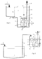
- the clarifier 1 is provided with an inlet 2 for the filter backwashing water and has a storage zone 3 and a settling area 4 or a sludge collecting area 5.
- the storage zone 3 is dimensioned so large that it can accommodate the entire amount of filter backwashing water from a backwashing process of the filter system.
- the clarifier 1 is provided in the sludge collecting area 5 with an outlet for removing sludge.
- the clarifier 1 shown in FIG. 1 has a sludge collecting area 5 of such a height that a plurality of modules of a membrane filter 8 are arranged in the sludge collecting area 5.
- the membranes of the membrane filter 8 are immersed in the medium to be treated, a minimum height of the medium of about 0.3 m being maintained above the membranes.
- the modules 7 of the membrane filter 8 are arranged in a housing 9, in the lower part of which there is an air distributor 10 which is provided with an air supply 11. The rising air creates a flow of the medium along the membranes.
- a permeate line 12 is connected to each membrane and leads to a collecting line 13.
- the collecting line 13 is connected to a discharge line 14 in which a suction pump 15 is arranged.
- the filter backwash water is broken down into clear water and concentrate.
- the filter backwashing water of the storage zone 3 above the membrane filter 8 is completely removed to a minimum filling level in the time between two washing cycles of the filter system.
- the concentrate is increasingly concentrated.
- the concentrate is further treated biologically, depending on its nature, by aerobic sludge stabilization.
- the concentrate is removed as thickened sludge through the outlet.
- the sludge should be disposed of or given a post-treatment.
- the clear water obtained is also free of solids. It can be used immediately and added to the pure water obtained in the filter system. It can also be used as filter backwashing water after temporary storage. If such use is not possible for operational reasons, the clear water can also be mixed in before the filter system or the raw water. The discharge into the receiving water can be done without hesitation.
- the clarifier 1 shown in Fig. 1 is preferably used for new plants. If an existing clarifier 1 does not offer sufficient height to accommodate the immersed membrane filter 8, it is still sufficient Having storage capacity to hold all of the filter backwash water between two wash cycles, the embodiment according to FIG. 2 is selected.
- the membrane filter 8 is housed in a separate container 16. This container 16 is connected to the clarifier 1 via a line 17 which starts from the settling area 4 of the clarifier 1. The outlet for the sludge is provided on the separate container 16. Otherwise, the membrane filter 8 is constructed in the same way as described in connection with the clarifier 1 according to FIG. 1.
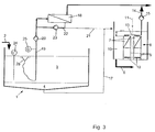
- a water drain 28 floats on the water surface, which is connected to the line via a hose 19 is connected. In this way, on the one hand, the sedimentation process in the clarifier is disturbed as little as possible, and on the other hand, the part of the filter backwashing water which is most freed from solids is fed to the membrane filter unit 18.
- the concentrate-side outlet of the membrane filter unit 18 is connected via a concentrate line 21 to the container 16 receiving the immersed membrane filter 8, which in turn is connected to the clarifier 1 via line 17 connected is.
- the permeate-side outlet of the membrane filter unit 18 is connected to the discharge line 14 coming from the membrane filter 8 and carrying clear water.
- a circulation line 22 is returned from the concentrate line 21 to the inlet of the membrane filter unit 18.
- a circulation pump 23 is arranged in the circulation line 22.
- the pump 20 and the circulation pump 23 can be controlled via sensors which respond to the quality of the filter backwashing water to be treated and the level of the clarification tank 1.
- a level probe 24 can thus protrude into the clarifier 1.
- a sensor 25 can be arranged in the line 19 leading to the membrane filter unit 18, which sensor determines the turbidity, the redox potential or the zeta potential of the aspirated liquid.
- a timer can be provided and a volume flow meter can be provided in the line 19 leading to the membrane filter unit 18.
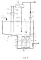
- FIG. 4 differs from that of FIG. 3 in that the circulation line 22 and the circulation pump 23 are replaced by a second line 26 with a second pump 27, and in that the concentrate line 21 into the clarification tank 1 is led.
- a submerged membrane filter 8 is arranged in the clarifier 1.
- the combined arrangement of the immersed membrane filter 8 and the separate membrane filter unit 18 is advantageously used when the sedimentation behavior in the clarifier is not constant or cannot be predicted.
- the immersed membrane filter 8 is used in this combination for the preparation and concentration of the sediment.
- the separate membrane filter unit 18 serves as a high-performance membrane stage for the quick and efficient cleaning of the clear water phase after a short sedimentation time, or depending on the turbidity of the clear water phase.
- the system is controlled on the one hand with the aid of the fill level in the clarifier 1, which decides on the operation of the membrane filter unit 18 and switches off the thickening stage with the immersed membrane filter 8 at a minimal level.
- the system can also be controlled by measuring the turbidity, the solids content, the redox potential, the zeta potential or the like, which decides whether the membrane filter unit 18 is operated in dead-end mode or in cross-flow mode.
- the thickening stage can be started immediately when a minimum level in the storage container is exceeded.
- the membrane filter unit 18 After a short sedimentation time, the membrane filter unit 18 starts operating, which takes place in the dead-end mode up to a certain limit value of the water load and periodically cleans the membranes, the desludged concentrate being fed into the thickening stage. If the turbidity increases in the clear water phase and a preset minimum fill level has not yet been reached, the membrane filter unit 18 can switch over to cross-flow operation. In this case, the circulation pump 22 is switched on, which generates a high overflow speed along the membranes of the membrane filter unit 18 and keeps them at a high performance level even with a higher solids load. The blowdown of thickened contaminants that occurs here also takes place in the thickening stage. It is also possible to purge in the large circulation in the clarifier 1 (Fig. 4) As soon as a minimum fill level in the clarifier 1 is reached, the membrane filter unit 18 switches off and only the thickening stage will process the clarifier 1 to the absolute lowest level, and then also switch off.
Abstract
Description
Die Erfindung betrifft ein Verfahren und eine Vorrichtung zur Aufbereitung von Filterrückspülwasser aus Filteranlagen zur Reinigung von Trinkwasser oder Abwasser nach dem Oberbegriff der Ansprüche 1 und 8.The invention relates to a method and a device for treating filter backwashing water from filter systems for cleaning drinking water or waste water according to the preamble of
Je nach Aufbereitungsverfahren und Rohwasserbeschaffenheit entspricht die Menge des Filterrückspülwassers ca. 0,5 - 6 % der zu filternden Wassermenge. Die Inhaltsstoffe reichen von organischer und anorganischer Belastung durch z.B. Algen und Phosphat bei Oberflächenwasser oder Klärschlamm bei der Filtration von Kläranlagenablauf über Eisen und Mangan bei der Aufbereitung von Grundwässern bis hin zu Arsen, welches in der Trinkwasseraufbereitung ebenfalls aus dem Rohwasser zu entfernen ist.Depending on the treatment method and the nature of the raw water, the amount of filter backwashing water corresponds to approx. 0.5 - 6% of the amount of water to be filtered. The ingredients range from organic and inorganic pollution from e.g. Algae and phosphate in surface water or sewage sludge in the filtration of sewage treatment plants, iron and manganese in the treatment of groundwater and arsenic, which must also be removed from the raw water in drinking water treatment.
Aus der US-PS 37 92 773 ist ein Verfahren zum Rückspülen einer Filtereinheit bekannt, bei dem das Filterrückspülwasser der Klarphase der Filtereinheit entnommen wird. Das bei der Rückspülung der Filtereinheit anfallende, die Filterrückstände enthaltende Filterrückspülwasser wird einem Sedimentationstank zugeführt. In dem Sedimentationstank wird das Filterrückspülwasser in einen Schlammanteil, der die Filterrückstände enthält, und in eine Klarphase getrennt. Die Klarphase aus dem Sedimentationstank wird in das System vor der Filtereinheit zurückgeführt.From US-PS 37 92 773 a method for backwashing a filter unit is known, in which the filter backwash water is removed from the clear phase of the filter unit. The filter backwashing water that occurs during backwashing of the filter unit and contains the filter residues is fed to a sedimentation tank. In the sedimentation tank, the filter backwashing water is separated into a sludge containing the filter residue and a clear phase. The clear phase from the sedimentation tank is returned to the system in front of the filter unit.
Bei dem aus der DE-OS 30 00 503 bekannten Verfahren zur Rückspülung eines Sand- oder Kohlefilters wird das Filterrückspülwasser in einem Haltetank bereitgehalten. Nach dem Rückspülen des Filters wird das mit den Filterrückständen beladene Filterrückspülwasser zur erneuten Verwendung als Rückspülwasser in einem Rückwaschfilter und einer sich daran anschließenden Nachbehandlungseinrichtung aufbereitet.In the process for backwashing a sand or carbon filter known from DE-OS 30 00 503, the filter backwash water is kept ready in a holding tank. After backwashing the filter, the filter backwash water loaded with the filter residue is used again as Backwash water processed in a backwash filter and a subsequent aftertreatment device.
Im Zusammenhang mit der Behandlung von kommunalem Abwasser mittels Belebtschlamm ist ein Verfahren bekannt (EP-PS 510 328), das einen Behälter verwendet, in dem unterhalb der Wasseroberfläche Filtermembranmodule angeordnet sind, Die Filtermembranmodule werden zur Sauerstoffversorgung des Belebtschlammes mit Sauerstoff von Luft umspült. In den Filtermembranen wird das den Belebtschlamm enthaltende Wasser in flüssige und feste Bestandteile getrennt.In connection with the treatment of municipal wastewater using activated sludge, a process is known (EP-PS 510 328) which uses a container in which filter membrane modules are arranged below the water surface. The filter membrane modules are flushed with air from oxygen to supply the activated sludge with oxygen. The water containing the activated sludge is separated into liquid and solid components in the filter membranes.
Das Klarwasser aus der Nachbehandlung des Filterrückspülwassers kann mit den bekannten Verfahren nicht ohne weiters dem Trinkwasser zufügt werden, da nicht alle Inhaltsstoffe des Filterrückspülwassers zuverlässig über die Sedimentation abgetrennt werden können. Das Klarwasser kann auch nicht ohne weiteres dem Rohwasser zufügt werden, da eine Beeinflussung des Klarwassers durch biologische Vorgänge bei der Sedimentation und Eindickung nicht ausgeschlossen werden kann. Das Klarwasser kann dann nicht als Filterrückspülwasser einsetzt werden, wenn biologische Vorgänge während der Sedimentation auftreten, da diese im Kreislauf geführt werden und zu einer unerwünschten Anreicherung auch von gelösten Schadstoffen führen können. Eine weitergehende Filtration des Klarwassers kann wegen der biologischen Vorgänge dazu führen, daß auch der Klarwasserfilter allmählich biologisch aktiv wird, und damit dessen Filtrat nicht mehr unbedenklich zu verwenden ist. Außerdem würde auch dieser Filter Filterrückspülwasser erzeugen.The clear water from the aftertreatment of the filter backwashing water cannot be easily added to the drinking water with the known methods, since not all ingredients of the filter backwashing water can be reliably separated off via the sedimentation. The clear water cannot be easily added to the raw water either, since the clear water cannot be affected by biological processes during sedimentation and thickening. The clear water can then not be used as filter backwash water if biological processes occur during sedimentation, as these are circulated and can lead to an undesired accumulation of dissolved pollutants. Due to the biological processes, further filtration of the clear water can lead to the clear water filter gradually becoming biologically active, so that its filtrate can no longer be used safely. This filter would also produce filter backwash water.
Die Entsorgung des Dünnschlammes, der bei der Sedimentation entsteht, kann zum Teil über die Kläranlage erfolgen. Dort wo dies nicht möglich ist, muß eine Schlammbehandlung durchgeführt werden, die in der statischen Eindickung des Dünnschlammes und eventuell auch einer mechanischen Schlammbehandlung mittels Filterpressen oder Dekanter besteht. Die statische Eindickung erfordert speziell konstruierte Behälter mit großen Tiefen, evtl. Einsatz von Krählwerken zur mechanischen Eindickung und entsprechende Aufenthaltszeiten. Zusätzlich dazu, daß die statische Eindickung je nach abgetrenntem Wasserinhaltsstoff nur unzureichend funktioniert, kann eine lange Aufenthaltszeit des Schlammes zu unkontrollierten biologischen Vorgängen im Bereich der Schlammeindick- und -speicherzone führen. Dieses wird eine Wiederverwendung der Klarwasserphase erschweren. Auch dort, wo die Absetzung augenscheinlich gut funktioniert, ist immer noch ein hoher Anteil an kolloiddispersen Bestandteilen in der Klarwasserphase zu finden, der ebenfalls eine Wiederverwendung einschränken kann.The thin sludge, which arises during sedimentation, can be partially disposed of via the sewage treatment plant. Where this is not possible, a sludge treatment must be carried out using static thickening of the thin sludge and possibly also mechanical sludge treatment Filter presses or decanters exist. Static thickening requires specially designed tanks with great depths, possibly the use of crutters for mechanical thickening and the corresponding dwell times. In addition to the fact that the static thickening only works insufficiently depending on the separated water content, a long residence time of the sludge can lead to uncontrolled biological processes in the area of the sludge thickening and storage zone. This will make it difficult to reuse the clear water phase. Even where the settling apparently works well, there is still a high proportion of colloid-dispersed constituents in the clear water phase, which can also limit reuse.
Die statische Eindickung erreicht bisweilen keine sehr hohen Trockensubstanzgehalte im Schlamm. Infolgedessen werden entweder die Behälter sehr groß oder die zu entsorgende Dünnschlammmenge bleibt hoch. Die Nachteile langer Verweilzeiten sind bereits genannt. Die Entsorgungskosten für dünnen Schlamm sind bekanntermaßen hoch, auch wenn die Benutzung eines öffentlichen Kanals für den Dünnschlamm zur Verfügung steht. Ist kein Kanalanschluß vorhanden, so bleibt nur die kontinuierliche Abfuhr des Dünnschlammes oder die Speicherung für eine Schlammbehandlung zur Auswahl.The static thickening sometimes does not reach very high dry matter contents in the sludge. As a result, either the containers become very large or the amount of thin sludge to be disposed of remains high. The disadvantages of long residence times have already been mentioned. Disposal costs for thin sludge are known to be high, even if the use of a public channel for the thin sludge is available. If there is no sewer connection, only the continuous removal of the thin sludge or the storage for a sludge treatment is available.
Der Erfindung liegt die Aufgabe zugrunde, die Aufbereitung von Filterrückspülwasser so zu gestalten, daß die zu entsorgende Menge an Wasser und Schlamm gering gehalten werden kann.The invention has for its object to design the treatment of filter backwash water so that the amount of water and sludge to be disposed of can be kept low.
Diese Aufgabe wird bei einem gattungsgemäßen Verfahren erfindungsgemäß durch die kennzeichnenden Merkmale des Anspruches 1 gelöst. Eine Vorrichtung zur Lösung der Aufgabe ist Gegenstand des Anspruches 8. Vorteilhafte Ausgestaltungen sind in den Unteransprüchen angegeben.This object is achieved according to the invention in a generic method by the characterizing features of
Durch den Einsatz der Membranfilter läßt sich aus dem Filterrückspülwasser ein Klarwasser erzeugen, das bakteriologisch einwandfrei ist und somit unbedenklich wieder verwendet werden kann. Gleichzeitig ermöglichen die Membranfilter durch die Aufkonzentration des anfallenden Konzentrats eine Verringerung des zu entsorgenden Dünnschlammvolumens. Dabei kann eine aerobe Schlammstabilisierung durchführt werden, die die abbaubaren Kohlenstoffverbindungen reduziert und eine weitere Verminderung des zu entsorgenden Schlammes bewirkt.By using the membrane filter, clear water can be generated from the filter backwashing water, which is bacteriologically perfect and can therefore be reused without any problems. At the same time, the membrane filter enables the volume of thin sludge to be disposed of to be reduced by concentrating the concentrate. Aerobic sludge stabilization can be carried out, which reduces the degradable carbon compounds and further reduces the sludge to be disposed of.
In vorteilhafter Ausgestaltung der Erfindung kann die aerobe Schlammstabilisierung mit Hilfe der getauchten Mikrofiltrationsmodule erfolgen, da diese mit einen Luft- oder Sauerstoffgasstrom betrieben werden, der im Innern des Moduls für eine Strömung und dadurch für einen Cross-Flow entlang der Membranen sorgt.In an advantageous embodiment of the invention, the aerobic sludge stabilization can be carried out with the aid of the immersed microfiltration modules, since these are operated with an air or oxygen gas flow which ensures a flow in the interior of the module and therefore cross-flow along the membranes.
Durch Kombination verschiedener Membranmodule kann die Möglichkeit geschaffen werden, das gesamte Filterrückspülwasser aufzubereiten und zurückzugewinnen. Hierbei werden Mikrofiltrations- oder Ultrafiltrationsanlagen eingeschaltet, die das zunächst dünne gespeicherte Filterrückspülwasser im Dead-End Modus aufkonzentrieren. Gleichzeitig erfolgt eine Eindickung mit Hilfe von anders betriebenen Membransystemen wie z.B. den getauchten Mikrofiltrationsmembranen oder über im Cross-Flow betriebenen nicht getauchte Membrananlagen.By combining different membrane modules, it is possible to treat and recover all of the filter backwash water. Here, microfiltration or ultrafiltration systems are switched on, which concentrate the initially stored filter backwashing water in dead-end mode. At the same time, thickening takes place with the help of membrane systems operated differently, e.g. the immersed microfiltration membranes or via cross-flow non-immersed membrane systems.
Mehrere Ausführungsbeispiele sind in der Zeichnung dargestellt und werden im folgenden näher erläutert. Es zeigen:
- Fig. 1
- schematisch einen Querschnitt durch einen Klärbehälter zur Behandlung von Filterrückspülwasser,
- Fig. 2 bis 5
- ebenfalls schematisch den Querschnitt durch verschiedene Ausführungsformen eines Klärbehälters zur Behandlung von Filterrückspülwasser.
- Fig. 1
- schematically shows a cross section through a clarifier for the treatment of filter backwash water,
- 2 to 5
- also schematically shows the cross section through various embodiments of a clarifier for the treatment of filter backwash water.
In einer nicht gezeigten Filteranlage wird Trink- oder Abwasser gereinigt. Diese Filteranlage wird zur Regeneration der Filter periodisch mit Filterrückspülwasser gespült. Das Filterrückspülwasser nimmt dabei die in der Filteranlage abgetrennten Filterrückstände auf. Das mit den Filterrückständen beladene Filterrückspülwasser wird zur Aufbereitung einem Klärbehälter 1 zugeführt.In a filter system, not shown, drinking or waste water is cleaned. This filter system is periodically rinsed with filter backwash water to regenerate the filter. The filter backwash water absorbs the filter residues separated in the filter system. The filter backwashing water loaded with the filter residues is fed to a
Der Klärbehälter 1 ist mit einem Zulauf 2 für das Filterrückspülwasser versehen und weist eine Speicherzone 3 und einen Absetzbereich 4 bzw. einen Schlammsammelbereich 5 auf. Die Speicherzone 3 ist so groß bemessen, daß sie die gesamte Menge des Filterrückspülwassers aus einem Rückspülvorgang der Filteranlage aufnehmen kann. Der Klärbehälter 1 ist im Schlammsammelbereich 5 mit einem Auslaß zur Entnahme von Schlamm versehen.The
Der in Fig. 1 dargestellte Klärbehälter 1 hat einen Schlammsammelbereich 5 von einer solchen Höhe, daß in dem Schlammsammelbereich 5 mehrere Module eines Membranfilters 8 angeordnet sind. Die Membranfilter 8 enthalten Wickel-, Kapillar-, Platten- oder Rohrmodule mit freien Kanalöffnungen von 0,8 bis 6 mm bei einer Filterfeinheit von <= 0,4 µm.The
Die Membranen des Membranfilters 8 sind in das zu behandelnde Medium eingetaucht, wobei oberhalb der Membranen eine Mindesthöhe des Mediums von etwa 0,3 m eingehalten wird. Die Module 7 des Membranfilters 8 sind in einem Gehäuse 9 angeordnet, in dessen unterem Teil ein Luftverteiler 10 sich befindet, der mit einer Luftzuführung 11 versehen ist. Die aufsteigende Luft erzeugt eine Strömung des Mediums entlang den Membranen. An jede Membran ist eine Permeatleitung 12 angeschlossen, die zu einer Sammelleitung 13 geführt sind. Die Sammelleitung 13 ist mit einer Abführleitung 14 verbunden, in der eine Saugpumpe 15 angeordnet ist.The membranes of the
In dem Membranfilter 8 wird das Filterrückspülwasser in Klarwasser und Konzentrat zerlegt. Dabei wird das Filterrückspülwasser der Speicherzone 3 oberhalb des Membranfilters 8 in der Zeit zwischen zwei Spülzyklen der Filteranlage vollständig bis zu einem Mindestfüllstand entfernt. Gleichzeitig wird das anfallende Konzentrat zunehmend aufkonzentriert. Durch das Einblasen der Luft wird das Konzentrat je nach Beschaffenheit noch auf biologischem Wege weiter behandelt, indem eine aerobe Schlammstabilisierung stattfindet. Nach Erreichen der maximalen Konzentration der Trockensubstanz zum Beispiel von 20 bis 40 g/l wird das Konzentrat als eingedickter Schlamm über den Auslaß entfernt. Der Schlamm ist zu entsorgen oder einer Nachbehandlung zuzuführen.In the
Das in dem Membranfilter 8 filtrierte Klarwasser ist im Falle der Mikrofiltration mit einem Trennbereich von <= 0,4 µm bakteriologisch unbedenklich, weil ab einer Trenngrenze von 0,2 µm Bakterien, Keime und Parasiten sicher zurückgehalten werden. Eine Rückhaltung für Viren kann einerseits durch die Adsorption an dem zurückgehaltenen Feststoff und andererseits durch den Einsatz von Ultrafiltrationsmembranen mit einer Trenngrenze von <= 0,1 µm erfolgen. Das gewonnene Klarwasser ist auch feststofffrei. Es kann unmittelbar gebraucht werden und dem in der Filteranlage gewonnenen Reinwasser zugegeben werden. Es kann auch nach einer Zwischenspeicherung als Filterrückspülwasser verwendet werden. Ist eine solche Verwendung aus betrieblichen Gründen nicht möglich, kann das Klarwasser auch vor der Filteranlage oder dem Rohwasser zugemischt werden. Die Ableitung in den Vorfluter kann bedenkenlos erfolgen.The clear water filtered in the
Der in Fig. 1 gezeigte Klärbehälter 1 wird bevorzugt für Neuanlagen eingesetzt. Wenn ein bereits vorhandener Klärbehälter 1 zwar keine genügende Höhe für die Unterbringung der getauchten Membranfilter 8 bietet, aber noch ausreichend Speicherkapazität aufweist, um das gesamte Filterrückspülwasser zwischen zwei Spülzyklen aufzunehmen, wird die Ausführungsform gemäß Fig. 2 gewählt. In diesem Fall ist das Membranfilter 8 in einem getrennten Behälter 16 untergebracht. Dieser Behälter 16 ist mit dem Klärbehälter 1 über eine Leitung 17 verbunden, die von dem Absetzbereich 4 des Klärbehälters 1 ausgeht. Der Auslaß für den Schlamm ist an dem getrennten Behälter 16 vorgesehen. Im übrigen ist das Membranfilter 8 in der gleichen Weise aufgebaut, wie er im Zusammenhang mit dem Klärbehälter 1 gemäß Fig. 1 beschrieben ist.The
Anstelle (Fig.5) oder vorzugsweise in Verbindung (Fig. 3, 4) mit dem beschriebenen getauchten Membranfilter 8 werden separate, nicht getauchte Membranfiltereinheiten eingesetzt. Diese separaten Membranfiltereinheiten enthalten ebenfalls Wickel-, Kapillar-, Platten- oder Rohrmodule mit freien Kanalöffnungen von 0,8 bis 6 mm bei einer Filterfeinheit von <= 0,4 µm. Sie liegen hinter dem Klärbehälter 1 und sind, wenn getauchte Membranfilter 8 eingesetzt sind, diesen vorgeschaltet.Instead of (Fig. 5) or preferably in connection (Fig. 3, 4) with the described immersed
Bei der in Fig. 3 dargestellten Ausführungsform führt eine Leitung 19, in der eine Pumpe 20 angeordnet ist, aus dem Speicherzone 3 des Klärbehälters 1 zu dem Eingang der Membranfiltereinheit 18. Auf der Wasseroberfläche schwimmt ein Wasserabzug 28, der über einen Schlauch mit der Leitung 19 verbunden ist. Auf diese Weise wird einerseits der Sedimentationsvorgung in dem Klärbehälter möglichst wenig gestört, und andererseits wird der Membranfiltereinheit 18 der Teil des Filterrückspülwassers zugeführt, der am weitesten von Feststoffen befreit ist.In the embodiment shown in FIG. 3, a
Der konzentratseitige Ausgang der Membranfiltereinheit 18 ist über eine Konzentratleitung 21 mit dem die getauchten Membranfilter 8 aufnehmenden Behälter 16 verbunden, der seinerseits über die Leitung 17 mit dem Klärbehälter 1 verbunden ist. Der permeatseitige Ausgang der Membranfiltereinheit 18 ist mit der von dem Membranfilter 8 kommenden das Klarwasser führenden Abführleitung 14 verbunden. Von der Konzentratleitung 21 ist eine Umwälzleitung 22 zu dem Eingang der Membranfiltereinheit 18 zurückgeführt. In der Umwälzleitung 22 ist eine Umwälzpumpe 23 angeordnet.The concentrate-side outlet of the
Die Pumpe 20 und die Umwälzpumpe 23 sind über Meßfühler ansteuerbar, die auf die Qualität des zu behandelnden Filterückspülwassers und den Füllstand des Klärbehälters 1 ansprechen. So kann eine Füllstandstandssonde 24 in den Klärbehälter 1 hineinragen. In der zu der Membranfiltereinheit 18 führenden Leitung 19 kann ein Meßfühler 25 angeordnet sein, der die Trübung, das Redoxpotential oder das Zetapotential der angesaugten Flüssigkeit bestimmt. Ferner kann eine Zeitschaltuhr vorhanden und in der zu der Membranfiltereinheit 18 führenden Leitung 19 ein Volumenstrommesser vorgesehen sein.The
Die in der Fig. 4 dargestellten Ausführungsform unterscheidet sich von der nach Fig. 3 dadurch, daß die Umwälzleitung 22 und die Umwälzpumpe 23 durch eine zweite Leitung 26 mit einer zweiten Pumpe 27 ersetzt sind, und dadurch, daß die Konzentratleitung 21 in den Klärbehälter 1 geführt ist. In dem Klärbehälter 1 ist ein getauchtes Membranfilter 8 angeordnet.The embodiment shown in FIG. 4 differs from that of FIG. 3 in that the
Die kombinierte Anordnung des getauchten Membranfilters 8 und der separaten Membranfiltereinheit 18 wird vorteilhafterweise dann verwendet, wenn das Sedimentationsverhalten im Klärbecken nicht konstant oder nicht vorhersagbar ist. Das getauchte Membranfilter 8 wird bei dieser Kombination zur Aufbereitung und Aufkonzentrierung des Sedimentes verwendet. Die separate Membranfiltereinheit 18 dient als Hochleistungsmembranstufe zur schnellen und effizienten Reinigung der Klarwasserphase nach kurzer Sedimentationszeit, bzw. in Abhängigkeit von der vorhandenen Trübung der Klarwasserphase.The combined arrangement of the immersed
Die Steuerung der Anlage erfolgt einerseits mit Hilfe des Füllstandes in dem Klärbehälter 1, der über den Betrieb der Membranfiltereinheit 18 entscheidet und die Eindickstufe mit dem getauchten Membranfilter 8 bei minimalem Niveau abschaltet. Andererseits kann die Steuerung der Anlage zusätzlich über eine Messung der Trübung, des Feststoffgehaltes, des Redoxpotentiales, des Zetapotentiales o. ä. erfolgen, die entscheidet, ob die Membranfiltereinheit 18 im Dead-End Modus oder im Cross-Flow Betrieb gefahren wird. Die Eindickstufe kann sofort mit Überschreiten eines minimalen Niveaus im Speicherbehälter gestartet werden. Nach kurzer Sedimentationszeit nimmt die Membranfiltereinheit 18 ihren Betrieb auf, der bis zu einem bestimmten Grenzwert der Wasserbelastung im Dead-End Modus erfolgt und periodisch die Membranen abreinigt, wobei das abgeschlämmte Konzentrat in die Eindickstufe gefahren wird. Steigt die Trübung in der Klarwasserphase an, und ist ein voreingestellter minimaler Füllstand noch nicht erreicht, so kann die Membranfiltereinheit 18 auf den Cross-Flow Betrieb umschalten. In diesem Fall wird die Umwälzpumpe 22 zugeschaltet, die eine hohe Überströmgeschwindigkeit entlang der Membranen der Membranfiltereinheit 18 erzeugt und diese auch bei höherer Feststoffbelastung auf einem hohen Leistungsniveau hält. Die hier erfolgende Abschlämmung eingedickter Schmutzstoffe erfolgt ebenfalls in die Eindickstufe hinein. Es ist auch möglich im großen Kreislauf in den Klärbehälter 1 abzuschlämmen (Fig. 4) Sobald ein Mindestfüllstand in dem Klärbehälter 1 erreicht ist, schaltet die Membranfiltereinheit 18 ab und allein die Eindickstufe wird den Klärbehälter 1 bis zum absolut niedrigsten Niveau abarbeiten, um dann ebenfalls abzuschalten.The system is controlled on the one hand with the aid of the fill level in the
Claims (14)
Applications Claiming Priority (2)
| Application Number | Priority Date | Filing Date | Title |
|---|---|---|---|
| DE19616763 | 1996-04-26 | ||
| DE19616763A DE19616763A1 (en) | 1996-04-26 | 1996-04-26 | Method and device for treating filter backwash water |
Publications (2)
| Publication Number | Publication Date |
|---|---|
| EP0803274A1 true EP0803274A1 (en) | 1997-10-29 |
| EP0803274B1 EP0803274B1 (en) | 2003-09-24 |
Family
ID=7792561
Family Applications (1)
| Application Number | Title | Priority Date | Filing Date |
|---|---|---|---|
| EP96119824A Expired - Lifetime EP0803274B1 (en) | 1996-04-26 | 1996-12-11 | Process and apparatus for treatment of backwash water from a filter |
Country Status (3)
| Country | Link |
|---|---|
| EP (1) | EP0803274B1 (en) |
| DE (2) | DE19616763A1 (en) |
| ES (1) | ES2204991T3 (en) |
Cited By (14)
| Publication number | Priority date | Publication date | Assignee | Title |
|---|---|---|---|---|
| EP0941967A2 (en) * | 1998-03-11 | 1999-09-15 | WABAG Wassertechnische Anlagen GmbH | Process for treatment of used of backwash water |
| EP0980699A1 (en) * | 1998-05-29 | 2000-02-23 | Ona Electro-Erosion, S.A. | Plant for cleaning or recovering liquids with suspended particles |
| US7981301B2 (en) * | 2008-11-21 | 2011-07-19 | Scott W. Powell | Method and apparatus for treatment of contaminated liquid |
| US7981293B2 (en) | 2008-11-21 | 2011-07-19 | Scott W. Powell | Method and apparatus for treatment of contaminated liquid |
| US7998225B2 (en) | 2007-02-22 | 2011-08-16 | Powell Scott W | Methods of purifying biodiesel fuels |
| US8048279B2 (en) | 1998-02-27 | 2011-11-01 | Scott Wade Powell | Method and apparatus for electrocoagulation of liquids |
| US8133382B2 (en) | 1998-02-27 | 2012-03-13 | Scott Powell | Method for electrocoagulation of liquids |
| CN103920333A (en) * | 2014-05-07 | 2014-07-16 | 珠江流域水环境监测中心 | Filtering device of toxic organic contaminated water |
| CN105457394A (en) * | 2016-01-12 | 2016-04-06 | 南通联发印染有限公司 | Water recovery system for pre-shrinking machines |
| CN106267934A (en) * | 2016-10-31 | 2017-01-04 | 沈阳建筑大学 | High molecular polymer is regenerating unit and the method that filter aid causes blocking filtrate |
| EP3338877A1 (en) * | 2016-12-22 | 2018-06-27 | Strecker Wassertechnik GmbH | Method and device for filtering a raw fluid containing contamination by means of at least one membrane filter unit and use thereof |
| US10358361B2 (en) | 2013-02-22 | 2019-07-23 | Loren L. Losh | System and method for remediation of wastewater including aerobic and electrocoagulation treatment |
| US10745299B2 (en) | 2013-02-22 | 2020-08-18 | NiBru Traka, Inc. | Struvite formation by precipitation of ammonia in electrocoagulation process |
| CN112452028A (en) * | 2020-10-26 | 2021-03-09 | 上海同臣环保有限公司 | Method capable of simultaneously solving problems of filter cloth blockage and water loss of vertical filter cloth filter |
Families Citing this family (1)
| Publication number | Priority date | Publication date | Assignee | Title |
|---|---|---|---|---|
| DE102005036364B4 (en) * | 2005-07-29 | 2009-04-16 | Aggerverband, Körperschaft Öffentlichen Rechts | Device for extracting process water |
Citations (10)
| Publication number | Priority date | Publication date | Assignee | Title |
|---|---|---|---|---|
| US3792773A (en) | 1971-09-30 | 1974-02-19 | Hydro Clear Corp | Apparatus and method for treating waste liquid |
| JPS541271A (en) * | 1977-06-06 | 1979-01-08 | Ise Chem Ind | Sludge concentration apparatus |
| DE3000503A1 (en) | 1980-01-08 | 1981-07-09 | Pepsico Inc., Purchase, N.Y. | Recycling backwashing effluent from filters - in beverage and bottling plants, for further use following filtering, in adjustment and re-chlorination |
| WO1988003829A1 (en) * | 1986-11-24 | 1988-06-02 | Alfa-Laval Food Engineering Ab | Arrangement in membrane filter |
| WO1991005601A1 (en) * | 1989-10-12 | 1991-05-02 | Ceramesh Limited | Porous inorganic membranes |
| EP0510328A2 (en) | 1991-03-07 | 1992-10-28 | Kubota Corporation | Apparatus for treating activated sludge |
| EP0537516A1 (en) * | 1991-10-05 | 1993-04-21 | Dürr GmbH | Process for treating back-wash liquid from a back-wash filter and sedimentation device for cleaning liquids |
| US5248424A (en) * | 1990-08-17 | 1993-09-28 | Zenon Environmental Inc. | Frameless array of hollow fiber membranes and method of maintaining clean fiber surfaces while filtering a substrate to withdraw a permeate |
| GB2272171A (en) * | 1992-11-10 | 1994-05-11 | Vickers Shipbuilding & Eng | Treatment of effluents |
| EP0662341A1 (en) * | 1994-01-07 | 1995-07-12 | Kubota Corporation | Filtration membrane module |
Family Cites Families (6)
| Publication number | Priority date | Publication date | Assignee | Title |
|---|---|---|---|---|
| FR2313325A1 (en) * | 1975-06-05 | 1976-12-31 | Creusot Loire | PROCESS AND EQUIPMENT FOR TREATING AN EFFLUENT POLLUTED BY COLLOIDAL EMULSIONS |
| DE3800613C2 (en) * | 1988-01-12 | 1997-07-03 | Klein Hans Ulrich Dipl Ing | Method and device for treating water or purifying waste water |
| DD280471A1 (en) * | 1989-03-14 | 1990-07-11 | Koethen Ing Hochschule | PROCESS FOR FILTRATION OF POLLUTED FLUIDS AND FOR REGENERATING THE FILTER USED |
| DE9206238U1 (en) * | 1992-03-25 | 1992-11-12 | Guetling Gmbh, 7012 Fellbach, De | |
| DE9203968U1 (en) * | 1992-03-25 | 1992-05-14 | Guetling Gmbh, 7012 Fellbach, De | |
| GB2291417B (en) * | 1994-07-18 | 1998-05-13 | Wrc Plc | Activated sludge process |
-
1996
- 1996-04-26 DE DE19616763A patent/DE19616763A1/en not_active Withdrawn
- 1996-12-11 DE DE59610737T patent/DE59610737D1/en not_active Expired - Lifetime
- 1996-12-11 ES ES96119824T patent/ES2204991T3/en not_active Expired - Lifetime
- 1996-12-11 EP EP96119824A patent/EP0803274B1/en not_active Expired - Lifetime
Patent Citations (10)
| Publication number | Priority date | Publication date | Assignee | Title |
|---|---|---|---|---|
| US3792773A (en) | 1971-09-30 | 1974-02-19 | Hydro Clear Corp | Apparatus and method for treating waste liquid |
| JPS541271A (en) * | 1977-06-06 | 1979-01-08 | Ise Chem Ind | Sludge concentration apparatus |
| DE3000503A1 (en) | 1980-01-08 | 1981-07-09 | Pepsico Inc., Purchase, N.Y. | Recycling backwashing effluent from filters - in beverage and bottling plants, for further use following filtering, in adjustment and re-chlorination |
| WO1988003829A1 (en) * | 1986-11-24 | 1988-06-02 | Alfa-Laval Food Engineering Ab | Arrangement in membrane filter |
| WO1991005601A1 (en) * | 1989-10-12 | 1991-05-02 | Ceramesh Limited | Porous inorganic membranes |
| US5248424A (en) * | 1990-08-17 | 1993-09-28 | Zenon Environmental Inc. | Frameless array of hollow fiber membranes and method of maintaining clean fiber surfaces while filtering a substrate to withdraw a permeate |
| EP0510328A2 (en) | 1991-03-07 | 1992-10-28 | Kubota Corporation | Apparatus for treating activated sludge |
| EP0537516A1 (en) * | 1991-10-05 | 1993-04-21 | Dürr GmbH | Process for treating back-wash liquid from a back-wash filter and sedimentation device for cleaning liquids |
| GB2272171A (en) * | 1992-11-10 | 1994-05-11 | Vickers Shipbuilding & Eng | Treatment of effluents |
| EP0662341A1 (en) * | 1994-01-07 | 1995-07-12 | Kubota Corporation | Filtration membrane module |
Non-Patent Citations (2)
| Title |
|---|
| DATABASE WPI Week 7907, Derwent World Patents Index; AN 79-12710B, XP002037422 * |
| LEVY P.F. , EARLE R.S.: "The effect of channel height and spacers on flux and energy requirements in crossflow filtration", JOURNAL OF MEMBRANE SCIENCE, vol. 91, no. 1/2, 20 May 1994 (1994-05-20), AMSTERDAM NL, pages 135 - 143, XP000490086 * |
Cited By (18)
| Publication number | Priority date | Publication date | Assignee | Title |
|---|---|---|---|---|
| US8048279B2 (en) | 1998-02-27 | 2011-11-01 | Scott Wade Powell | Method and apparatus for electrocoagulation of liquids |
| US8133382B2 (en) | 1998-02-27 | 2012-03-13 | Scott Powell | Method for electrocoagulation of liquids |
| EP0941967A3 (en) * | 1998-03-11 | 2002-05-15 | WABAG Wassertechnische Anlagen GmbH | Process for treatment of used of backwash water |
| EP0941967A2 (en) * | 1998-03-11 | 1999-09-15 | WABAG Wassertechnische Anlagen GmbH | Process for treatment of used of backwash water |
| EP0980699A1 (en) * | 1998-05-29 | 2000-02-23 | Ona Electro-Erosion, S.A. | Plant for cleaning or recovering liquids with suspended particles |
| US7998225B2 (en) | 2007-02-22 | 2011-08-16 | Powell Scott W | Methods of purifying biodiesel fuels |
| US8192617B2 (en) | 2008-11-21 | 2012-06-05 | Powell Scott W | System for treatment of contaminated liquid |
| US7981293B2 (en) | 2008-11-21 | 2011-07-19 | Scott W. Powell | Method and apparatus for treatment of contaminated liquid |
| US7981301B2 (en) * | 2008-11-21 | 2011-07-19 | Scott W. Powell | Method and apparatus for treatment of contaminated liquid |
| US10358361B2 (en) | 2013-02-22 | 2019-07-23 | Loren L. Losh | System and method for remediation of wastewater including aerobic and electrocoagulation treatment |
| US10745299B2 (en) | 2013-02-22 | 2020-08-18 | NiBru Traka, Inc. | Struvite formation by precipitation of ammonia in electrocoagulation process |
| US11407660B2 (en) | 2013-02-22 | 2022-08-09 | Bio2 Pw Inc. | System and method for remediation of wastewater including aerobic and electrocoagulation treatment |
| CN103920333A (en) * | 2014-05-07 | 2014-07-16 | 珠江流域水环境监测中心 | Filtering device of toxic organic contaminated water |
| CN103920333B (en) * | 2014-05-07 | 2016-02-17 | 珠江流域水环境监测中心 | The filter of poisonous organic pollution water body |
| CN105457394A (en) * | 2016-01-12 | 2016-04-06 | 南通联发印染有限公司 | Water recovery system for pre-shrinking machines |
| CN106267934A (en) * | 2016-10-31 | 2017-01-04 | 沈阳建筑大学 | High molecular polymer is regenerating unit and the method that filter aid causes blocking filtrate |
| EP3338877A1 (en) * | 2016-12-22 | 2018-06-27 | Strecker Wassertechnik GmbH | Method and device for filtering a raw fluid containing contamination by means of at least one membrane filter unit and use thereof |
| CN112452028A (en) * | 2020-10-26 | 2021-03-09 | 上海同臣环保有限公司 | Method capable of simultaneously solving problems of filter cloth blockage and water loss of vertical filter cloth filter |
Also Published As
| Publication number | Publication date |
|---|---|
| DE59610737D1 (en) | 2003-10-30 |
| DE19616763A1 (en) | 1997-11-06 |
| ES2204991T3 (en) | 2004-05-01 |
| EP0803274B1 (en) | 2003-09-24 |
Similar Documents
| Publication | Publication Date | Title |
|---|---|---|
| DE60104188T2 (en) | METHOD AND DEVICE FOR TREATING WATER / WASTEWATER | |
| DE4445682C2 (en) | Process for cleaning a separator with a submerged ceramic filter | |
| EP0503649B1 (en) | Process and apparatus for biological purification of waste waters polluted with non biodegradable or hardly biodegradable substances | |
| EP0803274B1 (en) | Process and apparatus for treatment of backwash water from a filter | |
| DE4325335A1 (en) | Fluid treatment process using dynamic microfiltration and ultrafiltration | |
| DE19630089C1 (en) | Process and assembly treats waste water and tensides separately by nano-filtration | |
| EP1568662B1 (en) | Membrane bioreactor and method for wastewater treatment | |
| EP0806399A1 (en) | Process and device for purifying waste water | |
| EP1832333A1 (en) | Method for recovery of impure fluids | |
| EP1041044B1 (en) | A method of purifying waste water containing phenolics | |
| DE4415637A1 (en) | Clarification and purification of vehicle wash water for recycling | |
| KR0162157B1 (en) | Process for treating chemical waste by reverse osmotic membrane system | |
| DE19810388B4 (en) | Process for the treatment of spent backwash water | |
| EP1294647A1 (en) | Method and device for purifying and treating waste water in order to obtain drinking water | |
| AT519319B1 (en) | Treatment of wastewater into drinking water using ozone | |
| AT393497B (en) | METHOD FOR TREATING WASTEWATER | |
| EP1265819B1 (en) | Method and device for effluent treatment | |
| DE102005055146A1 (en) | Cyclic procedure for processing bath water from swimming pool, includes filtering a part of a circulating bath water quantity by membrane filter and particle filtering of another part of the circulating water quantity supplied into bypass | |
| EP0567914A1 (en) | Process and apparatus for waste water purification | |
| EP1767499B1 (en) | Method and installation for service water treatment | |
| WO2003076346A2 (en) | Circulation method and system for treating bathing water | |
| JPH074598B2 (en) | Human waste system treatment equipment | |
| EP0567866A1 (en) | Treating of waste water from printing plants | |
| DE2753216A1 (en) | PROCESS AND DEVICE FOR SEPARATING POLLUTANTS THAT SOLVED IN WASHING SOLUTIONS | |
| DE10105221A1 (en) | Small-scale waste water treatment assembly pump discharges through a ceramic filter |
Legal Events
| Date | Code | Title | Description |
|---|---|---|---|
| PUAI | Public reference made under article 153(3) epc to a published international application that has entered the european phase |
Free format text: ORIGINAL CODE: 0009012 |
|
| AK | Designated contracting states |
Kind code of ref document: A1 Designated state(s): BE DE ES FR GB IT PT |
|
| 17P | Request for examination filed |
Effective date: 19971105 |
|
| 17Q | First examination report despatched |
Effective date: 20001214 |
|
| GRAH | Despatch of communication of intention to grant a patent |
Free format text: ORIGINAL CODE: EPIDOS IGRA |
|
| RAP1 | Party data changed (applicant data changed or rights of an application transferred) |
Owner name: VA TECH WABAG DEUTSCHLAND GMBH & CO. KG |
|
| GRAH | Despatch of communication of intention to grant a patent |
Free format text: ORIGINAL CODE: EPIDOS IGRA |
|
| RAP1 | Party data changed (applicant data changed or rights of an application transferred) |
Owner name: VA TECH WABAG DEUTSCHLAND GMBH & CO. KG |
|
| GRAS | Grant fee paid |
Free format text: ORIGINAL CODE: EPIDOSNIGR3 |
|
| GRAA | (expected) grant |
Free format text: ORIGINAL CODE: 0009210 |
|
| AK | Designated contracting states |
Kind code of ref document: B1 Designated state(s): BE DE ES FR GB IT PT |
|
| REG | Reference to a national code |
Ref country code: GB Ref legal event code: FG4D Free format text: NOT ENGLISH |
|
| REF | Corresponds to: |
Ref document number: 59610737 Country of ref document: DE Date of ref document: 20031030 Kind code of ref document: P |
|
| PG25 | Lapsed in a contracting state [announced via postgrant information from national office to epo] |
Ref country code: BE Free format text: LAPSE BECAUSE OF NON-PAYMENT OF DUE FEES Effective date: 20031231 |
|
| GBT | Gb: translation of ep patent filed (gb section 77(6)(a)/1977) |
Effective date: 20040107 |
|
| REG | Reference to a national code |
Ref country code: ES Ref legal event code: FG2A Ref document number: 2204991 Country of ref document: ES Kind code of ref document: T3 |
|
| ET | Fr: translation filed | ||
| BERE | Be: lapsed |
Owner name: *VA TECH WABAG DEUTSCHLAND G.M.B.H. & CO. K.G. Effective date: 20031231 |
|
| PLBE | No opposition filed within time limit |
Free format text: ORIGINAL CODE: 0009261 |
|
| STAA | Information on the status of an ep patent application or granted ep patent |
Free format text: STATUS: NO OPPOSITION FILED WITHIN TIME LIMIT |
|
| 26N | No opposition filed |
Effective date: 20040625 |
|
| PG25 | Lapsed in a contracting state [announced via postgrant information from national office to epo] |
Ref country code: PT Free format text: LAPSE BECAUSE OF NON-PAYMENT OF DUE FEES Effective date: 20040224 |
|
| PGFP | Annual fee paid to national office [announced via postgrant information from national office to epo] |
Ref country code: IT Payment date: 20101216 Year of fee payment: 15 Ref country code: GB Payment date: 20101224 Year of fee payment: 15 |
|
| PGFP | Annual fee paid to national office [announced via postgrant information from national office to epo] |
Ref country code: FR Payment date: 20110119 Year of fee payment: 15 |
|
| PGFP | Annual fee paid to national office [announced via postgrant information from national office to epo] |
Ref country code: ES Payment date: 20101220 Year of fee payment: 15 |
|
| GBPC | Gb: european patent ceased through non-payment of renewal fee |
Effective date: 20111211 |
|
| REG | Reference to a national code |
Ref country code: FR Ref legal event code: ST Effective date: 20120831 |
|
| PG25 | Lapsed in a contracting state [announced via postgrant information from national office to epo] |
Ref country code: GB Free format text: LAPSE BECAUSE OF NON-PAYMENT OF DUE FEES Effective date: 20111211 |
|
| PG25 | Lapsed in a contracting state [announced via postgrant information from national office to epo] |
Ref country code: IT Free format text: LAPSE BECAUSE OF NON-PAYMENT OF DUE FEES Effective date: 20111211 |
|
| PG25 | Lapsed in a contracting state [announced via postgrant information from national office to epo] |
Ref country code: FR Free format text: LAPSE BECAUSE OF NON-PAYMENT OF DUE FEES Effective date: 20120102 |
|
| REG | Reference to a national code |
Ref country code: ES Ref legal event code: FD2A Effective date: 20130703 |
|
| PG25 | Lapsed in a contracting state [announced via postgrant information from national office to epo] |
Ref country code: ES Free format text: LAPSE BECAUSE OF NON-PAYMENT OF DUE FEES Effective date: 20111212 |
|
| PGFP | Annual fee paid to national office [announced via postgrant information from national office to epo] |
Ref country code: DE Payment date: 20131231 Year of fee payment: 18 |
|
| REG | Reference to a national code |
Ref country code: DE Ref legal event code: R119 Ref document number: 59610737 Country of ref document: DE |
|
| PG25 | Lapsed in a contracting state [announced via postgrant information from national office to epo] |
Ref country code: DE Free format text: LAPSE BECAUSE OF NON-PAYMENT OF DUE FEES Effective date: 20150701 |