EP0510303B1 - Vibration damping element on a weighing device - Google Patents
Vibration damping element on a weighing device Download PDFInfo
- Publication number
- EP0510303B1 EP0510303B1 EP92101514A EP92101514A EP0510303B1 EP 0510303 B1 EP0510303 B1 EP 0510303B1 EP 92101514 A EP92101514 A EP 92101514A EP 92101514 A EP92101514 A EP 92101514A EP 0510303 B1 EP0510303 B1 EP 0510303B1
- Authority
- EP
- European Patent Office
- Prior art keywords
- vibration damping
- damping element
- element according
- damping
- different heights
- Prior art date
- Legal status (The legal status is an assumption and is not a legal conclusion. Google has not performed a legal analysis and makes no representation as to the accuracy of the status listed.)
- Expired - Lifetime
Links
Images
Classifications
-
- G—PHYSICS
- G01—MEASURING; TESTING
- G01G—WEIGHING
- G01G21/00—Details of weighing apparatus
- G01G21/02—Arrangements of bearings
- G01G21/10—Floating suspensions; Arrangements of shock absorbers
-
- G—PHYSICS
- G01—MEASURING; TESTING
- G01G—WEIGHING
- G01G23/00—Auxiliary devices for weighing apparatus
- G01G23/06—Means for damping oscillations, e.g. of weigh beams
Definitions
- the invention relates to a vibration damping element on a scale.
- Vibration damping elements which decouple the weighing pan from the weighing pan support or the scales or the scale housing from its support or mounting platform, are known, for example, from US Pat. No. 4,489,797.
- the vibration damping element described here consists of an elastic material and is embedded in the weighing pan support up to a part of its total height. It has a blind bore into which a holding element or a load measuring element of the scale housing engages.
- Such a damping element only dampens the vibrations that occur to a very limited extent when an object is placed on the weighing pan.
- such a damping element can influence the vibration behavior of the scale with a load and that without a load very little, because the shape gives almost no possibility for a coordination to the different vibration behavior in these two cases.
- such a damping element cannot be used to achieve an almost uniform natural frequency behavior of the balance for the entire load range can be achieved. However, such is desirable.
- the object of the invention is therefore to avoid the disadvantages of the prior art and to create damping elements which, due to their structure, can be used in a wide variety of ways for the forces and loads occurring on a balance.
- an almost uniform vibration behavior of the balance should be achieved for the entire load range, in particular with regard to its natural frequency.
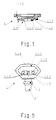
- a vibration damping element 1 has a base plate 1.1.3, which is set up for attachment to a weighing pan support or a housing of a balance, optionally also for snap-in attachment, for example by means of attached pins 2 with clamping elements 2.1 or the like seated thereon.
- damping body 1.1 which are designed as two differently high, combined damping bodies 1st and 2nd type 1.1.1 or 1.1.2, each with its end facing away from the base plate 1.1.3 1.1.4 or 1.1.5 are set up to support the balance on a base or to support a weighing pan on a weighing pan support.
- the power transmission from the scale housing to the base or from a weighing pan or to a weighing pan support is carried out up to a first load level by a 1st damping body 1.1.1 and from this additionally by a 2nd damping body 1.1.2.
- the two damping bodies 1. and 2. Art 1.1.1 and 1.1.2 of the Vibration damping element 1 are designed here as concentrically arranged cylinders or prisms or hollow cylinders or hollow prisms of different heights, the different heights corresponding to the different load levels or loads on the scale.
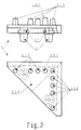
- a second version [Fig. 2] are arranged on the base plate 1.1.3 of the damping body 1.1 next to one another, at least two differently high damping bodies of the 1st and 2nd types 1.1.1 and 1.1.2 being provided, each with its end face 1.1 facing away from the base plate 1.1.3 .4 or 1.1.5 are set up to support the balance on a base or to support a weighing pan on a weighing pan support.
- the force is transmitted from the scale housing to the base or a weighing pan to a weighing pan support up to a first load level by at least one 1st damping body 1.1.1 and from this additionally by at least one 2nd damping body 1.1.2.
- the two damping bodies 1 and 2 types 1.1.1 and 1.1.2, of the vibration damping element 1 are designed as cylinders, prisms, truncated cones or truncated pyramids of different heights, the different heights corresponding to the different load levels or loads on the scales correspond and are intended for this.
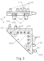
- a third embodiment variant [Fig. 3] are, as in the second variant, on a base surface of the base plate 1.1.3 Damping body 1.1 arranged next to one another, at least two differently high damping bodies of the 1st and / or 2nd type 1.1.1 and 1.1.2 being provided.
- damping bodies of the 1st or 2nd type are also provided on the lateral edges of the base plate 1.1.3, the axis direction of which is arranged substantially perpendicular to the axis direction of the damping body of the 1st or 2nd type arranged on the base surface of the base plate 1.1.3 and to the system Side surfaces of the weighing pan or an installation unit of the scale housing can be brought.
- These damping bodies arranged on the side edges can, like the damping bodies 2nd type 1.1.2, be designed as prisms, cylinders, truncated cones, truncated pyramids, roof prisms etc. or as a combination thereof.
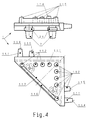
- FIG. 4 A fourth embodiment variant [Fig. 4] corresponds to the variant according to FIG. 3.
- the 1st type 1.1.1 damping body arranged in the acute-angled corners of the basic body are connected to one another by means of a web 1.1.6, which gives the two exposed damping bodies more stability, in particular with respect to forces acting obliquely on them.
- a fifth embodiment variant [Fig. 5] are provided on the base plate 1.1.3 two differently high damping bodies 1st and 2nd type 1.1.1 and 1.1.2, each with their end face 1.1.4 or 1.1.5 facing away from the base plate 1.1.3 are set up for supporting the balance on a base or for supporting a weighing pan on a weighing pan support.
- the power is transmitted from the scale housing to the base or a weighing pan to a weighing pan support in a first load level by a 1st damping body 1st type 1.1.1 in a second form ⁇ diamond shape ⁇ and in a second loading level additionally by a damping body 2nd type 1.1.2 .
- the 1st type 1.1.1 damping body in the 2nd form ⁇ diamond shape ⁇ is connected to the base plate 1.1.3, whereby it has a laterally open, open or closed diamond shape and the damping body 2 Includes Art 1.1.2 in their axial direction overlapping and overhanging.
- the damping body 1.1 in the first form ⁇ prism or cone shape ⁇ can be provided concentrically with one another, next to one another or also in a mixture of these two arrangement possibilities. It is essential that the damping body of the 2nd type 1.1.2 have a lower height than the damping body of the 1st type 1.1.1. A gradual load absorption by the vibration damping element 1 is thereby ensured when the weighing pan is loaded. This causes a gradual change in the vibration behavior of the scale.
- damping bodies 1 and 2 types 1.1.1 and 1.1.2 of the vibration damping element 1 can be provided transversely to their axis for a floating mounting of the scale housing opposite the base or a weighing pan on a weighing pan support.
- vibration damping element 1 can consist of electrically conductive and at the same time rubber-elastic material.
- the vibration damping element 1 can also have damping bodies 1.1.3 on its base plate 1.1.3, which are arranged in different plane directions, in particular those normal to one another, and can thus be brought into contact with further surfaces of a weighing pan or a base of the weighing scale.
- damping body 1.1 1st or 2nd type each with a non-linear spring characteristic, which, in cooperation with the shape of the damping body 1.1, enables an even finer gradation of the vibration behavior of the scale.
- a nonlinear spring characteristic can, as described above, be carried out constructively or through the choice of material.
- rubber has a generally non-linear spring characteristic.
- a suitable combination of shape and material can be used to achieve a still substantial improvement in the adaptation to the desired vibration behavior of the balance in the various load situations.
- Such a multi-stage damping element according to the invention not only determines the vibration behavior, but also improves the behavior in relation to impacts on the scales and makes such impacts largely ineffective with regard to the accuracy of the weighing.
- a 2-stage damping element can take up the normal load of the weighing range in one of the possible design variants in its first, higher stage and the overload in the second, lower stage. This ensures that the first stage is not worn out or damaged in the event of an overload.
- the column-shaped damping bodies have the advantage that they can easily be attached to different types of scales, ie to their different vibration or natural vibration behavior. are customizable.
- damping bodies of the 1st or 2nd type 1.1.1 or 1.1.2 they can be attached to the free end faces 1.1.4 or 1.1.5 at which they come into contact with a third object, for example the footprint of one Libra, etc., be designed convex.
- the variant with the diamond shape of the 1st type damping body in the 2nd form offers the essential advantage that an even better separation of the 2-stage can be achieved by the point of overload at which the 2nd type damping body should come into action can be precisely determined.
Description
Die Erfindung bezieht sich auf ein Vibrationsdaempfungselement, an einer Waage.The invention relates to a vibration damping element on a scale.
Vibrationsdaempfungselemente, welche die Waagschale vom Waagschalentraeger oder die Waage bzw. das Waagengehaeuse von dessen Unterlage oder Einbauplattform daempfend entkoppeln, sind beispielsweise aus der US 44 89 797 bekannt. Das hier beschriebene Vibrationsdaempfungselement besteht aus einem elastischen Material und ist in den Waagschalentraeger bis zu einem Teil seiner Gesamthoehe eingelassen. Es weist eine Sackbohrung auf, in die ein Halteelement oder ein Lastmesselement des Waagengehaeuses eingreift.Vibration damping elements, which decouple the weighing pan from the weighing pan support or the scales or the scale housing from its support or mounting platform, are known, for example, from US Pat. No. 4,489,797. The vibration damping element described here consists of an elastic material and is embedded in the weighing pan support up to a part of its total height. It has a blind bore into which a holding element or a load measuring element of the scale housing engages.
Ein solches Daempfungselement daempft nur in sehr beschraenktem Mass die auftretenden Schwingungen, wenn ein Gegenstand auf die Waagschale gelegt wird. Ausserdem kann ein solches Daempfungselement das Vibrationsverhalten der Waage mit Last und das ohne Last nur sehr wenig beeinflussen, weil durch die Formgebung fast keine Moeglichkeiten fuer eine Abstimmung auf das unterschiedliche Vibrationsverhalten in diesen beiden Faellen gegeben ist. Insbesondere kann mit einem solchen Daempfungselement nicht ein fuer den gesamten Lastbereich nahezu gleichmaessiges Eigenfrequenzverhalten der Waage erreicht werden. Ein solches ist jedoch wuenschenswert.Such a damping element only dampens the vibrations that occur to a very limited extent when an object is placed on the weighing pan. In addition, such a damping element can influence the vibration behavior of the scale with a load and that without a load very little, because the shape gives almost no possibility for a coordination to the different vibration behavior in these two cases. In particular, such a damping element cannot be used to achieve an almost uniform natural frequency behavior of the balance for the entire load range can be achieved. However, such is desirable.
Die Aufgabe der Erfindung ist daher die Vermeidung der Nachteile des Standes der Technik und die Schaffung von Daempfungselementen, welche zufolge ihres Aufbaues in verschiedenster Weise fuer die auftretenden Kraefte und Lastfaelle einer Waage einsetzbar sind. Ausserdem soll ein fuer den gesamten Lastbereich nahezu gleichmaessiges Vibrationsverhalten der Waage erreicht werden, insbesondere hinsichtlich ihrer Eigenfrequenz.The object of the invention is therefore to avoid the disadvantages of the prior art and to create damping elements which, due to their structure, can be used in a wide variety of ways for the forces and loads occurring on a balance. In addition, an almost uniform vibration behavior of the balance should be achieved for the entire load range, in particular with regard to its natural frequency.
Diese Aufgabe wird erfindungsgemaess durch das Kennzeichen des Anspruches 1 geloest. Darueberhinaus koennen solche Vibrationsdaempfungselemente die Merkmale der Ansprueche 2 bis 14 aufweisen. Weitere Einzelheiten und Merkmale erfindungsgemaesser Vibrationsdaempfungselemente ergeben sich aus der Beschreibung von Ausfuehrungsbeispielen anhand der Zeichnung. In dieser zeigt
- Fig. 1
- einen Schnitt durch eine 1. Variante eines Vibrationsdaempfungselementes mit Zylinder oder Prismen {konzentrische Anordnung},
- Fig. 2
- eine 2. Variante eines Vibrationsdaempfungselementes in Seitenansicht und in Draufsicht {benachbarte Anordnung},
- Fig. 3
- eine 3. Variante eines Vibrationsdaempfungselementes in Seitenansicht und in Draufsicht, mit zusaetzlichen, seitlich angeordneten Daempfungselementen,
- Fig. 4
- eine 4. Variante eines Vibrationsdaempfungselementes in Seitenansicht und in Draufsicht, mit zusätzlichen, seitlich angeordneten Daempfungselementen sowie einem Steg zwischen Daempfungselementen der Basisflaeche,
- Fig. 5
- eine 5. Variante eines Vibrationsdaempfungselementes {Rautenform} in Seitenansicht.
- Fig. 1
- a section through a 1st variant of a vibration damping element with cylinder or prisms {concentric arrangement},
- Fig. 2
- a second variant of a vibration damping element in side view and in plan view {adjacent arrangement},
- Fig. 3
- a third variant of a vibration damping element in side view and in plan view, with additional, laterally arranged damping elements,
- Fig. 4
- a fourth variant of a vibration damping element in side view and in plan view, with additional, laterally arranged damping elements and a web between damping elements of the base surface,
- Fig. 5
- a 5th variant of a vibration damping element {diamond shape} in side view.
Ein Vibrationsdaempfungselement 1 weist eine Grundplatte 1.1.3 auf, welche zum Anbau an einen Waagschalentraeger oder ein Gehaeuse einer Waage, gegebenenfalls auch zum einrastenden Anbau, beispielsweise durch aufgesetzte Zapfen 2 mit auf diesen sitzenden Klemmelementen 2.1 odgl., eingerichtet ist.A vibration damping element 1 has a base plate 1.1.3, which is set up for attachment to a weighing pan support or a housing of a balance, optionally also for snap-in attachment, for example by means of attached
Bei einer 1. Ausfuehrungsvariante [Fig. 1] sind auf der Grundplatte 1.1.3 Daempfungskoerper 1.1 vorgesehen, welche als zwei verschieden hohe, kombinierte Daempfungskoerper 1. und 2. Art 1.1.1 bzw. 1.1.2 ausgebildet sind, die je mit ihrer von der Grundplatte 1.1.3 abgewandten Stirnseite 1.1.4 bzw. 1.1.5 zum Abstuetzen der Waage auf einer Unterlage oder zum Abstuetzen einer Waagschale auf einem Waagschalentraeger eingerichtet sind. Dabei wird die Kraftuebertragung vom Waagengehaeuse zur Unterlage oder von einer Waagschale oder auf einen Waagschalentraeger bis zu einer ersten Belastungsstufe von einem 1. Daempfungskoerper 1.1.1 und ab dieser zusaetzlich von einem 2. Daempfungskoerper 1.1.2 uebernommen. Die beiden Daempfungskoerper 1. und 2. Art 1.1.1 bzw. 1.1.2 des Vibrationsdaempfungselementes 1 sind hier als konzentrisch angeordnete Zylinder oder Prismen oder Hohlzylinder oder Hohlprismen verschiedener Hoehe ausgebildet, wobei die verschiedenen Hoehen den unterschiedlichen Laststufen bzw. Belastungen der Waage entsprechen.In a 1st embodiment variant [Fig. 1] are provided on the base plate 1.1.3 damping body 1.1, which are designed as two differently high, combined damping bodies 1st and 2nd type 1.1.1 or 1.1.2, each with its end facing away from the base plate 1.1.3 1.1.4 or 1.1.5 are set up to support the balance on a base or to support a weighing pan on a weighing pan support. The power transmission from the scale housing to the base or from a weighing pan or to a weighing pan support is carried out up to a first load level by a 1st damping body 1.1.1 and from this additionally by a 2nd damping body 1.1.2. The two damping bodies 1. and 2. Art 1.1.1 and 1.1.2 of the Vibration damping element 1 are designed here as concentrically arranged cylinders or prisms or hollow cylinders or hollow prisms of different heights, the different heights corresponding to the different load levels or loads on the scale.
Bei einer 2. Ausfuehrungsvariante [Fig. 2] sind auf der Grundplatte 1.1.3 Daempfungskoerper 1.1 nebeneinander angeordnet, wobei wenigstens zwei verschieden hohe Daempfungskoerper 1. und 2. Art 1.1.1 bzw. 1.1.2 vorgesehen sind, welche je mit ihrer von der Grundplatte 1.1.3 abgewandten Stirnseite 1.1.4 bzw. 1.1.5 zum Abstuetzen der Waage auf einer Unterlage oder zum Abstuetzen einer Waagschale auf einem Waagschalentraeger eingerichtet sind. Dabei erfolgt die Kraftuebertragung vom Waagengehaeuse zur Unterlage oder einer Waagschale auf einen Waagschalentraeger bis zu einer ersten Belastungsstufe durch wenigstens einen 1. Daempfungskoerper 1.1.1 und ab dieser zusaetzlich durch wenigstens einen 2. Daempfungskoerper 1.1.2. Die beiden Daempfungskoerper 1. und 2. Art 1.1.1 bzw. 1.1.2 des Vibrationsdaempfungselementes 1 sind in dieser Ausfuehrungsform als nebeneinander angeordnete Zylinder, Prismen, Kegelstumpfe oder Pyramidenstumpfe verschiedener Hoehe ausgebildet, wobei die verschiedenen Hoehen den unterschiedlichen Laststufen bzw. Belastungen der Waage entsprechen und fuer diese vorgesehen sind.In a second version [Fig. 2] are arranged on the base plate 1.1.3 of the damping body 1.1 next to one another, at least two differently high damping bodies of the 1st and 2nd types 1.1.1 and 1.1.2 being provided, each with its end face 1.1 facing away from the base plate 1.1.3 .4 or 1.1.5 are set up to support the balance on a base or to support a weighing pan on a weighing pan support. The force is transmitted from the scale housing to the base or a weighing pan to a weighing pan support up to a first load level by at least one 1st damping body 1.1.1 and from this additionally by at least one 2nd damping body 1.1.2. In this embodiment, the two
Bei einer 3. Ausfuehrungsvariante [Fig. 3] sind wie in der 2. Variante auf einer Basisflaeche der Grundplatte 1.1.3 Daempfungskoerper 1.1 nebeneinander angeordnet, wobei wenigstens zwei verschieden hohe Daempfungskoerper 1. und/oder 2. Art 1.1.1 bzw. 1.1.2 vorgesehen sind. Ausserdem sind an den seitlichen Raendern der Grundplatte 1.1.3 ebenfalls Daempfungskoerper 1. oder 2. Art vorgesehen, deren Achsenrichtung im wesentlichen senkrecht zur Achsenrichtung der auf der Basisflaeche der Grundplatte 1.1.3 angeordneten Daempfungskoerper 1. oder 2. Art angeordnet und zur Anlage an Seitenflaechen der Waagschale oder einer Einbaueinheit des Waagengehaeuses bringbar sind. Auch diese an den Seitenraendern angeordneten Daempfungskoerper koennen, wie die Daempfungkoerper 2. Art 1.1.2, als Prismen, Zylinder, Kegelstumpfe, Pyramidenstumpfe, Dachkantprismen usw. oder als Kombination derselben ausgebildet sein.In a third embodiment variant [Fig. 3] are, as in the second variant, on a base surface of the base plate 1.1.3 Damping body 1.1 arranged next to one another, at least two differently high damping bodies of the 1st and / or 2nd type 1.1.1 and 1.1.2 being provided. In addition, damping bodies of the 1st or 2nd type are also provided on the lateral edges of the base plate 1.1.3, the axis direction of which is arranged substantially perpendicular to the axis direction of the damping body of the 1st or 2nd type arranged on the base surface of the base plate 1.1.3 and to the system Side surfaces of the weighing pan or an installation unit of the scale housing can be brought. These damping bodies arranged on the side edges can, like the damping bodies 2nd type 1.1.2, be designed as prisms, cylinders, truncated cones, truncated pyramids, roof prisms etc. or as a combination thereof.
Eine 4. Ausfuehrungsvariante [Fig. 4] entspricht der Variante nach Figur 3.A fourth embodiment variant [Fig. 4] corresponds to the variant according to FIG. 3.
Darueberhinaus sind jedoch die in den spitzwinkeligen Ecken des Grundkoerpers angeordneten Daempfungskoerper 1. Art 1.1.1 mittels eines Steges 1.1.6 miteinander verbunden, was den beiden exponierten Daempfungskoerpern mehr Stabilitaet verleiht, insbesondere gegenueber schraeg auf sie wirkenden Kraeften.In addition, however, the 1st type 1.1.1 damping body arranged in the acute-angled corners of the basic body are connected to one another by means of a web 1.1.6, which gives the two exposed damping bodies more stability, in particular with respect to forces acting obliquely on them.
Bei einer 5. Ausfuehrungsvariante [Fig. 5] sind auf der Grundplatte 1.1.3 zwei verschieden hohe Daempfungskoerper 1. und 2. Art 1.1.1 bzw. 1.1.2 vorgesehen, welche je mit ihrer von der Grundplatte 1.1.3 abgewandten Stirnseite 1.1.4 bzw. 1.1.5 zum Abstuetzen der Waage auf einer Unterlage oder zum Abstuetzen einer Waagschale auf einem Waagschalentraeger eingerichtet sind. Dabei erfolgt die Kraftuebertragung vom Waagengehaeuse zur Unterlage oder einer Waagschale auf einen Waagschalentraeger in einer ersten Belastungsstufe durch einen 1. Daempfungskoerper 1. Art 1.1.1 in 2. Form {Rautenform} und in einer zweiten Belastungsstufe zusaetzlich durch Daempfungskoerper 2. Art 1.1.2. Dabei sind diese als nebeneinander angeordnete Prismen, Zylinder, Kegelstumpfe, Pyramidenstumpfe, Dachkantprismen usw., also im wesentlichen als saeulenfoermige Koerper, gleicher Hoehe ausgebildet. Im Bereich der seitlichen Raender der Grundplatte 1.1.3 ist der Daempfungskoerper 1. Art 1.1.1 in 2. Form {Rautenform} an die Grundplatte 1.1.3 angeschlossen, wobei er eine seitlich offene, oben offene oder geschlossene Rautenform besitzt und die Daempfungskoerper 2. Art 1.1.2 in deren axialer Richtung uebergreifend und ueberragend einschliesst. Auf der Grundplatte 1.1.3 ist auf der den Daempfungskoerpern abgewandten Seite ein Zapfen 2 mit auf diesem sitzendem Klemmelement 2.1 zur Montage an einem Bauteil, beispielsweise einem Waagschalentraeger, angeordnet.In a fifth embodiment variant [Fig. 5] are provided on the base plate 1.1.3 two differently high damping bodies 1st and 2nd type 1.1.1 and 1.1.2, each with their end face 1.1.4 or 1.1.5 facing away from the base plate 1.1.3 are set up for supporting the balance on a base or for supporting a weighing pan on a weighing pan support. The power is transmitted from the scale housing to the base or a weighing pan to a weighing pan support in a first load level by a 1st damping body 1st type 1.1.1 in a second form {diamond shape} and in a second loading level additionally by a damping body 2nd type 1.1.2 . These are designed as juxtaposed prisms, cylinders, truncated cones, truncated pyramids, roof prisms, etc., that is to say essentially as columnar bodies of the same height. In the area of the lateral edges of the base plate 1.1.3, the 1st type 1.1.1 damping body in the 2nd form {diamond shape} is connected to the base plate 1.1.3, whereby it has a laterally open, open or closed diamond shape and the damping
Die Daempfungskoerper 1.1 in 1. Form {Prismen- oder Kegelform} koennen konzentrisch zueinander, nebeneinander oder auch in einer Mischung dieser beiden Anordnungsmoeglichkeiten vorgesehen sein. Wesentlich dabei ist, dass die Daempfungskoerper der 2. Art 1.1.2 eine geringere Hoehe aufweisen als die Daempfungskoerper der 1. Art 1.1.1. Dadurch wird eine stufenweise Lastaufnahme durch das Vibrationsdaempfungselement 1 bei Belastung der Waagschale gewaehrleistet. Dies bewirkt eine abgestufte Aenderung des Vibrationsverhaltens der Waage.The damping body 1.1 in the first form {prism or cone shape} can be provided concentrically with one another, next to one another or also in a mixture of these two arrangement possibilities. It is essential that the damping body of the 2nd type 1.1.2 have a lower height than the damping body of the 1st type 1.1.1. A gradual load absorption by the vibration damping element 1 is thereby ensured when the weighing pan is loaded. This causes a gradual change in the vibration behavior of the scale.
Darueberhinaus koennen die Daempfungskoerper 1. und 2. Art 1.1.1 bzw. 1.1.2 des Vibrationsdaempfungselementes 1 quer zu ihrer Achse fuer eine schwimmende Lagerung vom Waagengehaeuse gegenueber der Unterlage oder einer Waagschale auf einem Waagschalentraeger biegeleastisch vorgesehen sein.In addition, the
Ausserdem kann das Vibrationsdaempfungselement 1 aus elektrisch leitfaehigem und zugleich gummielastischem Material bestehen.In addition, the vibration damping element 1 can consist of electrically conductive and at the same time rubber-elastic material.
Das Vibrationsdaempfungselement 1 kann auch auf seiner Grundplatte 1.1.3 Daempfungskoerper 1.1 aufweisen, welche in unterschiedlichen Ebenenrichtungen, insbesondere solchen normal zueinander, angeordnet sind und so zur Anlage an weitere Flaechen einer Waagschale oder einer Unterlage der Waage bringbar sind.The vibration damping element 1 can also have damping bodies 1.1.3 on its base plate 1.1.3, which are arranged in different plane directions, in particular those normal to one another, and can thus be brought into contact with further surfaces of a weighing pan or a base of the weighing scale.
Es ist natuerlich auch moeglich, die Daempfungskoerper 1.1 in drei oder mehr Stufen verschieden hoch auszufuehren, womit eine noch differenziertere Anpassung an die Lastverhaeltnisse bzw. das Eigenschwingverhalten der Waage erreicht werden kann. Auch ist es moeglich, die Daempfungskoerper 1.1 1. oder 2. Art je mit einer nicht linearen Federkennlinie auszufuehren, was im Zusammenwirken mit der Formgebung der Daempfungskoerper 1.1 eine noch wesentlich feinere Abstufung des Vibrationsverhaltens der Waage ermoeglicht. Eine solche nichtlineare Federkennlinie kann, wie oben beschrieben, konstruktiv oder durch die Materialwahl vorgenommen werden. So weist z.B. Gummi eine im allgemeinen nicht lineare Federkennlinie auf. Insbesondere kann durch eine geeignete Kombination von Form und Material eine noch wesentliche Verbesserung in der Anpassung an das gewuenschte Vibrationsverhalten der Waage in den verschiedenen Belastungssituationen erreicht werden.It is of course also possible to carry out the damping body 1.1 in three or more stages at different heights, with which an even more differentiated adaptation to the load conditions or the natural vibration behavior of the balance can be achieved. It is also possible that Damping body 1.1 1st or 2nd type each with a non-linear spring characteristic, which, in cooperation with the shape of the damping body 1.1, enables an even finer gradation of the vibration behavior of the scale. Such a nonlinear spring characteristic can, as described above, be carried out constructively or through the choice of material. For example, rubber has a generally non-linear spring characteristic. In particular, a suitable combination of shape and material can be used to achieve a still substantial improvement in the adaptation to the desired vibration behavior of the balance in the various load situations.
Ein solches mehrstufiges Daempfungselement gemaess der Erfindung bestimmt nicht nur das Vibrationsverhalten, sondern verbessert auch das Verhalten gegenueber Schlaegen auf die Waage und macht solche Schlaege weitgehend unwirksam bezueglich der Waegegenauigkeit.Such a multi-stage damping element according to the invention not only determines the vibration behavior, but also improves the behavior in relation to impacts on the scales and makes such impacts largely ineffective with regard to the accuracy of the weighing.
Ein 2-stufiges Daempfungselement kann in einer der moeglichen Ausfuehrungsvarianten in seiner ersten, hoeheren Stufe die normale Last des Waegebereiches und in der zweiten, niedrigeren Stufe die Ueberlast aufnehmen. Dadurch wird erreicht, dass die erste Stufe bei Ueberlast nicht abgenuetzt oder beschaedigt wird.A 2-stage damping element can take up the normal load of the weighing range in one of the possible design variants in its first, higher stage and the overload in the second, lower stage. This ensures that the first stage is not worn out or damaged in the event of an overload.
Die saeulenfoermigen Daempfungskoerper haben den Vorteil, dass sie leicht an verschiedene Waagentypen, d.h. an deren unterschiedliches Vibrations- bzw. Eigenschwingverhalten, anpassbar sind.The column-shaped damping bodies have the advantage that they can easily be attached to different types of scales, ie to their different vibration or natural vibration behavior. are customizable.
In einer weiteren Ausfuehrungsform aller Daempfungskoerper 1. bzw 2. Art 1.1.1 bzw. 1.1.2 koennen diese an den freien Stirnflaechen 1.1.4 bzw. 1.1.5, an welchen sie mit einem dritten Gegenstand in Kontakt kommen, beispielsweise der Stellflaeche einer Waage, etc., bombiert ausgefuehrt sein.In a further embodiment of all damping bodies of the 1st or 2nd type 1.1.1 or 1.1.2, they can be attached to the free end faces 1.1.4 or 1.1.5 at which they come into contact with a third object, for example the footprint of one Libra, etc., be designed convex.
Die Variante mit der Rautenform des Daempfungskoerpers 1. Art in 2. Form bietet den wesentlichen Vorteil, dass eine noch bessere Trennung der 2-Stufigkeit erzielbar ist, indem der Punkt der Ueberlast, bei welcher die Daempfungskoerper 2. Art in Aktion treten sollen, sehr genau festlegbar ist.The variant with the diamond shape of the 1st type damping body in the 2nd form offers the essential advantage that an even better separation of the 2-stage can be achieved by the point of overload at which the 2nd type damping body should come into action can be precisely determined.
Claims (14)
- A vibration damping element arranged between a weighing apparatus and its support or between a weighing pan and its carrier wherein it is in one piece and includes at least two different damping bodies (1.1) which impart thereto a multi-stage damping effect under load, wherein at least the vibration damping element has as a whole a non-linear spring characteristic.
- A vibration damping element according to claim 1 characterised in that provided on a base plate (1.1.3) which can be connected to the weighing apparatus housing and/or the weighing pan carrier, as a damping body (1.1), are at least two damping bodies of first kind and second kind respectively (1.1.1 and 1.1.2) each of different heights, that they are designed with their respective end (1.1.4 and 1.1.5 respectively) which is remote from the base plate (1.1.3) for supporting the weighing apparatus on a support or a weighing pan on a weighing pan carrier, wherein the transmission of force from the weighing apparatus housing to the support or a weighing pan to a weighing pan carrier is effected in a first loading level by a damping body of first kind (1.1.1) and in a second loading level additionally by a damping body of second kind (1.1.2).
- A vibration damping element according to claim 2 characterised in that on its base plate (1.1.3) it has damping bodies of first and/or second kind (1.1.1 and 1.1.2 respectively) which are arranged in different plane directions, in particular those which are normal to each other, and can thus be brought to bear against further surfaces of a weighing pan or a holding means of the weighing apparatus.
- A vibration damping element according to one of claims 2 and 3 characterised in that the damping body of first kind (1.1.1) is of a laterally open or upwardly open or closed rhombus shape and encloses the damping bodies of second kind (1.1.2) projecting and engaging over same in the axial direction thereof and in a first loading level carries the transmission forces.
- A vibration damping element according to one of claims 2 and 3 characterised in that the two damping bodies of first and second kinds (1.1.1 and 1.1.2 respectively) are in the form of concentrically arranged cylinders or prisms of different heights, the different heights corresponding to the different load stages.
- A vibration damping element according to one of claims 2 and 3 characterised in that the two damping bodies of first and second kinds (1.1.1 and 1.1.2 respectively) are in the form of juxtaposed cylinders or prisms of different heights, the different heights corresponding to the different load stages.
- A vibration damping element according to one of claims 2 and 3 characterised in that the two damping bodies of first and second kinds (1.1.1 and 1.1.2 respectively) are in the form of concentric truncated cones or truncated pyramids of different heights, the different heights corresponding to the different load stages.
- A vibration damping element according to one of claims 2 and 3 characterised in that the two damping bodies of first and second kinds (1.1.1 and 1.1.2 respectively) are in the form of juxtaposed truncated cones or truncated pyramids of different heights, the different heights corresponding to the different load stages.
- A vibration damping element according to one of claims 2 and 3 characterised in that the damping bodies of first and second kinds (1.1.1 and 1.1.2 respectively) are juxtaposed cylinders or prisms and truncated cones or truncated pyramids of different heights, the different heights corresponding to the different load stages.
- A vibration damping element according to one of claims 2 and 3 characterised in that the damping bodies of first and second kinds (1.1.1 and 1.1.2 respectively) are concentrically arranged cylinders or prisms and truncated cones or truncated pyramids of different heights, the different heights corresponding to the different load stages.
- A vibration damping element according to one of claims 2 to 10 characterised in that the damping bodies (1.1.1 and 1.1.2 respectively) are at least partially connected together transversely with respect to their axis by at least one leg (1.1.6).
- A vibration damping element according to one of claims 1 to 11 characterised in that the damping bodies of first and second kinds (1.1.1 and 1.1.2 respectively) are flexurally elastic transversely to their axis for floating mounting of the weighing apparatus housing relative to the support or a weighing pan on a weighing pan carrier.
- A vibration damping element according to one of claims 1 to 12 characterised in that it comprises electrically conductive and at the same time rubber-elastic material.
- A vibration damping element according to one of claims 1 to 13 characterised in that on its base plate (1.1.3), on the side remote from the damping bodies, it has at least one projection (2) with clamping elements (2.1) arranged thereon, for mounting to a component, for example a weighing pan carrier.
Applications Claiming Priority (2)
| Application Number | Priority Date | Filing Date | Title |
|---|---|---|---|
| CH266/91 | 1991-04-26 | ||
| CH1266/91A CH681915A5 (en) | 1991-04-26 | 1991-04-26 |
Publications (3)
| Publication Number | Publication Date |
|---|---|
| EP0510303A2 EP0510303A2 (en) | 1992-10-28 |
| EP0510303A3 EP0510303A3 (en) | 1993-01-13 |
| EP0510303B1 true EP0510303B1 (en) | 1995-03-08 |
Family
ID=4206377
Family Applications (1)
| Application Number | Title | Priority Date | Filing Date |
|---|---|---|---|
| EP92101514A Expired - Lifetime EP0510303B1 (en) | 1991-04-26 | 1992-01-30 | Vibration damping element on a weighing device |
Country Status (5)
| Country | Link |
|---|---|
| US (1) | US5232061A (en) |
| EP (1) | EP0510303B1 (en) |
| JP (1) | JPH04131728U (en) |
| CH (1) | CH681915A5 (en) |
| DE (2) | DE59201568D1 (en) |
Families Citing this family (17)
| Publication number | Priority date | Publication date | Assignee | Title |
|---|---|---|---|---|
| USD381574S (en) * | 1995-11-15 | 1997-07-29 | Kruszka Brian W | Fluid cushioning device |
| US6322180B1 (en) | 1997-01-21 | 2001-11-27 | Donald M. Hall | Vibration resistant slidable shelf |
| US6149120A (en) * | 1997-03-27 | 2000-11-21 | Hall; Donald M. | Low profile slidable shelf |
| US5988609A (en) * | 1997-10-27 | 1999-11-23 | Young; James A. | Elastomeric tubular stop member |
| CH696858A5 (en) * | 1999-07-02 | 2007-12-31 | S C A I M E S A | Damper for a weighing device and weighing device provided with a damper. |
| US6695296B1 (en) * | 2000-11-09 | 2004-02-24 | Northrop Grumman Corporation | Shock and vibration isolation mount with variable thickness support section |
| US6543755B2 (en) * | 2001-02-08 | 2003-04-08 | Lockheed Martin Corporation | Stacked tetrahedral elastomer mount |
| US20030127785A1 (en) * | 2001-09-21 | 2003-07-10 | Esche Sven K. | Adaptive shock and vibration isolation systems |
| JP4134756B2 (en) * | 2003-02-28 | 2008-08-20 | 東海ゴム工業株式会社 | Rubber stopper in liquid ring engine mount |
| ES2268310T3 (en) * | 2003-12-19 | 2007-03-16 | Grupo Antolin Ingenieria, S.A. | MODULAR STRUCTURE FOR ENERGY ABSORPTION IN IMPACTS WITH THE HEAD INSIDE VEHICLES. |
| DE102004035982A1 (en) * | 2004-07-23 | 2006-03-16 | Siemens Ag | Force measuring device |
| US7176390B2 (en) * | 2005-03-02 | 2007-02-13 | Delphi Technologies, Inc. | Capacitive load cell with multi-layer dielectric for extended range |
| DE502007004578D1 (en) * | 2007-08-20 | 2010-09-09 | Ford Global Tech Llc | Rubber bearing |
| JP5777250B2 (en) * | 2011-11-04 | 2015-09-09 | 株式会社エー・アンド・デイ | Meter |
| US9417117B2 (en) * | 2014-12-10 | 2016-08-16 | Ishida Co., Ltd. | Two stage overload protection device for a weighing hopper |
| DE102016215735A1 (en) * | 2016-08-23 | 2018-03-01 | Contitech Vibration Control Gmbh | Rifle |
| WO2022272279A1 (en) | 2021-06-23 | 2022-12-29 | Tecogen Inc. | Hybrid power system with electric generator and auxiliary power source |
Family Cites Families (18)
| Publication number | Priority date | Publication date | Assignee | Title |
|---|---|---|---|---|
| DE550449C (en) * | 1928-10-05 | 1932-08-06 | Carl Haver & Ed Boecker | Damping device for damping the movement of the balance beam in filling scales with coarse and fine filling periods |
| DE843610C (en) * | 1946-05-27 | 1952-07-10 | Sydney Rayner Green | Shock absorption device for weighing pans |
| US2648534A (en) * | 1951-04-28 | 1953-08-11 | Mettler Erhard Karl | Analytical balance |
| BE515735A (en) * | 1951-12-06 | 1954-09-03 | ||
| BE525649A (en) * | 1953-01-16 | |||
| US3134585A (en) * | 1960-02-08 | 1964-05-26 | Miner Inc W H | Shock attenuating devices |
| US3202412A (en) * | 1964-03-06 | 1965-08-24 | Miner Inc W H | Shock attenuating devices |
| DE2320258C3 (en) * | 1973-04-19 | 1981-06-11 | Siemens AG, 1000 Berlin und 8000 München | Damping device for absorbing impact forces, especially on the components of nuclear reactor plants |
| US3952980A (en) * | 1974-10-29 | 1976-04-27 | The United States Of America As Represented By The Administrator Of The National Aeronautics And Space Administration | Translatory shock absorber for attitude sensors |
| NL7807677A (en) * | 1977-07-21 | 1979-01-23 | Maltby Thomas F | WEIGHING DEVICE, ESPECIALLY FOR CARS. |
| FR2533506B1 (en) * | 1982-09-28 | 1987-06-26 | Ouest Cie | ANTI-VIBRATION ELASTIC SUPPORT |
| US4509730A (en) * | 1982-10-25 | 1985-04-09 | Imperial Clevite Inc. | Flexible wall spring damper |
| US4489797A (en) * | 1983-02-07 | 1984-12-25 | Circuits & Systems, Inc. | Resilient mounted multiple load element weigh scale |
| CH661120A5 (en) * | 1983-02-16 | 1987-06-30 | Fischer Ag Georg | Apparatus for determining the weight of a quantity of liquid or solid material |
| JPS61859A (en) * | 1984-06-13 | 1986-01-06 | Hitachi Ltd | Clinical inspection data processor |
| US4594521A (en) * | 1984-11-15 | 1986-06-10 | Schlicher Rex L | Repeatable explosive-driven pulse generator system and method |
| DE3516943A1 (en) * | 1985-05-10 | 1986-11-13 | Pfister Gmbh, 8900 Augsburg | SUSPENSION LIMITER FOR CONTAINER OF WEIGHING AND DOSING DEVICES |
| US4923057A (en) * | 1988-09-20 | 1990-05-08 | Lord Corporation | Electrorheological fluid composite structures |
-
1991
- 1991-04-26 CH CH1266/91A patent/CH681915A5/de not_active IP Right Cessation
-
1992
- 1992-01-30 EP EP92101514A patent/EP0510303B1/en not_active Expired - Lifetime
- 1992-01-30 DE DE59201568T patent/DE59201568D1/en not_active Expired - Fee Related
- 1992-03-24 US US07/856,742 patent/US5232061A/en not_active Expired - Fee Related
- 1992-03-25 DE DE9204027U patent/DE9204027U1/de not_active Expired - Lifetime
- 1992-04-01 JP JP1992019483U patent/JPH04131728U/en active Pending
Also Published As
| Publication number | Publication date |
|---|---|
| EP0510303A3 (en) | 1993-01-13 |
| JPH04131728U (en) | 1992-12-04 |
| DE59201568D1 (en) | 1995-04-13 |
| DE9204027U1 (en) | 1992-05-14 |
| US5232061A (en) | 1993-08-03 |
| CH681915A5 (en) | 1993-06-15 |
| EP0510303A2 (en) | 1992-10-28 |
Similar Documents
| Publication | Publication Date | Title |
|---|---|---|
| EP0510303B1 (en) | Vibration damping element on a weighing device | |
| DE3737934C2 (en) | ||
| EP0068270A1 (en) | Device for the simultaneous connection of several narrow test points, especially screen arrays | |
| CH682108A5 (en) | ||
| WO1998000688A1 (en) | Support base for a measuring cell | |
| DE3331594C2 (en) | ||
| DE2121357B2 (en) | LOAD MEASURING DEVICE | |
| EP0719405B1 (en) | Force-measuring device with double wedge | |
| DE3403882A1 (en) | Spring unit, consisting of a helical spring and one or more spring plates | |
| CH709459A1 (en) | Biasing means of a force measuring device, force-measuring device and methods for their introduction into recesses of machine parts. | |
| DE2733793C2 (en) | ||
| EP0075638B1 (en) | Bar for the bracing of an electronic set in a set reception | |
| DE2433223A1 (en) | Dynamometer operating by measurement of sensor deformation - has test grid delivering test values as functions of strain | |
| DE2938507C2 (en) | ||
| WO1990005900A1 (en) | Capacitative weighing apparatus | |
| EP1044356B1 (en) | Force measuring cell | |
| EP0091449A1 (en) | Spring element. | |
| DE4227992C2 (en) | Support element for a vibration-stressed unit | |
| CH636198A5 (en) | Device for the spring-assisted introduction of a force to be measured into a measurement body which can be subjected to a bending load | |
| DE2636164A1 (en) | ALL-DIRECTIONAL LOAD SWITCH | |
| CH651736A5 (en) | MOUNTING ARRANGEMENT FOR SUPPORT ARMS ON VERTICAL SUPPORTS. | |
| DE102019102602B4 (en) | Optical assembly with a lens mount and a strip lens | |
| DE102019108697A1 (en) | Washer | |
| EP0766075A2 (en) | Method for simultaneous testing of multiple force sensors, in particular load cells, using a load | |
| DE2834345A1 (en) | SUPPORTING DEVICE |
Legal Events
| Date | Code | Title | Description |
|---|---|---|---|
| PUAI | Public reference made under article 153(3) epc to a published international application that has entered the european phase |
Free format text: ORIGINAL CODE: 0009012 |
|
| AK | Designated contracting states |
Kind code of ref document: A2 Designated state(s): DE FR GB |
|
| PUAL | Search report despatched |
Free format text: ORIGINAL CODE: 0009013 |
|
| AK | Designated contracting states |
Kind code of ref document: A3 Designated state(s): DE FR GB |
|
| 17P | Request for examination filed |
Effective date: 19921208 |
|
| 17Q | First examination report despatched |
Effective date: 19940324 |
|
| GRAA | (expected) grant |
Free format text: ORIGINAL CODE: 0009210 |
|
| AK | Designated contracting states |
Kind code of ref document: B1 Designated state(s): DE FR GB |
|
| GBT | Gb: translation of ep patent filed (gb section 77(6)(a)/1977) |
Effective date: 19950307 |
|
| REF | Corresponds to: |
Ref document number: 59201568 Country of ref document: DE Date of ref document: 19950413 |
|
| ET | Fr: translation filed | ||
| PLBE | No opposition filed within time limit |
Free format text: ORIGINAL CODE: 0009261 |
|
| STAA | Information on the status of an ep patent application or granted ep patent |
Free format text: STATUS: NO OPPOSITION FILED WITHIN TIME LIMIT |
|
| 26N | No opposition filed | ||
| REG | Reference to a national code |
Ref country code: FR Ref legal event code: CD |
|
| REG | Reference to a national code |
Ref country code: GB Ref legal event code: IF02 |
|
| PGFP | Annual fee paid to national office [announced via postgrant information from national office to epo] |
Ref country code: GB Payment date: 20040105 Year of fee payment: 13 |
|
| PGFP | Annual fee paid to national office [announced via postgrant information from national office to epo] |
Ref country code: DE Payment date: 20040108 Year of fee payment: 13 |
|
| PGFP | Annual fee paid to national office [announced via postgrant information from national office to epo] |
Ref country code: FR Payment date: 20040109 Year of fee payment: 13 |
|
| PG25 | Lapsed in a contracting state [announced via postgrant information from national office to epo] |
Ref country code: GB Free format text: LAPSE BECAUSE OF NON-PAYMENT OF DUE FEES Effective date: 20050130 |
|
| PG25 | Lapsed in a contracting state [announced via postgrant information from national office to epo] |
Ref country code: DE Free format text: LAPSE BECAUSE OF NON-PAYMENT OF DUE FEES Effective date: 20050802 |
|
| GBPC | Gb: european patent ceased through non-payment of renewal fee |
Effective date: 20050130 |
|
| PG25 | Lapsed in a contracting state [announced via postgrant information from national office to epo] |
Ref country code: FR Free format text: LAPSE BECAUSE OF NON-PAYMENT OF DUE FEES Effective date: 20050930 |
|
| REG | Reference to a national code |
Ref country code: FR Ref legal event code: ST |