EP0510215B1 - Pavement thickness control apparatus - Google Patents
Pavement thickness control apparatus Download PDFInfo
- Publication number
- EP0510215B1 EP0510215B1 EP91919801A EP91919801A EP0510215B1 EP 0510215 B1 EP0510215 B1 EP 0510215B1 EP 91919801 A EP91919801 A EP 91919801A EP 91919801 A EP91919801 A EP 91919801A EP 0510215 B1 EP0510215 B1 EP 0510215B1
- Authority
- EP
- European Patent Office
- Prior art keywords
- pavement
- height
- screed
- pavement thickness
- control apparatus
- Prior art date
- Legal status (The legal status is an assumption and is not a legal conclusion. Google has not performed a legal analysis and makes no representation as to the accuracy of the status listed.)
- Expired - Lifetime
Links
- 239000010426 asphalt Substances 0.000 claims description 17
- 239000000463 material Substances 0.000 claims description 13
- 238000005259 measurement Methods 0.000 claims description 10
- 238000004364 calculation method Methods 0.000 claims description 3
- 238000000034 method Methods 0.000 description 14
- 238000012935 Averaging Methods 0.000 description 7
- 239000011384 asphalt concrete Substances 0.000 description 5
- 238000005516 engineering process Methods 0.000 description 4
- 238000010276 construction Methods 0.000 description 1
- 238000012937 correction Methods 0.000 description 1
- 238000013500 data storage Methods 0.000 description 1
- 238000010586 diagram Methods 0.000 description 1
- 238000002474 experimental method Methods 0.000 description 1
- 238000012986 modification Methods 0.000 description 1
- 230000004048 modification Effects 0.000 description 1
- 238000012545 processing Methods 0.000 description 1
Images


Classifications
-
- E—FIXED CONSTRUCTIONS
- E01—CONSTRUCTION OF ROADS, RAILWAYS, OR BRIDGES
- E01C—CONSTRUCTION OF, OR SURFACES FOR, ROADS, SPORTS GROUNDS, OR THE LIKE; MACHINES OR AUXILIARY TOOLS FOR CONSTRUCTION OR REPAIR
- E01C19/00—Machines, tools or auxiliary devices for preparing or distributing paving materials, for working the placed materials, or for forming, consolidating, or finishing the paving
- E01C19/004—Devices for guiding or controlling the machines along a predetermined path
- E01C19/006—Devices for guiding or controlling the machines along a predetermined path by laser or ultrasound
-
- E—FIXED CONSTRUCTIONS
- E01—CONSTRUCTION OF ROADS, RAILWAYS, OR BRIDGES
- E01C—CONSTRUCTION OF, OR SURFACES FOR, ROADS, SPORTS GROUNDS, OR THE LIKE; MACHINES OR AUXILIARY TOOLS FOR CONSTRUCTION OR REPAIR
- E01C23/00—Auxiliary devices or arrangements for constructing, repairing, reconditioning, or taking-up road or like surfaces
- E01C23/06—Devices or arrangements for working the finished surface; Devices for repairing or reconditioning the surface of damaged paving; Recycling in place or on the road
- E01C23/07—Apparatus combining measurement of the surface configuration of paving with application of material in proportion to the measured irregularities
Definitions
- This invention relates to an apparatus for controlling the thickness of pavement (see document JP-A-1271504).
- a paved road In general, a paved road must be finished to a level surface.
- One current method for finishing the paved surface of the road and making it level requires using curbstones or the gutter on the edge of the road as the reference plane (or line) according to which the paved surface can be finished.
- Another method for finishing the paved surface of the road requires a use of an averaging beam (about as long as the tractor unit) which is placed along the side of a tractor unit in the travelling direction and by considering the unpaved surface of the road as approximately flat.
- the operator To operate such conventional leveling machines, the operator must have knowledge of the pavement conditions including the type of mixed asphalt material to be used, the pavement width, and the pavement thickness. Moreover, the operator must run the machine while watching the actual surface to be paved.
- curbstones are not always found on the edge of the road to be paved. Moreover, when curbstones are available for the reference plane, the flatness of the ground may be gradually degraded as the distance from the curbstones increases.
- the latter method requires an averaging beam, involving the use of large equipment. With larger paving equipment, operations are difficult on narrower roads.
- the averaging beam can be used only after the base preparation has been completed to some degree to diminish unevenness. In spite, the averaging beam method cannot control the thickness of the pavement.
- the conventional leveling machine depends on the operator's sense for operation. The operator's skill often affects the quality of leveling; it is, therefore, difficult to always achieve an excellent finish with the conventional leveling machine.
- This new automatic leveling machine is designed to be automatically operated in accordance with the operating conditions such as the type of mixed aspalt material, pavement width, and pavement thickness. This information is entered into the control unit from the keyboard.
- Document JP-A-1278603 discloses a pavement thickness detecting device.
- Document JP-A-2261105 discloses a pavement thickness measuring device in a leveling machine.
- Document AU-A-559 661 discloses a paving machine which uses stored data to lay asphalt to a required depth.
- An object of the invention is to provide a method for setting the conditions of automatic control of the leveling machine, to control the pavement thickness without using large equipment such as an averaging beam.
- the invention ensures the flatness of the paved surface without requiring the use of any special device such as an averaging beam as described in the section on the conventional technology because the uneven level of the road surface is detected by height sensors located in front of the screed which is then controlled to offset any detected unevenness.
- the thickness of the paved portion of the pavement is calculated and controlled on the basis of the output signal from a pair of height sensors, and of the difference between the calculated thickness of the pavement and the target thickness of the pavement, the thickness of the pavement will be close to the desired thickness.
- the thickness of the pavement and other operating conditions are entered into a recording medium by a specialist in the office. Therefore, conditions can be written in quickly and accurately, with no errors.
- the operator of the leveling machine simply inserts the recording medium into the control unit, then starts the control unit to initiate the leveling work.
- the data on the recording medium is rewritten to include the new conditions. If the operating conditions remain unchanged, the recording medium is repeatedly used. This allows a streamlined procedure for setting the operating conditions for the control unit.
- Figure 1 is a side view of the asphalt finisher embodied in the present invention.
- Figure 2 is a block diagram, providing an example of the arithmetic unit.
- Figure 3 is an explanatory drawing of the first and second embodiments.
- Figures 4 (A) and (B) are explanatory drawings for determining the thickness of pavement over the base course.
- Figures 5 (A), (B), and (C) are explanatory drawings for determining the difference between the level of the base course and the thickness of the pavement.
- Figure 6 is the front view of an example of the display screen on the display unit.
- Figures 1 to 4 show an embodiment of the present invention applied to an asphalt finisher.
- the numeral (1) in Figure 1 shows the tractor unit for the asphalt finisher AF.
- a hopper (2) is provided to carry the mixed asphalt material.
- Mixed asphalt material in the hopper (2) is sent to the rear (to the right of Figure 1) by a feeder at the bottom of the tractor unit body, then is spread by a screw uniformly to the left and right, and leveled by a pair of screeds (5) on the left and right sides of the tractor unit.
- the screed (5) is supported by a supporting pin (7), which is provided at approximately the center of the side sections of the tractor unit (1) via a leveling arm (6).
- the supporting pin (7) is moved up and down by a pivot cylinder (8).
- the basic structure of the asphalt finisher AF is well known.
- the symbol (11) shows the measuring units, one is provided on the left, and one on the right side of the tractor unit.
- the measuring unit (11) consists of a first height sensor (13) at the end of the measuring arm (12), a second height sensor (14) at the center of the measuring arm (12), which acts as a mate sensor to the first sensor (13), and a tilt sensor (15) to measure the tilting angle of the measuring arm (12).
- the base end of the measuring arm (12) (the center of Figure 1) is pin-supported by a frame (5a) which supports the screed (5). With this pin-support, the measuring arm (12) tilts while duplicating the movement of the screed (5).
- first sensors (13) and the second sensors (14) are possible.
- the present example uses sensors which utilize ultrasonic waves.
- the distance between the sensors (13) and (14) is set to 1/2 (or any other whole number fractions) of the distance between the second sensor (14) and the rear edge of the screed (5).
- the relative height of the sensors (13) and (14) to the screed (5) is set at a value which remains constant, regardless of the tilt angles for both the screed (5) and measuring arm 12. (see Figure 4)
- the symbol (17) shows a distance sensor for the travel distance calculation.
- the symbol (18) shows an L-shaped arm attached so that it can move up/down together with the screed (5).
- the base end (to the right of Figure 1) of the arm (18) is fixed to the frame (5a) supporting the screed (5), and the front end of the arm (18) is provided with a third height sensor (19) to measure the distance to the road surface.
- the third height sensor (19) is located between the second height sensor (14) and the rear edge of the screed (5). Consequently, the same distance M is provided between the rear edge of the screed (5) and the third height sensor (19), between the third height sensor (19) and the second height sensor (14), and between the second height sensor (14) and the first height sensor (13).
- the third height sensor (19) uses an ultrasonic wave sensor in the same manner as the first sensor (13) and the second height sensor (14).
- the arithmetic unit (30) is connected to the first height sensor (13), the second height sensor (14), the tilt sensor (15), and the distance sensor (17).
- the arithmetic unit (40) is connected to the third height sensor (19) (see Figure 2).
- the arithmetic unit (30) consists of an A/D (Analog to Digital) converter (31) which receives an analog output from the height sensors (13) and (14) and the tilt sensor (15), and converts this analog output to a digital output, an I/O (Input/Output) interface (32) which receives an individual output from the A/D converter (31), and a distance sensor (17), an operation unit (33), which performs operations based on data from the I/O interface (32), and a data storage unit (34) which receives and stores values obtained by the operation unit (33) and outputs those values from the storage part (34) to the operation units (33).
- A/D Analog to Digital
- the arithmetic unit (40) consists of an A/D converter (41), which receives an analog output from the third height sensor (19) and converts it to a digital output, an I/O interface (42), which receives a digital output from the A/D converter (41), an operation unit (43), which is electrically connected to the operation unit (33) and which performs operations based on data from the I/O interface (42), and an I/O interface (44) which provides data processing for values obtained from the operation unit (43).
- a signal output from the I/O interface (44) is sent to a solenoid valve (46) inserted in the hydraulic circuit (which is not illustrated) to operate that solenoid valve (46), so that the pivot cylinder (8) will either extend or retract.
- the arithmetic unit (30) performs the specified operation based on the measurement signal sent from the height sensors (13) and (14) when the tractor unit (1) travels over a distance equal to the spacing between the height sensors (13) and (14).
- the arithmetic unit (40) always performs the specified computing whenever the tractor unit (1) is travelling.
- the details of the operation conducted by the operation unit (33) are 1 to calculate the thickness of pavement T from the difference between the levels at two measurement points simultaneously measured by a pair of height sensors (13) and (14), 2 to choose multiple continuous points from the calculated thickness of pavement T and calculate the average value Ta of the thickness of pavement T, and 3 to calculate the difference ⁇ between the calculated average value Ta of the thickness of pavement T and the target thickness of pavement To.
- the details of the operation conducted by the operation unit (43) are 1 to calculate the target control value Lo measured by the third height sensor (19) based on data obtained when the operation of the asphalt finisher AF is steady, and calculate the amount of action required in the pivot cylinder (8) for controlling the screed based on the calculated target value Lo, 2 to calculate the difference E between the value measured by the third height sensor (19) and the object control value Lo, and 3 to provide an appropriate correction for the target control value Lo measured by the third height sensor (19) when the difference ⁇ between the object thickness of pavement To and the actual average thickness of pavement Ta exceeds a certain range.
- the screed (5) is controlled in order to correct the differnce between these two values. This control is based on the data previously stored in memory of the operation part in accordance with the different types of experiments.
- the thickness of pavement T can be calculated by using the following equation.
- T H 21 + ⁇ - Mtan ⁇ 2 - H 0 where the symbols in the equation above have the following meaning:
- the equations (1) and (2) above are provided for an easier understanding of the method used to calculate the level difference ⁇ and the thickness of pavement T.
- the method differs slightly from those used by the measuring unit (11) of by the asphalt finisher AF in Figures 1 and 3.
- the thickness of pavement T is calculated after the tractor unit (1) travels over the distance equal to the spacing M between the height sensors (13) and (14), rather than the distance 2M between the screed (5) and the second height sensor (14).
- the asphalt finisher AF begins by sending a mixed asphalt material in the hopper (2) to the screw through the feeder, while the tractor unit (1) travels at a constant speed as in the conventional system. This material is then uniformly spread in front of the screed (5) which levels the material.
- the distance covered by the tractor unit (1) is measured by the distance sensor (17), and, when the travel distance reaches M, the first height sensor (13) and the second height sensor (14) measure the distance to the base course surface. This measurement result is then forwarded to the arithemtic unit (30).
- the arithmetic unit (30) calculates the thickness of pavement T on the basis of the output signals from the height sensors (13) and (14), the distance sensor (17), and the tilt sensor (15), as described above. On the basis of this calculated pavement thickness, the arithmetic unit (30) also derives the average value Ta of the pavement thickness at multiple continuous measurement points on the paved surface, determining the difference ⁇ between the average value and the preset target thickness of pavement. The determined value is then forwarded to the arithmetic unit (40). Data is sent to the arithmetic unit (40) when the tractor unit travels over a specified distance (for example, 5 m) or at specified time intervals.
- a specified distance for example, 5 m
- the distance to the base course surface at the distance M in front of the screed (5) is constantly measured by the third height sensor (19), and this measured value is relayed to the arithmetic unit (40).
- the arithmetic unit (40) determines the difference between the value L measured by the third height sensor (19) which has been sent to the arithmetic unit (40) and the predetermined target control value Lo, and, based on that difference, the arithmetic unit (40) determines how to control the pivot cylinder.
- the target control value Lo can be obtained when the operator specifically presses the specified switch during the initial operation of the asphalt finisher after the operator judges that the operation is steady.
- the control signal for the pivot cylinder described above is sent to the solenoid valve (46) via the I/O interface (44) to extend or retract the pivot cylinder (8), which controls the screed accordingly (5).
- the tractor unit When the tractor unit has travelled over the specified distance (for example, 5 m), it is determined, based on the signal sent from the operation unit (33), whether or not the average value Ta of the actual thickness of the pavement is greatly different from the target thickness of the pavement To. If this difference is outside a certain range, the constant Lo is adjusted to an appropriate value.
- the specified distance for example, 5 m
- This technology ensures flatness for the asphalt finisher, which is an embodiment of the present invention.
- the pavement thickness can be corrected to a value close to the target thickness of the pavement.
- leveling machines There are several types of leveling machines; a machine which uses wheels instead of crawlers, a machine with ultrasonic or laser height sensors, etc. The detailed structures of such machines depend on individual application.
- the target thickness of the pavement t* is input into the IC card as an initial pavement condition, which is then entered into the control unit (30) by inserting the IC card into an input part.
- the target thickness of the pavement t* includes the left target thickness of the pavement and the right target thickness of the pavement. This thickness may be set to any value, for example 50 mm or 70 mm.
- the following initial pavement conditions are also entered into the IC card.
- the setting items and the contents are as follows:
- the initial paving conditions are usually written onto the IC card at the office.
- the IC card containing these initial conditions is delivered to the operator, who then inserts the IC card into the input slot of the operation board.
- the settings of the IC card are displayed on the Initial Conditions Setting screen (38) ( Figure 6) of the display unit. The operator can, therefore, confirm the initial conditions from the display on the Initial Conditions Setting screen (38) before starting the paving work.
- the operator When the paving work is finished, the operator removes the IC card from the input slot and returns it to the office.
- the operator should type the required initial paving conditions into the control unit (30) from a keyboard (not illustrated) near the input slot or at the control panel to make any required modifications.
- the IC card stores the date and time, name of the mixed asphalt material, changes in the thickness of the pavement, width of the pavement, covered distance, amount of mixed material used, and any other required operation data. After the pavement work has been finished, the IC card is removed from the machine, and is used to manage the pavement construction.
- the present invention ensures the flatness of the paved surface, without using any special devices such as the averaging beam described in the section summarizing the "conventional technology", and controls the tilting angle of the screed, feeding back any difference between the actual thickness of the pavement calculated from data from a pair of the height sensors and the target thickness of pavement, the present invention is very effective in ensuring that the thickness of the pavement will be very close to the desired value.
- the present invention enables the thickness of the pavement and other operating conditions to be set quickly and accurately.
Landscapes
- Engineering & Computer Science (AREA)
- Architecture (AREA)
- Civil Engineering (AREA)
- Structural Engineering (AREA)
- Physics & Mathematics (AREA)
- Optics & Photonics (AREA)
- Mining & Mineral Resources (AREA)
- Road Paving Machines (AREA)
- Container Filling Or Packaging Operations (AREA)
Abstract
Description
- This invention relates to an apparatus for controlling the thickness of pavement (see document JP-A-1271504).
- In general, a paved road must be finished to a level surface.
- One current method for finishing the paved surface of the road and making it level requires using curbstones or the gutter on the edge of the road as the reference plane (or line) according to which the paved surface can be finished.
- Another method for finishing the paved surface of the road requires a use of an averaging beam (about as long as the tractor unit) which is placed along the side of a tractor unit in the travelling direction and by considering the unpaved surface of the road as approximately flat.
- To operate such conventional leveling machines, the operator must have knowledge of the pavement conditions including the type of mixed asphalt material to be used, the pavement width, and the pavement thickness. Moreover, the operator must run the machine while watching the actual surface to be paved.
- Regarding the former method of using curbstones for the reference plane, curbstones are not always found on the edge of the road to be paved. Moreover, when curbstones are available for the reference plane, the flatness of the ground may be gradually degraded as the distance from the curbstones increases.
- The latter method requires an averaging beam, involving the use of large equipment. With larger paving equipment, operations are difficult on narrower roads. The averaging beam can be used only after the base preparation has been completed to some degree to diminish unevenness. In spite, the averaging beam method cannot control the thickness of the pavement.
- The conventional leveling machine depends on the operator's sense for operation. The operator's skill often affects the quality of leveling; it is, therefore, difficult to always achieve an excellent finish with the conventional leveling machine.
- This new automatic leveling machine is designed to be automatically operated in accordance with the operating conditions such as the type of mixed aspalt material, pavement width, and pavement thickness. This information is entered into the control unit from the keyboard.
- However, it is troublesome to enter such operating conditions into the control unit from the keyboard at the site. In addition, typing in data from the keyboard takes time and mistakes are very easy to make.
- Document JP-A-1278603 discloses a pavement thickness detecting device.
- Document JP-A-2261105 discloses a pavement thickness measuring device in a leveling machine.
- All of these documents, as well as document JP-U-63121606, relate to measurement and calculation of pavement thickness. None of them relates to controlling the pavement thickness during paving operation.
- Document AU-A-559 661 discloses a paving machine which uses stored data to lay asphalt to a required depth.
- This invention was developed in consideration of the background described above. An object of the invention is to provide a method for setting the conditions of automatic control of the leveling machine, to control the pavement thickness without using large equipment such as an averaging beam.
- It is another object of the present invention to provide a method for inputting the conditions of automatic control of the leveling machine into the control unit accurately and at a high speed.
- To achieve the objects described above, there is provided an apparatus according to
claim 1. - Ancillary aspects of the invention are recited in the subclaims.
- The invention ensures the flatness of the paved surface without requiring the use of any special device such as an averaging beam as described in the section on the conventional technology because the uneven level of the road surface is detected by height sensors located in front of the screed which is then controlled to offset any detected unevenness.
- Because the thickness of the paved portion of the pavement is calculated and controlled on the basis of the output signal from a pair of height sensors, and of the difference between the calculated thickness of the pavement and the target thickness of the pavement, the thickness of the pavement will be close to the desired thickness.
- In a particular configuration, the thickness of the pavement and other operating conditions are entered into a recording medium by a specialist in the office. Therefore, conditions can be written in quickly and accurately, with no errors.
- The operator of the leveling machine simply inserts the recording medium into the control unit, then starts the control unit to initiate the leveling work.
- If any operating conditions are changed, the data on the recording medium is rewritten to include the new conditions. If the operating conditions remain unchanged, the recording medium is repeatedly used. This allows a streamlined procedure for setting the operating conditions for the control unit.
- Figure 1 is a side view of the asphalt finisher embodied in the present invention.
- Figure 2 is a block diagram, providing an example of the arithmetic unit.
- Figure 3 is an explanatory drawing of the first and second embodiments.
- Figures 4 (A) and (B) are explanatory drawings for determining the thickness of pavement over the base course.
- Figures 5 (A), (B), and (C) are explanatory drawings for determining the difference between the level of the base course and the thickness of the pavement.
- Figure 6 is the front view of an example of the display screen on the display unit.
- Figures 1 to 4 show an embodiment of the present invention applied to an asphalt finisher. The numeral (1) in Figure 1 shows the tractor unit for the asphalt finisher AF. On the front of the tractor unit, a hopper (2) is provided to carry the mixed asphalt material. Mixed asphalt material in the hopper (2) is sent to the rear (to the right of Figure 1) by a feeder at the bottom of the tractor unit body, then is spread by a screw uniformly to the left and right, and leveled by a pair of screeds (5) on the left and right sides of the tractor unit.
- The screed (5)is supported by a supporting pin (7), which is provided at approximately the center of the side sections of the tractor unit (1) via a leveling arm (6). The supporting pin (7) is moved up and down by a pivot cylinder (8). The basic structure of the asphalt finisher AF is well known.
- The symbol (11) shows the measuring units, one is provided on the left, and one on the right side of the tractor unit. The measuring unit (11) consists of a first height sensor (13) at the end of the measuring arm (12), a second height sensor (14) at the center of the measuring arm (12), which acts as a mate sensor to the first sensor (13), and a tilt sensor (15) to measure the tilting angle of the measuring arm (12). The base end of the measuring arm (12) (the center of Figure 1) is pin-supported by a frame (5a) which supports the screed (5). With this pin-support, the measuring arm (12) tilts while duplicating the movement of the screed (5).
- Several types of first sensors (13) and the second sensors (14) are possible. The present example uses sensors which utilize ultrasonic waves. As shown in Figure 3, the distance between the sensors (13) and (14) is set to 1/2 (or any other whole number fractions) of the distance between the second sensor (14) and the rear edge of the screed (5). The relative height of the sensors (13) and (14) to the screed (5) is set at a value which remains constant, regardless of the tilt angles for both the screed (5) and measuring
arm 12. (see Figure 4) - The symbol (17) shows a distance sensor for the travel distance calculation.
- The symbol (18) shows an L-shaped arm attached so that it can move up/down together with the screed (5). The base end (to the right of Figure 1) of the arm (18) is fixed to the frame (5a) supporting the screed (5), and the front end of the arm (18) is provided with a third height sensor (19) to measure the distance to the road surface. The third height sensor (19) is located between the second height sensor (14) and the rear edge of the screed (5). Consequently, the same distance M is provided between the rear edge of the screed (5) and the third height sensor (19), between the third height sensor (19) and the second height sensor (14), and between the second height sensor (14) and the first height sensor (13). The third height sensor (19) uses an ultrasonic wave sensor in the same manner as the first sensor (13) and the second height sensor (14).
- The arithmetic unit (30) is connected to the first height sensor (13), the second height sensor (14), the tilt sensor (15), and the distance sensor (17). The arithmetic unit (40) is connected to the third height sensor (19) (see Figure 2).
- The arithmetic unit (30) consists of an A/D (Analog to Digital) converter (31) which receives an analog output from the height sensors (13) and (14) and the tilt sensor (15), and converts this analog output to a digital output, an I/O (Input/Output) interface (32) which receives an individual output from the A/D converter (31), and a distance sensor (17), an operation unit (33), which performs operations based on data from the I/O interface (32), and a data storage unit (34) which receives and stores values obtained by the operation unit (33) and outputs those values from the storage part (34) to the operation units (33).
- The arithmetic unit (40) consists of an A/D converter (41), which receives an analog output from the third height sensor (19) and converts it to a digital output, an I/O interface (42), which receives a digital output from the A/D converter (41), an operation unit (43), which is electrically connected to the operation unit (33) and which performs operations based on data from the I/O interface (42), and an I/O interface (44) which provides data processing for values obtained from the operation unit (43).
- A signal output from the I/O interface (44) is sent to a solenoid valve (46) inserted in the hydraulic circuit (which is not illustrated) to operate that solenoid valve (46), so that the pivot cylinder (8) will either extend or retract.
- The arithmetic unit (30) performs the specified operation based on the measurement signal sent from the height sensors (13) and (14) when the tractor unit (1) travels over a distance equal to the spacing between the height sensors (13) and (14). The arithmetic unit (40) always performs the specified computing whenever the tractor unit (1) is travelling.
- The details of the operation conducted by the operation unit
(33) are ① to calculate the thickness of pavement T from the difference between the levels at two measurement points simultaneously measured by a pair of height sensors (13) and (14), ② to choose multiple continuous points from the calculated thickness of pavement T and calculate the average value Ta of the thickness of pavement T, and ③ to calculate the difference ε between the calculated average value Ta of the thickness of pavement T and the target thickness of pavement To. - The details of the operation conducted by the operation unit
(43) are ① to calculate the target control value Lo measured by the third height sensor (19) based on data obtained when the operation of the asphalt finisher AF is steady, and calculate the amount of action required in the pivot cylinder (8) for controlling the screed based on the calculated target value Lo, ② to calculate the difference E between the value measured by the third height sensor (19) and the object control value Lo, and ③ to provide an appropriate correction for the target control value Lo measured by the third height sensor (19) when the difference ε between the object thickness of pavement To and the actual average thickness of pavement Ta exceeds a certain range. - When the measured value L, which is measured by the third height sensor (19) deviates from the target control value Lo, the screed (5) is controlled in order to correct the differnce between these two values. This control is based on the data previously stored in memory of the operation part in accordance with the different types of experiments.
- The following paragraphs describe a method for calculating the differences between the levels δ1, δ2, δ3 and so on at two measurement points P1 and P2, P3 and P4, and so on, simultaneously measured by the pair of height sensors (13) and (14). The following paragraphs in reference to Figures 3 and 4 also describe a method for calculating the thickness of pavement T at each of the measurement points P1, P2, and so on.
- The height difference δ can be calculated by the following equation.
- H1 :
- Value detected by the first height sensor (13)
- H2 :
- Value detected by the second height sensor (14)
- M:
- Distance between the first and second sensors (13) and (14)
- θ1 :
- Tilt of the measuring arm (12)
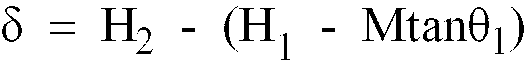
- Based on the difference between the levels δ above, the thickness of pavement T can be calculated by using the following equation.

- H21 :
- Value detected by the second height sensor (14)
- δ:
- Value calculated by the equation (1) above
- M:
- Same as above
- θ2 :
- Tilt of the measuring arm (12)
- H0 :
- Difference between the levels of the height sensor (14) and the screed (5)
- The equations (1) and (2) above are provided for an easier understanding of the method used to calculate the level difference δ and the thickness of pavement T. The method differs slightly from those used by the measuring unit (11) of by the asphalt finisher AF in Figures 1 and 3. To actually take a measurement with the measuring unit (11), the thickness of pavement T is calculated after the tractor unit (1) travels over the distance equal to the spacing M between the height sensors (13) and (14), rather than the
distance 2M between the screed (5) and the second height sensor (14). - In the equations (1) and (2) above, the height difference δ and the thickness of pavement T does not take the tilt θ into consideration. Therefore, the values in the equations are slightly different from the actual values. Nonetheless, such a difference is negligibly small in practice.
- The following paragraphs describe a method for controlling the thickness of the pavement with the leveling machine in the configuration already described.
- The asphalt finisher AF begins by sending a mixed asphalt material in the hopper (2) to the screw through the feeder, while the tractor unit (1) travels at a constant speed as in the conventional system. This material is then uniformly spread in front of the screed (5) which levels the material.
- In the operation above, the distance covered by the tractor unit (1) is measured by the distance sensor (17), and, when the travel distance reaches M, the first height sensor (13) and the second height sensor (14) measure the distance to the base course surface. This measurement result is then forwarded to the arithemtic unit (30).
- The arithmetic unit (30) calculates the thickness of pavement T on the basis of the output signals from the height sensors (13) and (14), the distance sensor (17), and the tilt sensor (15), as described above. On the basis of this calculated pavement thickness, the arithmetic unit (30) also derives the average value Ta of the pavement thickness at multiple continuous measurement points on the paved surface, determining the difference ε between the average value and the preset target thickness of pavement. The determined value is then forwarded to the arithmetic unit (40). Data is sent to the arithmetic unit (40) when the tractor unit travels over a specified distance (for example, 5 m) or at specified time intervals.
- While the tractor unit (1) is travelling, the distance to the base course surface at the distance M in front of the screed (5) is constantly measured by the third height sensor (19), and this measured value is relayed to the arithmetic unit (40).
- The arithmetic unit (40) determines the difference between the value L measured by the third height sensor (19) which has been sent to the arithmetic unit (40) and the predetermined target control value Lo, and, based on that difference, the arithmetic unit (40) determines how to control the pivot cylinder. The target control value Lo can be obtained when the operator specifically presses the specified switch during the initial operation of the asphalt finisher after the operator judges that the operation is steady.
- The control signal for the pivot cylinder described above is sent to the solenoid valve (46) via the I/O interface (44) to extend or retract the pivot cylinder (8), which controls the screed accordingly (5).
- This enables the screed (5) to be controlled, while taking into account the unevenness of the base course, so that the flatness of the finished pavement surface will be ensured. In other words, careful grading control can be achieved.
- When the tractor unit has travelled over the specified distance (for example, 5 m), it is determined, based on the signal sent from the operation unit (33), whether or not the average value Ta of the actual thickness of the pavement is greatly different from the target thickness of the pavement To. If this difference is outside a certain range, the constant Lo is adjusted to an appropriate value.
- This technology ensures flatness for the asphalt finisher, which is an embodiment of the present invention. In addition, if the pavement thickness differs from the target thickness of the pavement, the pavement thickness can be corrected to a value close to the target thickness of the pavement.
- There are several types of leveling machines; a machine which uses wheels instead of crawlers, a machine with ultrasonic or laser height sensors, etc. The detailed structures of such machines depend on individual application.
- In the present invention, the target thickness of the pavement t* is input into the IC card as an initial pavement condition, which is then entered into the control unit (30) by inserting the IC card into an input part. The target thickness of the pavement t* includes the left target thickness of the pavement and the right target thickness of the pavement. This thickness may be set to any value, for example 50 mm or 70 mm. Besides the target thickness of the pavement, the following initial pavement conditions are also entered into the IC card. The setting items and the contents are as follows:
- N Selecting a method to control the thickness of the pavement
- Priority control of the thickness of pavement
- Priority control of the flatness
- Control of the side level
- Control of the cross slope
- Others
- N Selecting the type of mixed material
- Coarse-graded asphalt concrete (20)
- Dense-graded asphalt concrete (20)
- Dense-graded asphalt concrete (13)
- Fine-graded asphalt concrete (13)
- Dense-graded gap asphalt concrete (13)
- Others
- N Determining the width of the pavement
- The width of the pavement can be set corresponding to the width of the road, for example 4.5 m, 4.0 m, or 3.5 m.
- N Setting the planned length of the pavement
The length of pavement can be set to, for example, 500 m or 300 m. - N Setting the density of the mixed material
- The density can be set to, for example, 2.40 t/m3 .
- N Setting the planned working speed
- The speed can be set to, for example, 3.0 m/min.
- The initial paving conditions are usually written onto the IC card at the office. The IC card containing these initial conditions is delivered to the operator, who then inserts the IC card into the input slot of the operation board. When the IC card is inserted in the input slot, the settings of the IC card are displayed on the Initial Conditions Setting screen (38) (Figure 6) of the display unit. The operator can, therefore, confirm the initial conditions from the display on the Initial Conditions Setting screen (38) before starting the paving work.
- When the paving work is finished, the operator removes the IC card from the input slot and returns it to the office.
- If the IC card containing the initial paving conditions for the road to be paved is not provided, or part of the initial paving conditions contained in the IC card have to be modified, the operator should type the required initial paving conditions into the control unit (30) from a keyboard (not illustrated) near the input slot or at the control panel to make any required modifications.
- The IC card stores the date and time, name of the mixed asphalt material, changes in the thickness of the pavement, width of the pavement, covered distance, amount of mixed material used, and any other required operation data. After the pavement work has been finished, the IC card is removed from the machine, and is used to manage the pavement construction.
- Examined samples and technical items other than those described above are as follows:
- (1) The embodiment samples mentioned above set the distance between the height sensors (13) and (14) as "M". However, this distance may be 2M, M/2, or M/3. Using the distance, M/2 or M/3, may enable the measuring unit (11) to be more compact.
- (2) The height sensors (13), (14), and (19) need not necessarily be the ultranonic type. They may also be the laser type, or the telescopic type. The specific structure of the sensors is optional.
- Since the present invention ensures the flatness of the paved surface, without using any special devices such as the averaging beam described in the section summarizing the "conventional technology", and controls the tilting angle of the screed, feeding back any difference between the actual thickness of the pavement calculated from data from a pair of the height sensors and the target thickness of pavement, the present invention is very effective in ensuring that the thickness of the pavement will be very close to the desired value.
- In addition, the present invention enables the thickness of the pavement and other operating conditions to be set quickly and accurately.
Claims (7)
- A pavement thickness control apparatus for controlling pavement thickness, the apparatus for use in a pavement surface finisher having a traveling tractor unit (1) which travels as it supplies asphalt material to a road surface, a screed (5) which is pivotable about a horizontal axis perpendicular to a direction of travel of said tractor unit (1) for paving the road surface by evenly spreading said asphalt material, and an inclining means (8) for inclining said screed (5) in order to control said pavement thickness, said pavement thickness control apparatus being characterized in comprising:measuring means consisting of at least a first and a second height sensors (13, 14) disposed in front of said screed (5) having a predetermined distance therebetween along a direction of movement of said tractor unit (1), for measuring the height from said sensors to an unpaved surface;an unpaved surface height sensor (19) disposed in front, and in proximity to, said screed (5), for measuring the height above an unpaved surface at a target position to be paved;a first calculating means (30) for calculating a first difference between a preset target pavement thickness and a calculated pavement thickness based on heights measured by said measuring means (13, 14);a second calculating means (40) for calculating a second difference between a preset target height and heights above an unpaved surface measured by said unpaved surface height sensor (19), and for further calculating a control value for controlling said inclining means (8) of the screed (5) based on said first and second differences.
- A pavement thickness control apparatus according to claim 1 , characterized in that said apparatus further comprises a tilt sensor (15) for measuring a tilting angle of a supporting means (12), on which said height sensors (13, 14) are disposed, and said first calculating means (30) calculates said pavement thickness, based on measurement data of said tilt sensor (15) and said height sensors (13, 14).
- A pavement thickness control apparatus according to claim 2, characterized in that said measuring means, having said first and second height sensors (13, 14) and said tilt sensor (15), are affixed to said supporting means consisting of the arm (12), which is inclined in a manner corresponding to that of said screed (5).
- A pavement thickness control apparatus according to claim 1 , characterized in that said first calculating means (30) determines a first difference between the target pavement thickness and an average pavement thickness obtained by calculation from a plurality of said pavement thicknesses measured at a plurality of measurement points, based on sequentially measured heights, which are measured by said measuring means (13,14) each time said pavement surface finisher (AF) travels said predetermined distance, and a relative distance between said height sensors (13, 14).
- A pavement thickness control apparatus according to claim 4 , characterized in that said apparatus further comprises a distance sensor (17) for measuring a distance the pavement surface finisher (AF) has run;said height sensors (13, 14, 19) have a predetermined distance (M) from each other along the direction of movement of said tractor unit (1); andsaid first calculating means calculates the pavement thickness each time said distance sensor (17) records a predetermined distance (M) as the travel distance of the pavement surface finisher (AF).
- A pavement thickness control apparatus according to claim 1 , characterized in that said pavement thickness control apparatus has an input portion for receiving a recording medium, on which is recorded information relating to operating conditions of the pavement surface finisher (AF) including the preset target pavement thickness, and which reads out said recorded information from said recording medium and transmits said information to said first calculating means (30).
- A pavement thickness control apparatus according to claim 6, characterized in that said input portion further comprises a key board for inputting initial paving conditions into said first calculating means (30), and for revising said initial paving conditions recorded in said recording medium.
Applications Claiming Priority (5)
| Application Number | Priority Date | Filing Date | Title |
|---|---|---|---|
| JP307582/90 | 1990-11-14 | ||
| JP307588/90 | 1990-11-14 | ||
| JP30758290A JPH0749641B2 (en) | 1990-11-14 | 1990-11-14 | Pavement thickness control method for leveling machine |
| JP2307588A JPH0749645B2 (en) | 1990-11-14 | 1990-11-14 | Pavement thickness control method for leveling machine |
| PCT/JP1991/001560 WO1992008847A1 (en) | 1990-11-14 | 1991-11-14 | Method of controlling pavement thickness in motor grader and method of setting conditions for automatic control |
Publications (3)
| Publication Number | Publication Date |
|---|---|
| EP0510215A1 EP0510215A1 (en) | 1992-10-28 |
| EP0510215A4 EP0510215A4 (en) | 1993-05-05 |
| EP0510215B1 true EP0510215B1 (en) | 1997-05-07 |
Family
ID=26565172
Family Applications (1)
| Application Number | Title | Priority Date | Filing Date |
|---|---|---|---|
| EP91919801A Expired - Lifetime EP0510215B1 (en) | 1990-11-14 | 1991-11-14 | Pavement thickness control apparatus |
Country Status (5)
| Country | Link |
|---|---|
| US (1) | US5393167A (en) |
| EP (1) | EP0510215B1 (en) |
| KR (1) | KR100206726B1 (en) |
| DE (1) | DE69126017T2 (en) |
| WO (1) | WO1992008847A1 (en) |
Cited By (4)
| Publication number | Priority date | Publication date | Assignee | Title |
|---|---|---|---|---|
| EP2535456A1 (en) | 2011-06-15 | 2012-12-19 | Joseph Vögele AG | Road finisher with coating measuring device |
| EP2535457A1 (en) | 2011-06-15 | 2012-12-19 | Joseph Vögele AG | Road finisher with coating measuring device |
| EP2535458A1 (en) | 2011-06-15 | 2012-12-19 | Joseph Vögele AG | Road finisher with coating measuring device |
| US11669073B2 (en) * | 2020-11-24 | 2023-06-06 | Caterpillar Trimble Control Technologies Llc | Velocity control for construction machines |
Families Citing this family (72)
| Publication number | Priority date | Publication date | Assignee | Title |
|---|---|---|---|---|
| US5318378A (en) * | 1992-09-28 | 1994-06-07 | Caterpillar Paving Products Inc. | Method and apparatus for controlling a cold planer in response to a kickback event |
| US5362176A (en) * | 1993-01-11 | 1994-11-08 | Aw-2R, Inc. | Road construction apparatus and methods |
| JP2505210Y2 (en) * | 1993-04-09 | 1996-07-24 | 建設省東北地方建設局長 | Automatic steering device for paving vehicles |
| AU1832795A (en) * | 1994-01-21 | 1995-08-08 | George W. Swisher Jr. | Paving material machine having a tunnel with automatic gate control |
| US5568992A (en) * | 1995-05-19 | 1996-10-29 | Caterpillar Paving Products Inc. | Screed control system for an asphalt paver and method of use |
| US5599134A (en) * | 1995-09-15 | 1997-02-04 | Cedarapids, Inc. | Asphalt paver with compaction compensating system |
| US5752783A (en) * | 1996-02-20 | 1998-05-19 | Blaw-Knox Construction Equipment Corporation | Paver with radar screed control |
| DE19647150C2 (en) * | 1996-11-14 | 2001-02-01 | Moba Mobile Automation Gmbh | Device and method for controlling the installation height of a road finisher |
| DE19709131C2 (en) * | 1997-03-06 | 2003-02-20 | Abg Allg Baumaschinen Gmbh | pavers |
| WO1999027189A1 (en) * | 1997-11-20 | 1999-06-03 | Gvs Mbh & Co. Kg | Combination of insertion devices for inserting and pre-compressing asphalt layers |
| NL1009364C2 (en) * | 1998-06-10 | 1999-12-13 | Road Ware B V | Device for determining a profile of a road surface. |
| US6588976B2 (en) | 1999-12-17 | 2003-07-08 | Delaware Capital Formation, Inc. | Concrete placing and screeding apparatus and method |
| US6623208B2 (en) | 1999-12-17 | 2003-09-23 | Delaware Capital Formation, Inc. | Concrete placing and screeding apparatus and method |
| US6398454B1 (en) * | 2000-01-24 | 2002-06-04 | Romolo Bitelli | Vibratory finishing machine for road asphalting |
| DE10025462A1 (en) * | 2000-05-23 | 2001-12-06 | Moba Mobile Automation Gmbh | Determination of layer thickness of final surface coat applied by surface finishing machine using inclination sensor |
| DE10025474B4 (en) * | 2000-05-23 | 2011-03-10 | Moba - Mobile Automation Gmbh | Coating thickness determination by relative position detection between the tractor and the traction arm of a paver |
| DE10060903C2 (en) * | 2000-12-07 | 2002-10-31 | Moba Mobile Automation Gmbh | Laser height control device for a construction machine |
| US6543962B2 (en) * | 2001-03-29 | 2003-04-08 | Koch Industries, Inc. | Screed assembly with improved sensitivity and response to varying surface conditions |
| US6520715B1 (en) * | 2001-08-10 | 2003-02-18 | John Paul Smith | Asphalt delivery and compaction system |
| US7044680B2 (en) | 2002-03-15 | 2006-05-16 | Gomaco Corporation | Method and apparatus for calculating and using the profile of a surface |
| US8682622B1 (en) | 2002-03-15 | 2014-03-25 | Gomaco Corporation | Smoothness indicator analysis system |
| US7850395B1 (en) | 2002-03-15 | 2010-12-14 | GOMACO Corporation a division of Godbersen Smith Construction Co. | Smoothness indicator analysis system |
| DE10234217B4 (en) * | 2002-07-27 | 2009-02-05 | Hermann Kirchner Gmbh & Co Kg | Method and device for determining the thickness of an asphalt layer |
| KR101035448B1 (en) * | 2003-02-13 | 2011-05-18 | 존 폴 스미스 | Asphalt Mat Sedimentation Method |
| US7316520B2 (en) * | 2003-04-21 | 2008-01-08 | Semmaterials, L.P. | Low surface area shearing device |
| US7108450B2 (en) * | 2003-10-17 | 2006-09-19 | Semmaterials, L.P. | Portable drag box with automated shearing device |
| US20050260035A1 (en) * | 2004-05-21 | 2005-11-24 | Dabramo Tony F | Concrete finishing apparatus and method for finishing freshly poured or partially cured concrete |
| US7172363B2 (en) * | 2004-08-31 | 2007-02-06 | Caterpillar Paving Products Inc | Paving machine output monitoring system |
| US9963836B1 (en) | 2005-02-23 | 2018-05-08 | Gomaco Corporation | Method for operating paving train machines |
| US20060198700A1 (en) * | 2005-03-04 | 2006-09-07 | Jurgen Maier | Method and system for controlling construction machine |
| AU2006298516B2 (en) * | 2005-10-05 | 2011-03-03 | Mechanical System Dynamics Pty Ltd | Measurement of pavement unevenness |
| WO2007039815A1 (en) * | 2005-10-05 | 2007-04-12 | Mechanical System Dynamics Pty Ltd | Measurement of pavement unevenness |
| KR100729148B1 (en) * | 2006-06-01 | 2007-06-18 | 유석준 | Waterproof material applicator |
| US7484911B2 (en) * | 2006-08-08 | 2009-02-03 | Caterpillar Inc. | Paving process and machine with feed forward material feed control system |
| US8061180B2 (en) * | 2008-03-06 | 2011-11-22 | Caterpillar Trimble Control Technologies Llc | Method of valve calibration |
| US7946787B2 (en) * | 2008-06-27 | 2011-05-24 | Caterpillar Inc. | Paving system and method |
| US8070385B2 (en) * | 2008-07-21 | 2011-12-06 | Caterpillar Trimble Control Technologies, Llc | Paving machine control and method |
| US20100129152A1 (en) * | 2008-11-25 | 2010-05-27 | Trimble Navigation Limited | Method of covering an area with a layer of compressible material |
| US8220806B2 (en) | 2009-01-13 | 2012-07-17 | Roger Hartel Neudeck | Surface milling system |
| DE102009019839A1 (en) † | 2009-03-09 | 2010-09-16 | Bomag Gmbh | Hydraulic control arrangement for the screed of a road paver |
| US8892367B2 (en) | 2009-10-16 | 2014-11-18 | Dynatest International A/S | Determination of subgrade modulus and stiffness of pavement layers for measurement of bearing capacity under fast moving wheel load |
| AU2010307334B2 (en) * | 2009-10-16 | 2016-12-01 | Dynatest International A/S | Triangulation of pavement deflections using more than four sensors |
| US8371769B2 (en) * | 2010-04-14 | 2013-02-12 | Caterpillar Trimble Control Technologies Llc | Paving machine control and method |
| US8395542B2 (en) | 2010-08-27 | 2013-03-12 | Trimble Navigation Limited | Systems and methods for computing vertical position |
| US8930092B2 (en) * | 2011-05-10 | 2015-01-06 | Mark MINICH | Integrated paving process control for a paving operation |
| US8636442B1 (en) * | 2012-12-14 | 2014-01-28 | Caterpillar Paving Products Inc. | Integrated generator for screed plate heat up |
| US9045871B2 (en) | 2012-12-27 | 2015-06-02 | Caterpillar Paving Products Inc. | Paving machine with operator directed saving and recall of machine operating parameters |
| PL2789740T3 (en) | 2013-04-12 | 2018-05-30 | Joseph Vögele AG | Base temperature measurement by means of a road finisher |
| EP2921588B1 (en) * | 2014-03-18 | 2016-12-14 | MOBA - Mobile Automation AG | Road finisher with layer thickness detection device and method for detecting the thickness of an installed material layer |
| CN104568483B (en) * | 2014-12-25 | 2017-03-29 | 长安大学 | Road-bridge transition section flatness comfortableness field evaluation method and method of tire |
| US9873990B2 (en) * | 2015-07-30 | 2018-01-23 | Caterpillar Paving Products Inc. | Paving machine having production monitoring system |
| US9803324B2 (en) | 2016-01-26 | 2017-10-31 | Deere & Company | Ejector control for spreading material according to a profile |
| EP3228748B1 (en) | 2016-04-08 | 2018-07-18 | Joseph Vögele AG | Road finisher with holding device |
| PL3228747T3 (en) | 2016-04-08 | 2018-11-30 | Joseph Vögele AG | Road finisher with holding device for holding and positioning a sensor unit |
| GB2554872B (en) * | 2016-10-07 | 2019-12-04 | Kelly Anthony | A compaction compensation system |
| EP3382098B1 (en) | 2017-03-29 | 2019-03-27 | Joseph Vögele AG | Road finisher with holding device for holding and positioning a sensor unit |
| US10472777B1 (en) * | 2018-05-02 | 2019-11-12 | Caterpillar Paving Products Inc. | Screed tow point assembly for paver |
| KR102124695B1 (en) * | 2018-07-31 | 2020-06-18 | 백승한 | floor material auto leveling apparatus |
| EP3739122B1 (en) * | 2019-05-14 | 2021-04-28 | Joseph Vögele AG | Road finisher and method for determining a thickness of a layer of an established installation layer |
| EP3795748B1 (en) * | 2019-09-20 | 2022-08-31 | MOBA Mobile Automation AG | Levelling system for a road construction machine |
| CN115917245A (en) | 2020-01-31 | 2023-04-04 | 摩巴自动控制股份有限公司 | Measurement Systems and Controllers |
| EP3981918B1 (en) | 2020-10-08 | 2024-03-13 | Joseph Vögele AG | Road finisher and method for levelling the screed of a finisher |
| CN112647390A (en) * | 2020-12-11 | 2021-04-13 | 中山火炬职业技术学院 | Method for monitoring flatness of asphalt pavement |
| PL4056760T3 (en) * | 2021-03-12 | 2024-02-19 | Joseph Vögele AG | Road finisher with levelling cascade control |
| EP4063564B1 (en) * | 2021-03-23 | 2025-03-05 | MOBA Mobile Automation AG | Measuring system |
| CN115538259A (en) * | 2021-06-29 | 2022-12-30 | 江苏奥新科技有限公司 | An automatic thickness measurement balance beam and thickness measurement leveling method |
| DE102022201294A1 (en) * | 2022-02-08 | 2023-08-10 | Moba Mobile Automation Aktiengesellschaft | Leveling system for a construction machine |
| JP7753613B2 (en) * | 2022-05-24 | 2025-10-15 | 住友建機株式会社 | Road machinery and road machinery support systems |
| EP4303365B1 (en) * | 2022-07-04 | 2026-03-11 | Joseph Vögele AG | Road finisher and method for controlling the operation thereof |
| CN116517624A (en) * | 2023-05-11 | 2023-08-01 | 国能神东煤炭集团有限责任公司 | Automatic control system and method for conveying and distributing materials of mining explosion-proof paver |
| EP4495323A1 (en) | 2023-07-17 | 2025-01-22 | MOBA Mobile Automation AG | Sensor system for a construction machine |
| CN117364580A (en) * | 2023-09-22 | 2024-01-09 | 中铁十局集团有限公司 | A construction method for real-time intelligent measurement of roadbed rolling settlement |
Family Cites Families (10)
| Publication number | Priority date | Publication date | Assignee | Title |
|---|---|---|---|---|
| JPS63121606U (en) * | 1987-01-27 | 1988-08-08 | ||
| JP2584823B2 (en) * | 1988-04-22 | 1997-02-26 | 株式会社トキメック | Pavement thickness measuring device |
| JPH01278603A (en) * | 1988-04-27 | 1989-11-09 | Sumitomo Heavy Ind Ltd | Pavement thickness detecting device |
| JP2530000B2 (en) * | 1988-05-23 | 1996-09-04 | 株式会社トキメック | Pavement leveling thickness measurement management system |
| US4988233A (en) * | 1988-12-30 | 1991-01-29 | Kasler Corporation | Paving machine |
| JP2772537B2 (en) * | 1989-03-10 | 1998-07-02 | 日立建機株式会社 | Construction machinery |
| DE3909583A1 (en) * | 1989-03-23 | 1990-10-18 | Abg Werke Gmbh | ROAD PAVERS |
| JPH02261105A (en) * | 1989-03-31 | 1990-10-23 | Niigata Eng Co Ltd | Pavement thickness measuring device in leveling machine |
| JPH02270653A (en) * | 1989-04-12 | 1990-11-05 | Yutani Heavy Ind Ltd | Operation diagnosing device for construction machinery |
| US5328295A (en) * | 1992-06-26 | 1994-07-12 | Allen Engineering Corporation | Torsional automatic grade control system for concrete finishing |
-
1991
- 1991-11-14 KR KR1019920700579A patent/KR100206726B1/en not_active Expired - Fee Related
- 1991-11-14 EP EP91919801A patent/EP0510215B1/en not_active Expired - Lifetime
- 1991-11-14 DE DE69126017T patent/DE69126017T2/en not_active Expired - Fee Related
- 1991-11-14 WO PCT/JP1991/001560 patent/WO1992008847A1/en not_active Ceased
-
1993
- 1993-10-18 US US08/138,828 patent/US5393167A/en not_active Expired - Fee Related
Cited By (8)
| Publication number | Priority date | Publication date | Assignee | Title |
|---|---|---|---|---|
| EP2535456A1 (en) | 2011-06-15 | 2012-12-19 | Joseph Vögele AG | Road finisher with coating measuring device |
| EP2535457A1 (en) | 2011-06-15 | 2012-12-19 | Joseph Vögele AG | Road finisher with coating measuring device |
| EP2535458A1 (en) | 2011-06-15 | 2012-12-19 | Joseph Vögele AG | Road finisher with coating measuring device |
| US8696237B2 (en) | 2011-06-15 | 2014-04-15 | Joseph Vogele Ag | Road paver with layer thickness measuring device |
| US8702344B2 (en) | 2011-06-15 | 2014-04-22 | Joseph Vogele Ag | Road paver with layer thickness measuring device |
| US9033611B2 (en) | 2011-06-15 | 2015-05-19 | Joseph Vogele Ag | Road paver with layer thickness measuring device |
| US11669073B2 (en) * | 2020-11-24 | 2023-06-06 | Caterpillar Trimble Control Technologies Llc | Velocity control for construction machines |
| US12487584B2 (en) * | 2020-11-24 | 2025-12-02 | Caterpillar Trimble Control Technologies Llc | Velocity control for construction machines |
Also Published As
| Publication number | Publication date |
|---|---|
| KR920702454A (en) | 1992-09-04 |
| KR100206726B1 (en) | 1999-07-01 |
| DE69126017D1 (en) | 1997-06-12 |
| EP0510215A4 (en) | 1993-05-05 |
| WO1992008847A1 (en) | 1992-05-29 |
| US5393167A (en) | 1995-02-28 |
| EP0510215A1 (en) | 1992-10-28 |
| DE69126017T2 (en) | 1997-11-06 |
Similar Documents
| Publication | Publication Date | Title |
|---|---|---|
| EP0510215B1 (en) | Pavement thickness control apparatus | |
| US11629463B2 (en) | Machine train composed of road milling machine and road finisher, and method for operating road milling machine and road finisher | |
| US11555278B2 (en) | Autowidth input for paving operations | |
| US5549412A (en) | Position referencing, measuring and paving method and apparatus for a profiler and paver | |
| US7172363B2 (en) | Paving machine output monitoring system | |
| US9702096B2 (en) | Automotive construction machine and method for controlling an automotive construction machine | |
| CN109914203B (en) | Road finishing machine and method for automatically controlling the pull point height of a levelling cylinder of a road finishing machine | |
| US11001977B2 (en) | Paving machine for applying varying crown profiles | |
| US9873990B2 (en) | Paving machine having production monitoring system | |
| CN108350669A (en) | Truck position control system for milling machine operation | |
| US7850395B1 (en) | Smoothness indicator analysis system | |
| US3029716A (en) | Paving machine control system | |
| US8682622B1 (en) | Smoothness indicator analysis system | |
| US7559718B2 (en) | Transducer arrangement | |
| JPH0749645B2 (en) | Pavement thickness control method for leveling machine | |
| CN112012083A (en) | Method and system for positioning a screed plate | |
| JP2903719B2 (en) | How to operate the leveling machine | |
| JPH0743132Y2 (en) | Operating device for leveling machine | |
| JPH0749646B2 (en) | Pavement thickness control method for leveling machine | |
| US12590423B2 (en) | Edge slump control | |
| EP4384960B1 (en) | Method of setting the working parameters of the construction machine when repairing the road surface or laying the construction layer and a device for carrying out this method | |
| JPH07885B2 (en) | Road paving method using a leveling machine | |
| JPH04179712A (en) | Pavement monitoring method for paving machine | |
| JPH0823125B2 (en) | Laying machine | |
| JPH04179707A (en) | Pavement thickness controlling method for paving machine |
Legal Events
| Date | Code | Title | Description |
|---|---|---|---|
| PUAI | Public reference made under article 153(3) epc to a published international application that has entered the european phase |
Free format text: ORIGINAL CODE: 0009012 |
|
| AK | Designated contracting states |
Kind code of ref document: A1 Designated state(s): DE FR GB IT |
|
| 17P | Request for examination filed |
Effective date: 19921024 |
|
| A4 | Supplementary search report drawn up and despatched |
Effective date: 19930315 |
|
| AK | Designated contracting states |
Kind code of ref document: A4 Designated state(s): DE FR GB IT |
|
| 17Q | First examination report despatched |
Effective date: 19950328 |
|
| GRAG | Despatch of communication of intention to grant |
Free format text: ORIGINAL CODE: EPIDOS AGRA |
|
| GRAH | Despatch of communication of intention to grant a patent |
Free format text: ORIGINAL CODE: EPIDOS IGRA |
|
| GRAH | Despatch of communication of intention to grant a patent |
Free format text: ORIGINAL CODE: EPIDOS IGRA |
|
| GRAA | (expected) grant |
Free format text: ORIGINAL CODE: 0009210 |
|
| RAP1 | Party data changed (applicant data changed or rights of an application transferred) |
Owner name: NIPPON HODO CO., LTD Owner name: NIIGATA ENGINEERING CO., LTD. |
|
| AK | Designated contracting states |
Kind code of ref document: B1 Designated state(s): DE FR GB IT |
|
| REF | Corresponds to: |
Ref document number: 69126017 Country of ref document: DE Date of ref document: 19970612 |
|
| ET | Fr: translation filed | ||
| PLBE | No opposition filed within time limit |
Free format text: ORIGINAL CODE: 0009261 |
|
| STAA | Information on the status of an ep patent application or granted ep patent |
Free format text: STATUS: NO OPPOSITION FILED WITHIN TIME LIMIT |
|
| 26N | No opposition filed | ||
| REG | Reference to a national code |
Ref country code: GB Ref legal event code: IF02 |
|
| PGFP | Annual fee paid to national office [announced via postgrant information from national office to epo] |
Ref country code: FR Payment date: 20030929 Year of fee payment: 13 |
|
| PGFP | Annual fee paid to national office [announced via postgrant information from national office to epo] |
Ref country code: GB Payment date: 20031107 Year of fee payment: 13 Ref country code: DE Payment date: 20031107 Year of fee payment: 13 |
|
| PG25 | Lapsed in a contracting state [announced via postgrant information from national office to epo] |
Ref country code: GB Free format text: LAPSE BECAUSE OF NON-PAYMENT OF DUE FEES Effective date: 20041114 |
|
| PG25 | Lapsed in a contracting state [announced via postgrant information from national office to epo] |
Ref country code: DE Free format text: LAPSE BECAUSE OF NON-PAYMENT OF DUE FEES Effective date: 20050601 |
|
| GBPC | Gb: european patent ceased through non-payment of renewal fee |
Effective date: 20041114 |
|
| PG25 | Lapsed in a contracting state [announced via postgrant information from national office to epo] |
Ref country code: FR Free format text: LAPSE BECAUSE OF NON-PAYMENT OF DUE FEES Effective date: 20050729 |
|
| REG | Reference to a national code |
Ref country code: FR Ref legal event code: ST |
|
| PG25 | Lapsed in a contracting state [announced via postgrant information from national office to epo] |
Ref country code: IT Free format text: LAPSE BECAUSE OF NON-PAYMENT OF DUE FEES;WARNING: LAPSES OF ITALIAN PATENTS WITH EFFECTIVE DATE BEFORE 2007 MAY HAVE OCCURRED AT ANY TIME BEFORE 2007. THE CORRECT EFFECTIVE DATE MAY BE DIFFERENT FROM THE ONE RECORDED. Effective date: 20051114 |