EP0510044B1 - Foldable partition - Google Patents
Foldable partition Download PDFInfo
- Publication number
- EP0510044B1 EP0510044B1 EP91902059A EP91902059A EP0510044B1 EP 0510044 B1 EP0510044 B1 EP 0510044B1 EP 91902059 A EP91902059 A EP 91902059A EP 91902059 A EP91902059 A EP 91902059A EP 0510044 B1 EP0510044 B1 EP 0510044B1
- Authority
- EP
- European Patent Office
- Prior art keywords
- partition
- panels
- panel
- hinges
- hinge
- Prior art date
- Legal status (The legal status is an assumption and is not a legal conclusion. Google has not performed a legal analysis and makes no representation as to the accuracy of the status listed.)
- Expired - Lifetime
Links
- 238000005192 partition Methods 0.000 title claims abstract description 93
- 230000033001 locomotion Effects 0.000 claims abstract description 25
- 230000000977 initiatory effect Effects 0.000 claims abstract description 7
- 230000000149 penetrating effect Effects 0.000 claims 1
- 238000007789 sealing Methods 0.000 abstract description 20
- 239000000463 material Substances 0.000 description 12
- 238000010168 coupling process Methods 0.000 description 7
- 238000005859 coupling reaction Methods 0.000 description 7
- 230000008878 coupling Effects 0.000 description 6
- 230000008439 repair process Effects 0.000 description 6
- 230000009471 action Effects 0.000 description 5
- 238000001125 extrusion Methods 0.000 description 5
- 210000003128 head Anatomy 0.000 description 5
- 230000008901 benefit Effects 0.000 description 3
- 238000013023 gasketing Methods 0.000 description 3
- 239000011521 glass Substances 0.000 description 3
- 238000009413 insulation Methods 0.000 description 3
- 238000002955 isolation Methods 0.000 description 3
- 230000007246 mechanism Effects 0.000 description 3
- 239000012858 resilient material Substances 0.000 description 3
- 239000011358 absorbing material Substances 0.000 description 2
- 230000009977 dual effect Effects 0.000 description 2
- 230000000694 effects Effects 0.000 description 2
- 229910052751 metal Inorganic materials 0.000 description 2
- 239000002184 metal Substances 0.000 description 2
- 238000000034 method Methods 0.000 description 2
- 230000004048 modification Effects 0.000 description 2
- 238000012986 modification Methods 0.000 description 2
- 239000003566 sealing material Substances 0.000 description 2
- 229910000831 Steel Inorganic materials 0.000 description 1
- 238000010521 absorption reaction Methods 0.000 description 1
- 230000004075 alteration Effects 0.000 description 1
- 229910052782 aluminium Inorganic materials 0.000 description 1
- XAGFODPZIPBFFR-UHFFFAOYSA-N aluminium Chemical compound [Al] XAGFODPZIPBFFR-UHFFFAOYSA-N 0.000 description 1
- 230000005540 biological transmission Effects 0.000 description 1
- 229910052918 calcium silicate Inorganic materials 0.000 description 1
- 239000000378 calcium silicate Substances 0.000 description 1
- OYACROKNLOSFPA-UHFFFAOYSA-N calcium;dioxido(oxo)silane Chemical compound [Ca+2].[O-][Si]([O-])=O OYACROKNLOSFPA-UHFFFAOYSA-N 0.000 description 1
- 238000013016 damping Methods 0.000 description 1
- 230000001419 dependent effect Effects 0.000 description 1
- 239000013536 elastomeric material Substances 0.000 description 1
- 239000000835 fiber Substances 0.000 description 1
- 229920002457 flexible plastic Polymers 0.000 description 1
- 239000003999 initiator Substances 0.000 description 1
- 238000009434 installation Methods 0.000 description 1
- 230000003993 interaction Effects 0.000 description 1
- 238000004519 manufacturing process Methods 0.000 description 1
- 239000002557 mineral fiber Substances 0.000 description 1
- 239000002991 molded plastic Substances 0.000 description 1
- 239000004033 plastic Substances 0.000 description 1
- 229920003023 plastic Polymers 0.000 description 1
- 230000004044 response Effects 0.000 description 1
- 125000006850 spacer group Chemical group 0.000 description 1
- 239000010959 steel Substances 0.000 description 1
- 239000012780 transparent material Substances 0.000 description 1
- 239000002023 wood Substances 0.000 description 1
Images




Classifications
-
- E—FIXED CONSTRUCTIONS
- E05—LOCKS; KEYS; WINDOW OR DOOR FITTINGS; SAFES
- E05D—HINGES OR SUSPENSION DEVICES FOR DOORS, WINDOWS OR WINGS
- E05D15/00—Suspension arrangements for wings
- E05D15/26—Suspension arrangements for wings for folding wings
-
- E—FIXED CONSTRUCTIONS
- E06—DOORS, WINDOWS, SHUTTERS, OR ROLLER BLINDS IN GENERAL; LADDERS
- E06B—FIXED OR MOVABLE CLOSURES FOR OPENINGS IN BUILDINGS, VEHICLES, FENCES OR LIKE ENCLOSURES IN GENERAL, e.g. DOORS, WINDOWS, BLINDS, GATES
- E06B3/00—Window sashes, door leaves, or like elements for closing wall or like openings; Layout of fixed or moving closures, e.g. windows in wall or like openings; Features of rigidly-mounted outer frames relating to the mounting of wing frames
- E06B3/92—Doors or windows extensible when set in position
- E06B3/94—Doors of the bellows type
-
- E—FIXED CONSTRUCTIONS
- E05—LOCKS; KEYS; WINDOW OR DOOR FITTINGS; SAFES
- E05Y—INDEXING SCHEME ASSOCIATED WITH SUBCLASSES E05D AND E05F, RELATING TO CONSTRUCTION ELEMENTS, ELECTRIC CONTROL, POWER SUPPLY, POWER SIGNAL OR TRANSMISSION, USER INTERFACES, MOUNTING OR COUPLING, DETAILS, ACCESSORIES, AUXILIARY OPERATIONS NOT OTHERWISE PROVIDED FOR, APPLICATION THEREOF
- E05Y2900/00—Application of doors, windows, wings or fittings thereof
- E05Y2900/20—Application of doors, windows, wings or fittings thereof for furniture, e.g. cabinets
Definitions
- a folding partition having two rows of spaced, pivotally associated rigid panels supported by a trackway or the like with a control mechanism providing movements of the panels from a flat-lined condition when the partition is in closed position to an open position in which the panels are oriented in opposed surface to surface stacked relation generally in perpendicular relation to the position of the panels when in closed position is known.
- the panels are respectively separated by intermediate strips.
- the hinge mechanism with this folding partition is complicated and therefore expensive. Furthermore, the hinge mechanism used is difficult to assemble and dismantle.
- the present invention therefore seeks to provide inexpensive hinge means for folding partitions, which can easily be assembled and dismantled.
- the pairs of panel elements 2, 2' are interconnected by so-called curled-up hinges 4 having platelike hinge parts 5, 6, which are connected by fixing screws 7 to the inside surfaces of respective panel elements 2, 2' in the manner described such that the vertically spaced apart curled-up eyes are meshing and disposed in the gap between the panel elements 2, 2'.
- the hinge pin 12 is provided at its top with a head 11 and extends with a clearance through the aligned bores of the curled-up eyes 8, 9, so that pin 12 can be readily removed.
- top hinge 4 is spaced sufficiently below the top edge of panels 2, 2' that pin 12 can be lifted vertically and removed from eyelets 8,9.
- the double-link hinges 20 preferred in the present invention are of the kind made and sold by Salice America, Inc., of Charlotte, NC, especially the Salice 100, 200 or F, models C1A6, C2A7, C2A6, C2A9 and CFA7 equipped with DOMI®. rapid assembly mounting plates. Use of the DOMI®. automatic assembly enables the hinge to be attached and detached from the mounting plate with only slight pressure thereby facilitating quick attachments and detachment for assembly or repair.
- Other like hinges are commercially available, e.g.: from Jiouss Blum Inc. of Stanley, N.C. under the trademark BLUM® "clip" concealed hinges.
- the cleats 15 which interconnect pairs of opposed carrying bars 3 are provided at the top with a trolley carrying freely rotatable, axle mounted rollers 51 with the axle mounted on trolley-carrying shanks 50.
- the rollers 51 roll on a track 54, more specifically on flanges which form the rails of track 54 which are inwardly angled toward each other.
- the track 54 is secured to a base 112 such as by screws 114.
- Track 54 is covered on its outside surfaces by bars, boards or panels 55.
- the inside surfaces of the carrying bars 3 and the outside surfaces of the bars 55 define narrow gaps, which are bridged by strip-shaped seals 57 of any suitable acoustical or sound absorbing material. Seals 57 can be secured to the inside surfaces of the carrying bars 3 or outside surface of bars 55.
- sealing strips 58 see Figure 5 also of a suitable acoustical or sound absorbing material, which in the closed state of the door are also in sealing contact with the covering bars 55. These sealing strips will also avoid an occurrence of striking sounds when the folding door is closed at a higher extension speed.
- Figure 4 shows in its bottom right-hand part a different embodiment of a seal in the gap between two panel elements.
- That seal consists of a strip 60, which is made from known sound-proofing sealing material, such as a flexible plastic, and extends throughout the height of the panel elements 2, 2'.
- Strip 60 at one of its edges is secured by screws 61 to the inside surface of the one panel element 2'.
- the sealing strip 60 covers the small gap 62 between two panel elements 2, 2'.
- the juxtaposed opposite panel element 2 is provided on the inside surface of its edge portion with a flat receiving slot, which is defined by inverted U shaped channel members 63, which have been attached by screw 64.
- Figures 8 and 10 show the stationary stop bars or jamb post 70, which is fixed on the wall or the door post in the direction of the opening movement of the partition and which during an opening movement of the partition is telescopically straddled by the leading or terminal carrying bars or posts 3, which are interconnected by the cleats 15.
- the terminal leading carrying bars 3 are extended beyond the cleats 15 toward the carrying wall to constitute forks, which can telescopically straddle the stop bar or jamb post 70 during the opening movement.
- a threaded closing stop 130 is fixed to the stop bar 70 and extends horizontally through a hole in lower cleat 15 terminating in a head 132 substantially larger than the hole. Stop 130 is threaded to allow adjustment.
- stop 130 and head 132 limit travel of the first lower cleat 15, as shown.
- starting upset brackets 134 are horizontally aligned to be struck by the first pair of angles 30 to initiate the opening sequence of the first pair of panels 2, 2'.
- the hinges between the panel elements 2, 2' consist of furniture hinges, in particular, loose pin hinges.
- furniture hinges known per se affords the great advantage that the assembling is simple and access for repairs or servicing is simple and easy.
- Hinges 4 are then accessible because the panel elements have been pivotally moved through about 180 degrees (90° each) relative to each other from their closed position and are now juxtaposed approximately parallel to each other but horizontally spaced apart.
- hinges 4 between two panel elements When the hinges 4 between two panel elements have been disconnected, these panel elements can freely be swung out. Hinges 20 connected to the carrying bars 3 become also readily accessible and a replacement can easily be effected by disconnecting hinges 20 and removing the panel and substituting another. Repairs can be made also in the interior between the two sides of the partition since the cavity is fully accessible through the opening created by the swung out panels.
- hinges 20 having hinge parts which are pivotally movable relative to each other and are connected by two links in each hinge.
- Such hinges are usually called “cup hinges” because their pivotally movable hinge parts are cup-shaped and their two hinge parts together with the interconnected links constitute a four-bar linkage.
- Such hinges are known in various forms but the preferred hinges 20 are available from Salice America, Inc., as aforementioned. Reference is made to publications showing such hinge connections, e.g., to Published German Applications 31 19 571 and 36 24 237, which disclose such hinges with special designs of the means for fixing the hinge brackets.
- the double-link hinges of the folding door or wall in accordance with the invention are mounted in an unusual manner because the carrying bars 3 which are displaceable but are not pivotally movable, may be regarded as the stationary carrying parts, to which the pivotally movable hinge parts (cups) are secured, where as the hinge brackets (the hinge arm and mounting plate), which are usually stationary, are secured to the panel elements 2, 2', which are pivotally movable relative to the carrying bars 3.
- At least some of the hinges 20 provided on at least one side (preferably panel 2') of a pair of hingedly interconnected panel elements 2, 2' are provided with a spring, which is effective adjacent to the closed position and tends to hold the hinge 20 in its closed position.
- a spring which is effective adjacent to the closed position and tends to hold the hinge 20 in its closed position.
- Such hinges are known, e.g., from German Patent Specification 31 16 825.
- said hinges 20 will ensure that the panel elements 2, 2' and carrying bars 3 will be aligned in a common plane (lie flat) when the folding partition is closed because the closed position in which the panels and carrying bars lie in one plane corresponds to the closed position in which the hinges are held by spring action.
- the most preferred form is that the lower hinge 20 on panel 2' be fitted with a spring and the other three hinges 20 (the top one on panel 2' and the two on panel 2) not be fitted with a spring.
- the hinge brackets 20 for hingedly connecting the panel elements 2, 2' to the carrying bars 3 of each side are arranged in vertically spaced apart horizontal planes. That design ensures that the hinge brackets of consecutive carrying bars will not strike against each other in the closed position so that a closer folding in the open position can be achieved.
- the panel elements 2, 2' can easily be replaced they may be provided with inserts of transparent material or glass because when a panel 2 or 2' has been destroyed or damaged a corresponding panel element can easily and quickly be substituted as a replacement.
- a special feature of the furniture hinges used in the described invention is that they are readily separable.
- a further feature of the hinges is that they have a relatively small height and are able to be readily disengaged.
- the hinges may be mounted traditionally, that is, according to usual instructions but also can be mounted reversely as in the case of hinges 20 as described.
- Carrying bars 3 can be in the same plane with panels 2, 2' or behind them to achieve "board and batten" effect. This is readily accomplished by appropriate selection of known hinges 20 to achieve this result. In place of mounting hinges 20 in reverse fashion, the cup hinges 20 can be mounted in the traditional way with the cups in the panels 2, 2'.
- the panels 2, 2' of the foldable partition being in the same plane as the carrying bars 3, the panels 2, 2' could be arranged to overlay the carrying bars in "half overlay or twin" application.
- the clearance between the edges of the panels could be made as small as possible for minimal reveal.
- the clearance also could be increased to create "board and batten" reveal effect.
- the reveal can be in matching color or contrasting to create a decorative reveal. This arrangement allows seals to be placed on the back of the panels or on the face of the battens rather than on the edges of the panels or battens.
- the edges of the panels can be shaped or profiled in any decorative shape (e.g. rounded).
- the stack depth is minimized and battens or carrying bars 3 as appearance elements are eliminated.
- the foldable partition can be offered to users with no reveal or with board and batten. There is the choice between matching or contrasting reveals and the edge shapes can be varied.
- hinges 20 cannot be screwed to the back of the panels 2, 2'.
- routing grooves on the backs of the panels may be provided which may have a dovetail or T-profile, see Figures 15A and 15B.
- the mounting plate or carrying arm of the hinge then may be slipped into the groove and tightened by pressure screws or cupped for friction.
- Acoustical performance of the panels may be improved by using various materials, thicknesses, sounddampening liners and sound absorption liners. Acoustical performance of the flat folding partition can be further improved by increasing thickness of partition (cavity). Thickness of cavity could be varied by having coupling elements (cleats 15) between pairs of carrying bars 3 that would be adjustable in width or modular. The preferred size of cavity is between 3 and 6 inches to obtain the best sound insulating properties consistent with all other requirements.
- Acoustical performance can be further enhanced by resiliently isolating each panel 2, 2' from its adjacent carrying bar 3 or panel 2, 2' e.g. by gasketing or sealing under cup hinges.
- acoustical seals should be made of extruded PVC or closed cell plastic material.
- Bottom sweep seals may be added and secured to the bottom of panels 2, 2' and bars 3, see Figure 1. They could be segmented and may be arranged overlaying and adjustable to give full coverage across the bottom of the door. Sweep seals may also be used at the top of the door.
- the present invention enables a door with high acoustical and fire performance to be made due to the fact that the joints between the panels 2, 2' are very narrow and can be sealed effectively. Also, the cavity can be made thicker because the door extends flat.
- the hinges 20 can be fastened together, back-to-back, so that the panel 2 of one pair is directly adjacent the panel 2' of the next leading or preceding pair.
- the cup portions of the hinges 20 which are connected together, are either connected to cleat 15 or to the pair of hinges 20 on the opposite side.
- a yoke or frame would be attached to the trolley 50 carrying rollers 51 which in turn is suspended from track 54.
- the frame could include block or cleats 15 or not.
- Hinges 20, coupled as noted, would be mounted to the frame and carried thereby. Spacers could be interposed between the hinges 20 and frame to achieve the desired cavity.
- the frame would have clearance for the angles or arms 30 to permit their action and function as previously described.
- FIG 11 shows a detail of an alternative embodiment.
- Block 150 is the same as cleat 15, that is, rectangular and of limited dimensions. There is an upper block 150 (not shown) and lower block 150 (shown). Blocks 150 are tied together by a full height aluminum extrusion 152 that is anchored on both sides in each block 150 by barbs 154 integral with extrusion 152. Seals 156 are provided on the face of extrusion 152. Blocks 150 extend across the cavity and are tied together on the other side by an extrusion 152 (not shown) in the same way.
- Top block 150 has a trolley 50 mounted on it to suspend the frame formed by blocks 150 and extrusions 152 from an overhead track 54. Pairs of panels 2, 2' are carried by block 150 and the next trailing block 150 (not shown) by hinges 20. The opening movement is shown by arrow A.
- Panel 2' of a leading pair of panels 2, 2' is mounted to the left side of block 150 by hinge 20 with hinge cup 21 mounted in panel 2' and hinge arm 22 and its associated mounting plate mounted on block 150.
- a second hinge 20 similarly mounts panel 2 of the next trailing pair of panels 2, 2' to the right side of block 150.
- the mounting is of the half overlay type with a small reveal 158 between the panels 2' and 2.
- Figure 12 shows a detail of another embodiment.
- a block 160 extends across the partition cavity top and bottom (only one being shown), like cleats 15.
- Boards or bars 162 extend full height on both sides of blocks 160 and are fastened to blocks 160.
- hinges 20 mount panels 2' and 2 to block 160.
- the partition mounting is flush with small reveals or grooves 164, which can be minimized.
- An essential point of the invention resides in the separability of the elements for easy manufacture, assembly, installation, repair, acoustical performance and fire performance.
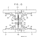
- FIG. 13 An expandable cleat or block 15 for varying the depth of the cavity in a dual walled partition, according to the present invention, is shown in Figure 13.
- the opening direction is shown by arrow A.
- the arrangement is a flush mounting of panels 2' and 2 and the carrying bars or posts 170.
- the hinges 20 are mounted as shown in Figure 1.
- the blocks 172 are slotted and receive an elongated slotted bar or link 174.
- Bolts 176 one through a bore in each block 172, extend through the slot in bar 174.
- the bolts 176 have threaded ends which receive nuts 178. When nuts 178 are loosened, the blocks 172 can be slid apart or together and positioned to create a preselected cavity depth or thickness, whereupon nuts 178 can be tightened.
- Figures 14A and 14B show another -technique for obtaining a variable cavity depth or thickness.
- the arrangement is a flush mounting like Figure 13.
- the cleats or blocks 15 are comprised of two sets or fixed blocks or sections 180, each demountably attached to carrying bars 170 in a known load bearing manner 171, such as by mutually cooperating hooks or screws and keyholes.
- Intermediate the blocks or sections 180 is a modular block 182 demountably attached to sets or fixed blocks 180 by dovetail joints.
- a plurality or series of modular blocks 182 of which two are shown as blocks 182, 182' enable the cavity thickness to be varied.
- Hinges 20 are carried in blocks 180 (permanent in the structure vs the changeable blocks 182).
- FIG. 15A and 15B An alternative technique for mounting hinge parts of hinges 20 in panels 2, 2' is shown in Figures 15A and 15B.
- a panel 2 is provided with a dovetail slot or groove 190 (Figure 15A) or T-slot or groove 200 (Figure 15B) on its inside face 192, originating from one of its edges 194.
- a hinge part 196 which could be a hinge cup 21, a hinge arm 22 or a mounting plate 23 is fixed to a curved metal plate 198 that slides into groove 190 and is held under friction or tension.
- a stop such as a set screw or pressure plate can be used to lock plate 198 in groove 190.
- a flat metal plate, strip or bar 202 slides into groove 200 and has fixed to it the hinge part 196.
- a lock or stop cooperates with plate 202 to retain it in groove 200.
- Plate 202 can also be adhesively fixed in groove 200.
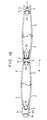
- Figure 16 shows an embodiment where the panels 2, 2' are maintained at shallow angles, preferably 5°-30°, when in the closed position, as shown in the drawing.
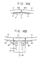
- the abutting edges 302, 302' of panels 2, 2' are beveled at angles such that in the closed position, they will approximate to the least gap or butt, as shown in Figure 16A.
- the trolleys are shown schematically as T and are mounted on top cleats 15.
- the terminal carrying posts 3 are shown at the left side of the figure and telescopically extend on either side of fixed jamb post 70 carrying the initiating abutments 134.
- Folding angles or arms 30 may be possibly omitted in this form of the invention because the shallow angles allow the panels to fold when the partition is pushed in the opening direction as indicated by arrow A.
- cleats 15 and carrying posts 3 are connected together to constitute a frame from which panels 2, 2' are carried by hinges 20.
- the connection between posts 170 and blocks 172 is shown schematically by reference number 171.
- the posts 170 carry the lower blocks 172. Therefore, the demountable coupling, if one is used in place of a fixed coupling, must be arranged to accommodate or satisfy the above requirements.
- top and/or bottom sweep strips that coact with the horizontal surfaces that define the upper and lower limits of the opening in which the folding partition is mounted.
- sweep strips 400, 401 which are segments attached respectively to the top and bottom edges of panels 2, 2' and carrying posts 3. Segments 401 overlap segments 400 at joints to secure isolation at these points.
- the sweeps on the bottom are more important because the tops of the panels and carrying posts already have seals cooperating with the board 55.
- the seals 400 are attached to the back lower edges of the panels and carrying posts.
Landscapes
- Engineering & Computer Science (AREA)
- Mechanical Engineering (AREA)
- Civil Engineering (AREA)
- Structural Engineering (AREA)
- Extensible Doors And Revolving Doors (AREA)
- Rigid Containers With Two Or More Constituent Elements (AREA)
- Carriages For Children, Sleds, And Other Hand-Operated Vehicles (AREA)
- Motorcycle And Bicycle Frame (AREA)
- Containers And Packaging Bodies Having A Special Means To Remove Contents (AREA)
- Seal Device For Vehicle (AREA)
- Air Bags (AREA)
- Hinges (AREA)
- Specific Sealing Or Ventilating Devices For Doors And Windows (AREA)
Abstract
Description
- This invention relates to a novel foldable partition which when extended lies flat substantially in a common plane, or in a shallow corrugation.
- Flat folding doors or walls are basically known from the following publications: Published German application 28 39 099; German Patent Specification 28 45 033; Published German Application 25 06 349; German Patent Specification 29 12 514; Published European Patent Application 0 111 9652; U.S. Patent 4,199,018; German Patent Publication 24 38 985; Published Patent Application 0 076 879; Published German Application 29 35 305; Published German Application 25 59 443;
German Patent Specification 16 83 191;German Patent Specification 11 57 757; German Utility Model 69 11 040; German Utility Model 78 27 705; Published European Patent Application 0 305 801. - In these known folding doors or walls, hinges are provided between carrying bars and panel elements. The hinges interconnect the panel elements but render the assembling of the doors or walls difficult and complicated and also complicate access to the folding door or wall for servicing or repairs.
- From US-A-4,867,221 a folding partition having two rows of spaced, pivotally associated rigid panels supported by a trackway or the like with a control mechanism providing movements of the panels from a flat-lined condition when the partition is in closed position to an open position in which the panels are oriented in opposed surface to surface stacked relation generally in perpendicular relation to the position of the panels when in closed position is known. The panels are respectively separated by intermediate strips. The hinge mechanism with this folding partition is complicated and therefore expensive. Furthermore, the hinge mechanism used is difficult to assemble and dismantle.
- The present invention therefore seeks to provide inexpensive hinge means for folding partitions, which can easily be assembled and dismantled.
- This object is achieved by a folding partition with the features of
claim 1. - The term "partition" in the present specification means door, wall partition and the like. The present invention provides a folding partition of the kind described, namely, one consisting of mutually opposite carrying bars, which are arranged in pairs and at their upper end portions are provided with bracket, which are displaceable in tracks fixed to the ceiling, have panel elements interposed between the carrying bars, which are hinged on one side to adjacent carrying bars and are hinged together on their other sides. Means are provided for pivotally moving the panel elements such that as they are pushed together from a closed position in which they lie flat substantially in a plane, the panels fold up into an open stacked position.
- It is, thus, the principal object of this invention to provide a novel structure for a folding partition which can be assembled, serviced and repaired in a much simpler and more expeditious manner than heretofore possible.
- Other objects and advantages of the present invention will become more readily apparent from the following detailed description of preferred embodiments when taken in conjunction with the appended drawings in which like parts have been designated by the same reference numerals.
-
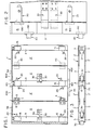
- Figure 1 is a view in elevation showing the inside surface of one side of a dual-walled partition shown in a closed, flat state;
- Figure 2 is an enlarged view showing a portion of Figure 1 to illustrate a hinge between a panel element and a carrying bar;
- Figure 3 is a top plan view showing both sides of the closed dual-walled partition shown in Figure 1;
- Figure 4 is a horizontal sectional view showing in larger scale the folding partition of Figure 3 as it is pushed to its open position at a time when two hingedly interconnected panel elements have already been moved to their folded or stacked position;
- Figure 5 is an enlarged fragmentary elevation showing a hinge between the two panel elements of Figure 1;
- Figure 6 is a vertical sectional view showing the hinge arrangement between two mutually opposite panel elements in an open or folded state;
- Figure 7 is a side elevation at the fixed side showing one end of the folding partition in an open state;
- Figure 8 is a top plan view of Figure 7;
- Figure 9 is an elevation similar to Figure 7 showing one end of the folding partition in a closed flat state;
- Figure 10 is a top plan view of Figure 9;
- Figure 11 is a detail of an alternative embodiment;
- Figure 12 is a detail of another alternative embodiment;
- Figure 13 is a horizontal section through a dual-walled partition showing an expandable cleat or block;
- Figures 14A and 14B are similar views as Figure 13 showing modular cleats or blocks to achieve a variable cavity depth;
- Figures 15A and 15B are details showing modifications for mounting hinge parts to panels or carrying posts;
- Figure 16 shows in top plan an alternative embodiment wherein panels lie at shallow angles when in the closed position; and
- Figures 16A and 16B show details of Figure 16.
- Referring now to the drawings, a detailed description of a preferred embodiment follows.
-
Folding partition 1 shown in the drawings consists of pairs of hingedly interconnected panel elements, 2, 2'. A pair ofhinges 4 interconnect the adjacent, juxtaposed edges ofrigid panel elements 2 and 2'. The pair ofhinges 4 are preferably of the loose pin type and secured to the inside ofpanels 2, 2' with onehinge plate 5 secured to panel 2' and theother plate 6 secured topanel 2. Theplates eyelets 8 and 9 that receive a loose, headedpin 12. Thepanel elements 2, 2' on their remote free edges are hingedly connected to adjacent carrying bars orposts 3. The pairs ofpanel elements 2, 2' and the intermediate carrying bars orposts 3 constitute one side of the partition which may be a wall or a door. Likepanel elements 2, 2' and associated carrying bars orposts 3 constitute the other side of thefolding partition 1 as will be apparent from Figure 3. - In accordance with Figures 1 and 3, the pairs of
panel elements 2, 2' are interconnected by so-called curled-uphinges 4 havingplatelike hinge parts fixing screws 7 to the inside surfaces ofrespective panel elements 2, 2' in the manner described such that the vertically spaced apart curled-up eyes are meshing and disposed in the gap between thepanel elements 2, 2'. Thehinge pin 12 is provided at its top with ahead 11 and extends with a clearance through the aligned bores of the curled-upeyes 8, 9, so thatpin 12 can be readily removed. To this end,top hinge 4 is spaced sufficiently below the top edge ofpanels 2, 2' thatpin 12 can be lifted vertically and removed fromeyelets 8,9. - Mutually opposite carrying bars or
posts 3 are mounted on or interconnected by an approximately rectangular block orcleat 15. The width of theblocks 15 approximately corresponds to the width of thecarrying bars 3 so that the narrow end faces 16, 17 of thecarrying bars 3 lie in a common plane with theoutside surfaces block 15, see Figure 4. For hingedly connecting thepanel elements 2, 2' to thecarrying bars 3, mutually opposite outer end faces of thecarrying bars 3 and of thecleats 15 are provided with milledrecesses 100, in which pivotally movable cup-shaped hinge parts 20' of double-link hinges 20 are held in the usual manner, e.g., the countersinkable cups 20' are provided withflangelike parts 21, which protrude over the rims of the milled recesses and are formed with bores through which fixingscrews 21 fasten hinges to block 15 andposts 3. The hinge arm orbracket 22 and itsmounting plate 23, fixed byscrews 23 topanel element 2 or 2', are connected by two links to the cup shaped hinge parts 20'. The double-link hinges 20 preferred in the present invention are of the kind made and sold by Salice America, Inc., of Charlotte, NC, especially the Salice 100, 200 or F, models C1A6, C2A7, C2A6, C2A9 and CFA7 equipped with DOMI®. rapid assembly mounting plates. Use of the DOMI®. automatic assembly enables the hinge to be attached and detached from the mounting plate with only slight pressure thereby facilitating quick attachments and detachment for assembly or repair. Other like hinges are commercially available, e.g.: from Juluis Blum Inc. of Stanley, N.C. under the trademark BLUM® "clip" concealed hinges. - The hingedly interconnected pairs of
panel elements 2, 2' of each side move in the direction A of the opening movement, see arrow in Figure 1 when opening the partition to its stacked condition. Folding brackets orangles 30, also referred to as actuator arms, are secured to the inside ofpanels 2 about their midpoint. Angle orinitiator arm 30 consists of a leg 30' which is connected byfixing screws 31 to thepanel element 2 equidistant from its vertical edges and aleg 32, which extends approximately at about 30° and aleg 33, which is a continuation ofleg 32. A bend 33' putsleg 33 at an angle to leg 30' of from 60° to preferably 90°.Leg 33 constitutes a deflector or pusher and during an opening movement will, through interaction with another element, exert a force on the associated panel element to which it is attached and which still lies in the closing plane to produce a buckling moment for initiating the desired folding action. Figure 4 shows the position at which thelegs 33 of thosepanel elements 2 which are still in their closed position strike against thelegs 33 of thepanel elements 2 which precede or lead them in the opening direction (see arrow A).Legs 33 of succeedingpanels 2 strike the nowstationary legs 33 of the next leading or precedingpanels 2 which have already been turned through about 90°. As a result, a buckling moment for initiating the folding is exerted on the next trailing or succeedingpanel elements 2, which are shown in Figure 4 still in their closed position. - The pairs of
panel elements 2, 2' of both sides are provided at their narrow end faces with longitudinally extending grooves orrecesses 40, in which slightly projectingsealing bars 41 are held.Bars 41 consist of elastomeric and/or plastically deformable material and protrude beyond the plane of the edge face. In the closed position shown on the right in Figure 4, sealing bars 41 bear with deformation on the opposite end face of a panel element or of a carrying bar so that a tight and also noise-insulating seal is effected. - Instead of so-called curled-up hinges 4, so-called Stabilo hinges, mortise concealed hinges, may be used to hingedly interconnect the
panel elements 2, 2'. Stabilo hinges consist of hinge cups, which are countersunk into the narrow end faces of the panel elements and held in by countersink screws or a wedge and are interconnected by hinge arms extending into such cups. Such hinges 110 are indicated by broken lines on the right in Figures 1 and 4. These hinges are also detachable and attachable for effecting assembly and repair by removing the countersunk screws or loosening the wedges and withdrawing the hinge cups. - The
cleats 15 which interconnect pairs of opposed carryingbars 3 are provided at the top with a trolley carrying freely rotatable, axle mountedrollers 51 with the axle mounted on trolley-carryingshanks 50. Therollers 51 roll on atrack 54, more specifically on flanges which form the rails oftrack 54 which are inwardly angled toward each other. Thetrack 54 is secured to a base 112 such as byscrews 114.Track 54 is covered on its outside surfaces by bars, boards orpanels 55. The inside surfaces of the carryingbars 3 and the outside surfaces of thebars 55 define narrow gaps, which are bridged by strip-shapedseals 57 of any suitable acoustical or sound absorbing material.Seals 57 can be secured to the inside surfaces of the carryingbars 3 or outside surface ofbars 55. Similarly, the inside surfaces of thepanel elements 2, 2' are provided with sealingstrips 58, see Figure 5, also of a suitable acoustical or sound absorbing material, which in the closed state of the door are also in sealing contact with the covering bars 55. These sealing strips will also avoid an occurrence of striking sounds when the folding door is closed at a higher extension speed. - It is apparent from Figures 1 and 2 that the folding angles 30 of each side of the door are arranged in vertically spaced apart horizontal planes in such a manner that during an opening movement of the folding door each
folding angle 30 will cooperate without conflict with the diagonally opposite foldingangle 30. It is also apparent from Figures 1 and 2 that the double-link hinges 20 provided on thecleats 15 or on the end faces of the carryingbars 3 are vertically spaced apart in horizontal planes in such a manner that thehinges 20 will not strike against each other as the folding door is opened so that the door can be more compactly folded as it is opened. - It is apparent from Figure 4 that an opening movement will impart to the
panel elements 2, 2' such an outward pivotal movement that in a folded stacked state they will overlie and their narrow edges will lie adjacent to the outside surfaces of the carrying bars 3. The design also promotes close folding within a small space during the opening movement. - Figure 4 shows in its bottom right-hand part a different embodiment of a seal in the gap between two panel elements. That seal consists of a
strip 60, which is made from known sound-proofing sealing material, such as a flexible plastic, and extends throughout the height of thepanel elements 2, 2'.Strip 60 at one of its edges is secured byscrews 61 to the inside surface of the one panel element 2'. As is illustrated, the sealingstrip 60 covers thesmall gap 62 between twopanel elements 2, 2'. The juxtaposedopposite panel element 2 is provided on the inside surface of its edge portion with a flat receiving slot, which is defined by inverted U shapedchannel members 63, which have been attached byscrew 64. As thehinge 110 is established, the freely protruding portion of the sealingstrip 60 is inserted into the slot that is formed by thechannel member 63, so that the sealingstrip 60 bridges and seals thegap 62, but themember 63 cooperates withstrip 60 to allow sliding relative movement. Such a gap seal will be desirable when hinges 110 are used which comprise hinge cups which are countersunk in the end faces of the panel elements and would hinder use of sealingstrip 41 in corresponding grooves or recesses 40. The freely protruding edge portions 60' of the sealing strips 60 are so long that they can be inserted into the slots before the hinge cups of thehinges 110 are inserted into the recesses and fixed by screws. - Figures 8 and 10 show the stationary stop bars or jamb post 70, which is fixed on the wall or the door post in the direction of the opening movement of the partition and which during an opening movement of the partition is telescopically straddled by the leading or terminal carrying bars or
posts 3, which are interconnected by thecleats 15. As is apparent from Figures 7 to 10 the terminal leading carryingbars 3 are extended beyond thecleats 15 toward the carrying wall to constitute forks, which can telescopically straddle the stop bar or jamb post 70 during the opening movement. - Layers or strips of known soundproofing material attached to the inside surfaces of the extended carrying bars will sealingly engage the planar outside surfaces of the
stop bar 70. As the folding door is opened and closed, the sealing strips 71 wipe on the outside surfaces of thestop bar 70 so that a seamless sealing joint to the carrying bars is established. - A threaded
closing stop 130 is fixed to thestop bar 70 and extends horizontally through a hole inlower cleat 15 terminating in ahead 132 substantially larger than the hole. Stop 130 is threaded to allow adjustment. When the partition moves from the open position, Figure 8, to the closed position, Figure 10, stop 130 andhead 132 limit travel of the firstlower cleat 15, as shown. Also, startingupset brackets 134 are horizontally aligned to be struck by the first pair ofangles 30 to initiate the opening sequence of the first pair ofpanels 2, 2'. - In a folding partition of the invention, the hinges between the
panel elements 2, 2' consist of furniture hinges, in particular, loose pin hinges. The use of furniture hinges known per se affords the great advantage that the assembling is simple and access for repairs or servicing is simple and easy. For instance, when a panel element of the partition in accordance with the invention has been damaged and must be replaced, it will be sufficient to disconnect readily thehinges 4 between two panel elements when the partition is open or even partially open simply by removingpins 12.Hinges 4 are then accessible because the panel elements have been pivotally moved through about 180 degrees (90° each) relative to each other from their closed position and are now juxtaposed approximately parallel to each other but horizontally spaced apart. When thehinges 4 between two panel elements have been disconnected, these panel elements can freely be swung out.Hinges 20 connected to the carryingbars 3 become also readily accessible and a replacement can easily be effected by disconnectinghinges 20 and removing the panel and substituting another. Repairs can be made also in the interior between the two sides of the partition since the cavity is fully accessible through the opening created by the swung out panels. - The
panel elements 2, 2' are suitably connected to the carryingbars 3 byhinges 20 having hinge parts which are pivotally movable relative to each other and are connected by two links in each hinge. Such hinges are usually called "cup hinges" because their pivotally movable hinge parts are cup-shaped and their two hinge parts together with the interconnected links constitute a four-bar linkage. Such hinges are known in various forms but the preferred hinges 20 are available from Salice America, Inc., as aforementioned. Reference is made to publications showing such hinge connections, e.g., to PublishedGerman Applications 31 19 571 and 36 24 237, which disclose such hinges with special designs of the means for fixing the hinge brackets. By such double-link hinges thepanel elements 2, 2' can be connected to the carryingbars 3 that when the folding door or wall is closed the panel elements and the carrying bars are disposed in one plane so that the narrow longitudinal sides or end faces of the carrying bars and panel elements are aligned and face each other with only a small clearance. The double-link hinges used in accordance with the invention are so secured to the inside surfaces of the carryingbars 3 andpanel elements 2, 2' that when the folding partition is closed, made flat, said carryingbars 3 orpanel elements 2, 2' lie in a common plane and owing to the motion characteristic of the four-bar linkage including the double links, thepanel elements 2, 2' will be lifted out during an opening movement of the partition and will so be moved relative to outside surfaces of the carryingbars 3 that the narrow longitudinal sidefaces of said panel elements, which narrow longitudinal sidefaces had been aligned with and face the narrow longitudinal sidefaces of the carryingbars 3, now retract behind the narrow longitudinal sidefaces of the carrying bars 3. This means that an opening movement of the partition will cause thepanel elements 2, 2' to be folded through almost 90° onto the outside surfaces of the carryingbars 3 so that the folding partition in an open state can be folded together into a compact, space-saving packet or stack. - Desirably, those hinge parts which are provided with hinge brackets are connected to the
panel elements 2, 2' and the other hinge parts, which in the usual use of the hinges as furniture hinges are the pivotally movable hinge parts, are connected to the carrying bars 3. In such an assembly the furniture hinges will assume their inherently closed position when the panel elements have been extended so that the partition is in its closed position. As a result, the double-link hinges of the folding door or wall in accordance with the invention are mounted in an unusual manner because the carryingbars 3 which are displaceable but are not pivotally movable, may be regarded as the stationary carrying parts, to which the pivotally movable hinge parts (cups) are secured, where as the hinge brackets (the hinge arm and mounting plate), which are usually stationary, are secured to thepanel elements 2, 2', which are pivotally movable relative to the carrying bars 3. - The other hinge parts desirably consist of cup-shaped hinge parts, which are adapted to be countersunk and are held in milled recesses formed in the narrow end faces of the carrying
pars 3 and/or thecleats 15 which interconnect said carrying bars in pairs. The upper andlower cleats 15 together with thebars 3 constitute a frame suspended fromtrack 54 by a trolley attached to thetop cleat 15. The frame supports and carries thepanels 2, 2' by means of hinges 20. - In a particularly desirable embodiment the hinges or
brackets 20 are adapted to be connected by quick disconnectable snap joints to carryingplates 23 which are part of thehinge 20. Theplates 23 are secured to thepanel elements 2, 2'. Such snap joints between the hinge brackets and carrying plates are known, e.g., from the following publications: Published European Patent Application 348 656; Published European Patent Application 225 609; Published European Patent Application 43 903. It is particularly desirable to connect the hinge brackets to thepanel elements 2, 2' by releasable snap joints, which are adapted to be established in that hooking members are hooked in and the hinge arm or bracket is pivotally moved. Thepanel elements 2, 2' which are held by such so-called clip or cup joints can be quickly disconnected and unhooked at the hinges by a simple actuation and can be similarly hooked in. The preferred hinges 20, as previously noted, use the DOMI® rapid assembly mounting plates with automatic coupling. DOMI® is a trademark of Arturo Salice Sp.A. of Novedrate, Italy. - In accordance with a further desirable feature at least some of the
hinges 20 provided on at least one side (preferably panel 2') of a pair of hingedlyinterconnected panel elements 2, 2' are provided with a spring, which is effective adjacent to the closed position and tends to hold thehinge 20 in its closed position. Such hinges are known, e.g., fromGerman Patent Specification 31 16 825. In response to the closing moment, said hinges 20 will ensure that thepanel elements 2, 2' and carryingbars 3 will be aligned in a common plane (lie flat) when the folding partition is closed because the closed position in which the panels and carrying bars lie in one plane corresponds to the closed position in which the hinges are held by spring action. The most preferred form is that thelower hinge 20 on panel 2' be fitted with a spring and the other three hinges 20 (the top one on panel 2' and the two on panel 2) not be fitted with a spring. - In accordance with a further desirable feature of the invention the hinge parts of those hinges which interconnect the
panel elements 2, 2' are so countersunk in milled recesses in the narrow longitudinal side faces of said panel elements that the panel elements are aligned and abut in the closed position. Hinges which can be used for such a joint are offered, e.g., by Hafele KG in Nagold, West Germany as Stabilo hinges under the Order No. 341.25.516. The two hinge parts which are held in milled recesses are provided with countersinkable flangelike retaining parts, which are provided with bores for retaining countersunk head screws acting on wedges, which can be loosened, to disconnect the hinges whenpanels 2, 2' are folded together so that thepanel elements 2, 2' can be pivotally moved apart and the other hinges 20 connecting thepanel elements 2, 2' to the carryingbars 3 are rendered accessible. - In another embodiment the hinges interconnecting the panel elements consist of so-called curled-up hinges (loose pin hinges 4), which comprise hinge plates that carry curled-up eyes and are screw-connected to the inside surfaces of the
panel elements 2, 2'. The hinge pins 12 of said hinges extend through the aligned eyes and are provided with atop head 11 and are held in and adapted to be lifted out of the eyes. Such curled-up hinges are known and are offered, e.g., by Hafele KG in Nagold, West Germany under Order No. 354.13.944. Such hinges afford the advantage that it is not necessary to unscrew a hinge part when the hinges between the panel elements are to be disconnected. It is sufficient to lift upwardly thehinge pin 12, which is held in the eyes with a clearance, in order to disconnect the hinge. The hinge can be re-established just as easily. This is the preferred form. - Desirably, the
hinge brackets 20 for hingedly connecting thepanel elements 2, 2' to the carryingbars 3 of each side are arranged in vertically spaced apart horizontal planes. That design ensures that the hinge brackets of consecutive carrying bars will not strike against each other in the closed position so that a closer folding in the open position can be achieved. - In accordance with another particularly desirable feature, for which protection is claimed per se, the means for pivotally moving the
panel elements 2, 2' consist of folding angles or initiatingarms 30, one leg of each of said angles is connected to thosepanel elements 2 of each pair which lead in the direction of the opening movement. End deflectors angled from said legs are disposed adjacent to the carryingbars 3, and the folding angles 30 are so arranged in at least two vertically spaced part, horizontal planes that diagonally opposite ones which are consecutively arranged in a plane and associated with respective sides cooperate without conflict. When the door or wall is being opened said folding angles 30 will cause a folding of each of those outer pairs ofpanel elements 2 which lead in the direction of the opening movement so that consecutive folding operations will orderly be performed at the end of the opening side. - In such an arrangement only the pairs of panel elements 2' which trail in the direction of the folding movement are desirably connected to the succeeding carrying
bars 3 byhinges 20 having a spring-biased snap action so that the leading hinges 20 can be folded more easily without an opposing torque as the buckling moment is introduced into said hinges 20 by means of the folding angles 30. - In accordance with a further particularly desirable feature the
track 54 provided on the ceiling is covered on both sides by bars orboards 55 and the spacing of the outside surface of the covering bars 55 corresponds to the spacing of the inside surfaces of the carryingbars 3 and thepanel elements 2, 2' in a closed state. Because thespecial hinges panel elements 2, 2' to each other and to the carryingbars 3 in the folding partition in accordance with the invention have the result that thepanel elements 2, 2' and carryingbars 3 will lie in a plane (flat) in the closed state, the gaps between thebars 55 which cover the track and the inside surfaces of the carryingbars 3 andpanel elements 2, 2' may be made so small that they virtually contact each other. Strips of known sealing and sound-proofingmaterial 57 may be secured to the top end portions of the carryingbars 3 andpanel elements 2, 2' and will provide an additional sealing action. Said strips of sealing material serve particularly also for sound insulation. - In accordance with a further particularly desirable feature, profiled sealing bars 41 made of elastomeric and/or plastically deformable material are inserted in
grooves 40 in the narrow side faces of thepanel elements 2, 2' on at least one side or edge. When the folding partition is closed, said sealing bars 41 are disposed between and seal the narrow end faces which face each other and said sealing bars serve particularly for sound insulation. - Because the
panel elements 2, 2' can easily be replaced they may be provided with inserts of transparent material or glass because when apanel 2 or 2' has been destroyed or damaged a corresponding panel element can easily and quickly be substituted as a replacement. - For each of the described preferred embodiments and features of the invention, also as far as dependent claims are directed to them, independent protection is claimed. Respective alteration of the claims is reserved.
- Another preferred embodiment for which independent protection is claimed provides a one-sided flat foldable partition consisting of carrying
bars 3, plate or bar-shapedpanel elements 2, 2' which are hinged to carryingbars 3 and are hingedly connected on their narrow longitudinal side faces which face away from the carryingbars 3 and angles 30 for pivotally moving the panel elements as they are pushed together from a closed position in which they lay substantially in a common plane. The hinges 20 between the carryingbars 3 and thepanel elements 2, 2' and thehinges 4 between thepanel elements 2, 2' consist of furniture hinges mounted in vertically spaced relations without conflict. For this one-sided foldable partition all previously described preferred embodiments and features can be used as far as they relate only to one side of the foldable partition. The one-sided foldable partition preferably can be used as a closure or door for cupboards or the like. - A special feature of the furniture hinges used in the described invention is that they are readily separable. A further feature of the hinges is that they have a relatively small height and are able to be readily disengaged. The hinges may be mounted traditionally, that is, according to usual instructions but also can be mounted reversely as in the case of
hinges 20 as described. - Furtheron the panel elements and the carrying bars of each side of the dual walled partition may be arranged in such a way that they in the closed position are not in the same plane.
- Furtheron it is desirable that the vertical seals between the
bars 3 andpanels 2, 2' and between thepanels 2, 2' are separate structure from the hinges so that the seals only serve as seals and not also as hinges. - Seals may serve to reduce sound transmission through flanking paths between
track 54 andpanels 2, 2'. Seals may be horizontal intermittent seals on the panels and/or carryingbars 3 or may be on thebars 55 or partially on each, the important point being good sealing and sound insulation. - Carrying
bars 3 can be in the same plane withpanels 2, 2' or behind them to achieve "board and batten" effect. This is readily accomplished by appropriate selection of known hinges 20 to achieve this result. In place of mounting hinges 20 in reverse fashion, the cup hinges 20 can be mounted in the traditional way with the cups in thepanels 2, 2'. - Horizontal seals can be under the track or track mould rather than on the back of the panel and/or carrying
bars 3. - As an alternative to the
panels 2, 2' of the foldable partition being in the same plane as the carryingbars 3, thepanels 2, 2' could be arranged to overlay the carrying bars in "half overlay or twin" application. In this alternative, the clearance between the edges of the panels could be made as small as possible for minimal reveal. The clearance also could be increased to create "board and batten" reveal effect. The reveal can be in matching color or contrasting to create a decorative reveal. This arrangement allows seals to be placed on the back of the panels or on the face of the battens rather than on the edges of the panels or battens. The edges of the panels can be shaped or profiled in any decorative shape (e.g. rounded). - If in the just described alternative, minimal clearance is used, then the stack depth is minimized and battens or carrying
bars 3 as appearance elements are eliminated. The foldable partition can be offered to users with no reveal or with board and batten. There is the choice between matching or contrasting reveals and the edge shapes can be varied. - Glass doors may consist of glass panels connected by cup hinges 20. A number of different models of
hinges 20 are available from Salice America, Inc. that are suitable for this purpose. - To make the door or wall almost fireproof, the
panels 2, 2' may consist of calcium silicate boards which may have a thickness of approximately 8 mm which would give approximately a two-hour fire rating. With appropriate gasketing material the door could have a two- or three-hour fire rating. Intumescent or mineral fiber material can be used to create a fiber blanket or fire seal as is well known in the art for this purpose and these materials are readily commercially available. - When thin panels (e.g. 8-10 mm) are used, hinges 20 cannot be screwed to the back of the
panels 2, 2'. For mounting thehinges 20, routing grooves on the backs of the panels may be provided which may have a dovetail or T-profile, see Figures 15A and 15B. The mounting plate or carrying arm of the hinge then may be slipped into the groove and tightened by pressure screws or cupped for friction. - Acoustical performance of the panels may be improved by using various materials, thicknesses, sounddampening liners and sound absorption liners. Acoustical performance of the flat folding partition can be further improved by increasing thickness of partition (cavity). Thickness of cavity could be varied by having coupling elements (cleats 15) between pairs of carrying
bars 3 that would be adjustable in width or modular. The preferred size of cavity is between 3 and 6 inches to obtain the best sound insulating properties consistent with all other requirements. - Acoustical performance can be further improved by resiliently de-coupling the pairs of carrying
bars 3. This can be accomplished by e.g. minimizing the number of coupling elements and using elastomeric material in their joining. - The coupling elements (cleats 15) can be made e.g. of molded plastic ready to receive the cup hinges and to slip fit onto the backs of carrying
bars 3 by keyholes or the like. - Acoustical performance can be further enhanced by resiliently isolating each
panel 2, 2' from itsadjacent carrying bar 3 orpanel 2, 2' e.g. by gasketing or sealing under cup hinges. Preferably acoustical seals should be made of extruded PVC or closed cell plastic material. - The
top track 54 could consist of extruded material to receive the backs of the panels without requiring wood strips 55. Gaskets or seals could be put into the face of the track to avoid segmenting them on the backs of thepanels 2, 2'. Optionally, magnetic extruded seals could be used, if thetracks 54 are of a magnetic receptive material, e.g. steel. - Bottom sweep seals may be added and secured to the bottom of
panels 2, 2' and bars 3, see Figure 1. They could be segmented and may be arranged overlaying and adjustable to give full coverage across the bottom of the door. Sweep seals may also be used at the top of the door. - By making the panels wider and thinner very wide openings may be provided with minimum stack depth.
- The present invention enables a door with high acoustical and fire performance to be made due to the fact that the joints between the
panels 2, 2' are very narrow and can be sealed effectively. Also, the cavity can be made thicker because the door extends flat. - It is possible to eliminate the carrying
bars 3 and any spacing between adjacent pairs ofpanels 2, 2'. The hinges 20 can be fastened together, back-to-back, so that thepanel 2 of one pair is directly adjacent the panel 2' of the next leading or preceding pair. The cup portions of thehinges 20 which are connected together, are either connected to cleat 15 or to the pair ofhinges 20 on the opposite side. A yoke or frame would be attached to thetrolley 50 carryingrollers 51 which in turn is suspended fromtrack 54. The frame could include block orcleats 15 or not. Hinges 20, coupled as noted, would be mounted to the frame and carried thereby. Spacers could be interposed between thehinges 20 and frame to achieve the desired cavity. The frame would have clearance for the angles orarms 30 to permit their action and function as previously described. - Figure 11 shows a detail of an alternative embodiment.
Block 150 is the same ascleat 15, that is, rectangular and of limited dimensions. There is an upper block 150 (not shown) and lower block 150 (shown).Blocks 150 are tied together by a fullheight aluminum extrusion 152 that is anchored on both sides in eachblock 150 bybarbs 154 integral withextrusion 152.Seals 156 are provided on the face ofextrusion 152.Blocks 150 extend across the cavity and are tied together on the other side by an extrusion 152 (not shown) in the same way.Top block 150 has atrolley 50 mounted on it to suspend the frame formed byblocks 150 andextrusions 152 from anoverhead track 54. Pairs ofpanels 2, 2' are carried byblock 150 and the next trailing block 150 (not shown) by hinges 20. The opening movement is shown by arrow A. - Panel 2' of a leading pair of
panels 2, 2' is mounted to the left side ofblock 150 byhinge 20 withhinge cup 21 mounted in panel 2' and hingearm 22 and its associated mounting plate mounted onblock 150. Asecond hinge 20 similarly mountspanel 2 of the next trailing pair ofpanels 2, 2' to the right side ofblock 150. The mounting is of the half overlay type with asmall reveal 158 between thepanels 2' and 2. - Figure 12 shows a detail of another embodiment. A
block 160 extends across the partition cavity top and bottom (only one being shown), likecleats 15. Boards or bars 162 extend full height on both sides ofblocks 160 and are fastened toblocks 160. Like Figure 11, hinges 20mount panels 2' and 2 to block 160. In this embodiment, the partition mounting is flush with small reveals orgrooves 164, which can be minimized. - An essential point of the invention resides in the separability of the elements for easy manufacture, assembly, installation, repair, acoustical performance and fire performance.
- An expandable cleat or block 15 for varying the depth of the cavity in a dual walled partition, according to the present invention, is shown in Figure 13. The opening direction is shown by arrow A. The arrangement is a flush mounting of
panels 2' and 2 and the carrying bars or posts 170. The hinges 20 are mounted as shown in Figure 1. - The
cleat 15 is composed of twoblocks 172, each of which is quickly detachably connected in a known load bearing manner as indicated byreference number 171 to one of thebars 170.Cups 21 ofhinges 20 are recessed intoblocks 172 in known manner.Hinge arms 22 are attached to the inside ofpanels 2', 2 in known manner. - The
blocks 172 are slotted and receive an elongated slotted bar or link 174.Bolts 176, one through a bore in eachblock 172, extend through the slot inbar 174. Thebolts 176 have threaded ends which receive nuts 178. Whennuts 178 are loosened, theblocks 172 can be slid apart or together and positioned to create a preselected cavity depth or thickness, whereuponnuts 178 can be tightened. - Figures 14A and 14B show another -technique for obtaining a variable cavity depth or thickness. The arrangement is a flush mounting like Figure 13. As shown the cleats or blocks 15 are comprised of two sets or fixed blocks or
sections 180, each demountably attached to carryingbars 170 in a knownload bearing manner 171, such as by mutually cooperating hooks or screws and keyholes. Intermediate the blocks orsections 180 is amodular block 182 demountably attached to sets or fixedblocks 180 by dovetail joints. A plurality or series ofmodular blocks 182 of which two are shown asblocks 182, 182' enable the cavity thickness to be varied.Hinges 20 are carried in blocks 180 (permanent in the structure vs the changeable blocks 182). - An alternative technique for mounting hinge parts of
hinges 20 inpanels 2, 2' is shown in Figures 15A and 15B. Apanel 2 is provided with a dovetail slot or groove 190 (Figure 15A) or T-slot or groove 200 (Figure 15B) on itsinside face 192, originating from one of itsedges 194. Ahinge part 196 which could be ahinge cup 21, ahinge arm 22 or a mountingplate 23 is fixed to acurved metal plate 198 that slides intogroove 190 and is held under friction or tension. If desired, a stop such as a set screw or pressure plate can be used to lockplate 198 ingroove 190. - A flat metal plate, strip or bar 202 slides into
groove 200 and has fixed to it thehinge part 196. A lock or stop cooperates withplate 202 to retain it ingroove 200.Plate 202 can also be adhesively fixed ingroove 200. - Figure 16 shows an embodiment where the
panels 2, 2' are maintained at shallow angles, preferably 5°-30°, when in the closed position, as shown in the drawing. The abutting edges 302, 302' ofpanels 2, 2' are beveled at angles such that in the closed position, they will approximate to the least gap or butt, as shown in Figure 16A. The trolleys are shown schematically as T and are mounted ontop cleats 15. Theterminal carrying posts 3 are shown at the left side of the figure and telescopically extend on either side of fixed jamb post 70 carrying the initiatingabutments 134. For convenience not all cup hinges 20 are shown. Folding angles orarms 30 may be possibly omitted in this form of the invention because the shallow angles allow the panels to fold when the partition is pushed in the opening direction as indicated by arrow A. - As shown in Figure 16B, the cup hinges 20 are mounted with
cups 21 angulated with respect to the transverse axis or plane of the partition throughcleat 15. As shown, thecups 21 lie at a shallow angle, preferably from about 5° to about 30° relative to the transverse axis TA of the partition through thecleat 15. Thecups 21 are turned outwardly to establish the shallow angle ofpanels 2, 2'. - Acoustic isolation of the two sides of a dual-walled partition according to the present invention can be achieved by interposing resilient or non-resilient sound damping material in any of the joints, e.g., between carrying posts-3 and
cleats 15 or within thecleat 15 structure as shown in Figures 13, 14A and 14B. In Figure 13, resilient material can surround and encase the slottedbar 174 to isolate it fromblocks 172 and resilient material can surroundbolts 176 to isolate them fromblocks 172 andbar 174. Similarly, in Figures 14A and 14B, the joints between fixed or set blocks 180 (fixed or set dimensionally) andmodular block 182 can include resilient material that sound isolates. Gasketing in this fashion will isolate one side of a dual-walled partition from the other. Controlling cavity depth or thickness will enable excellent sound absorbing or attenuation to be attained. - As previously noted,
cleats 15 and carryingposts 3 are connected together to constitute a frame from whichpanels 2, 2' are carried by hinges 20. In Figure 13, the connection betweenposts 170 and blocks 172 is shown schematically byreference number 171. Thetop cleat 15, which is attached to the trolley T that hangs fromtrack 54, suspends or carries theposts 170. In turn, theposts 170 carry the lower blocks 172. Therefore, the demountable coupling, if one is used in place of a fixed coupling, must be arranged to accommodate or satisfy the above requirements. - In addition to the above, sound isolation or proofing can be improved by using top and/or bottom sweep strips that coact with the horizontal surfaces that define the upper and lower limits of the opening in which the folding partition is mounted. Shown schematically in Figure 1 are
sweep strips panels 2, 2' and carryingposts 3.Segments 401overlap segments 400 at joints to secure isolation at these points. The sweeps on the bottom are more important because the tops of the panels and carrying posts already have seals cooperating with theboard 55. Theseals 400 are attached to the back lower edges of the panels and carrying posts. - Although the invention has been described in terms of specific and preferred embodiments, nevertheless, changes and modifications will be apparent to those skilled in the art which do not depart from the scope of the appended claims.
Claims (19)
- A folding partition foldable between an extended, unstacked state and a compact, stacked state comprised of a plurality of vertical carrying posts (3), roller means (51), mounted on the carrying posts (3) for supporting the carrying posts from a horizontal track (54), a plurality of vertical panels (2, 2') arranged in adjacent pairs, each panel (2, 2') having two vertical edges, panel supporting hinges (20) pivotally connecting one vertical edge of each panel (2, 2') of a pair of adjacent panels (2, 2') to a respective carrying post (3), panel connecting hinges (4) pivotally connecting the other adjacent vertical edges of said pair of adjacent panels (2, 2') together, and means (30) for initiating pivotal movement of the panels (2, 2'), as they are moved from the extended, unstacked state, in which they lie in substantially edge-to-edge relationship,
characterized in thatsaid panel supporting hinges (20) are cup hinges comprising a hinge cup (20') and a hinge arm (22) which are connected by link means and are pivotally moveable relative to each other between a closed position and an open position,the panel supporting hinge (20) is in its closed position, when the folding partition is in its extended, unstacked state, and the panel supporting hinge (20) is in an open position, when the folding partition is in a stacked state,the hinge being mounted in the corner defined by an edge of the post (3) and the inside face of the panel (2, 2'), when the partition is in the extended position, each of the hinge cup (20') and the hinge arm (22) being connected to one of each of these faces. - A folding partition as defined in claim 1, wherein said panel supporting hinges (20) have a relatively small height in relation to the height of said partition and allow said panel (2,2') to be readily disconnected from said carrying post (3).
- A folding partition as defined in claim 1, wherein said panel supporting hinges (20) have hinge parts which are pivotally moveable relative to each other and are connected by two links.
- A folding partition as defined in claim 1, wherein said cup hinges (20) have their said hinge arms (22) mounted on said carrying posts (3) for non-pivotal movement and have their said hinge cups (20') mounted in said panels (2,2') for pivotal movement.
- A folding partition as defined in claim 4, wherein said cup hinges (20) include mounting plates secured to said carrying posts (3) and said hinge arms (22) are connected by disconnectable snap joints to said mounting plates.
- A folding partition as defined in claim 1, wherein said cup hinges (20) have their said hinge cups (20') mounted in said carrying post (3) for non-pivotal movement and have their said hinge arms (22) mounted on said panels (2,2') or pivotal movement.
- A folding partition as defined in claim 6, wherein said cup hinges (20) include mounting plates secured to said panel (2,2') and said hinge arms (22) are connected by disconnectable snap joints to said mounting plates.
- A folding partition as defined in claim 1, wherein said panels (2,2') are relatively thin and mounting means are provided for connecting said panel supporting hinges (20) and/or said panel connecting hinges (4) to the backs of said panels (2,2') without penetrating into said panels (2,2') by screws
- A folding partition as defined in claim 8, wherein said mounting means is comprised of shallow dovetail or T-profiled grooves (190) routed into the backs of said panels (2,2') and specially adapted mounting plates received in said grooves.
- A folding partition as defined in claim 1, wherein at least one of said panel supporting hinges (20) associated with each of said pair of panels (2,2') is provided with a spring which is effective adjacent to the closed position and tends to hold said panel supporting hinge (20) in its closed position and said pair of panels in their extended, unstacked state.
- A folding partition as defined in claim 1, wherein said panel connecting hinges (4) have a relatively small height in relation to the height of said partition and allow said panels (2,2') to be readily disconnected from each other.
- A folding partition as defined in claim 1, wherein each of said carrying posts (3) is comprised of two vertical carrying post face elements having substantially the same height as the height of said partition and a plurality of carrying post joining elements which are of relatively small height and which connect the two carrying post face elements to each other, said carrying post joining elements being adapted to receive said panel supporting hinges (20) and in the case of the topmost joining element on each carrying post (3), adapted to receive said roller means (51).
- A folding partition as defined in claim 12, wherein said partition is dual-walled and said carrying post joining elements are adapted to be adjustable in width or modular in order to vary the thickness of the partition cavity.
- A folding partition as defined in claim 12, wherein said partition dual-walled and said carrying post joining elements are adapted to resiliently decouple the two walls (2,2,2',2') of the partition from each other.
- A folding partition as defined in claim 12, wherein when said partition is in its closed position the faces of the panels (2,2') and the faces of the carrying post face elements are in the same plane thereby giving the closed partition a substantially flat wall appearance.
- A folding partition as defined in claim 12, wherein when the partition is in its closed position panels (2,2') overlie the carrying post face element in adjacent vertical planes.
- A folding partition as defined in claim 1, wherein the vertical gap between each panel (2,2') and the carrying post (3) to which it is connected is sealed by a vertical carrying post seal when the panels (2,2') are in the extended, unstacked state, said vertical carrying post seal having a height substantially the same as the height of said partition and being so arranged that is seals but does not connect said panel (2,2') and said carrying post (3) to each other, the connection being accomplished only by said panel supporting hinges (20).
- A folding partition as defined in claim 1, wherein the vertical gap between the panels (2,2') in each pair of panels (2,2') is sealed by a vertical panel seal when the panel (2,2') are in the extended, unstacked state, said vertical panel seal having a height substantially the same as the height of said partition and being so arranged that it seals but does not connect said panels (2,2') to each other, the connection being accomplished only by said panel connecting hinges (20).
- A folding partition as defined in claim 1, wherein each of said pairs of panels (2,2') of said partition consists of a lead panel which leads in the opening direction and a trail panel which trails in the opening direction and said means for initiating pivotal movement of said panels (2,2') is comprised of at least one actuator arrm (30) connected to the back of each lead panel of said partition, each actuator arm (30) including an actuating portion disposed in the zone of the carrying post (3) to which said lead panel is connected.
Applications Claiming Priority (5)
| Application Number | Priority Date | Filing Date | Title |
|---|---|---|---|
| DE9000231U | 1990-01-10 | ||
| DE9000231U DE9000231U1 (en) | 1990-01-10 | 1990-01-10 | Folding door or folding wall |
| DE9005382U DE9005382U1 (en) | 1990-05-11 | 1990-05-11 | Double-shell, folding door or wall |
| DE9005382U | 1990-05-11 | ||
| PCT/US1991/000033 WO1991010802A1 (en) | 1990-01-10 | 1991-01-10 | Foldable partition |
Publications (3)
| Publication Number | Publication Date |
|---|---|
| EP0510044A1 EP0510044A1 (en) | 1992-10-28 |
| EP0510044A4 EP0510044A4 (en) | 1993-06-02 |
| EP0510044B1 true EP0510044B1 (en) | 1997-04-09 |
Family
ID=25956064
Family Applications (1)
| Application Number | Title | Priority Date | Filing Date |
|---|---|---|---|
| EP91902059A Expired - Lifetime EP0510044B1 (en) | 1990-01-10 | 1991-01-10 | Foldable partition |
Country Status (8)
| Country | Link |
|---|---|
| US (1) | US5411072A (en) |
| EP (1) | EP0510044B1 (en) |
| AU (1) | AU652350B2 (en) |
| CA (1) | CA2073435C (en) |
| DE (1) | DE69125596T2 (en) |
| ES (1) | ES2100224T3 (en) |
| NO (1) | NO302133B1 (en) |
| WO (1) | WO1991010802A1 (en) |
Families Citing this family (23)
| Publication number | Priority date | Publication date | Assignee | Title |
|---|---|---|---|---|
| AUPR480701A0 (en) * | 2001-05-04 | 2001-05-31 | Centor Products Pty Ltd | A lockable carrier hinge assembly |
| AU2003226075B2 (en) * | 2002-04-12 | 2008-09-25 | Instrumentation Laboratory Company | Immunoassay probe |
| US7228597B2 (en) * | 2002-04-23 | 2007-06-12 | Gerali Custom Design, Inc. | Partition apparatus and hinge apparatus |
| US7394860B2 (en) * | 2002-10-02 | 2008-07-01 | Nortel Networks Limited | Combined space-time decoding |
| US20060026798A1 (en) * | 2002-10-02 | 2006-02-09 | Gerali David A | Partition apparatus and hinge apparatus |
| US7114303B2 (en) | 2002-11-15 | 2006-10-03 | 3M Innovative Properties Company | Cover assembly for a through-penetration |
| US8211386B2 (en) | 2004-06-08 | 2012-07-03 | Biokit, S.A. | Tapered cuvette and method of collecting magnetic particles |
| MXPA06003796A (en) * | 2006-04-05 | 2007-10-04 | Jorge Casanova Arevalo | Versatile furniture and method for assembling the same. |
| US7874341B2 (en) | 2006-06-21 | 2011-01-25 | Won-Door Corporation | Hinged connection, movable partitions using same and related methods |
| US7931067B2 (en) * | 2006-11-03 | 2011-04-26 | Won-Door Corporation | Movable partitions with lateral restraint devices and related methods |
| US8087444B2 (en) | 2006-11-03 | 2012-01-03 | Won-Door Corporation | Movable partitions with lateral restraint devices and related methods |
| US7740046B2 (en) | 2007-04-27 | 2010-06-22 | Won-Door Corporation | Method, apparatus and system for controlling a movable partition |
| US7926538B2 (en) * | 2007-01-11 | 2011-04-19 | Won-Door Corporation | Lateral restraint for a movable partition, movable partitions incorporating same and related methods |
| US7854248B2 (en) * | 2007-03-29 | 2010-12-21 | Won-Door Corporation | Vision panel for movable partition, movable partitions and related methods |
| US8051616B2 (en) | 2009-06-02 | 2011-11-08 | Won-Door Corporation | Movable partitions, header assemblies for movable partitions, and related methods |
| US8316914B2 (en) * | 2009-07-28 | 2012-11-27 | Won-Door Corporation | Movable partitions, header assemblies for movable partitions, and methods of forming header assemblies for movable partitions |
| US8100164B2 (en) * | 2009-08-17 | 2012-01-24 | Won-Door Corporation | Movable partition systems including intumescent material and methods of controlling and directing intumescent material around the perimeter of a movable partition system |
| US8327591B2 (en) * | 2010-03-24 | 2012-12-11 | Wilkinson Jr Edgar L | Overhead panel and installation system |
| US9074420B2 (en) | 2011-05-31 | 2015-07-07 | Won-Door Corporation | Methods, apparatuses, and systems for resisting lateral displacement of movable partitions |
| US8960257B2 (en) | 2011-05-31 | 2015-02-24 | Won-Door Corporation | Methods, apparatuses, and systems for controlling lateral displacement of a movable partition |
| US9476248B2 (en) | 2011-11-28 | 2016-10-25 | Won-Door Corporation | Movable partition systems including header assemblies and related methods |
| US8613167B2 (en) | 2012-01-20 | 2013-12-24 | International Business Machines Corporation | Wall assembly system |
| MX2023005615A (en) | 2020-11-13 | 2023-05-29 | Armstrong World Ind Inc | ROOF SYSTEM WITH JOINT. |
Family Cites Families (15)
| Publication number | Priority date | Publication date | Assignee | Title |
|---|---|---|---|---|
| US3481388A (en) * | 1968-04-25 | 1969-12-02 | Won Door Corp The | Insulated door construction |
| US3799237A (en) * | 1971-02-27 | 1974-03-26 | I Proserpi | Folding door construction |
| US3672424A (en) * | 1971-03-03 | 1972-06-27 | Ram Partitions Ltd | Movable partition wall |
| DE2438985C2 (en) * | 1974-08-14 | 1976-08-19 | Hueppe Justin Fa | Double-shell folding wall or folding door made of panel-shaped elements |
| DE2652183C3 (en) * | 1976-11-16 | 1979-08-30 | Adolf Hirschel | Folding wall suspended from a room ceiling so that it can be moved |
| US4199018A (en) * | 1978-01-26 | 1980-04-22 | Horst Bohm | Folding partition shiftably suspended from a ceiling |
| NL190790C (en) * | 1980-04-15 | 1994-08-16 | Pella Bv | Folding wall. |
| IT1130738B (en) * | 1980-05-23 | 1986-06-18 | Salice Arturo Spa | IMPROVED DEVICE FOR CLOSING A HINGE IN PARTICULAR FOR FURNITURE |
| DE3119571A1 (en) * | 1981-05-16 | 1982-12-16 | Karl Lautenschläger KG, Möbelbeschlagfabrik, 6107 Reinheim | Furniture hinge |
| NL8204792A (en) * | 1982-12-10 | 1984-07-02 | Pella Bv | FOLDABLE SEPARATION. |
| US4658878A (en) * | 1985-12-16 | 1987-04-21 | Hough Manufacturing Corporation | Acoustic type folding door with separate cover sections |
| US4867221A (en) * | 1987-08-27 | 1989-09-19 | Panelfold, Inc. | Flat folding partition |
| US4848436A (en) * | 1987-09-22 | 1989-07-18 | Robert Dagenais | Folding access door in a foldable closure assembly |
| NL8800936A (en) * | 1988-04-11 | 1989-11-01 | Pella Bv | PARTITION WALL CONTAINING DOUBLE-WALLED PANELS JOINTED TOGETHER. |
| DE3841405A1 (en) * | 1988-06-29 | 1990-01-04 | Salice Arturo Spa | HINGED ARM WITH A FASTENING PLATE THAT FASTENS TO A FURNITURE PART OR THE LIKE. |
-
1991
- 1991-01-10 CA CA002073435A patent/CA2073435C/en not_active Expired - Fee Related
- 1991-01-10 EP EP91902059A patent/EP0510044B1/en not_active Expired - Lifetime
- 1991-01-10 WO PCT/US1991/000033 patent/WO1991010802A1/en not_active Ceased
- 1991-01-10 AU AU71636/91A patent/AU652350B2/en not_active Ceased
- 1991-01-10 ES ES91902059T patent/ES2100224T3/en not_active Expired - Fee Related
- 1991-01-10 US US08/214,669 patent/US5411072A/en not_active Expired - Lifetime
- 1991-01-10 DE DE69125596T patent/DE69125596T2/en not_active Expired - Fee Related
-
1992
- 1992-07-09 NO NO922707A patent/NO302133B1/en unknown
Also Published As
| Publication number | Publication date |
|---|---|
| US5411072A (en) | 1995-05-02 |
| CA2073435C (en) | 2001-04-03 |
| EP0510044A1 (en) | 1992-10-28 |
| AU652350B2 (en) | 1994-08-25 |
| WO1991010802A1 (en) | 1991-07-25 |
| AU7163691A (en) | 1991-08-05 |
| CA2073435A1 (en) | 1991-07-11 |
| NO922707L (en) | 1992-09-07 |
| DE69125596T2 (en) | 1997-07-17 |
| DE69125596D1 (en) | 1997-05-15 |
| ES2100224T3 (en) | 1997-06-16 |
| EP0510044A4 (en) | 1993-06-02 |
| NO302133B1 (en) | 1998-01-26 |
| NO922707D0 (en) | 1992-07-09 |
Similar Documents
| Publication | Publication Date | Title |
|---|---|---|
| US5411072A (en) | Foldable partition | |
| US5125201A (en) | Joints and connector mechanisms for wall systems | |
| AU2002224695B2 (en) | Moveable and demountable wall panel system | |
| US3235915A (en) | Sliding panel partition | |
| EP0428589B1 (en) | Connection system | |
| EP0227377B1 (en) | Acoustic type folding door with separate cover sections | |
| US8376020B2 (en) | Folding partitions and partition systems having adjoining panels and related methods | |
| AU2002224695A1 (en) | Moveable and demountable wall panel system | |
| US3850223A (en) | Folding space divider | |
| CA2804654A1 (en) | Demountable wall system | |
| US10683688B2 (en) | Folding device with adjusting strip | |
| WO2012027453A2 (en) | Self-storing vertical lift door system | |
| EP0037448A1 (en) | Closure structures | |
| CA2430163C (en) | Moveable and demountable wall panel system | |
| US2892496A (en) | Vertically movable sectional doors | |
| EP0600545B1 (en) | Set of metal sections suitable for constructing movable partition walls and related movable partition wall | |
| US4713920A (en) | Modular tongue and groove removable panel partition system | |
| KR101841725B1 (en) | Folding door structure | |
| KR102185534B1 (en) | Furniture side molding combination structure | |
| KR102228287B1 (en) | Installation structure of casement windows | |
| KR20180109830A (en) | Folding door construction method | |
| JP3789865B2 (en) | Sliding door type door device | |
| JP7846357B2 (en) | Door structure and partition device | |
| AU2021106920A4 (en) | Screening system | |
| SU1013622A1 (en) | Window panel |
Legal Events
| Date | Code | Title | Description |
|---|---|---|---|
| PUAI | Public reference made under article 153(3) epc to a published international application that has entered the european phase |
Free format text: ORIGINAL CODE: 0009012 |
|
| 17P | Request for examination filed |
Effective date: 19920710 |
|
| AK | Designated contracting states |
Kind code of ref document: A1 Designated state(s): DE ES FR GB IT NL SE |
|
| 18W | Application withdrawn |
Withdrawal date: 19921028 |
|
| D18W | Application withdrawn (deleted) | ||
| A4 | Supplementary search report drawn up and despatched |
Effective date: 19930415 |
|
| AK | Designated contracting states |
Kind code of ref document: A4 Designated state(s): DE ES FR GB IT NL SE |
|
| REG | Reference to a national code |
Ref country code: DE Ref legal event code: 8580 Free format text: IM HEFT 5/93, SEITE 1463, SP.1: DIE VEROEFFENTLICHUNG IST ZU STREICHEN |
|
| 17Q | First examination report despatched |
Effective date: 19950202 |
|
| GRAG | Despatch of communication of intention to grant |
Free format text: ORIGINAL CODE: EPIDOS AGRA |
|
| GRAH | Despatch of communication of intention to grant a patent |
Free format text: ORIGINAL CODE: EPIDOS IGRA |
|
| GRAH | Despatch of communication of intention to grant a patent |
Free format text: ORIGINAL CODE: EPIDOS IGRA |
|
| GRAA | (expected) grant |
Free format text: ORIGINAL CODE: 0009210 |
|
| AK | Designated contracting states |
Kind code of ref document: B1 Designated state(s): DE ES FR GB IT NL SE |
|
| ET | Fr: translation filed | ||
| REF | Corresponds to: |
Ref document number: 69125596 Country of ref document: DE Date of ref document: 19970515 |
|
| ITF | It: translation for a ep patent filed | ||
| REG | Reference to a national code |
Ref country code: ES Ref legal event code: FG2A Ref document number: 2100224 Country of ref document: ES Kind code of ref document: T3 |
|
| PLBE | No opposition filed within time limit |
Free format text: ORIGINAL CODE: 0009261 |
|
| STAA | Information on the status of an ep patent application or granted ep patent |
Free format text: STATUS: NO OPPOSITION FILED WITHIN TIME LIMIT |
|
| 26N | No opposition filed | ||
| REG | Reference to a national code |
Ref country code: GB Ref legal event code: IF02 |
|
| PGFP | Annual fee paid to national office [announced via postgrant information from national office to epo] |
Ref country code: NL Payment date: 20050323 Year of fee payment: 15 Ref country code: GB Payment date: 20050323 Year of fee payment: 15 |
|
| PGFP | Annual fee paid to national office [announced via postgrant information from national office to epo] |
Ref country code: FR Payment date: 20050324 Year of fee payment: 15 |
|
| PGFP | Annual fee paid to national office [announced via postgrant information from national office to epo] |
Ref country code: SE Payment date: 20050330 Year of fee payment: 15 |
|
| PGFP | Annual fee paid to national office [announced via postgrant information from national office to epo] |
Ref country code: DE Payment date: 20050331 Year of fee payment: 15 |
|
| PGFP | Annual fee paid to national office [announced via postgrant information from national office to epo] |
Ref country code: ES Payment date: 20050429 Year of fee payment: 15 |
|
| PG25 | Lapsed in a contracting state [announced via postgrant information from national office to epo] |
Ref country code: GB Free format text: LAPSE BECAUSE OF NON-PAYMENT OF DUE FEES Effective date: 20060110 |
|
| PG25 | Lapsed in a contracting state [announced via postgrant information from national office to epo] |
Ref country code: SE Free format text: LAPSE BECAUSE OF NON-PAYMENT OF DUE FEES Effective date: 20060111 Ref country code: ES Free format text: LAPSE BECAUSE OF NON-PAYMENT OF DUE FEES Effective date: 20060111 |
|
| PG25 | Lapsed in a contracting state [announced via postgrant information from national office to epo] |
Ref country code: FR Free format text: LAPSE BECAUSE OF NON-PAYMENT OF DUE FEES Effective date: 20060131 |
|
| PGFP | Annual fee paid to national office [announced via postgrant information from national office to epo] |
Ref country code: IT Payment date: 20060131 Year of fee payment: 16 |
|
| PG25 | Lapsed in a contracting state [announced via postgrant information from national office to epo] |
Ref country code: NL Free format text: LAPSE BECAUSE OF NON-PAYMENT OF DUE FEES Effective date: 20060801 Ref country code: DE Free format text: LAPSE BECAUSE OF NON-PAYMENT OF DUE FEES Effective date: 20060801 |
|
| EUG | Se: european patent has lapsed | ||
| GBPC | Gb: european patent ceased through non-payment of renewal fee |
Effective date: 20060110 |
|
| NLV4 | Nl: lapsed or anulled due to non-payment of the annual fee |
Effective date: 20060801 |
|
| REG | Reference to a national code |
Ref country code: FR Ref legal event code: ST Effective date: 20060929 |
|
| REG | Reference to a national code |
Ref country code: ES Ref legal event code: FD2A Effective date: 20060111 |
|
| PG25 | Lapsed in a contracting state [announced via postgrant information from national office to epo] |
Ref country code: IT Free format text: LAPSE BECAUSE OF NON-PAYMENT OF DUE FEES Effective date: 20070110 |