EP0509986B1 - Erzeugung eines genauen dreidimensionalen elektrischen quadrupolfeldes - Google Patents
Erzeugung eines genauen dreidimensionalen elektrischen quadrupolfeldes Download PDFInfo
- Publication number
- EP0509986B1 EP0509986B1 EP90903006A EP90903006A EP0509986B1 EP 0509986 B1 EP0509986 B1 EP 0509986B1 EP 90903006 A EP90903006 A EP 90903006A EP 90903006 A EP90903006 A EP 90903006A EP 0509986 B1 EP0509986 B1 EP 0509986B1
- Authority
- EP
- European Patent Office
- Prior art keywords
- electrode structure
- field
- quadrupole
- electric field
- ions
- Prior art date
- Legal status (The legal status is an assumption and is not a legal conclusion. Google has not performed a legal analysis and makes no representation as to the accuracy of the status listed.)
- Expired - Lifetime
Links
- 230000005684 electric field Effects 0.000 title claims abstract description 53
- 230000005405 multipole Effects 0.000 claims abstract description 21
- 230000005284 excitation Effects 0.000 claims abstract description 18
- 238000004458 analytical method Methods 0.000 claims abstract description 8
- 238000001819 mass spectrum Methods 0.000 claims abstract description 5
- 150000002500 ions Chemical class 0.000 claims description 44
- 238000000034 method Methods 0.000 claims description 37
- 239000000463 material Substances 0.000 claims description 10
- 238000004949 mass spectrometry Methods 0.000 claims description 3
- 239000000758 substrate Substances 0.000 claims description 3
- 230000003993 interaction Effects 0.000 claims description 2
- 239000002245 particle Substances 0.000 abstract description 31
- 238000010791 quenching Methods 0.000 abstract description 2
- 230000000171 quenching effect Effects 0.000 abstract description 2
- 238000003860 storage Methods 0.000 abstract description 2
- 238000001514 detection method Methods 0.000 description 10
- 238000010894 electron beam technology Methods 0.000 description 7
- QNRATNLHPGXHMA-XZHTYLCXSA-N (r)-(6-ethoxyquinolin-4-yl)-[(2s,4s,5r)-5-ethyl-1-azabicyclo[2.2.2]octan-2-yl]methanol;hydrochloride Chemical compound Cl.C([C@H]([C@H](C1)CC)C2)CN1[C@@H]2[C@H](O)C1=CC=NC2=CC=C(OCC)C=C21 QNRATNLHPGXHMA-XZHTYLCXSA-N 0.000 description 5
- 238000011835 investigation Methods 0.000 description 5
- 238000010884 ion-beam technique Methods 0.000 description 5
- 230000008901 benefit Effects 0.000 description 4
- 230000001427 coherent effect Effects 0.000 description 4
- 238000010276 construction Methods 0.000 description 4
- 230000005686 electrostatic field Effects 0.000 description 4
- 230000008569 process Effects 0.000 description 3
- 230000009466 transformation Effects 0.000 description 3
- 239000003990 capacitor Substances 0.000 description 2
- 239000011248 coating agent Substances 0.000 description 2
- 238000000576 coating method Methods 0.000 description 2
- 238000010586 diagram Methods 0.000 description 2
- 238000002474 experimental method Methods 0.000 description 2
- 238000004519 manufacturing process Methods 0.000 description 2
- 230000007935 neutral effect Effects 0.000 description 2
- 238000001208 nuclear magnetic resonance pulse sequence Methods 0.000 description 2
- 230000010355 oscillation Effects 0.000 description 2
- 238000001228 spectrum Methods 0.000 description 2
- 230000001052 transient effect Effects 0.000 description 2
- OKTJSMMVPCPJKN-UHFFFAOYSA-N Carbon Chemical compound [C] OKTJSMMVPCPJKN-UHFFFAOYSA-N 0.000 description 1
- 239000005977 Ethylene Substances 0.000 description 1
- 229910001218 Gallium arsenide Inorganic materials 0.000 description 1
- 239000004809 Teflon Substances 0.000 description 1
- 229920006362 Teflon® Polymers 0.000 description 1
- 238000010521 absorption reaction Methods 0.000 description 1
- 230000015572 biosynthetic process Effects 0.000 description 1
- 229910052799 carbon Inorganic materials 0.000 description 1
- 239000000919 ceramic Substances 0.000 description 1
- 238000010351 charge transfer process Methods 0.000 description 1
- 238000009826 distribution Methods 0.000 description 1
- 238000005421 electrostatic potential Methods 0.000 description 1
- 230000002452 interceptive effect Effects 0.000 description 1
- 230000005865 ionizing radiation Effects 0.000 description 1
- 239000007769 metal material Substances 0.000 description 1
- 229920000098 polyolefin Polymers 0.000 description 1
- 238000012545 processing Methods 0.000 description 1
- 239000004065 semiconductor Substances 0.000 description 1
- 230000003595 spectral effect Effects 0.000 description 1
- 230000036962 time dependent Effects 0.000 description 1
Images




Classifications
-
- H—ELECTRICITY
- H01—ELECTRIC ELEMENTS
- H01J—ELECTRIC DISCHARGE TUBES OR DISCHARGE LAMPS
- H01J49/00—Particle spectrometers or separator tubes
- H01J49/26—Mass spectrometers or separator tubes
- H01J49/34—Dynamic spectrometers
- H01J49/42—Stability-of-path spectrometers, e.g. monopole, quadrupole, multipole, farvitrons
- H01J49/4205—Device types
- H01J49/424—Three-dimensional ion traps, i.e. comprising end-cap and ring electrodes
-
- H—ELECTRICITY
- H01—ELECTRIC ELEMENTS
- H01J—ELECTRIC DISCHARGE TUBES OR DISCHARGE LAMPS
- H01J49/00—Particle spectrometers or separator tubes
- H01J49/02—Details
- H01J49/025—Detectors specially adapted to particle spectrometers
- H01J49/027—Detectors specially adapted to particle spectrometers detecting image current induced by the movement of charged particles
Definitions
- This invention relates to a method of generating a three-dimensional rotationally symmetric quadrupole electric field or an electric field of higher multipole moments inside an electrode structure forming the boundary of the field by application of a resultant electric potential ⁇ qo to the electrode structure.
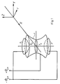
- Fig. 1 the standard structure is shown, which consists of a ring electrode (1) of radius r and two end caps (2) of distance 2z0 .
- r0 and z0 are characteristic dimensions, which are related to the spacings of the hyperbolic surfaces from the center of the structure.
- the application of the three-dimensional rotationally symmetric quadrupole field to trap ions and charged particles and to study the properties of the trapped species and to generate mass spectra is well reported in the literature (Quadrupole Mass Spectrometry- and Its Applications, P.H. Dawson, Ed., Elsevier, Amsterdam, 1976, and D. Price and J.F.J. Todd, Int. Mass Spectrom. Ion Processes, 60 (1984) 3).
- This object is achieved according to the invention by continuously varying the resultant electric potential ⁇ qo across the electrode structure.
- those surfaces of the electrode structure forming the boundary of the electric field do not have to be parallel to the equipotential surfaces of the electric field at its boundary.
- those parts of the electrode structure forming the boundary of the electric field do not necessarily have to be curved, but are only required to form contours corresponding to the boundary conditions of an implied resultant electric potential generating the quadrupole electric field or an electric field of higher multipole moments.
- the resultant electric potential is continuously varied with position on the surface of the electrode structure adjacent to the electric field.
- the resultant electric potential is composed of a plurality of single electric potentials being applied each to separate electrodes forming the electrode structure. In both cases as a result there will be an electric potential continuously varied across the electrode structure and generating a quadrupole field.
- a second electric field inside the electrode structure which is homogeneous in symmetry axis direction can be generated and superimposed to the quadrupole field without interaction.
- the possibility of creating such a homogeneous electric field not interfering with the quadrupole electric field is one of the major advantages of the method according to the invention.
- the main application of this method will be the field of mass-spectrometry, especially the mass selected analysis of stored ions.
- the ions to be analyzed are generated outside the electrode structure. They could be e.g. components of an ion beam directed into the electrode structure.
- Another possibility is the creation of ions out of neutral particles inside the boundary of the quadrupole field.
- the ionization may be performed by electron impact, ion-impact or resonant photon absorption. Accordingly for the generation of the ions an electron beam, a primary ion beam or a laser beam can be employed. It can be of advantage, if the ionizing beams are pulsed.
- the above mentioned second, homogeneous electric field inside the boundary of the quadrupole electric field or the electric field of higher multipole moments is used for a mass-to-charge specific excitation of the fundamental frequencies of the ions to be analyzed.
- This will cause a resonant movement of the excited charged particles in the direction of the symmetry axis.
- image current signals are induced in the electrode structure which can be differentially detected and processed into a frequency-analyzer.
- Employing Fourier Transformation techniques for the frequency analysis can be especially advantageous.
- the excitation of the ions under investigation by the second homogeneous field is used for ejecting the ions out of the boundaries of the first electric field and detecting them with a charge-sensitive detector.
- a charge-sensitive detector This can be, for example, desirable, if the number of ions under investigation inside the electrode structure is so small, that the image current induced by the ion movements has an amplitude below the noise signal level.
- an adapt detector like e.g. a secondary electron multiplier, a channeltron or multi-channel-plates, might be the only alternative to the image current method.
- an electrode structure is operated according to the methods described above.
- This electrode structure defines on the one hand the boundary of the electric quadrupole field or the electric field of higher multi-pole moments, on the other hand the behaviour of the electric potential being applied to the electrode structure and generating the electric field.
- those parts of the electrode structure facing the electric field and defining the boundary of the field consist of electrically resistive material. This can be accomplished either by coating a non-conductive substrate material with resistive material at those parts adjacent to the electric field, or one can use resistance wires for the construction of the electrode structure.
- the operation of the electrode structure is similar to that of a continuous potentiometer and the construction consists substantially of a single part.
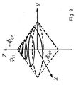
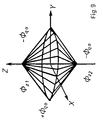
- the resistance wire can be helically wound or constructed to form a double umbrella frame-work.
- the electrode structure is built of metallic material.
- the electrode structure is constructed of a plurality of metallic sheets to which a plurality of single electric potentials is applied constituting a resultant electric potential which in turn generates the quadrupole electric field or an electric field of higher multipole moments.
- the spatial boundary of the rotationally symmetric quadrupole field can be defined by circular holes with successively varying radii whereby the metallic sheets are disposed with faces parallel in equal or unequal distances.
- the metallic sheets are linked together by a resistance network.
- a resistance network it is not necessary to generate an adapt potential for each sheet but the negative and the positive output of a single voltage source is applied to the ends of the electrode structure and the resistances of the network are chosen such that the potentials and the single sheets form a resultant continuously varying potential.
- the metallic sheets are equally spaced and the resistors are of the same resistance. This facilitates the manufacturing of the electrode structure.
- the metallic sheets with equal areas are equally spaced. Applying RF-voltage to this electrode structure one can even omit the resistance network.
- the electrode structures according to the invention comprise apertures.
- the apertures are already built in by the construction principle.
- two ring plane electrodes distant ⁇ 1 z o from the plane defined by the annular contact line of the two cones are provided for detecting the image currents of ions moving in symmetry axis direction inside the field boundary.
- the invention provides a method and the corresponding structures of generating an exact three-dimensional quadrupole field or an electric field of higher multipole moments and a method and corresponding structures for superimposing further homogeneous electric fields in symmetry-axis direction on the first field.
- the application of the device to store charged particles and to generate mass spectra by simultaneous or consecutive detection of the image currents induced by the charged particles in the electrode structure or by charge detection is also presented.
- the trajectories of the charged particles in the fields can be expressed by the canonical form of the linear Mathieu equation with parameters
- the characteristic parameters ⁇ r,z satisfy 0 ⁇ ⁇ 1 and have a known relationship with parameters a r,z and q r,z . Therefore a relationship between the ⁇ values and the m/q ratios can be obtained
- the component frequencies of ion motion are unique and specific for particular m/q ratios. According to the selected range of stable ions, in practical operation a r and a z can be set to zero.
- the force F ( ⁇ ) depends only on time and not on position of the charged particles.
- eq. (6) consists of one independent part with initial conditions and of a second part given in eq. (2).
- the excitation frequency matches the characteristic frequency of a charged particle with certain m/q or a subharmonic thereof, resonance occurs and the trapped particle moves with a frequency equal to the characteristic frequency.
- the amplitude of motion will grow linearly with time.
- the motion of the trapped particles is now coherent in z direction. If the characteristic frequencies of charged particles differ from the excitation frequency no resonance occurs.
- the said quadrupole fields have two functions: to trap charged particles with a certain range of m/q ratios and to cause oscillations with frequencies characteristic for the different m/q ratios of the charged particles. With the aid of excitation fields the characteristic frequencies of the trapped charged particles can be excited, so that the motion is coherent in the z direction. Usually the above mentioned frequencies are in the RF-range.
- boundary conditions e.g. the contours of a curved surface and the corresponding potential values on the surface
- unique electrostatic fields can be defined within the interior region of the boundaries.
- a definite electrostatic field has been defined according to eq. (7) a wide variety of corresponding boundary conditions according to (8) is still possible. If the potential values on each point of a curved surface correspond to the values of the definite electrostatic field at this point, the Laplace equation (7) and the boundary conditions (8) are also satisfied. If we apply this idea to three-dimensional quadrupole fields, we can select the ideal boundary conditions and the ideal electrode configurations for practical applications.
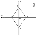
- the potential values vary linearly along the plane curves.
- ⁇ z1 and ⁇ z2 are the applied potentials to generate an additional electric field.
- the realization of the exact three-dimensional quadrupole field or an electric field of higher multipole moments according to the new method depends on the way of generation of continuously varied potentials on the corresponding boundaries.
- Such a continuously varied potential can be realized by a potentiometer-type structure employing electrodes made of electrically restistive material, with the voltage needed for generation of the required surface potential applied on the two ends of the electrode structure situated on the z-axis. Typical values of resistance between the two ends of the electrode are ranging from 1 to 100 k ⁇ .
- the electrode structure consists of a nonconductive substrate material, e.g. ceramics. with an electrically resistive coating.
- the electrode structure consists of a polymeric halogenized polyolefin, especially of polytetraflouorine-ethylene (PTFE) like Teflon, having a high share of carbon ranging especially between 10 and 30% wt.
- PTFE polytetraflouorine-ethylene
- the resistive material in the electrode structure comprises semiconductor material like Si, Ge or GaAs.
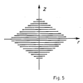
- a plurality of metallic sheets is employed as electrode structure, the sheets having circular holes with successively varying radii to form the inner surface of the rotationally symmetric field boundary and being densely placed parallel to each other and in equal or unequal distances.
- These sheets are linked together by a resistance network dimensioned such that applying a voltage according to eq. (1) to the ends of the network results in a potential according to eq. (9).
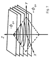
- all resistors have equal resistance and the network can even be omitted if the areas of each metallic sheet are equal and radio frequency is supplied (cf. fig. 7).
- the electrode structures according to the invention comprise apertures disposed at opposite points on the boundary surface with respect to the symmetry center of the cell.
- the particles to be studied inside the electric field and/or means for ionizing these particles can pass through those apertures.
- An embodiment of the electrode structure comprises sample beam inlets in the symmetry axis of the electrode structure coaxial with the ionizing electron beam or laser beam discussed later.
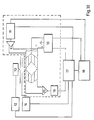
- the three-dimensional quadrupole or higher multipole RF field is generated by the potential of the RF supply 10 connected to an electrode structure as shown in fig. 7.
- the additional homogeneous electric field is generated by the excitation waveform generator 11.
- Ions are generated by a pulsed electron beam.
- the filament supply 12 operates the filament 13, the gate voltage supply pulses 14 the electron beam.
- any other ionization techniques can be applied. It is, for example, possible to use an ion beam for secondary ionization of particles inside the cell, especially if one wants to study scattering and charge transfer processes.
- photoionization can be employed, preferably using a laser beam which can be c.w. or pulsed. Because of the high frequency-selectiveness of photoinization processes the masses of the particles under investigation inside the quadrupole field can be preselected by the choice of the proper excitation frequency leading to photoionization which can in turn be performed using a tuneable laser.
- the ions to be studied inside the cell can be injected into the cell already in form of a pulsed or continuous ion beam.
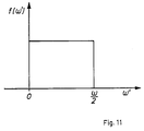
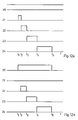
- a pulse of excitation frequencies including all the characteristic frequencies of the ions under investigation is applied, well distributed as shown in fig. 11.
- the resonant ions absorb power and a coherent motion in z axis direction is generated.
- the structure under consideration is equivalent to a capacitor consisting of a pair of parallel plates.
- the image current signal induced by the coherent motion of the ions in z axis direction can be detected on the boundary of the structure as if it were a capacitor with parallel plates.
- the image current signal is amplified with a high gain broad band amplifier 15.
- the resulting transient signal can be subjected to digital data processing after digitation with an analog-to-digital converter 16.
- the frequency spectrum of the characteristic frequencies of the stored ions can be obtained by any frequency analysis technique. Fourier transformation is especially well suited.
- the frequency analysis and the control is performed by a scan and acquisition computer 17. The timing sequences are referenced to the master clock 18.
- the stored ions after mass-to-charge selective ejection by excitation of the fundamental frequencies with the homogeneous electric field can be detected by a charge-sensitive detector like Secondary Electron Multiplier or channel plate.
- a charge-sensitive detector like Secondary Electron Multiplier or channel plate.
- the spectrometer is operated in a pulsed mode, as shown in fig. 12.
- the RF trapping voltage 20 is applied constantly during the experiment. First, all ions being possibly in the trap are quenched by a pulse 21 starting at a time t1. At t2 ions are generated with a pulse 22, e.g. an electron beam pulse of electrons having kinetic energy sufficient for ion formation. At t3 ions are excited with pulse 23 and detected with detection pulse 24 starting at t4. At the time t5 a measuring cycle is completed.
- the quenching pulse 21 is not activated. Instead, the RF trapping voltage 20 is not constantly applied, but is started at time t1 and disconnected at time t5. Ions being in the cell after the time t5 will, due to their finite kinetic energy, drift to the electrode structure and become neutralized or even pass the field boundary, if they, by chance, find the above mentioned apertures in the electrode structure. At the beginning of the next measuring cycle, with a great probability, there will be no more charged particles inside the field boundary.
- the spectral resolution depends on the observation time of the transient signal generated by the coherently moving ions.
- the trapping quadrupole or higher multipole field and the z axis excitation fields are both exact and without mutual interference, the trajectories of the ions are exactly described by the even linear Mathieu equation.
- the excitation of the ions is independent of their position in the trap.
- the image current is proportional to the number of ions in the trap.
- the m/q ratios of the ions correspond to their characteristic frequencies.
Landscapes
- Chemical & Material Sciences (AREA)
- Analytical Chemistry (AREA)
- Electron Tubes For Measurement (AREA)
Claims (14)
- Verfahren zum Erzeugen eines dreidimensionalen rotationssymmetrischen elektrischen Quadrupolfeldes oder eines elektrischen Feldes von höheren Multipolmomenten innerhalb einer Elektrodenstruktur, die die Grenze des Feldes durch Anlegen eines resultierenden elektrischen Potentials Φqo an die Elektrodenstruktur bildet, dadurch gekennzeichnet, daß das resultierende elektrische Potential Φqo kontinuierlich über die Elektrodenstruktur variiert wird.
- Verfahren nach Anspruch 1, dadurch gekennzeichnet, daß das resultierende elektrische Potential kontinuierlich mit der Position an der Oberfläche der Elektrodenstruktur angrenzend an das Quadrupolfeld oder höhere Multipolfeld variiert wird.
- Verfahren nach Anspruch 1, dadurch gekennzeichnet, daß eine Mehrzahl von einzelnen elektrischen Potentialen, die jeweils an separate Elektroden angelegt werden, die die Elektrodenstruktur bilden, das resultierende elektrische Potential bildet, das kontinuierlich über die Elektrodenstruktur variiert wird.
- Verfahren nach Anspruch 2 oder 3, dadurch gekennzeichnet, daß das resultierende elektrische Potential linear entlang der Kurve einer beliebigen zentralen Querschnittsebene der Elektrodenstruktur variiert wird.
- Verfahren nach einem der vorhergehenden Ansprüche, gekennzeichnet durch Anlegen eines zweiten resultierenden elektrischen Potentials an die Elektrodenstruktur zur Erzeugung eines zweiten homogenen elektrischen Feldes in Richtung der Symmetrie-Achse, das dem dreidimensionalen rotationssymmetrischen elektrischen Quadrupolfeld oder dem elektrischen Feld von höheren Multipolmomenten ohne gegenseitige Beeinflussung überlagert ist.
- Verfahren nach einem der vorhergehenden Ansprüche, gekennzeichnet durch die Anwendung des Verfahrens zur massenspektrometrischen Analyse von gespeicherten Ionen.
- Verfahren nach Anspruch 5 und 6, dadurch gekennzeichnet, daß die zu analysierenden Ionen massenselektiv innerhalb der Grenze des elektrischen Quadrupol- oder höheren Multipolfeldes gespeichert werden, und daß die Masse-zu-Ladungspezifischen fundamentalen Frequenzen der zu analysierenden Ionen durch das zweite homogene elektrische Feld angeregt werden.
- Verfahren nach Anspruch 7, dadurch gekennzeichnet, daß die Bildstromsignale in der Elektrodenstruktur, die aus den Bewegungen der Ionen aufgrund von Resonanzanregung durch das zweite elektrische Feld resultieren, differentiell detektiert werden.
- Verfahren nach Anspruch 8, dadurch gekennzeichnet, daß ein Massenspektrum der Ionen durch Anwendung einer Frequenzanalyse auf die Bildstromsignale erzeugt wird.
- Verfahren nach Anspruch 7, dadurch gekennzeichnet, daß die Ionen aus den Grenzen des Quadrupolfeldes hinausgeworfen und mit einem ladungssensitiven Detektor detektiert werden.
- Verwendung einer Elektrodenstruktur in einem Verfahren nach einem der vorhergehenden Ansprüche, dadurch gekennzeichnet, daß diejenigen Teile der Elektrodenstruktur, die dem elektrischen Quadrupol- oder höheren Multipolfeld gegenüberliegen und somit dessen Grenzen definieren, aus elektrisch resistivem Material bestehen.
- Verwendung einer Elektrodenstruktur nach Anspruch 11, dadurch gekennzeichnet, daß die Elektrodenstruktur ein nicht leitendes Substratmaterial aufweist, das an den dem Quadrupol- oder höheren Multipolfeld gegenüberliegenden Teilen mit resistivem Material überzogen ist.
- Verwendung einer Elektrodenstruktur nach Anspruch 11, dadurch gekennzeichnet, daß die Elektrodenstruktur aus einem oder mehr Widerstandsdrähten besteht, die die Grenze des Quadrupol- oder höheren Multipolfeldes definieren.
- Verwendung einer Elektrodenstruktur bei einem Verfahren nach einem der Ansprüche 1 bis 6, dadurch gekennzeichnet, daß die Elektrodenstruktur aus einer Mehrzahl von metallischen Platten besteht, die jeweils ein kreisförmiges Loch aufweisen, das die Grenze des Quadrupol- oder höheren Multipolfeldes definiert, wobei der Radius des Loches sukzessiv von Platte zu Platte variiert, und wobei die Platten dicht aneinander und die Flächen parallel in gleichmäßigen oder ungleichmäßigen Abständen angeordnet sind.
Applications Claiming Priority (1)
| Application Number | Priority Date | Filing Date | Title |
|---|---|---|---|
| PCT/EP1990/000030 WO1991011016A1 (en) | 1990-01-08 | 1990-01-08 | Generation of an exact three-dimensional quadrupole electric field |
Publications (2)
| Publication Number | Publication Date |
|---|---|
| EP0509986A1 EP0509986A1 (de) | 1992-10-28 |
| EP0509986B1 true EP0509986B1 (de) | 1995-05-31 |
Family
ID=8165455
Family Applications (1)
| Application Number | Title | Priority Date | Filing Date |
|---|---|---|---|
| EP90903006A Expired - Lifetime EP0509986B1 (de) | 1990-01-08 | 1990-01-08 | Erzeugung eines genauen dreidimensionalen elektrischen quadrupolfeldes |
Country Status (4)
| Country | Link |
|---|---|
| EP (1) | EP0509986B1 (de) |
| CA (1) | CA2033753C (de) |
| DE (1) | DE69019829T2 (de) |
| WO (1) | WO1991011016A1 (de) |
Families Citing this family (4)
| Publication number | Priority date | Publication date | Assignee | Title |
|---|---|---|---|---|
| US5206506A (en) * | 1991-02-12 | 1993-04-27 | Kirchner Nicholas J | Ion processing: control and analysis |
| GB0816258D0 (en) * | 2008-09-05 | 2008-10-15 | Ulive Entpr Ltd | Process |
| DE102011118052A1 (de) | 2011-11-08 | 2013-07-18 | Bruker Daltonik Gmbh | Züchtung von Obertönen in Schwingungs- Massenspektrometern |
| CN115856453B (zh) * | 2022-12-05 | 2025-06-06 | 广东电网有限责任公司 | 一种架空输电线路导线表面电场强度计算方法 |
Family Cites Families (4)
| Publication number | Priority date | Publication date | Assignee | Title |
|---|---|---|---|---|
| IT528250A (de) * | 1953-12-24 | |||
| US3527939A (en) * | 1968-08-29 | 1970-09-08 | Gen Electric | Three-dimensional quadrupole mass spectrometer and gauge |
| US3648046A (en) * | 1970-05-18 | 1972-03-07 | Granville Phillips Co | Quadrupole gas analyzer comprising four flat plate electrodes |
| SU1104602A1 (ru) * | 1982-02-19 | 1984-07-23 | Рязанский Радиотехнический Институт | Способ анализа ионов в гиперболоидном масс-спектрометре типа трехмерной ловушки |
-
1990
- 1990-01-08 WO PCT/EP1990/000030 patent/WO1991011016A1/en not_active Ceased
- 1990-01-08 EP EP90903006A patent/EP0509986B1/de not_active Expired - Lifetime
- 1990-01-08 DE DE69019829T patent/DE69019829T2/de not_active Expired - Lifetime
-
1991
- 1991-01-08 CA CA002033753A patent/CA2033753C/en not_active Expired - Lifetime
Also Published As
| Publication number | Publication date |
|---|---|
| WO1991011016A1 (en) | 1991-07-25 |
| DE69019829D1 (de) | 1995-07-06 |
| DE69019829T2 (de) | 1996-03-14 |
| CA2033753A1 (en) | 1991-07-09 |
| CA2033753C (en) | 1995-11-21 |
| EP0509986A1 (de) | 1992-10-28 |
Similar Documents
| Publication | Publication Date | Title |
|---|---|---|
| US5283436A (en) | Generation of an exact three-dimensional quadrupole electric field and superposition of a homogeneous electric field in trapping-exciting mass spectrometer (TEMS) | |
| US5019706A (en) | Ion cyclotron resonance spectrometer | |
| CA1207918A (en) | Method of mass analyzing a sample by use of a quadrupole ion trap | |
| US6157031A (en) | Quadropole mass analyzer with linear ion trap | |
| US6727495B2 (en) | Ion mobility spectrometer with high ion transmission efficiency | |
| US7928375B1 (en) | Microfabricated linear Paul-Straubel ion trap | |
| EP0817239B1 (de) | Ionenspeicherungsvorrichtung für Massenspektrometrie | |
| US5783824A (en) | Ion trapping mass spectrometry apparatus | |
| US7755040B2 (en) | Mass spectrometer and electric field source for mass spectrometer | |
| EP0871201B1 (de) | Massenspektrometer | |
| US6838666B2 (en) | Rectilinear ion trap and mass analyzer system and method | |
| US8704172B2 (en) | Excitation of ions in an ICR-cell with structured trapping electrodes | |
| EP1779408B1 (de) | Massenspektrometer | |
| US6762406B2 (en) | Ion trap array mass spectrometer | |
| US6870158B1 (en) | Microfabricated cylindrical ion trap | |
| US7868289B2 (en) | Mass spectrometer ion guide providing axial field, and method | |
| US7154088B1 (en) | Microfabricated ion trap array | |
| WO1997014174A1 (en) | Miniature quadrupole mass spectrometer array | |
| US8704173B2 (en) | Ion cyclotron resonance measuring cells with harmonic trapping potential | |
| US8334506B2 (en) | End cap voltage control of ion traps | |
| US8129678B2 (en) | Method and apparatuses for ion cyclotron spectrometry | |
| EP0509986B1 (de) | Erzeugung eines genauen dreidimensionalen elektrischen quadrupolfeldes | |
| EP0456516B1 (de) | Ionenbündelvorrichtung | |
| Jackson et al. | Matrix-shimmed ion cyclotron resonance ion trap simultaneously optimized for excitation, detection, quadrupolar axialization, and trapping | |
| Oksman | A Fourier transform time-of-flight mass spectrometer. A SIMION calculation approach |
Legal Events
| Date | Code | Title | Description |
|---|---|---|---|
| PUAI | Public reference made under article 153(3) epc to a published international application that has entered the european phase |
Free format text: ORIGINAL CODE: 0009012 |
|
| 17P | Request for examination filed |
Effective date: 19920701 |
|
| AK | Designated contracting states |
Kind code of ref document: A1 Designated state(s): DE GB |
|
| 17Q | First examination report despatched |
Effective date: 19940721 |
|
| GRAA | (expected) grant |
Free format text: ORIGINAL CODE: 0009210 |
|
| AK | Designated contracting states |
Kind code of ref document: B1 Designated state(s): DE GB |
|
| REF | Corresponds to: |
Ref document number: 69019829 Country of ref document: DE Date of ref document: 19950706 |
|
| PLBE | No opposition filed within time limit |
Free format text: ORIGINAL CODE: 0009261 |
|
| STAA | Information on the status of an ep patent application or granted ep patent |
Free format text: STATUS: NO OPPOSITION FILED WITHIN TIME LIMIT |
|
| 26N | No opposition filed | ||
| REG | Reference to a national code |
Ref country code: GB Ref legal event code: IF02 |
|
| PGFP | Annual fee paid to national office [announced via postgrant information from national office to epo] |
Ref country code: DE Payment date: 20090122 Year of fee payment: 20 |
|
| PGFP | Annual fee paid to national office [announced via postgrant information from national office to epo] |
Ref country code: GB Payment date: 20090126 Year of fee payment: 20 |
|
| REG | Reference to a national code |
Ref country code: GB Ref legal event code: PE20 Expiry date: 20100107 |
|
| PG25 | Lapsed in a contracting state [announced via postgrant information from national office to epo] |
Ref country code: GB Free format text: LAPSE BECAUSE OF EXPIRATION OF PROTECTION Effective date: 20100107 |
|
| PG25 | Lapsed in a contracting state [announced via postgrant information from national office to epo] |
Ref country code: DE Free format text: LAPSE BECAUSE OF EXPIRATION OF PROTECTION Effective date: 20100108 |