EP0509380A2 - Improvement in or relating to a press-contact type electric connector for a flat, flexible cable - Google Patents
Improvement in or relating to a press-contact type electric connector for a flat, flexible cable Download PDFInfo
- Publication number
- EP0509380A2 EP0509380A2 EP92106040A EP92106040A EP0509380A2 EP 0509380 A2 EP0509380 A2 EP 0509380A2 EP 92106040 A EP92106040 A EP 92106040A EP 92106040 A EP92106040 A EP 92106040A EP 0509380 A2 EP0509380 A2 EP 0509380A2
- Authority
- EP
- European Patent Office
- Prior art keywords
- flat
- housing
- flexible cable
- cable
- printed circuit
- Prior art date
- Legal status (The legal status is an assumption and is not a legal conclusion. Google has not performed a legal analysis and makes no representation as to the accuracy of the status listed.)
- Withdrawn
Links
Images


Classifications
-
- H—ELECTRICITY
- H01—ELECTRIC ELEMENTS
- H01R—ELECTRICALLY-CONDUCTIVE CONNECTIONS; STRUCTURAL ASSOCIATIONS OF A PLURALITY OF MUTUALLY-INSULATED ELECTRICAL CONNECTING ELEMENTS; COUPLING DEVICES; CURRENT COLLECTORS
- H01R12/00—Structural associations of a plurality of mutually-insulated electrical connecting elements, specially adapted for printed circuits, e.g. printed circuit boards [PCB], flat or ribbon cables, or like generally planar structures, e.g. terminal strips, terminal blocks; Coupling devices specially adapted for printed circuits, flat or ribbon cables, or like generally planar structures; Terminals specially adapted for contact with, or insertion into, printed circuits, flat or ribbon cables, or like generally planar structures
- H01R12/70—Coupling devices
- H01R12/77—Coupling devices for flexible printed circuits, flat or ribbon cables or like structures
- H01R12/78—Coupling devices for flexible printed circuits, flat or ribbon cables or like structures connecting to other flexible printed circuits, flat or ribbon cables or like structures
-
- H—ELECTRICITY
- H01—ELECTRIC ELEMENTS
- H01R—ELECTRICALLY-CONDUCTIVE CONNECTIONS; STRUCTURAL ASSOCIATIONS OF A PLURALITY OF MUTUALLY-INSULATED ELECTRICAL CONNECTING ELEMENTS; COUPLING DEVICES; CURRENT COLLECTORS
- H01R12/00—Structural associations of a plurality of mutually-insulated electrical connecting elements, specially adapted for printed circuits, e.g. printed circuit boards [PCB], flat or ribbon cables, or like generally planar structures, e.g. terminal strips, terminal blocks; Coupling devices specially adapted for printed circuits, flat or ribbon cables, or like generally planar structures; Terminals specially adapted for contact with, or insertion into, printed circuits, flat or ribbon cables, or like generally planar structures
- H01R12/50—Fixed connections
- H01R12/59—Fixed connections for flexible printed circuits, flat or ribbon cables or like structures
- H01R12/62—Fixed connections for flexible printed circuits, flat or ribbon cables or like structures connecting to rigid printed circuits or like structures
-
- H—ELECTRICITY
- H01—ELECTRIC ELEMENTS
- H01R—ELECTRICALLY-CONDUCTIVE CONNECTIONS; STRUCTURAL ASSOCIATIONS OF A PLURALITY OF MUTUALLY-INSULATED ELECTRICAL CONNECTING ELEMENTS; COUPLING DEVICES; CURRENT COLLECTORS
- H01R12/00—Structural associations of a plurality of mutually-insulated electrical connecting elements, specially adapted for printed circuits, e.g. printed circuit boards [PCB], flat or ribbon cables, or like generally planar structures, e.g. terminal strips, terminal blocks; Coupling devices specially adapted for printed circuits, flat or ribbon cables, or like generally planar structures; Terminals specially adapted for contact with, or insertion into, printed circuits, flat or ribbon cables, or like generally planar structures
- H01R12/70—Coupling devices
- H01R12/7082—Coupling device supported only by cooperation with PCB
Definitions
- the present invention relates to an electric connector, and more particularly to an improvement of an electric connector for permitting a solderless connection between the conductors of a flat, flexible cable and a circuit pattern on a printed circuit board by pressing the conductors of the flat, flexible cable against the circuit pattern.
- a conventional electric connector is composed of male and female parts, which are soldered to the exposed conductors of the stripped end of a flat, flexible cable and to selected conductors of a printed circuit pattern respectively.
- a desired electric connection can be made by coupling the male and female parts of the electric connector. Soldering, however, is a tedious and time-consuming work. In an attempt to eliminate such tedious and time-consuming work, a solderless connection in the form of press contact was proposed.
- This type of solderless connector comprises a housing having a resilient contact piece integrally connected therewith, permitting insertion of a flat, flexible cable to place the conductor surface of the flat, flexible cable in registration with selected part of the circuit pattern on a printed circuit board.
- the resilient contact piece is adapted to push the conductor surface of the flat, flexible cable against the selected parts of the circuit pattern.
- solderless connectors in the prior art have some disadvantages.
- the connector housings of the prior art can be fixed to a printed circuit board by fitting the pins or pegs of the connector housings in corresponding holes of the printed circuit board, but these connector housings have no means to positively hold the flat cable therein.
- the flat cable is held only by a resilient contact piece, which pushes the end of the flat cable against the printed board. If undesired external force should be applied to the flat cable, it is liable to cause the flat cable to change in position. Thus, incomplete electric connection may result, leading to malfunction of the associated electric apparatus.
- one object of the present invention is to provide a solderless connector which permits the exact positioning of a flat, flexible cable in the connector housing, particularly in the area in which a required electric connection is to made between the cable and the printed circuit pattern.
- Another object of the present invention is to provide a solderless connector which is capable of positively holding a flat, flexible cable in the connector housing, thus preventing movement of the flat cable, which otherwise, would be caused by external force.
- an electric connector for connecting a flat, flexible cable to a printed circuit board comprising a housing having front and rear portions and a slot in the housing front portion permitting insertion of a flat, flexible cable.
- a resilient contact piece integrally connected to the housing is adapted to push the conductor surface of the flat, flexible cable against and in registration with selected parts of the circuit pattern on a printed circuit board.
- the housing has a groove formed in its rear portion to accommodate the leading edge of said flat, flexible cable when inserted in said housing.
- the housing also has a flexible lock piece integrally connected to the housing in the vicinity of the cable slot to push the rear side of the flat, flexible cable against the housing preventing the removal of the cable from the housing.
- the free end of said resilient contact piece may have notches formed thereon.
- FIGURE 1 is a perspective top view of a solderless connector according to a first embodiment of the present invention.
- FIGURE 2 is a perspective bottom view of the solderless connector of Fig. 1.
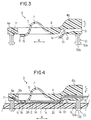
- FIGURE 3 is a section of the solderless connector taken along the line 3-3 in Fig. 2.
- FIGURE 4 is a similar section, but showing how a flat, flexible cable is connected when the solderless connector is applied to a printed circuit board.
- FIGURE 5 is an enlarged perspective view of the free end of the resilient contact piece of the solderless connector.
- FIGURE 6 is an enlarged section, showing the lock piece of the solderless connector.
- FIGURE 7 is an enlarged perspective view of the free end of the resilient contact piece of a solderless connector according to a second embodiment of the present invention.
- FIGURE 8 is an enlarged section, showing the lock piece of a solderless connector according to a third embodiment of the present invention.
- Figs. 1 to 6 show a solderless connector 3 according to a first embodiment of the present invention. It permits a solderless connection between the conductors 2A of a flat, flexible cable 2 and the circuit pattern 1A of a printed circuit board 1 in the form of press contact.
- a plurality of resilient contact pieces 5 are arranged parallel in lateral directions B, and are integrally connected to the lateral side of a housing 4 in the form of cantilevered arms, extending parallel in the longitudinal direction A. These resilient contact pieces 5 are wavy in shape. The free end of each resilient contact piece 5 constitutes a press contact section 6, which extends from a rising section 7.
- the housing 4 has a cable slot 8 passing through its rear portion, permitting insertion of a flat, flexible cable 2 into housing 4.
- split pins 10 are fixed to the four corners of the housing 4 for attaching the housing 4 to a printed circuit board 1, which has holes 9 to catch the pins 10 when inserted therein.
- Each split pin 10 has four enlarged lock quarters 10a separated by slots 10b, thereby providing resiliency.
- the split pin head When the split pin head is inserted in a corresponding hole 9, its diameter reduces yieldingly, thereby allowing the split pin head to pass through the hole 9 and resiliently return to its original, stress-free condition, so that the four enlarged lock quarters 10a may be caught by the rear side 1a of the printed circuit board 1 around the hole 9.
- the connector housing 4 is attached to the printed circuit board 1.
- Housing 4 has a groove 11 made on its front portion 4a, thereby accommodating the leading edge of a flat, flexible cable 2 when inserted in the housing 4. Specifically, after the cable 2 is inserted from the cable slot 8 into the connector housing 4, the cable 2 extends longitudinally on the bottom side of the connector housing 4. The end 2b of the cable 2 is pushed in the groove 11 of the front portion 4a of the conductor housing 4, and then the cable 2 is automatically put in correct position in the conductor housing 4.
- Housing 4 has a lock piece 12 integrally connected in the vicinity of the cable slot 8 of the housing 4 in the form of a short cantilevered arm. Specifically, one end of the lock piece 12 is integrally connected to the housing 4 whereas the free end of the lock piece 12 constitutes a locking arm section 13, which has points 14 formed thereon. A cable insertion gap 15 which is large enough to permit insertion of the cable 2 is defined between the lock piece 12 and the bottom side of the connector housing 4.
- the lock piece 12 When the connector housing 4 having a flat, flexible cable 2 inserted in the cable insertion gap 15, is fixed to a printed circuit board 1, the lock piece 12 is yieldingly bent upwards by the printed circuit board 1 so that the rear side 2C of the cable is pushed towards the ceiling of the connector housing 4.
- the cable 2 cannot be held by the connector housing 4, but when the connector housing 4 is fixed to the printed circuit board 1, the cable 2 is pinched between the ceiling of the connector housing 4 and the upper surface of the lock piece 12.
- the lock piece 15 may have locking points 14 formed thereon.
- One end of the flat, flexible cable 2 is stripped on one side to expose its conductors 2A whereas the other end of the cable 2 is connector to an associated electric apparatus.
- solderless connector 3 The manner in which the solderless connector 3 is used by first inserting one end 2b of a flat, flexible cable 2 into the cable slot 8 of the connector housing 4 to pass through the insertion gap 15 and pass by the free contact end 6 of the resilient contact piece 5.
- the end 2b of the cable 2 is inserted in the groove 11 of the front portion 4a of the connector housing 4.
- the connector housing 4 having the cable 2 inserted therein is fixed to a printed circuit board 1 by inserting its split pins 10 into corresponding holes 9 of the printed circuit board 1.
- the connector housing 4 is positively fixed to the printed circuit board 1, and at the same time, the exposed conductors 2A of the cable 2 are pushed against the printed circuit pattern 1A of the printed circuit board 1 by the resilient contact piece 5 to make electrical contact therebetween.
- the lock piece 12 positively catches the cable 2 in position, preventing it from moving from the correct position.
- solderless connector according to the second embodiment of the present invention is shown. Specifically, the feature of this particular embodiment resides in the press contact portion 6 of the resilient contact piece 5. It has a plurality of parallel slits.
- a solderless connector according to the third embodiment of the present invention is shown.
- the feature of this particular embodiment resides in the press contact portion 6 of the resilient contact piece 5. It has a plurality of feet 17 to push a plurality of flat, flexible cables 2 laid on each other against a printed circuit board 1.
- a flat, flexible cable can be put in correct position in the connector housing with the aid of the groove in the front portion of the connector housing, thereby assuring good electrical contact between the cable and the printed circuit pattern in position.
- the cable conductor is press-contacted to the printed circuit pattern by the resilient contact piece, and the cable is positively held in correct position by the lock piece, thus preventing undesired movement of the cable from the correct position which otherwise, would be caused if an external force should be applied to the cable.
Abstract
The object of the present invention is to provide a solderless connector which permits the exact positioning of a flat, flexible cable in its housing. An electric connector (3) comprising a housing (4) having a resilient contact piece (5) integrally connected therewith, permitting insertion of a flat, flexible cable (2) to put the conductor surface (2A) of said flat, flexible cable (2) in registration with selected part of the circuit pattern (1A) on a printed circuit board (1), said resilient contact piece (5) being adapted to push the conductor surface (2A) of said flat, flexible cable (2) against said selected part of the circuit pattern (1A), is characterized in that said housing (4) has a groove (11) made on its front portion, thereby accommodating the leading edge of said flat, flexible cable (2) when inserted in said housing (4), and that said housing (4) has a lock piece (12) integrally connected to the vicinity of a cable slot (8), thereby causing said lock piece (12) to be yieldingly bent, pushing the rear side (2c) of said flat, flexible cable (2) when said housing (4) is fixed to said printed circuit board (1) with the aid of associated pins (10).
Description
- The present invention relates to an electric connector, and more particularly to an improvement of an electric connector for permitting a solderless connection between the conductors of a flat, flexible cable and a circuit pattern on a printed circuit board by pressing the conductors of the flat, flexible cable against the circuit pattern.
- As is well known, flat, flexible cables are connected to printed circuit patterns with the aid of electric connectors. A conventional electric connector is composed of male and female parts, which are soldered to the exposed conductors of the stripped end of a flat, flexible cable and to selected conductors of a printed circuit pattern respectively. A desired electric connection can be made by coupling the male and female parts of the electric connector. Soldering, however, is a tedious and time-consuming work. In an attempt to eliminate such tedious and time-consuming work, a solderless connection in the form of press contact was proposed. This type of solderless connector comprises a housing having a resilient contact piece integrally connected therewith, permitting insertion of a flat, flexible cable to place the conductor surface of the flat, flexible cable in registration with selected part of the circuit pattern on a printed circuit board. The resilient contact piece is adapted to push the conductor surface of the flat, flexible cable against the selected parts of the circuit pattern.
- The solderless connectors in the prior art, however, have some disadvantages. First, none have cable positioning means to assure that the stripped end of a flat, flexible cable is put in correct position in the connector housing. It is relatively difficult to put a flat, flexible cable in correct position in the connector housing, and if it is put in a wrong position, a poor electric connection will result. Second, the connector housings of the prior art can be fixed to a printed circuit board by fitting the pins or pegs of the connector housings in corresponding holes of the printed circuit board, but these connector housings have no means to positively hold the flat cable therein. The flat cable is held only by a resilient contact piece, which pushes the end of the flat cable against the printed board. If undesired external force should be applied to the flat cable, it is liable to cause the flat cable to change in position. Thus, incomplete electric connection may result, leading to malfunction of the associated electric apparatus.
- In view of the above, one object of the present invention is to provide a solderless connector which permits the exact positioning of a flat, flexible cable in the connector housing, particularly in the area in which a required electric connection is to made between the cable and the printed circuit pattern.
- Another object of the present invention is to provide a solderless connector which is capable of positively holding a flat, flexible cable in the connector housing, thus preventing movement of the flat cable, which otherwise, would be caused by external force.
-
- To attain these objects an electric connector for connecting a flat, flexible cable to a printed circuit board is provided comprising a housing having front and rear portions and a slot in the housing front portion permitting insertion of a flat, flexible cable. A resilient contact piece integrally connected to the housing is adapted to push the conductor surface of the flat, flexible cable against and in registration with selected parts of the circuit pattern on a printed circuit board. The housing has a groove formed in its rear portion to accommodate the leading edge of said flat, flexible cable when inserted in said housing. The housing also has a flexible lock piece integrally connected to the housing in the vicinity of the cable slot to push the rear side of the flat, flexible cable against the housing preventing the removal of the cable from the housing. The free end of said resilient contact piece may have notches formed thereon.
- Other objects and advantages of the present invention will be understood from the following description of solderless connectors according to the embodiments of the present invention.
- The invention can be more fully understood from the following detailed description thereof in connection with accompanying drawings described as follows.
- FIGURE 1 is a perspective top view of a solderless connector according to a first embodiment of the present invention.
- FIGURE 2 is a perspective bottom view of the solderless connector of Fig. 1.
- FIGURE 3 is a section of the solderless connector taken along the line 3-3 in Fig. 2.
- FIGURE 4 is a similar section, but showing how a flat, flexible cable is connected when the solderless connector is applied to a printed circuit board.
- FIGURE 5 is an enlarged perspective view of the free end of the resilient contact piece of the solderless connector.
- FIGURE 6 is an enlarged section, showing the lock piece of the solderless connector.
- FIGURE 7 is an enlarged perspective view of the free end of the resilient contact piece of a solderless connector according to a second embodiment of the present invention.
- FIGURE 8 is an enlarged section, showing the lock piece of a solderless connector according to a third embodiment of the present invention.
- Figs. 1 to 6 show a
solderless connector 3 according to a first embodiment of the present invention. It permits a solderless connection between theconductors 2A of a flat,flexible cable 2 and thecircuit pattern 1A of a printedcircuit board 1 in the form of press contact. - As best seen from Figs. 1 and 2, a plurality of
resilient contact pieces 5 are arranged parallel in lateral directions B, and are integrally connected to the lateral side of a housing 4 in the form of cantilevered arms, extending parallel in the longitudinal direction A. Theseresilient contact pieces 5 are wavy in shape. The free end of eachresilient contact piece 5 constitutes apress contact section 6, which extends from a risingsection 7. - The housing 4 has a
cable slot 8 passing through its rear portion, permitting insertion of a flat,flexible cable 2 into housing 4. - As best seen from Fig. 2, split
pins 10 are fixed to the four corners of the housing 4 for attaching the housing 4 to a printedcircuit board 1, which hasholes 9 to catch thepins 10 when inserted therein. - Each
split pin 10 has four enlargedlock quarters 10a separated byslots 10b, thereby providing resiliency. When the split pin head is inserted in acorresponding hole 9, its diameter reduces yieldingly, thereby allowing the split pin head to pass through thehole 9 and resiliently return to its original, stress-free condition, so that the four enlargedlock quarters 10a may be caught by the rear side 1a of the printedcircuit board 1 around thehole 9. Thus, the connector housing 4 is attached to the printedcircuit board 1. - Housing 4 has a
groove 11 made on itsfront portion 4a, thereby accommodating the leading edge of a flat,flexible cable 2 when inserted in the housing 4. Specifically, after thecable 2 is inserted from thecable slot 8 into the connector housing 4, thecable 2 extends longitudinally on the bottom side of the connector housing 4. Theend 2b of thecable 2 is pushed in thegroove 11 of thefront portion 4a of the conductor housing 4, and then thecable 2 is automatically put in correct position in the conductor housing 4. - Housing 4 has a
lock piece 12 integrally connected in the vicinity of thecable slot 8 of the housing 4 in the form of a short cantilevered arm. Specifically, one end of thelock piece 12 is integrally connected to the housing 4 whereas the free end of thelock piece 12 constitutes alocking arm section 13, which haspoints 14 formed thereon. Acable insertion gap 15 which is large enough to permit insertion of thecable 2 is defined between thelock piece 12 and the bottom side of the connector housing 4. - When the connector housing 4 having a flat,
flexible cable 2 inserted in thecable insertion gap 15, is fixed to a printedcircuit board 1, thelock piece 12 is yieldingly bent upwards by the printedcircuit board 1 so that the rear side 2C of the cable is pushed towards the ceiling of the connector housing 4. When the flat,flexible cable 2 is inserted in theinsertion gap 15, thecable 2 cannot be held by the connector housing 4, but when the connector housing 4 is fixed to the printedcircuit board 1, thecable 2 is pinched between the ceiling of the connector housing 4 and the upper surface of thelock piece 12. Thus, thecable 2 can be positively held, preventing it from moving away from a correct position even if undesired external force should be applied thereto. Preferably thelock piece 15 may havelocking points 14 formed thereon. - One end of the flat,
flexible cable 2 is stripped on one side to expose itsconductors 2A whereas the other end of thecable 2 is connector to an associated electric apparatus. - The manner in which the
solderless connector 3 is used by first inserting oneend 2b of a flat,flexible cable 2 into thecable slot 8 of the connector housing 4 to pass through theinsertion gap 15 and pass by thefree contact end 6 of theresilient contact piece 5. Theend 2b of thecable 2 is inserted in thegroove 11 of thefront portion 4a of the connector housing 4. Next, the connector housing 4 having thecable 2 inserted therein is fixed to a printedcircuit board 1 by inserting itssplit pins 10 intocorresponding holes 9 of the printedcircuit board 1. Thus, the connector housing 4 is positively fixed to the printedcircuit board 1, and at the same time, the exposedconductors 2A of thecable 2 are pushed against the printedcircuit pattern 1A of the printedcircuit board 1 by theresilient contact piece 5 to make electrical contact therebetween. Also, at the same time, thelock piece 12 positively catches thecable 2 in position, preventing it from moving from the correct position. - Referring to Fig. 7, a solderless connector according to the second embodiment of the present invention is shown. Specifically, the feature of this particular embodiment resides in the
press contact portion 6 of theresilient contact piece 5. It has a plurality of parallel slits. - Referring to Fig. 8, a solderless connector according to the third embodiment of the present invention is shown. The feature of this particular embodiment resides in the
press contact portion 6 of theresilient contact piece 5. It has a plurality offeet 17 to push a plurality of flat,flexible cables 2 laid on each other against a printedcircuit board 1. - As may be understood from the above, a flat, flexible cable can be put in correct position in the connector housing with the aid of the groove in the front portion of the connector housing, thereby assuring good electrical contact between the cable and the printed circuit pattern in position. When the connector housing is fixed to the printed circuit board, the cable conductor is press-contacted to the printed circuit pattern by the resilient contact piece, and the cable is positively held in correct position by the lock piece, thus preventing undesired movement of the cable from the correct position which otherwise, would be caused if an external force should be applied to the cable.
- Numerous modifications and variation of the present invention are possible in light of the above teachings. It is therefore to be understood that within the scope of the appended claims, the present invention may be practiced otherwise than as specifically described herein above.
Claims (4)
- An electric connector (3) for connecting a flat, flexible cable (2) to a printed circuit board (1) comprising:
a housing (4) having front and rear portions,
a slot (8) in the housing front portion permitting insertion of a flat, flexible cable (2),
a resilient contact piece (5) integrally connected therewith and adapted to push the conductor surface (2A) of said flat, flexible cable (2) against and in registration with selected part of the circuit pattern (1A) on a printed circuit board (1),
characterized in that:
said housing (4) having a groove (11) formed in its rear portion to accommodate the leading edge of said flat, flexible cable (2) when inserted in said housing (4), and having a flexible lock piece (12) integrally connected to the housing in the vicinity of the cable slot (8), whereby said lock piece (12) can push the rear side (2c) of said flat, flexible cable (2) against the housing preventing the removal of the cable from the housing. - An electric connector (3) according to claim 1, wherein said lock piece (12) has locking points (14) formed thereon.
- An electric connector (3) according to claim 1, wherein the free end (6) of said resilient contact piece (5) has notches (16) formed thereon.
- An electric connector (3) according to claim 1, wherein said lock piece (12) is positioned so that when the connector is fixed to the printed circuit board the lock piece first contacts the printed circuit board which forces the lock piece (12) against the rear side (2c) of said flat, flexible cable (2).
Applications Claiming Priority (2)
| Application Number | Priority Date | Filing Date | Title |
|---|---|---|---|
| JP033924U JPH0597063U (en) | 1991-04-15 | 1991-04-15 | Electrical connector |
| JP33924/91 | 1991-04-15 |
Publications (2)
| Publication Number | Publication Date |
|---|---|
| EP0509380A2 true EP0509380A2 (en) | 1992-10-21 |
| EP0509380A3 EP0509380A3 (en) | 1995-03-15 |
Family
ID=12400070
Family Applications (1)
| Application Number | Title | Priority Date | Filing Date |
|---|---|---|---|
| EP92106040A Withdrawn EP0509380A3 (en) | 1991-04-15 | 1992-04-08 | Improvement in or relating to a press-contact type electric connector for a flat, flexible cable |
Country Status (4)
| Country | Link |
|---|---|
| US (1) | US5181854A (en) |
| EP (1) | EP0509380A3 (en) |
| JP (1) | JPH0597063U (en) |
| KR (1) | KR950012466B1 (en) |
Cited By (14)
| Publication number | Priority date | Publication date | Assignee | Title |
|---|---|---|---|---|
| DE19750224A1 (en) * | 1997-11-13 | 1999-06-10 | Daimler Chrysler Ag | Plug for releasable electrical connection between flat strip cable and circuit board |
| DE19832011A1 (en) * | 1998-07-16 | 2000-02-03 | Kostal Leopold Gmbh & Co Kg | Flat ribbon cable e.g. for connection to printed circuit board, has springs in insulating housing fitted to cable termination region used to press contact regions of respective conductor paths against corresponding counter-contacts |
| DE19910572A1 (en) * | 1999-03-10 | 2000-09-14 | Delphi Tech Inc | Fastener |
| FR2805668A1 (en) * | 2000-02-29 | 2001-08-31 | Siemens Automotive Sa | Car processing printed circuit board/flat cable connector having stripped cable/printed circuit board tracks interconnection held with retention loop/switch back and circuit board grip. |
| EP1154524A1 (en) * | 2000-05-10 | 2001-11-14 | Sharp Kabushiki Kaisha | Terminal connecting device for flexible substrate |
| DE10157803A1 (en) * | 2001-11-27 | 2003-06-12 | Taller Automotive Gmbh | Connection arrangement has flexible foil positioning arrangement containing spring arrangement for displacing flexible foil flexibly into desired position in contacting area |
| WO2004040712A1 (en) * | 2002-10-31 | 2004-05-13 | Fci | Connector arrangement between a flexible ribbon cable and a component |
| DE102005056147A1 (en) * | 2005-11-23 | 2007-05-31 | Panta Gmbh | Electrical connector |
| US7238032B2 (en) | 2003-10-29 | 2007-07-03 | Fci | Connector arrangement between a flat flex cable and a component |
| WO2010068322A1 (en) * | 2008-09-30 | 2010-06-17 | Symbol Technologies, Inc. | Sealed, solderless i/o connector |
| DE102012211800A1 (en) * | 2012-07-06 | 2014-01-09 | BSH Bosch und Siemens Hausgeräte GmbH | Electrical contact device and display and / or operating device for a household appliance |
| WO2015112659A1 (en) * | 2014-01-24 | 2015-07-30 | 3M Innovative Properties Company | Connector providing solderless contact |
| US9728865B1 (en) | 2016-04-12 | 2017-08-08 | Symbol Technologies, Llc | Sealed, solderless, replaceable, electrical connector |
| EP4000138A4 (en) * | 2019-07-16 | 2023-08-23 | CelLink Corporation | Terminal-free connectors and circuits comprising terminal-free connectors |
Families Citing this family (19)
| Publication number | Priority date | Publication date | Assignee | Title |
|---|---|---|---|---|
| US5399101A (en) * | 1993-12-16 | 1995-03-21 | International Business Machines Corporation | Electrical connector with preloaded contact |
| GB2285893A (en) * | 1994-01-05 | 1995-07-26 | Whitaker Corp | Connector for interconnecting a flexible circuit to a circuit board |
| US5520551A (en) * | 1994-12-01 | 1996-05-28 | The Whitaker Corporation | Molded latching apparatus for printed circuit mounted components |
| US5777855A (en) * | 1996-06-18 | 1998-07-07 | Eastman Kodak Company | Method and apparatus for connecting flexible circuits to printed circuit boards |
| US6000951A (en) * | 1997-03-18 | 1999-12-14 | Prince Corporation | Electrical ribbon wire connectors |
| US5980307A (en) * | 1997-07-23 | 1999-11-09 | Molex Incorporated | Strain relief system for holding cables to circuit boards |
| US6537082B2 (en) | 1997-10-23 | 2003-03-25 | Cinch Connectors, Inc. | Electrical connector |
| WO1999027579A1 (en) * | 1997-11-26 | 1999-06-03 | Applied Materials, Inc. | Damage-free sculptured coating deposition |
| US5980314A (en) * | 1998-03-13 | 1999-11-09 | Molex Incorporated | Electrical connector with improved board mounting peg |
| JP3684304B2 (en) * | 1998-09-02 | 2005-08-17 | パイオニア株式会社 | Locking hook |
| US6676416B1 (en) * | 2000-05-11 | 2004-01-13 | Zyvex Corporation | Ribbon cable and electrical connector for use with microcomponents |
| TW200509329A (en) * | 2003-08-26 | 2005-03-01 | Yung-Shu Yang | LED package material and process |
| KR100671207B1 (en) * | 2005-08-27 | 2007-01-19 | 삼성전자주식회사 | Apparatus for connecting substrate and electrical apparatus having the same |
| US7494344B2 (en) * | 2005-12-29 | 2009-02-24 | Molex Incorporated | Heating element connector assembly with press-fit terminals |
| JP5213629B2 (en) * | 2008-03-07 | 2013-06-19 | スリーエム イノベイティブ プロパティズ カンパニー | Wire connection structure for substrate, method for manufacturing relay connection body, and method for fixing relay connection body |
| US8519274B2 (en) | 2011-03-08 | 2013-08-27 | International Business Machines Corporation | Pin that inserts into a circuit board hole |
| CN104904070B (en) * | 2012-12-11 | 2018-11-13 | 诺基亚技术有限公司 | The device and method that socket contact for contacting flexible flat connector is provided |
| US9413105B2 (en) * | 2014-09-09 | 2016-08-09 | Hon Hai Precision Industry Co., Ltd. | Carrier for flexible printed circuit |
| WO2018075986A1 (en) * | 2016-10-21 | 2018-04-26 | Paricon Technologies Corporation | Cable-to-board connector |
Citations (3)
| Publication number | Priority date | Publication date | Assignee | Title |
|---|---|---|---|---|
| US4169641A (en) * | 1978-06-22 | 1979-10-02 | Amp Incorporated | Connector clip for flat cable |
| US4634195A (en) * | 1985-06-20 | 1987-01-06 | Amp Incorporated | Electrical interconnection device |
| US4639063A (en) * | 1985-12-20 | 1987-01-27 | Amp Incorporated | Electrical connector for flexible film circuits |
Family Cites Families (4)
| Publication number | Priority date | Publication date | Assignee | Title |
|---|---|---|---|---|
| US4252389A (en) * | 1979-03-27 | 1981-02-24 | Amp Incorporated | Zero insertion force connector having integral unloading means |
| US4252392A (en) * | 1979-09-07 | 1981-02-24 | Amp Incorporated | Zero insertion force connector clip |
| US4358172A (en) * | 1980-04-23 | 1982-11-09 | Thomas & Betts Corporation | Connector for electrical interconnection of circuit board and flat multiconductor cable |
| US4871315A (en) * | 1988-03-30 | 1989-10-03 | Burndy Corporation | Ribbon cable connector |
-
1991
- 1991-04-15 JP JP033924U patent/JPH0597063U/en active Pending
-
1992
- 1992-03-30 US US07/860,846 patent/US5181854A/en not_active Expired - Fee Related
- 1992-04-08 EP EP92106040A patent/EP0509380A3/en not_active Withdrawn
- 1992-04-14 KR KR1019920006185A patent/KR950012466B1/en not_active IP Right Cessation
Patent Citations (3)
| Publication number | Priority date | Publication date | Assignee | Title |
|---|---|---|---|---|
| US4169641A (en) * | 1978-06-22 | 1979-10-02 | Amp Incorporated | Connector clip for flat cable |
| US4634195A (en) * | 1985-06-20 | 1987-01-06 | Amp Incorporated | Electrical interconnection device |
| US4639063A (en) * | 1985-12-20 | 1987-01-27 | Amp Incorporated | Electrical connector for flexible film circuits |
Cited By (22)
| Publication number | Priority date | Publication date | Assignee | Title |
|---|---|---|---|---|
| DE19750224A1 (en) * | 1997-11-13 | 1999-06-10 | Daimler Chrysler Ag | Plug for releasable electrical connection between flat strip cable and circuit board |
| DE19750224B4 (en) * | 1997-11-13 | 2005-10-06 | Daimlerchrysler Ag | Plug for making a detachable electrical connection between a ribbon cable and a printed circuit board |
| DE19832011A1 (en) * | 1998-07-16 | 2000-02-03 | Kostal Leopold Gmbh & Co Kg | Flat ribbon cable e.g. for connection to printed circuit board, has springs in insulating housing fitted to cable termination region used to press contact regions of respective conductor paths against corresponding counter-contacts |
| DE19832011B4 (en) * | 1998-07-16 | 2005-12-22 | Leopold Kostal Gmbh & Co. Kg | Ribbon cable with a provided for releasable connection terminal area |
| US6383004B1 (en) | 1999-03-10 | 2002-05-07 | Delphi Technologies, Inc. | Connection element for connecting electrical leads |
| DE19910572A1 (en) * | 1999-03-10 | 2000-09-14 | Delphi Tech Inc | Fastener |
| FR2805668A1 (en) * | 2000-02-29 | 2001-08-31 | Siemens Automotive Sa | Car processing printed circuit board/flat cable connector having stripped cable/printed circuit board tracks interconnection held with retention loop/switch back and circuit board grip. |
| EP1154524A1 (en) * | 2000-05-10 | 2001-11-14 | Sharp Kabushiki Kaisha | Terminal connecting device for flexible substrate |
| US6514089B2 (en) | 2000-05-10 | 2003-02-04 | Sharp Kabushiki Kaisha | Terminal connecting device for flexible substrate |
| DE10157803A1 (en) * | 2001-11-27 | 2003-06-12 | Taller Automotive Gmbh | Connection arrangement has flexible foil positioning arrangement containing spring arrangement for displacing flexible foil flexibly into desired position in contacting area |
| WO2004040712A1 (en) * | 2002-10-31 | 2004-05-13 | Fci | Connector arrangement between a flexible ribbon cable and a component |
| US7144256B2 (en) | 2002-10-31 | 2006-12-05 | Fci | Connector arrangement between a flexible ribbon cable and a component |
| US7238032B2 (en) | 2003-10-29 | 2007-07-03 | Fci | Connector arrangement between a flat flex cable and a component |
| DE102005056147A1 (en) * | 2005-11-23 | 2007-05-31 | Panta Gmbh | Electrical connector |
| EP1791218A3 (en) * | 2005-11-23 | 2007-10-17 | Panta GmbH | Electrical connector |
| WO2010068322A1 (en) * | 2008-09-30 | 2010-06-17 | Symbol Technologies, Inc. | Sealed, solderless i/o connector |
| US7833025B2 (en) | 2008-09-30 | 2010-11-16 | Symbol Technologies, Inc. | Sealed, solderless I/O connector |
| DE102012211800A1 (en) * | 2012-07-06 | 2014-01-09 | BSH Bosch und Siemens Hausgeräte GmbH | Electrical contact device and display and / or operating device for a household appliance |
| WO2015112659A1 (en) * | 2014-01-24 | 2015-07-30 | 3M Innovative Properties Company | Connector providing solderless contact |
| US9825389B2 (en) | 2014-01-24 | 2017-11-21 | 3M Innovative Properties Company | Connector providing solderless contact |
| US9728865B1 (en) | 2016-04-12 | 2017-08-08 | Symbol Technologies, Llc | Sealed, solderless, replaceable, electrical connector |
| EP4000138A4 (en) * | 2019-07-16 | 2023-08-23 | CelLink Corporation | Terminal-free connectors and circuits comprising terminal-free connectors |
Also Published As
| Publication number | Publication date |
|---|---|
| EP0509380A3 (en) | 1995-03-15 |
| KR950012466B1 (en) | 1995-10-18 |
| US5181854A (en) | 1993-01-26 |
| KR920020779A (en) | 1992-11-21 |
| JPH0597063U (en) | 1993-12-27 |
Similar Documents
| Publication | Publication Date | Title |
|---|---|---|
| US5181854A (en) | Press-contact type electric connector for a flat, flexible cable | |
| EP0189234B1 (en) | Connector with conductor retention means | |
| US5257948A (en) | Printed circuit board mounting device for electrical connectors | |
| JP2582043B2 (en) | Electrical connector assembly | |
| EP0706240A1 (en) | Board to board electrical connectors | |
| EP0682385B1 (en) | Electrical connector | |
| EP0961352B1 (en) | Multi-pin connector for flat cable | |
| US5057027A (en) | Female terminal for an electrical connector | |
| US5415573A (en) | Edge mounted circuit board electrical connector | |
| EP0866528A1 (en) | Electrical connector with tool engagement arm | |
| JPH0411346Y2 (en) | ||
| EP0519317A2 (en) | Board edge connector to contain and keep a flat cable parallel to the printed board | |
| US4708416A (en) | Electrical connecting terminal for a connector | |
| JPH02273473A (en) | Electric connector terminal | |
| EP0780931B1 (en) | Connector for flat cables | |
| EP0632549B1 (en) | Electrical connector assembly | |
| US4645277A (en) | Connector for connecting boards | |
| US20020127904A1 (en) | Relay connector | |
| US6273748B1 (en) | Electrical connector assembly | |
| EP0724782B1 (en) | Gang modular jack | |
| GB2278510A (en) | Connector for flat cables | |
| CN216903566U (en) | Pressing assembly and connector thereof | |
| EP0259964A1 (en) | An electrical connector for flexible flat cable | |
| JP3100655B2 (en) | F-type connector seat without screw | |
| JP2581080Y2 (en) | Edge connector |
Legal Events
| Date | Code | Title | Description |
|---|---|---|---|
| PUAI | Public reference made under article 153(3) epc to a published international application that has entered the european phase |
Free format text: ORIGINAL CODE: 0009012 |
|
| AK | Designated contracting states |
Kind code of ref document: A2 Designated state(s): DE FR GB IT |
|
| PUAL | Search report despatched |
Free format text: ORIGINAL CODE: 0009013 |
|
| AK | Designated contracting states |
Kind code of ref document: A3 Designated state(s): DE FR GB IT |
|
| 17P | Request for examination filed |
Effective date: 19950826 |
|
| STAA | Information on the status of an ep patent application or granted ep patent |
Free format text: STATUS: THE APPLICATION IS DEEMED TO BE WITHDRAWN |
|
| 18D | Application deemed to be withdrawn |
Effective date: 19961101 |