EP0508986B1 - Process for purifying organically polluted waste water - Google Patents
Process for purifying organically polluted waste water Download PDFInfo
- Publication number
- EP0508986B1 EP0508986B1 EP90916279A EP90916279A EP0508986B1 EP 0508986 B1 EP0508986 B1 EP 0508986B1 EP 90916279 A EP90916279 A EP 90916279A EP 90916279 A EP90916279 A EP 90916279A EP 0508986 B1 EP0508986 B1 EP 0508986B1
- Authority
- EP
- European Patent Office
- Prior art keywords
- waste water
- accordance
- compressor
- primary system
- heat exchanger
- Prior art date
- Legal status (The legal status is an assumption and is not a legal conclusion. Google has not performed a legal analysis and makes no representation as to the accuracy of the status listed.)
- Expired - Lifetime
Links
Images

Classifications
-
- B—PERFORMING OPERATIONS; TRANSPORTING
- B01—PHYSICAL OR CHEMICAL PROCESSES OR APPARATUS IN GENERAL
- B01D—SEPARATION
- B01D3/00—Distillation or related exchange processes in which liquids are contacted with gaseous media, e.g. stripping
- B01D3/007—Energy recuperation; Heat pumps
-
- B—PERFORMING OPERATIONS; TRANSPORTING
- B01—PHYSICAL OR CHEMICAL PROCESSES OR APPARATUS IN GENERAL
- B01D—SEPARATION
- B01D1/00—Evaporating
- B01D1/30—Accessories for evaporators ; Constructional details thereof
- B01D1/305—Demister (vapour-liquid separation)
-
- B—PERFORMING OPERATIONS; TRANSPORTING
- B01—PHYSICAL OR CHEMICAL PROCESSES OR APPARATUS IN GENERAL
- B01D—SEPARATION
- B01D3/00—Distillation or related exchange processes in which liquids are contacted with gaseous media, e.g. stripping
- B01D3/42—Regulation; Control
-
- C—CHEMISTRY; METALLURGY
- C02—TREATMENT OF WATER, WASTE WATER, SEWAGE, OR SLUDGE
- C02F—TREATMENT OF WATER, WASTE WATER, SEWAGE, OR SLUDGE
- C02F1/00—Treatment of water, waste water, or sewage
- C02F1/02—Treatment of water, waste water, or sewage by heating
- C02F1/04—Treatment of water, waste water, or sewage by heating by distillation or evaporation
- C02F1/043—Details
-
- C—CHEMISTRY; METALLURGY
- C02—TREATMENT OF WATER, WASTE WATER, SEWAGE, OR SLUDGE
- C02F—TREATMENT OF WATER, WASTE WATER, SEWAGE, OR SLUDGE
- C02F1/00—Treatment of water, waste water, or sewage
- C02F1/02—Treatment of water, waste water, or sewage by heating
- C02F1/04—Treatment of water, waste water, or sewage by heating by distillation or evaporation
- C02F1/048—Purification of waste water by evaporation
-
- C—CHEMISTRY; METALLURGY
- C02—TREATMENT OF WATER, WASTE WATER, SEWAGE, OR SLUDGE
- C02F—TREATMENT OF WATER, WASTE WATER, SEWAGE, OR SLUDGE
- C02F1/00—Treatment of water, waste water, or sewage
- C02F1/38—Treatment of water, waste water, or sewage by centrifugal separation
Definitions
- the present invention relates to a method and a device for cleaning, in particular, essentially organically contaminated wastewater according to the preamble of claim 1 and that of claim 8, respectively.
- Such problematic substances are, for example, low-boiling constituents, the boiling temperature of which is in some cases considerably lower than that of water, and foam-forming constituents which can question distillation of the waste water.
- the low-boiling components for example, gas out and form gas nests where the condensation of the waste water vapor is to take place.
- the consequence of this is instabilities in the coupled heat pump cycle, so that the heat balance in the process or the device is no longer correct due to possible different specific heat transfers in the individual process stages. This can lead to an increase in overheating in the secondary system and thus to an excessively high temperature. in order to avoid destruction, must lead to the process or the device being switched off.
- the foam-forming constituents act in a similar manner in such wastewater, because they can clog the process stage in which the wastewater evaporates and the process stage in which the wastewater vapor is cleaned in the cyclone.
- the relevant operating parameter of the secondary system advantageously indirectly detects the heat transfer conditions in the primary system, which are transferred directly to the heat pump cycle, so that the process control is based on the more or less frequent occurrence of the above. Can adjust problematic substances.
- the device 11 shown in the drawing is used for cleaning or distilling organically polluted wastewater, such as that produced in corresponding industrial companies.
- a two-circuit system 12 is used with a primary system 13 for the wastewater to be treated and a spatially separate secondary system 14 which is operated under excess pressure. It goes without saying that it is also possible to use a two-circuit system 12 in which vaporization is carried out in a vacuum.
- wastewater to be treated coming from an industrial plant is fed to a first storage tank 17, which is provided with a motor-driven stirrer 18, so that no solid components can settle in the wastewater to be treated and the heat distribution is improved.
- the waste water is fed in a pipeline 19 via a pump 21 to a filter press 22, the filter cake 23 of which contains those solids in substantially moist form that can be separated from the waste water by filtration. This filter cake 23 can then be deposited at a landfill or disposed of further.
- the filtrate or filtered waste water is then fed via a pipe 25 to a second storage container 26, which is also provided with a motorized agitator 27.
- the filtered waste water is fed into the primary circuit 13 of the two-circuit system 12 via an outlet line 28 and a pump 29.
- the wastewater has a temperature of around 15 to 20 ° C.
- the self-contained secondary system 14 is connected to a shut-off pipe 31 for supplying feed water as a secondary medium.
- an external heater 32 is also installed, which in the exemplary embodiment shown is supplied with heating steam via a pipeline 33. It goes without saying that the external heater 32 can also be operated electrically.
- the primary system 13 of the dual-circuit system 12 is provided with a lockable discharge pipeline 36, which leads into a drain tank 37, which is provided with a motor-driven agitator 38.
- Concentrated wastewater sump solution from the primary system 13 enters the drainage tank 37 in a controlled manner via the discharge pipeline 36, the solution being hot above 100 ° C. in the exemplary embodiment shown.
- This hot, concentrated sewage sump solution is mixed with filtered waste water via a branch 40 of the pipeline 28 provided with a valve 39 in the drain tank 37, so that a waste water solution of below 100 ° C. is to be transported on the outlet side.
- the valve 39 is controlled by a combined temperature / level control 49.
- the outlet side of the blowdown tank 37 which is provided with a ventilation line 41, is pumped by a compressed air pump 42 into a pipe 43 Waste water solution mixture is fed to the first reservoir 17 and mixed there with the "fresh" waste water from the pipeline 16 and in turn fed to the filter press 22.
- a cooling device 44 is provided, which is fed with cooling water via a pipeline 45.
- the compressed air-operated pump 42 receives compressed air via a pipeline 46, the branch line 47 of which is fed to the dual-circuit heat pump system 12 for its compressed air control.
- the distillate of the cleaned or distilled wastewater obtainable on the output side of the primary system 13 of the dual-circuit system 12 is fed via an outlet line 48, into which the cooling water line 45 of the cooling device 44 opens in the exemplary embodiment, either to a sewer or to the industrial process as reusable raw water.
- the distilled wastewater has a COD (chemical oxygen demand) value that corresponds to the water law requirements.
- the cooling water in the cooling water line 45 can alternatively also be returned to the cooling water circuit.
- the mode of operation of the dual-circuit system 12 will now be described with reference to FIG. 2.
- the wastewater entering the primary system 13 through the pipeline 28 becomes a countercurrent to the distillate emerging from the outlet line 48 Preheater 51 preheated to just below the distillation temperature.
- the preheater 51 is designed here as a spiral double-tube heat exchanger. From the preheater 51, the filtered waste water reaches a sump area 53 of a first heat exchanger 52, which works in the primary system 13 as an evaporator. In the sump area 53 of the first heat exchanger 52, the external heater 32 is arranged, which essentially only serves to start the process from the cold state.
- the waste water to be treated rises from the sump area 53 into the evaporator area 51 of the first heat exchanger 52, which is designed in the form of a corrugated surface evaporator.
- the waste water or distillate vapor generated in the tubes of the evaporator area 54 of the first heat exchanger 52 rises and passes through a cyclone 56, in which the separation of entrained droplets and particles takes place due to a very high centrifugal acceleration of the vapor. Due to a physical effect, a water film forms between the inner wall of the cyclone and the distillate vapor, which has the advantage of binding all centrifuged droplets and particles and even preventing the distillate vapor from coming into contact with the wall.
- this second heat exchanger 62 is designed in the form of a corrugated surface evaporator / condenser, in which the steam emerging from the cyclone 56 flows through a gap direction 61 between upright corrugated surface plates 64 after a change in direction by 90 ° and thereby condenses.
- the condensate, in the form of the wastewater distillate, leaves the primary system 13 through the preheater 51 and the outlet line 48.
- the heat of condensation of the primary medium (waste water or waste water vapor to be cleaned) which is released in the primary system 13 on the second heat exchanger 62 acting as a condenser is used to carry out evaporation of the secondary medium, which is raw water here, in the secondary system 14.
- This raw water is fed into the secondary system 14 only once.
- the resulting raw water vapor in the secondary system 14 is passed from a top separator (not shown) from the upper part of the dual-circuit system 12 to a compressor 66. which is electrically powered. Compression and an associated temperature increase take place in the compressor 66.
- the vapor of the secondary medium leaving the compressor is hot enough to be in the first heat exchanger 52, which acts as an evaporator in the secondary system 14, essentially to serve as the sole heating medium for evaporating the preheated filtered waste water.
- the first heat exchanger 52 acts as an evaporator in the secondary system 14
- the waste water is evaporated there.
- the resulting condensate of the secondary medium leaves the first heat exchanger 52 and reaches the upper second heat exchanger 62, which works in the secondary system 11 as an evaporator, via a pipe 68 and a throttle valve 65.
- the condensate of the secondary medium flows into a bottom region of the second heat exchanger 62 and flows as steam through the tube spaces 63 of the corrugated surface plates 64 vertically upwards into a collecting space 70 and from there via the tube 67 back to the compressor 66. It is understood that the two Systems 13 and 14 are completely separate from one another and that the corrugated surface plate heat exchanger 62 shown is designed in a corresponding manner. Although schematically shown in a different way, the first heat exchanger 52 may also have such a construction.
- the device 11 is equipped with a control device 71, which enables a continuous process flow, regardless of how high the organic load is and what problem substances are contained in what proportions.
- a first control unit 72 is provided, which is connected on the one hand to an overheating temperature sensor 73 and on the other hand to a drive 74 of the valve 39 in the exhaust pipe 36.
- the temperature sensor 73 detects the superheating temperature of the secondary medium in the secondary system 14 on the pressure side of the compressor 66, while the valve 39 releases the withdrawal of restricted sewage sump solution from the sump area 53 of the first heat exchanger 52 when, for example, the sewage sump solution is concentrated in this way that the desired evaporation values of the waste water can no longer be achieved.
- This amount of waste water vapor is a measure of the function of the second heat exchanger 62 and thus the operating state of the secondary system 14, whose mass flow, which is reduced if the heat transfer deteriorates, must be compensated for by an increase in the pressure of the compressor 66, which increases the superheating temperature at the pressure-side outlet of the compressor 66 results.
- the temperature sensor 73 is arranged directly at the pressure outlet of the compressor 66. So if the superheating temperature rises above a desired setpoint or setpoint range, the first one becomes dependent on it
- Control unit 72 actuate drive 74 of valve 39 and open it to draw off waste water sump solution.
- the valve 39 is opened in a clocked manner, preferably at regular, short intervals.
- the pipeline 36 provided with the valve 39 is large in diameter and as short as possible and opens in a straight line into the blowdown tank 37 located directly below the sump area 53 of the first heat exchanger 52.
- the control device 71 has a second control unit 76, which is connected on the one hand to a level probe 77 and on the other hand to the feed pump 29 for the wastewater to be distilled and / or according to FIG. 2 to a drive 78 of an inlet valve 79 in the inlet line 28.
- the second control unit 76 serves on the one hand to allow the inflow of wastewater to be distilled when a corresponding proportion of wastewater has evaporated in the first heat exchanger 52; but it also serves to bring the fill level of the wastewater in the first heat exchanger 52 to the desired value when concentrated wastewater sump solution has been withdrawn from the sump area 53 of the first heat exchanger 51.
- the second control unit 76 is also designed such that it opens and closes the feed valve 79 (or the pump 29) clocked, preferably at uniformly short intervals. On the one hand, this has the consequence that the heat balance within the primary system 13 or the entire dual-circuit system 12 remains without major changes, and on the other hand, that the foam-forming constituents in the wastewater to be distilled cannot form foam within the first heat exchanger 52 to an extent that could interfere with the heat balance in the system and / or the level measurement.
- the first control unit 72 is in operation and the valve 79 opens and closes in a clocked manner, the second control unit 76 will follow immediately and allow a clocked inflow of the wastewater to be cleaned.
- organically polluted wastewater contains more or less large amounts of low-boiling components, such as inert gases. These gases that are lighter than. Are water vapor, are outgassed in the condensation of the waste water vapor in the second heat exchanger 62 and settle at a location that is favorable from the point of view of flow, such as the location designated by 81.
- gas pockets 81 if they increase, are disadvantageous for the heat balance of the second heat exchanger 62 because these lighter gases lie like a heat insulator over the heat exchanger surfaces of the second heat exchanger 62 and thus make heat exchange more difficult or less.
- a vent line 82 is provided in this area 81. This vent line 82 can be open at all times.
- a valve 83 is provided, the drive 84 of which is connected to the first control unit 72. Because a deterioration in The heat balance of the primary system 13 and thus also of the secondary system 14 is dependent not only on the concentration of the waste water sump solution, but also on the extent and extent of the gas nests 81, is achieved by detecting a thermal balance instability due to an increase in the superheating temperature in the secondary system 14, the gas nests 81 are also vented. This venting process is advantageously carried out continuously over a certain period of time.
- a nozzle 92 is arranged by means of a pump 94 via a pipeline 93, at the end of which is arranged in the dip tube 58 of the cyclone 56 is, for example, acidic, aqueous ammonium sulfate solution or aqueous sulfuric acid solution or the like, countercurrently sprayed continuously into the dip tube 58 of the cyclone 56 countercurrent to the direction of movement of the waste water vapor.
- the ammonia or ammonium (in water droplets) in the waste water dam comes in contact with the sprayed solution and is ejected with it towards the cyclone wall. Salt solutions are formed via the reactions taking place. These are fed out of the cyclone via the bottom-side tube 57 either only outwards or back into the blowdown tank 37. The ammonium content in the distillate is reduced by the amount of ammonium thus removed. Such washing of the waste water vapor emerging from the cyclone is also possible independently of the further control measures according to the invention.
Abstract
Description
Die vorliegende Erfindung bezieht sich auf ein Verfahren und eine Vorrichtung zum Reinigen von insbesondere im wesentlichen organisch belastetem Abwasser nach dem Oberbegriff des Anspruchs 1 bzw. dem des Anspruchs 8.The present invention relates to a method and a device for cleaning, in particular, essentially organically contaminated wastewater according to the preamble of claim 1 and that of claim 8, respectively.
Bei einem Verfahren und einer Vorrichtung zum Destillieren von Rohwasser, wie es bzw. sie aus der DE-A-26 00 398 bekannt geworden ist, wird ebenfalls ein Zweikreissystem verwendet, bei dem zu einem Verdampfungsprozeß ein Wärmepumpen-Kreisprozeß angekoppelt ist. Dies hat einerseits den Vorteil, daß qualitativ hochwertiges, d.h. hochreines Destillat, wie es bspw. in der pharmazeutischen, biotechnischen und elektrotechnischen Industrie gefordert wird, erzeugt werden kann, und daß andererseits dies in sehr wirtschaftlicher Weise erreichbar ist. Bei der Destillation von Rohwasser wird, was in der genannten Druckschrift nicht erwähnt ist, die eingeengte Rohwasser- Sumpflösung etwa einmal pro Monat abgezogen. Dies reicht wegen der nur unwesentlichen Belastung des Rohwassers, wenn dieses Trinkwasserqualität aufweist, aus, denn der Zweikreisprozeß wird während dieser Zeitdauer praktisch nicht nachteilig beeinflußt. Dennoch bedeutet dies einen diskontinuierlichen Prozeß, was nachteilig ist.In a method and a device for distilling raw water, as is known from DE-A-26 00 398, a two-circuit system is also used, in which a heat pump cycle is coupled to an evaporation process. On the one hand, this has the advantage that high-quality, ie high-purity distillate, as is required, for example, in the pharmaceutical, biotechnical and electrotechnical industries, can be produced, and that on the other hand this can be achieved in a very economical manner. In the distillation of raw water, what is not mentioned in the mentioned publication, the concentrated raw water sump solution is drawn off about once a month. This is sufficient because the raw water is only insignificantly contaminated if it has drinking water quality, because the dual-circuit process is practically not adversely affected during this period. Nevertheless, this means a discontinuous process, which is disadvantageous.
Gemäß einem Aufsatz von J. Hoiß, in "Zeitschrift für wirtschaftliche Fertigung", 79. Jahrgang, 1984, Seiten 141-145, wurde untersucht, wie sich das Verfahren bzw. die Vorrichtung verhält, wenn sie bzw. es zum Reinigen von nitrat-nitrithaltigen Spülwässern aus Härtereibetrieben verwendet wird. Ziel der Versuche war insbesondere, zu ermitteln, ob sich eine Abhängigkeit der Qualität des Destillates von der Konzentration der eingeengten nitrat-nitrithaltigen Spülwasser-Sumpflösung ergibt. Da sich eine Qualitätsverschlechterung des Destillats in Abhängiskeit von dieser Sumpflösungskonzentration ergeben hat, wurden in diesem Artikel zwei Möglichkeiten der Fahrweise des Prozesses angeführt, nämlich ein kontiniuerliches Arbeiten mit etwa zehn bis fünfzehn Prozent kontinuierlichem Sumpfabzug oder ein diskontinuierliches Arbeiten so lange, bis der Sumpf sich so weit sättigt, daß die Leistungsaufnahme der Vorrichtung prozeßeigene Grenzwerte erreicht. Die zweite der genannten Möglichkeiten leidet unter dem obengenannten Nachteil der Diskontinuität, was Anhalten der Vorrichtung, Entsorgen der Sumpflösung, Reinigen der Vorrichtung und ggf. Entfernen von Belägen in der Vorrichtung bedeutet. Außerdem muß die Qualität des Destillats während des Prozesses ständig überwacht werden, um das Verfahren auch zu einem ungünstigen Zeitpunkt stoppen zu können. Dies ist relativ aufwendig. Die o.g. erste Möglichkeit führt zwar zu einer Kontinuität im Prozeßablauf, setzt jedoch voraus, daß derartige nitrat-nitrithaltige Spülwässer von stets gleichbleibender "Qualität" sind, um das prozentuale Maß des kontinuierlichen Sumpfabzugs festsetzen zu können.According to an article by J. Hoiß, in "Zeitschrift für Wirtschaftsfertigung", 79th year, 1984, pages 141-145, it was examined how the method or the device behaves when it is used to clean nitrate nitrite-containing rinse water from hardening plants is used. The aim of the experiments was, in particular, to determine whether the quality of the distillate was dependent on the concentration of the concentrated rinse water solution containing nitrate-nitrite. Since there has been a deterioration in the quality of the distillate as a function of this swamp solution concentration, two options for operating the process have been mentioned in this article, namely continuous work with about ten to fifteen percent continuous sump withdrawal or one discontinuous work until the sump becomes so saturated that the power consumption of the device reaches process-specific limits. The second of the possibilities mentioned suffers from the above-mentioned disadvantage of discontinuity, which means stopping the device, disposing of the sump solution, cleaning the device and possibly removing deposits in the device. In addition, the quality of the distillate must be monitored continuously during the process in order to be able to stop the process even at an unfavorable time. This is relatively expensive. Although the above-mentioned first possibility leads to a continuity in the process flow, it presupposes that such nitrate-nitrite-containing rinsing water is always of a constant "quality" in order to be able to determine the percentage of the continuous sump withdrawal.
Will man nun Industrie-Abwässer, insbesondere im wesentlichen organisch belastete Abwässer reinigen bzw. destillieren, so sind die o.g. Möglichkeiten der Prozeßführung nicht so ohne weiteres durchführbar, nicht zuletzt deshalb, weil die Gesamtbelastung an chemisch oxidierbaren Stoffen, im wesentlichen organische Belastung, für deren Maß der sog. CSB-Wert (Wert des chemischen Sauerstoffbedarfs) von Bedeutung ist, sehr unterschiedlich sein kann. Zunächst ist davon auszugehen, daß ein diskontiuierlicher Betrieb bzw. Prozeßdurchführung wegen der o.g. Nachteile nicht in Frage kommt. Eine kontinuierliche Prozeßführung mit einem kontiuierlichen Abziehen eingeengter Abwasser-Sumpflösung ist aus folgenden Gründen praktisch nicht durchführbar: Derartige Abwässer stellen ein Vielstoffgemisch dar, das neben Wasser viele sich unterschiedlich verhaltende Problemstoffe beinhaltet. Derartige Problemstoffe sind bspw. niedersiedende Bestandteile, deren Siedetemperatur also zum Teil erheblich unter derjenigen von Wasser liegt, und schaumbildende Bestandteile, die eine Destillation des Abwassers in Frage stellen können. Die niedersiedenden Bestandteile bspw. gasen aus und bilden Gasnester dort, wo die Kondensation des Abwasserdampfes stattfinden soll. Die Folge davon sind Instabilitäten im angekoppelten Wärmepumpen- Kreisprozeß, so daß die Wärmebilanz im Verfahren bzw. der Vorrichtung durch mögliche unterschiedliche spezifische Wärmeübergänge in den einzelnen Prozeßstufen nicht mehr stimmt. Dies kann zu einem Anstieg der Überhitzung im Sekundärsystem und damit zu einer zu hohen Temperatur führen, was. um Zerstörungen zu vermeiden, zum Abschalten des Prozesses bzw. der Vorrichtung führen muß. In ähnlicher Weise wirken die schaumbildenden Bestandteile in solchen Abwässern, und zwar aufgrund der Tatsache, daß sie die Prozeßstufe, in der das Abwässer verdampft, zusetzen und diejenige Prozeßstufe, in der der Abwasserdampf im Zyklon gereinigt wird, lahmlegen können.If you now want to clean or distill industrial wastewater, especially essentially organically contaminated wastewater, the above-mentioned options for process control are not easily feasible, not least because the total pollution of chemically oxidizable substances, essentially organic pollution, for their The so-called COD value (value of the chemical oxygen demand) is important, can be very different. First of all, it can be assumed that a discontinued operation or process implementation is out of the question because of the disadvantages mentioned above. Continuous litigation with one Continuous removal of restricted wastewater sump solution is practically not feasible for the following reasons: Such wastewater is a multicomponent mixture which, in addition to water, contains many differently behaving problem substances. Such problematic substances are, for example, low-boiling constituents, the boiling temperature of which is in some cases considerably lower than that of water, and foam-forming constituents which can question distillation of the waste water. The low-boiling components, for example, gas out and form gas nests where the condensation of the waste water vapor is to take place. The consequence of this is instabilities in the coupled heat pump cycle, so that the heat balance in the process or the device is no longer correct due to possible different specific heat transfers in the individual process stages. This can lead to an increase in overheating in the secondary system and thus to an excessively high temperature. in order to avoid destruction, must lead to the process or the device being switched off. The foam-forming constituents act in a similar manner in such wastewater, because they can clog the process stage in which the wastewater evaporates and the process stage in which the wastewater vapor is cleaned in the cyclone.
Aufgabe der vorliegenden Erfindung ist es deshalb, ein Verfahren und eine Vorrichtung zum Reinigen bzw. Destillieren von insbesondere im wesentlichen organisch belastetem Abwasser der eingangs genannten Art zu schaffen, bei dem auch bei solchen Abwässern dennoch in prozeßtechnisch einfacher Weise eine kontinuierlicheProzeßführung erreicht ist.It is therefore an object of the present invention to provide a method and an apparatus for the purification or distillation of, in particular, essentially organically contaminated wastewater of the type mentioned at the outset, in which continuous process control is nevertheless achieved in a process-technically simple manner even with such waste water.
Zur Lösung dieser Aufgabe sind bei einem Verfahren und einer Vorrichtung der genannten Art die im Anspruch 1 bzw. die im Anspruch 8 angegebenen Merkmale vorgesehen.To achieve this object, the features specified in claim 1 and in claim 8 are provided in a method and an apparatus of the type mentioned.
Mit den erfindungsgemäßen Maßnahmen ist erreicht, daß unter Aufrechterhaltung einer kontinuierlichen Prozeßführung es auch bei unterschiedlich organisch belasteten Abwässern möglich ist, bei möglichst gleichbleibender Qualität des Destillats einen stabilen Prozeß aufrechtzuerhalten. Der betreffende Betriebsparameter des Sekundärsystems erfaßt in vorteilhafter Weise mittelbar die Wärmeübergangsverhältnisse im Primärystem, die sich unmittelbar auf den Wärmepumpen-Kreisprozeß übertragen, so daß sich die Prozeßführung auf das mehr oder weniger gehäufte Auftreten der o.g. Problemstoffe einstellen kann.With the measures according to the invention it is achieved that, while maintaining a continuous process control, it is possible, even with wastewater with different organic pollutants, to maintain a stable process while maintaining the quality of the distillate as constant as possible. The relevant operating parameter of the secondary system advantageously indirectly detects the heat transfer conditions in the primary system, which are transferred directly to the heat pump cycle, so that the process control is based on the more or less frequent occurrence of the above. Can adjust problematic substances.
Wenn aus einem oder mehreren der eingangs genannten Gründe, also sei es, daß zu wenig Abwasserdampf kondensiert wird, in der Prozeßstufe der Abwasserdampfkondensierung bzw. der Sekundärmediumverdampfung die Wärmebilanz nicht mehr stimmt, wird im Sekundärsystem der Massenstrom dadurch aufrechterhalten, daß die Druckdifferenz zwischen Ein- und Austritt am Verdichter von diesem erhöht wird. Dies bedeutet, daß es grundsätzlich möglich wäre, den Differenzdruck am Verdichter zu messen, was jedoch relativ aufwendig und teuer ist. Da mit der Erhöhung des Differenzdruckes der Überhitzungsanteil des Sekundärmediums steigt, ist es zweckmäßig, gemäß einem Ausführungsbeispiel vorliegender Erfindung die Merkmale gemäß Anspruch 2 bzw. gemäß Anspruch 9 vorzusehen. Das Messen der Überhitzungstemperatur ist relativ einfach und mit kostengünstigen Mitteln durchführbar.If, for one or more of the reasons mentioned above, i.e. whether too little waste water vapor is condensed, the heat balance in the process stage of waste water vapor condensation or secondary medium evaporation is no longer correct, the mass flow in the secondary system is maintained in that the pressure difference between inlet and discharge from the compressor is increased by this. This means, that it would be possible in principle to measure the differential pressure at the compressor, but this is relatively complex and expensive. Since the overheating portion of the secondary medium increases with the increase in the differential pressure, it is expedient to provide the features according to claim 2 or according to claim 9 according to an embodiment of the present invention. Measuring the superheating temperature is relatively simple and can be carried out with inexpensive means.
Gemäß einem dazu alternativen Ausführungsbeispiel vorliegender Erfindung sind die Merkmale gemäß Anspruch 3 bzw. gemäß Anspruch 10 vorgesehen. Auch dies ist eine relativ kostengünstige Möglichkeit, bei der berücksichtigt ist, daß die Stromaufnahme des elektrischen Antriebs des Verdichters mit der Erhöhung der Druckdifferenz und damit mit der Erhöhung der Ausgangleistung steigt.According to an alternative exemplary embodiment of the present invention, the features according to claim 3 and according to claim 10 are provided. This is also a relatively inexpensive option, which takes into account that the current consumption of the electrical drive of the compressor increases with the increase in the pressure difference and thus with the increase in the output power.
Insbesondere bei einem hohen Anteil an schaumbildenden Bestandteilen ist es zweckmäßig, die Merkmale gemäß Anspruch 4 bzw. gemäß Anspruch 11 vorzusehen. Dadurch ist verhindert, daß zu viel Abwasser auf einmal neu in den Prozeß einströmt und die Prozeßstufe der Abwasserverdampfung dadurch stören könnte, daß sowohl die Warmebilanz in diesem Wärmetauscher durch den sich bildenden und sich an den Wärmetauscherflächen absetzenden Schaum gestört als auch der im Abwasserdampf mitgerissene Schaumanteil die Destillatqualität stark verschlechtert würde. Außerdem ist dieses getaktete Einlassen von zu destillierendem Abwasser auch im Hinblick auf die Stabilität des Prozesses von Vorteil. da das Temperaturniveau auf diese Weise nicht zu große Einbrüche erhält.In particular with a high proportion of foam-forming constituents, it is expedient to provide the features according to claim 4 or according to
Da die Bestandteile in der abzuziehenden eingeengten Abwasser-Sumpflösung insbesondere dann, wenn der Prozeß unter Überdruck gefahren wird, dazu neigen, beim Ablassen in einen Auffangbehälter, der unter Umgebungsdruck steht, zu kristallisieren, ist es zweckmäßig, die Merkmale gemäß Anspruch 12 vorzusehen, um zu verhindern, daß sich die Abzugsöffnung und/oder die zum Auffangbehälter führende Rohrleitung zusetzt.Since the constituents in the concentrated sewage sump solution to be drawn off tend to crystallize, particularly when the process is operated under excess pressure, when discharging into a collecting container which is under ambient pressure, it is expedient to provide the features according to
Insbesondere dann, wenn das zu destillierende bzw. zu reinigende Abwasser mit einem relativ hohen Anteil an bspw. Inertgasen belastet ist, ist es von besonderem Vorteil, die Merkmale gemäß Anspruch 5 bzw. gemäß Anspruch 13 vorzusehen. Dadurch ist vermieden, daß die Wärmebilanz in der Prozeßstufe, in der der Abwasserdampf wieder kondensiert, dadurch gestört wird, daß sich die Inertgase als eine Art Wärmeisolator über die Wärmetauscherflächen legen.In particular, if the wastewater to be distilled or cleaned is contaminated with a relatively high proportion of, for example, inert gases, it is particularly advantageous to provide the features according to claim 5 or claim 13. This avoids that the heat balance in the process stage in which the waste water vapor condenses again is disturbed by the fact that the inert gases lie over the heat exchanger surfaces as a kind of heat insulator.
Das Ablassen dieser leichteren Gase kann, wenn vorausgesetzt werden kann, daß ihr Anteil hoch ist, kontinuierlich vorgenommen werden. Es ist jedoch in diesen Fällen zweckmäßig, die Merkmale gemäß Anspruch 6 oder gemäß Anspruch 14 vorzusehen, um zu verhindern, daß bei einem geringeren Anteil an derartigen leichteren Gasen Wasserdampf mit abgezogen wird, was den Wirkungsgrad des Prozesses verschlechtern würde.The discharge of these lighter gases can, if it can be assumed that their proportion is high, be carried out continuously. In these cases, however, it is expedient to provide the features according to claim 6 or according to
Als Kriterium für die Einleitung von Abwasser in öffentliche Kläranlagen gibt es neben dem Summenparameter CSB auch noch den Grenzwert des Ammoniumgehaltes des Abwassers. Um ggf. den Ammoniumgehalt im Destillat reduzieren zu können, ist insbesondere auch unabhängig vom vorgenannten Regelungsverfahren von besonderem Vorteil, die Merkmale gemäß Anspruch 7 bzw. Anspruch 15 vorzusehen.As a criterion for the discharge of wastewater into public wastewater treatment plants, in addition to the sum parameter COD there is also the limit value of the ammonium content of the wastewater. In order to be able to reduce the ammonium content in the distillate if necessary, it is particularly advantageous to provide the features according to claim 7 or claim 15, regardless of the aforementioned control method.
Weitere Einzelheiten der Erfindung sind der folgenden Beschreibung zu entnehmen, in der die Erfindung anhand des in der Zeichnung dargestellten Ausführungsbeispieles näher beschrieben und erläutert ist. Es zeigen:
- Figur 1
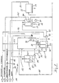
- in schematischer Darstellung ein Fließbild einer Vorrichtung zum Reinigen bzw. Destillieren von im wesentlichen organisch belasteten Abwässern und
- Figur 2
- in vergrößerter Darstellung denjenigen Teil der Vorrichtung ,der das Zweikreis-Prozeßsystem beinhaltet, zusammen mit einem Abschlämmbehälter.
- Figure 1
- a schematic representation of a flow diagram of a device for cleaning or distilling substantially organically contaminated wastewater and
- Figure 2
- in an enlarged view that part of the device which contains the two-circuit process system, together with a blowdown tank.
Die in der Zeichnung gemäß einem bevorzugten Ausführungsbeispiel vorliegender Erifndung dargestellte Vorrichtung 11 dient zum Reinigen bzw. Destillieren von organisch belasteten Abwässern, wie sie bspw. in entsprechenden Industriebetrieben anfallen. Beim dargestellten Ausführungsbeispiel wird ein Zweikreissystem 12 mit einem Primärsystem 13 für das zu behandelnde Abwasser und einem räumlich davon getrennten in sich geschlossenen Sekundärsystem 14 verwendet, das unter Überdruck gefahren wird. Es versteht sich, daß es auch möglich ist, ein Zweikreissystem 12 zu verwenden, bei dem im Vakuum verdampft wird.The
Gemäß Figur 1 wird über eine von einer nicht dargestellten Industrieanlage kommenden Rohrleitung 16 zu behandelndes Abwasser einem ersten Vorlagebehälter 17 zugefuhrt, der mit einem motorisch angetriebenen Rührwerk 18 versehen ist, damit sich keine festen Bestandteile in dem zu behandelnden Abwasser am Behälterboden absetzen können und die Wärmeverteilung verbessert wird. Das Abwasser wird in einer Rohrleitung 19 über eine Pumpe 21 einer Filterpresse 22 zugeführt, deren Filterkuchen 23 in im wesentlichen feuchter Form diejenigen Feststoffe enthält, die aus dem Abwasser durch Filtration separiert werden können. Dieser Filterkuchen 23 kann dann an einer Deponie abgelagert oder weiter entsorgt werden. Das Filtrat bzw. filtrierte Abwasser wird dann über eine Rohrleitung 25 einem zweiten Vorlagebehälter 26 zugeführt, der ebenfalls mit einem motorischen Rührwerk 27 versehen ist. Über eine Ausgangleitung 28 und eine Pumpe 29 wird das filtrierte Abwasser in den Primärkreis 13 des Zweikreissystems 12 gespeist. Das Abwasser hat hier eine Temperatur von etwa 15 bis 20°C.According to FIG. 1, wastewater to be treated coming from an industrial plant, not shown, is fed to a
Während also das Primärsystem 13 des Zweikreis-Wärmepumpensystems 12 mit dem zu behandelnden filtrierten Abwasser gespeist wird, ist das in sich geschlossene Sekundärsystem 14 mit einer absperrbaren Rohrleitung 31 zum Zuführen von Speisewasser als Sekundärmedium verbunden. Im Primärsystem 13 ist außerdem, wie noch zu zeigen sein wird, eine Fremdheizung 32 installiert, die beim dargestellten Ausführungsbeispiel über eine Rohrleitung 33 mit Heizdampf versorgt wird. Es versteht sich, daß die Fremdheizung 32 auch elektrisch betreibbar ist.So while the
Bodenseitig ist das Primärsystem 13 des Zweikreissystems 12 mit einer absperrbaren Abzugsrohrleitung 36 versehen, die in einen Abschlämmbehälter 37 führt, welcher mit einem motorisch angetriebenen Rührwerk 38 versehen ist. Über die Abzugsrohrleitung 36 gelangt eingeengte Abwasser-Sumpflösung aus dem Primärsystem 13 gesteuert in den Abschlämmbehälter 37, wobei die Lösung beim dargestellten Ausführungsbeispiel über 100°C heiß ist. Diese heiße eingeengte Abwasser-Sumpflösung wird über einen mit einem Ventil 39 versehen Abzweig 40 der Rohrleitung 28 im Abschlämmbehälter 37 mit filtiriertem Abwasser vermischt, so daß ausgangsseitig eine Abwasserlösung von unter 100°C zu transportieren ist. Hierzu ist das Ventil 39 von einer kombinierten Temperatur/Füllstandssteuerung 49 gesteuert. Ausgangsseitig des Abschlämmbehälters 37, der mit einer Entlüftungsleitung 41 versehen ist, wird über eine druckluftbetriebene Pumpe 42 in einer Rohrleitung 43 diese Abwasserlösungsmischung dem ersten Vorlagebehälter 17 zugeführt und dort mit dem "frischen" Abwasser aus der Rohrleitung 16 vermischt und mit diesem wiederum der Filterpresse 22 zugeführt. In dem ersten Vorlagebehälter 17 ist eine Kühleinrichtung 44 vorgesehen, die über eine Rohrleitung 45 mit Kühlwasser gespeist wird. Die druckluftbetriebene Pumpe 42 erhält über eine Rohrleitung 46 Druckluft zugeführt, deren Abzweigleitung 47 dem Zweikreis-Wärmepumpensystem 12 zu deren Druchluftsteuerung zugeführt wird.At the bottom, the
Das ausgangsseitig des Primärsystems 13 des Zweikreissystems 12 erhältliche Destillat des gereinigten bzw. destillierten Abwassers wird über eine Ausgangsleitung 48, in die beim Ausführungsbeispiel die Kühlwasserleitung 45 der Kühleinrichtung 44 mündet, entweder einem Abwasserkanal oder dem Industrieprozeß als wiederverwendbares Rohwasser zugeführt. Das destillierte Abwasser besitzt dabei einen CSB (chemischer Sauerstoffbedarf)- Wert, der den wasserrechtlichen Forderungen entspricht. Das Kühlwasser in der Kühlwasserleitung 45 kann alternativ auch in den Kühlwasserkreislauf rückgeführt werden.The distillate of the cleaned or distilled wastewater obtainable on the output side of the
Im folgenden sei nun anhand der Figur 2 die Arbeitsweise des Zweikreissystems 12 beschrieben. Das durch die Rohrleitung 28 in das Primärsystem 13 eintretende Abwasser wird im Gegenstrom zum aus der Ausgangleitung 48 austretenden Destillat einem Vorwärmetauscher 51 bis knapp unterhalb der Destilliertemperatur vorgewärmt. Der Vorwärmetauscher 51 ist hier als spiralförmiger Doppelrohrwärmeübertrager ausgebildet. Vom Vorwärmetauscher 51 gelangt das gefilterte Abwasser in einen Sumpfbereich 53 eines ersten Wärmetauschers 52, der im Primärsystem 13 als Verdampfer arbeitet. Im Sumpfbereich 53 des ersten Wärmetauschers 52 ist die Fremdheizung 32 angeordnet,die im wesentlichen lediglich zum Anfahren des Prozesses aus dem kalten Zustand dient. Vom Sumpfbereich 53 aus steigt das zu behandelnde Abwasser in den Verdampferbereich 51 des ersten Wärmetauschers 52, der in Form eines Wellflächenverdampfers ausgebildet ist. Der in den Rohren des Verdampferbereichs 54 des ersten Wärmetauschers 52 erzeugte Abwasser- bzw. Destillatdampf steigt nach oben und passiert ein Zyklon 56, in welchem die Trennung von mitgerissenen Tröpfchen und Partikeln aufgrund einer sehr hohen Zentrifugalbeschleunigung des Dampfes staffindet. Durch einen physikalischen Effekt bildet sich zwischen Zykloninnenwand und dem Destillatdampf ein Wasserfilm, der den Vorteil hat, alle auszentrifugierten Tröpfchen und Partikel zu binden und selbst den Kontakt des Destillatdampfes mit der Wand zu verhindern. Da der Wasserfilm aufgrund des inneren Strömungsfeldes in den unteren Teil des Zyklons wandert, gelangt er nicht in das Destillat. Über ein bodenseitiges Rohr 57 wird das zusammenlaufende Wasser abgeführt und in den Abschlämmbehälter 37 rückgeführt. Der Destillatdampf selbst kommt nicht an den kritischen Stellen der höchsten Geschwindigkeit mit der Metallfläche in Berührung, sondern gelangt über das in der Mitte des Zyklons 56 angebrachte Tauchrohr 58 in einen zweiten Wärmetauscher 62, der im Primärsystem 13 als Kondensator wirkt. Wie in Figur 2 ausschnittsweise dargestellt ist, ist dieser zweite Wärmetauscher 62 in Form eines Wellflächenverdampfers/-kondensators ausgebildet, bei dem der aus dem Zyklon 56 austretende Dampf nach einer Richtungsänderung um 90° Spalträume 61 zwischen aufrechten Wellflächenplatten 64 durchströmt und dabei kondensiert. Das Kondensat, in Form des Abwasserdestillats, verläßt durch den Vorwärmetauscher 51 und die Ausgangsleitung 48 das Primärsystem 13.The mode of operation of the dual-
Die im Primärsystem 13 an dem als Kondensator wirkenden zweiten Wärmetauscher 62 freiwerdende Kondensationswärme des Primärmediums (zu reinigendes Abwasser bzw. Abwasserdampf) wird benutzt, um hier im Sekundärsystem 14 eine Verdampfung des Sekundärmediums, das hier Rohwasser ist, durchzuführen. Dieses Rohwasser wird nur einmal in das Sekundärsystem 14 eingespeist. Der entstehende Rohwasserdampf im Sekundärsystem 14 wird über einen nicht dargestellten herkömmlichen Tropfenabscheider vom oberen Teil des Zweikreissystems 12 in einen Verdichter 66 geführt. der elektrisch angetrieben ist. Im Verdichter 66 findet eine Kompression und eine damit verbundene Temperaturerhöhung statt. Der den Verdichter verlassende Dampf des Sekundärmediums ist heiß genug, um im ersten Wärmetauscher 52, der im Sekundärsystem 14 als Verdampfer wirkt im wesentlichen als alleiniges Heizmedium zum Verdampfen des vorerwärmten gefilterten Abwassers zu dienen. Eine Energiezuführung über die Fremdheizung 32 ist in diesem Betriebszustand nur noch nötig, um den Wärmeverlust durch die heiße, abgeschlämmte Abwasser-Sumpflösung zu decken. Durch die Kondensation des Dampfes des Sekundärmediums im ersten Wärmetauscher 52 wird in diesem das Abwasser verdampft. Das anfallende Kondensat des Sekundärmediums verläßt den ersten Wärmetauscher 52 und gelangt über ein Rohr 68 und über ein Drosselventil 65 in den oberen zweiten Wärmetauscher 62, der im Sekundärsystem 11 als Verdampfer arbeitet. Das Kondensat des Sekundärmediums strömt in einen Bodenbereich des zweiten Wärmetauschers 62 ein und strömt als Dampf durch die Rohrräume 63 der Wellflächenplatten 64 senkrecht nach oben in einen Auffangraum 70 und von dort über das Rohr 67 zurück zum Verdichter 66. Es versteht sich, daß die beiden Systeme 13 und 14 vollkommen voneinander getrennt sind und daß in entsprechender Weise der dargestellte Wellflächenplatten-Wärmetauscher 62 ausgebildet ist. Wenn auch in schematisch anderer Weise dargestellt, so kann der erste Wärmetauscher 52 abenfalls eine derartige Konstruktion besitzen.The heat of condensation of the primary medium (waste water or waste water vapor to be cleaned) which is released in the
Da das zu reinigende bzw. zu destillierende Abwasser im wesentlichen organisch belastet ist und daher ein Vielstoffgemisch mit verschiedenen Problemstoffen darstellt, wie bspw. niedersiedende Bestandteile, schaumbildende Bestandteile usw., ist die Vorrichtung 11 mit einer Regeleinrichtung 71 ausgestattet , die einen kontiuierlichen Prozeßablauf ermöglicht, unabhängig davon, wie hoch die organische Belastung ist und welche Problemstoffe in welchen Anteilen darin enthalten sind. Dazu ist eine erste Regeleinheit 72 vorgesehen, die einerseits mit einem Überhitzungstemperaturfühler 73 und andererseits mit einem Antrieb 74 des Ventils 39 in der Abzugsrohrleitung 36 verbunden ist. Der Temperaturfühler 73 erfaßt die Überhitzungstemperatur des Sekundärmediums im Sekundärsystem 14 an der Druckseite des Verdichters 66, während das Ventil 39 den Abzug von eingeengter Abwasser-Sumpflösung aus dem Sumpfbereich 53 des ersten Wärmetauschers 52 dann freigibt, wenn bspw. die Abwasser-Sumpflösung derart konzentriert ist, daß die gewünschten Verdampfungswerte des Abwassers nicht mehr erreicht werden. Dieses Maß an Abwasserdampf ist ein Maß für die Funktion des zweiten Wärmetauschers 62 und damit des Betriebszustands des Sekundärsystems 14, dessen bei einer Verschlechterung des Wärmeübergangs verringerter Massenstrom durch eine Druckerhöhung des Verdichters 66 kompensiert werden muß, was eine Erhöhung der Überhitzungstemperatur am druckseitigen Ausgang des Verdichters 66 zur Folge hat. Aus diesem Grunde ist der Temperaturfühler 73 unmittelbar am Druckausgang des Verdichters 66 angeordnet. Erhöht sich also die Überhitzungstemperatur über einen gewünschten Sollwert oder Sollwertbereich, so wird in Abhängigkeit davon die erste Regeleinheit 72 den Antrieb 74 des Ventils 39 ansteuern und dieses zum Abziehen von Abwasser-Sumpflösung öffnen. Das Öffnen des Ventils 39 erfolgt dabei getaktet, vorzugsweise in gleichmäßigen kurzen Intervallen. Die mit dem Ventil 39 versehene Rohrleitung 36 ist durchmessergroß und möglichst kurz und mündet geradlinig in den unmittelbar unter dem Sumpfbereich 53 des ersten Wärmetauschers 52 stehenden Abschlämmbehälter 37.Since the wastewater to be cleaned or distilled is essentially organically contaminated and is therefore a multi-substance mixture with various problematic substances, such as low-boiling constituents, foam-forming constituents, etc., the
Die Regeleinrichtung 71 besitzt eine zweite Regleinheit 76, die einerseits mit einer Füllstandssonde 77 und andererseits mit der Förderpumpe 29 für das zu destillierende Abwasser und/oder gemäß Figur 2 mit einem Antrieb 78 eines Zulaufventils 79 in der Zulaufleitung 28 verbunden ist. Die zweite Regeleinheit 76 dient einerseits dazu, den Zufluß von zu destllierendem Abwasser dann zu ermöglichen, wenn ein entsprechender Anteil an Abwasser im ersten Wärmetauscher 52 verdampft ist; sie dient aber auch dazu, den Füllstand des Abwassers im ersten Wärmetauscher 52 auf den gewünschten Wert dann zu bringen, wenn aus dem Sumpfbereich 53 des ersten Wärmetauschers 51 eingeengte Abwasser-Sumpflösung abgezogen worden ist. Auch die zweite Regeleinheit 76 ist derart ausgebildet, daß sie das Zulaufventil 79 (bzw. die Pumpe 29) getaktet, vorzugsweise in gleichmäßigen kurzen Intervallen, öffnet und schließt. Dies hat einerseits zur Folge, daß die Wärmebilanz innerhalb des Primärsystems 13 bzw. des gesamten Zweikreissystems 12 ohne größere Änderungen bleibt, und andererseits, daß die schaumbildenden Bestandteile im zu destillierenden Abwasser keinen Schaum innerhalb des ersten Wärmetauschers 52 in einem Ausmaß bilden können, der die Wärmebilanz im System und/oder die Füllstandsmessung stören könnte. Die zweite Regeleinneit 76 wird also dann, wenn die erste Regeleinheit 72 in Betrieb ist und das Ventil 79 getaktet öffnet und schließt, dieser unmittelbar folgen und ein getaktetes Zuströmen des zu reinigenden Abwassers ermöglichen.The
Üblicherweise sind in organisch belasteteten Abwässern mehr oder weniger große Anteiie an niedersiedenden Bestandteilen, wie Inertgase vorhanden. Diese Gase, die leichter als. Wasserdampf sind, werden bei der Kondensation des Abwasserdampfes im zweiten Wärmetauscher 62 ausgasen und sich an einer strömungstechnisch urgünstigen Stelle, wie bspw. der mit 81 bezeichneten Stelle absetzen. Derartige Gasnester 81 sind, wenn sie sich vergrößern, nachteilig für die Wärmebilanz des zweiten Wärmetauschers 62 deshalb, weil sich diese leichteren Gase wie ein Wärmeisolator über die Wärmetauscherflächen des zweiten Wärmetauschers 62 legen und damit einen Wärmeaustausch erschweren bzw. herabsetzen. Um dies zu verhindern, ist in diesem Bereich 81 eine Entlüftungsleitung 82 vorgesehen. Diese Entlüftungsleitung 82 kann ständig offen sein. Beim Ausführungsbeispiel jedoch ist ein Ventil 83 vorgesehen, dessen Antrieb 84 mit der ersten Regeleinheit 72 verbunden ist. Da eine Verschlechterung der Wärmebilanz des Primärsystems 13 und damit auch des Sekundärsystems 14 nicht nur von der Konzentration der Abwasser Sumpflösung abhängig ist, sondern auch von dem Ausmaß und Umfang der Gasnester 81 abhängig sein kann, ist damit erreicht, daß mit einem Erfassen einer Wärmebilanzinstabilität aufgrund einer Erhöhung der Überhitzungstemperatur im Sekundärsystem 14 auch das oder die Gasnester 81 entlüftet werden. Dieser Entlüftungsvorgang erfolgt zweckmäßigerweise kontinuierlich über eine bestimmte Zeitdauer.Usually, organically polluted wastewater contains more or less large amounts of low-boiling components, such as inert gases. These gases that are lighter than. Are water vapor, are outgassed in the condensation of the waste water vapor in the
Diejenigen Gase, die schwerer als Wasserdampf sind, werden sich mit dem kondensierenden Wasserdampf am Boden 86 des zweiten Wärmetauschers 62 niederschlagen und aufgrund der hohen Temperatur von bspw. 124°C des Wasserdestillats nicht wieder in diesem lösen. Diese Gase werden in der dargestellten Weise über eine obere Leitung 87 in einen Zwischenbehälter 88 strömen und dort über einen Auslaß 89 ständig entlüftet werden, während das Destillat über eine untere Leitung 91 in den Zwischenbehälter 88 und von dort in die Ausgangsleitung 48 abfließen kann.Those gases that are heavier than water vapor will precipitate with the condensing water vapor at the bottom 86 of the
Als Kriterium für die Einleitung von Abwasser in öffentliche kläranlagen gibt es neben dem Summenparamter CSB zusätzlich den Grenzwert des Ammoniumgehaltes des Abwassers. Um den Ammoniumgehalt im Destillat zu reduzieren, wird mittels einer Pumpe 94 über eine Rohrleitung 93, an deren in dem Tauchrohr 58 des Zyklons 56 angeordnetes Ende eine Düse 92 angeordnet ist, z.B. saure, wässrige Ammoniumsulfatlösung oder wässerige Schwefelsäurelösung od. dgl. im Gegenstrom zur Bewegungsrichtung des Abwasserdampfes in das Tauchrohr 58 des Zyklons 56 vorzüglich kontinuierlich eingesprüht.As a criterion for the discharge of wastewater into public wastewater treatment plants, in addition to the total parameter COD there is also the limit value of the ammonium content of the wastewater. In order to reduce the ammonium content in the distillate, a
Das im Abwasserdarnpf befindliche Ammoniak oder Ammonium (in Wassertröpfchen) kommt so mit der eingesprühten Lösung in Kontakt und wird mit ihr zur Zyklonwand hin ausgeschleudert. Über die dabei ablaufenden Reaktionen bilden sich Salzlösungen. Diese werden aus dem Zyklon über das bodenseitige Rohr 57 entweder nur nach außen oder wieder in den Abschlämmbehälter 37 geführt. Um die so abgeführte Ammoniummenge reduziert sich der Gehalt an Ammonium im Destillat. Eine derartige Wäsche des aus dem Zyklon austretenden Abwasserdampf wird auch unabhängig von der weiteren erfindungsgemäßen Regelungsmaßnahmen möglich.The ammonia or ammonium (in water droplets) in the waste water dam comes in contact with the sprayed solution and is ejected with it towards the cyclone wall. Salt solutions are formed via the reactions taking place. These are fed out of the cyclone via the bottom-
Das erfindungsgemäße Verfahren und die erfindungsgemäße Vorrichtung 11 wurden anhand eines Zweikreissystems 12 beschrieben, in welchem die Verdampfungs- und Kondensationsschritte im Überdruck erfolgen. Es versteht sich, daß zur Reinigung bzw. Destillation von im wesentlichen organisch belasteten Abwässern auch eine Vakuumverdampfung stattfinden kann. Bei der Erfassung eines Betriebsparameters im Sekundärkreis 14, welcher Parameter eine Prozeßinstabilität im Primärsystem und damit im Sekundärsystem anzeigt, kann als ein solcher statt die Überhitzungstemperatur auch die Stromaufnahme des elektrischen Antriebs des Verdichters 66 gewählt werden. Es ist deshalb möglich, die erste Regeleinheit 72 statt mit einem Überhitzungstemperaturfühler mit einem Meßgerät zum Messen der Stromaufnahme des elektrischen Verdichterantriebs zu verbinden.The method according to the invention and the
Claims (15)
- A process for purifying substantially organically polluted waste water in particular, where the waste water is evaporated and condensed within a primary system and a secondary medium, preferably raw water, is evaporated and condensed within a closed secondary system containing a compressor and being spatially separated from the primary system, where the waste water is evaporated by heating by the secondary medium which was previously further heated in the compressor, and the secondary medium is evaporated in the secondary system by condensation of the waste water vapor, and where the waste water vapor is conducted through a cyclone and the concentrated waste water sump solution generated during the evaporation of the waste water is drawn off, characterized in that the concentrated waste water sump solution is drawn off as a function of an operational parameter of the secondary system at a time when the latter exceeds a set value range, and that the waste water is admitted as a function of the fill level in the primary system.
- A process in accordance with claim 1, characterized in that the overheating temperature of the secondary medium at the pressure side of the compressor is used as the operational parameter.
- A process in accordance with claim 1, characterized in that the current intake of the compressor is used as the operational parameter.
- A process in accordance with at least one of claims 1 to 3, characterized in that the waste water sump solution is drawn off in cycles, preferably in even intervals.
- A process in accordance with at least one of claims 1 to 4, characterized in that gases, which are lighter than the waste water vapor and collect during the waste water condensation at one or a plurality of place(s) unfavorable from the viewpoint of flow technology, such as insert gases, are exhausted.
- A process in accordance with claim 5, characterized in that the exhaust of the lighter gases is performed prallel with the draw-off of the waste water sump solution.
- A process in accordance with at least one of the previous claims, characterized in that acid aqueous ammonium sulfate solution or aqueous sulfuric acid solution is sprayed into the cyclone in counterflow to the direction of movement of the waste water vapor.
- A device for purifying substantially organically polluted waste water in particular, comprising a primary system (13) for the waste water and a closed secondary system (14), spatially separated therefrom and containing a compressor (66), for heat transfer, where the primary system (13) is coupled with the secondary system by means of a first heat exchanger (52) for evaporating the waste water and a second heat exchanger (62) for condensing the waste water vapor, and comprising a cyclone (56) disposed in the vapor chamber between the evaporator and the condenser, characterized by a first control unit (72) which opens or closes a draw-off opening in the bottom area (53) of the first heat exchanger (52) for drawing off concentrated waste water sump solution as a function of a measured value of an operational parameter of the secondary system (14), and by a second control unit (76), which opens or blocks the admission of waste water as a function of measured value of the fill level in the primary system (13).
- A device in accordance claim 8, characterized in that the first control unit (72) is connected with an overheating temperature sensor (73), which is disposed directly at the pressure side of the compressor (66).
- A device in accordance with claim 8, characterized in that the first control unit (72) is connected with a device for measuring the current intake of the electric motor of the compressor (66).
- A device in accordance with at least one of claims 8 to 10, characterized in that the opening and closing of the draw-off opening for the waste water sump solution is cycled in preferably even intervals.
- A device in accordance with at least one of claims 8 to 11, characterized in that the draw-off opening is diameter-sized and is connected via a short pipeline (36) with an elutriation container (37) located directly under it.
- A device in accordance with at least one of claims 8 to 12, characterized in that the second heat exchanger (62) is provided, at one or a plurality of places (81) unfavorable from the viewpoint of flow technology, with an exhaust opening (82) for gases which are lighter than the waste water vapor, such as inert gases.
- A device in accordance with at least one of claims 8 to 10, characterized in that the exhaust opening (82) for the lighter gases is provided with a valve (83), which is connected with the first control unit (72).
- A device in accordance with at least one of claims 8 to 14, characterized in that the end of a pipeline (93) provided with a spray nozzle (92) is directed into the cyclone (56), by means of which acid aqueous ammonium sulfate solution or aqueous sulfuric acid solution can be prayed in counterflow to the direction of movement of the waste water vapor.
Priority Applications (1)
| Application Number | Priority Date | Filing Date | Title |
|---|---|---|---|
| AT90916279T ATE100782T1 (en) | 1989-11-11 | 1990-11-09 | PROCESS FOR PURIFYING ORGANIC WASTEWATER. |
Applications Claiming Priority (2)
| Application Number | Priority Date | Filing Date | Title |
|---|---|---|---|
| DE19893937608 DE3937608C1 (en) | 1989-11-11 | 1989-11-11 | |
| DE3937608 | 1989-11-11 |
Publications (2)
| Publication Number | Publication Date |
|---|---|
| EP0508986A1 EP0508986A1 (en) | 1992-10-21 |
| EP0508986B1 true EP0508986B1 (en) | 1994-01-26 |
Family
ID=6393366
Family Applications (1)
| Application Number | Title | Priority Date | Filing Date |
|---|---|---|---|
| EP90916279A Expired - Lifetime EP0508986B1 (en) | 1989-11-11 | 1990-11-09 | Process for purifying organically polluted waste water |
Country Status (3)
| Country | Link |
|---|---|
| EP (1) | EP0508986B1 (en) |
| DE (1) | DE3937608C1 (en) |
| WO (1) | WO1991007353A1 (en) |
Families Citing this family (8)
| Publication number | Priority date | Publication date | Assignee | Title |
|---|---|---|---|---|
| US5512142A (en) * | 1989-11-11 | 1996-04-30 | Hoiss; Jakob | Process and device for purifying organically polluted waste water |
| DE4128992C1 (en) * | 1991-08-31 | 1992-09-24 | Jakob Dr.-Ing. 8000 Muenchen De Hoiss | |
| SE514157C2 (en) | 1999-04-20 | 2001-01-15 | Nivell System Ab | Building construction for floors, walls or ceilings including rules fitted with level setting screws and rules therefore |
| FR2809385A1 (en) * | 2000-05-26 | 2001-11-30 | Tsb Internat | METHOD AND INSTALLATION FOR PURIFICATION AND DESALINATION OF SEA WATER |
| DE10122230B4 (en) * | 2001-05-08 | 2009-04-02 | Jürgen Kiessling | Method and device for controlling the liquid balance of an evaporation plant |
| DE102009031246A1 (en) * | 2009-01-29 | 2010-08-05 | Peter Szynalski | System for the desalination of seawater, comprises an evaporation body, a first line system, which guides salt-containing raw water to the evaporation body, a heater arranged to the evaporation body, and a second line system |
| DE102020213158A1 (en) | 2020-10-19 | 2022-04-21 | Robert Bosch Gesellschaft mit beschränkter Haftung | Magnetocaloric distillation unit |
| CN114661074B (en) * | 2022-05-24 | 2022-09-20 | 深圳市家家分类科技有限公司 | Liquid level control method and device |
Family Cites Families (6)
| Publication number | Priority date | Publication date | Assignee | Title |
|---|---|---|---|---|
| DE199341C (en) * | ||||
| US3840437A (en) * | 1972-07-17 | 1974-10-08 | Continental Oil Co | Distillation column control method and system |
| US3905873A (en) * | 1973-09-24 | 1975-09-16 | Standard Oil Co Ohio | Control apparatus for fractionation tower |
| DE2600398C2 (en) * | 1976-01-07 | 1985-01-10 | Jakob Dr.-Ing. 8000 München Hoiß | Process and device for raw water distillation |
| DE2920212A1 (en) * | 1979-05-18 | 1980-11-20 | Linde Ag | DEVICE FOR PRODUCING HIGH PURITY WATER |
| DE3214647A1 (en) * | 1982-04-21 | 1983-10-27 | J.F. Adolff Ag, 7150 Backnang | Process and plant for treating dirty water |
-
1989
- 1989-11-11 DE DE19893937608 patent/DE3937608C1/de not_active Expired - Lifetime
-
1990
- 1990-11-09 WO PCT/EP1990/001873 patent/WO1991007353A1/en active IP Right Grant
- 1990-11-09 EP EP90916279A patent/EP0508986B1/en not_active Expired - Lifetime
Non-Patent Citations (1)
| Title |
|---|
| Zeitschrift für wirtschaftliche Fertigung, Volume 79, no. 3, 1984 J. Hoiss: "Recycling von nitrat-nitrithaltigen Spülwässern aus Härtereibetrieben", see page 141, 145 * |
Also Published As
| Publication number | Publication date |
|---|---|
| EP0508986A1 (en) | 1992-10-21 |
| WO1991007353A1 (en) | 1991-05-30 |
| DE3937608C1 (en) | 1990-08-09 |
Similar Documents
| Publication | Publication Date | Title |
|---|---|---|
| WO1996007460A1 (en) | Process and device for desalinating sea water | |
| DE19629500C1 (en) | Multi-scrubber and process for the total purification of gases | |
| DE102011082769A1 (en) | Method and device for degassing a PET plastic melt in an extrusion plant | |
| EP1363855B1 (en) | Method and device for treating liquids | |
| DE2451157A1 (en) | PROCESS FOR SEPARATING EXHAUST AIR CARBON HYDROCARBONS AND EQUIPMENT FOR CARRYING OUT THE PROCESS | |
| WO2007107260A1 (en) | Process for removing volatile components from a substance mixture and apparatus for performing this process | |
| DE3639958A1 (en) | MULTI-STAGE COUNTERFLOW ARRANGEMENT AND RELATED PROCEDURES | |
| EP0508986B1 (en) | Process for purifying organically polluted waste water | |
| DE10325230A1 (en) | Small-scale effluent water treatment process and assembly exposes vapor to intense ultraviolet light | |
| CH624479A5 (en) | ||
| EP3448813B1 (en) | Sea water desalination device for desalinating sea water | |
| DE3935892C2 (en) | Method and device for concentrating a liquid containing sulfuric acid and water | |
| WO2003068358A1 (en) | Method and device for the treatment of waste water | |
| DE3509782C2 (en) | ||
| DD300228A5 (en) | Process for producing organic waste and apparatus therefor | |
| DE102016214019A1 (en) | Device for separating product water from contaminated raw water and method for operating this device | |
| DE19715839A1 (en) | Process and device for cleaning oil and water-containing mill scale sludges | |
| DE60013484T2 (en) | METHOD FOR CLEANING OBJECTS THROUGH A WARMED LIQUID, AND APPARATUS FOR CARRYING OUT THIS METHOD | |
| DE69930284T2 (en) | DEVICE FOR CLEANING A FLUID IN THE FORM OF STEAM FROM A CIRCULATION | |
| EP0035650B1 (en) | Continuous-evaporation plant for contaminated liquids | |
| EP0656322B1 (en) | Purification system | |
| DE102014112140B4 (en) | Method and device for treating wastewater from production or work processes | |
| EP0571408B1 (en) | Process and device for cleaning gases laden with noxious substances | |
| DE102019105353B4 (en) | Process for processing liquids containing ammonia and system for carrying out the process | |
| DE102009049823A1 (en) | Method for processing of water for the maintenance of rinsing baths in connection with wash baths, comprises producing fresh steam through indirect heat transfer, and heating and evaporating the processing water over a heat exchanger |
Legal Events
| Date | Code | Title | Description |
|---|---|---|---|
| PUAI | Public reference made under article 153(3) epc to a published international application that has entered the european phase |
Free format text: ORIGINAL CODE: 0009012 |
|
| 17P | Request for examination filed |
Effective date: 19920610 |
|
| AK | Designated contracting states |
Kind code of ref document: A1 Designated state(s): AT CH ES FR GB IT LI NL SE |
|
| 17Q | First examination report despatched |
Effective date: 19930401 |
|
| GRAA | (expected) grant |
Free format text: ORIGINAL CODE: 0009210 |
|
| AK | Designated contracting states |
Kind code of ref document: B1 Designated state(s): AT CH ES FR GB IT LI NL SE |
|
| PG25 | Lapsed in a contracting state [announced via postgrant information from national office to epo] |
Ref country code: IT Free format text: LAPSE BECAUSE OF FAILURE TO SUBMIT A TRANSLATION OF THE DESCRIPTION OR TO PAY THE FEE WITHIN THE PRE;WARNING: LAPSES OF ITALIAN PATENTS WITH EFFECTIVE DATE BEFORE 2007 MAY HAVE OCCURRED AT ANY TIME BEFORE 2007. THE CORRECT EFFECTIVE DATE MAY BE DIFFERENT FROM THE ONE RECORDED.SCRIBED TIME-LIMIT Effective date: 19940126 Ref country code: ES Free format text: THE PATENT HAS BEEN ANNULLED BY A DECISION OF A NATIONAL AUTHORITY Effective date: 19940126 Ref country code: GB Effective date: 19940126 Ref country code: FR Effective date: 19940126 Ref country code: SE Effective date: 19940126 Ref country code: NL Effective date: 19940126 |
|
| REF | Corresponds to: |
Ref document number: 100782 Country of ref document: AT Date of ref document: 19940215 Kind code of ref document: T |
|
| EN | Fr: translation not filed | ||
| NLV1 | Nl: lapsed or annulled due to failure to fulfill the requirements of art. 29p and 29m of the patents act | ||
| GBV | Gb: ep patent (uk) treated as always having been void in accordance with gb section 77(7)/1977 [no translation filed] |
Effective date: 19940126 |
|
| PLBE | No opposition filed within time limit |
Free format text: ORIGINAL CODE: 0009261 |
|
| STAA | Information on the status of an ep patent application or granted ep patent |
Free format text: STATUS: NO OPPOSITION FILED WITHIN TIME LIMIT |
|
| 26N | No opposition filed | ||
| PGFP | Annual fee paid to national office [announced via postgrant information from national office to epo] |
Ref country code: AT Payment date: 19971121 Year of fee payment: 8 |
|
| PGFP | Annual fee paid to national office [announced via postgrant information from national office to epo] |
Ref country code: CH Payment date: 19971126 Year of fee payment: 8 |
|
| PG25 | Lapsed in a contracting state [announced via postgrant information from national office to epo] |
Ref country code: AT Free format text: LAPSE BECAUSE OF NON-PAYMENT OF DUE FEES Effective date: 19981109 |
|
| PG25 | Lapsed in a contracting state [announced via postgrant information from national office to epo] |
Ref country code: CH Free format text: LAPSE BECAUSE OF NON-PAYMENT OF DUE FEES Effective date: 19981130 Ref country code: LI Free format text: LAPSE BECAUSE OF NON-PAYMENT OF DUE FEES Effective date: 19981130 |
|
| REG | Reference to a national code |
Ref country code: CH Ref legal event code: PL |