EP0508965A1 - Dosage device for colour-powder, -grains or -microparticles - Google Patents
Dosage device for colour-powder, -grains or -microparticles Download PDFInfo
- Publication number
- EP0508965A1 EP0508965A1 EP19920830171 EP92830171A EP0508965A1 EP 0508965 A1 EP0508965 A1 EP 0508965A1 EP 19920830171 EP19920830171 EP 19920830171 EP 92830171 A EP92830171 A EP 92830171A EP 0508965 A1 EP0508965 A1 EP 0508965A1
- Authority
- EP
- European Patent Office
- Prior art keywords
- dye
- container
- shutter
- scraper
- balance
- Prior art date
- Legal status (The legal status is an assumption and is not a legal conclusion. Google has not performed a legal analysis and makes no representation as to the accuracy of the status listed.)
- Granted
Links
Images
Classifications
-
- B—PERFORMING OPERATIONS; TRANSPORTING
- B65—CONVEYING; PACKING; STORING; HANDLING THIN OR FILAMENTARY MATERIAL
- B65G—TRANSPORT OR STORAGE DEVICES, e.g. CONVEYORS FOR LOADING OR TIPPING, SHOP CONVEYOR SYSTEMS OR PNEUMATIC TUBE CONVEYORS
- B65G65/00—Loading or unloading
- B65G65/30—Methods or devices for filling or emptying bunkers, hoppers, tanks, or like containers, of interest apart from their use in particular chemical or physical processes or their application in particular machines, e.g. not covered by a single other subclass
- B65G65/34—Emptying devices
- B65G65/40—Devices for emptying otherwise than from the top
- B65G65/48—Devices for emptying otherwise than from the top using other rotating means, e.g. rotating pressure sluices in pneumatic systems
- B65G65/4809—Devices for emptying otherwise than from the top using other rotating means, e.g. rotating pressure sluices in pneumatic systems rotating about a substantially vertical axis
- B65G65/4836—Devices for emptying otherwise than from the top using other rotating means, e.g. rotating pressure sluices in pneumatic systems rotating about a substantially vertical axis and moving material over a stationary surface, e.g. sweep arms or wheels
Abstract
Description
La présente invention concerne un dispositif pour le dosage de colorants en poudre, grains ou microperles, spécialement pour l'industrie textile, de la tannerie ou du papier.The present invention relates to a device for dosing powder, grain or microbead dyes, especially for the textile, tanning or paper industry.
On connaît d'après le document DE-U-9 014 270, un dispositif pour recueillir et distribuer des matières en poudre, lequel, dans la version illustrée dans les figures 1-3, comprend une plaque pourvue de plusieurs orifices à travers lesquels on fait passer la substance au moyen d'un collecteur muni d'une palette tournant autour d'un arbre vertical entra né par un organe moteur correspondant. Un plan situé au-dessous de la plaque perforée précitée permet de recueillir la matière ainsi tamisée, et une pale en forme de faux actionnée par ledit arbre vertical permet d'amener la matière recueillie dans un conduit central de sortie.
Mais ce dispositif ne permet pas le réglage de la taille des grains de la matière tamisée et, par ailleurs, il ne permet pas de régler rapidement le débit de la matière traitée, ce qui réduit fortement son degré de souplesse et limite son utilisation à des applications dans lesquelles il n'est pas nécessaire de changer rapidement la quantité de matière traitée, comme par exemple le transfert de matière d'un silo à un autre ou encore son conditionnement.
Il est également connu, d'après le même document, un dispositif pour recueillir une matière en grains, lequel, dans la version illustrée dans les figures 4-6, est pourvu d'une pluralité d'éléments plats, entra nés horizontalement et alternativement dans les deux sens, lesquels dirigent la matière à traiter dans des fentes diagonales correspondantes ou dans des trous correspondants d'une plaque. Pour le réglage de la taille des grains de la matière traitée, une deuxième plaque perforée est disposée au-dessous du premier de manière que les trous ou fentes des deux plaques correspondent exactement ou seulement partiellement.
Mais ce dispositif n'est pas en mesure lui non plus de garantir le degré de souplesse nécessaire pour les applications qui nécessitent de manière continue des variations rapides du débit de la matière à la sortie du dispositif.
La présente invention a pour but principal d'éliminer les inconvénients précités.Document DE-U-9 014 270 discloses a device for collecting and distributing powdered materials, which, in the version illustrated in Figures 1-3, comprises a plate provided with several orifices through which passes the substance by means of a collector provided with a pallet rotating around a vertical shaft entered by a corresponding drive member. A plane located below the aforementioned perforated plate makes it possible to collect the material thus screened, and a blade in the shape of a scythe actuated by said vertical shaft makes it possible to bring the material collected into a central outlet duct.
However, this device does not allow adjustment of the grain size of the sieved material and, moreover, it does not allow rapid adjustment of the flow rate of the treated material, which greatly reduces its degree of flexibility and limits its use to applications in which it is not necessary to quickly change the quantity of material treated, such as for example the transfer of material from one silo to another or its packaging.
It is also known, from the same document, a device for collecting a grain material, which, in the version illustrated in Figures 4-6, is provided with a plurality of flat elements, entered horizontally and alternately in both directions, which direct the material to be treated into corresponding diagonal slots or into corresponding holes in a plate. For adjusting the grain size of the treated material, a second perforated plate is arranged below the first so that the holes or slots in the two plates correspond exactly or only partially.
However, this device is also not capable of guaranteeing the degree of flexibility necessary for applications which continuously require rapid variations in the flow rate of the material leaving the device.
The main object of the present invention is to eliminate the aforementioned drawbacks.
Ce résultat a été atteint conformément à l'invention en adoptant l'idée de réaliser un dispositif pour le dosage de matières en poudre, grains ou microperles, spécialement des colorants et comprenant des moyens pour contenir le colorant; des moyens pour le compactage et l'expulsion du colorant hors des moyens pour contenir le colorant; des moyens pour la séparation des particules du colorant à la sortie des moyens pour contenir le colorant; des moyens pour le dosage du colorant qui a été traité; dans lequel lesdits moyens pour contenir le colorant sont constitués par un recipient cylindrique vertical con un orifice latéral pour l'entrée du colorant, avec une chambre supérieure, qui communique avec le récipient par l'intermédiaire d'une trémie, et avec des moyens d'aspiration à partir de ladite chambre supérieure; et ce dispositif étant pourvu de moyens de pesage du colorant en sortie et d'un ordinateur électronique pour le contrôle et la commande pour la gestion des fonctions remplies par tous les moyens précités.This result was achieved in accordance with the invention by adopting the idea of producing a device for dosing powdered materials, grains or microbeads, especially dyes and comprising means for containing the dye; means for compacting and expelling the dye out of the means for containing the dye; means for separating the particles of the dye at the outlet of the means for containing the dye; means for dosing the dye which has been treated; wherein said means for contain the dye are constituted by a vertical cylindrical container con a lateral opening for the entry of the dye, with an upper chamber, which communicates with the container via a hopper, and with means of aspiration from said upper chamber; and this device being provided with means for weighing the dye at the outlet and with an electronic computer for monitoring and control for the management of the functions fulfilled by all of the aforementioned means.
Les avantages obtenus grâce à la présente invention consistent essentiellement dans le fait qu'il est possible de régler avec continuité, rapidité et une grande précision la quantité du colorant traité, même s'il se présente sous forme de poudre très fine et avec des variations de poids allant d'un millième à un centième de gramme; qu'il est possible de garantir un degré de fiabilité élevé même après une longue période de fonctionnement.The advantages obtained thanks to the present invention essentially consist in the fact that it is possible to adjust with continuity, speed and great precision the quantity of the dye treated, even if it is in the form of a very fine powder and with variations. weighing from one thousandth to one hundredth of a gram; that a high degree of reliability can be guaranteed even after a long period of operation.
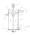
Ces avantages et caractéristiques de l'invention ainsi que d'autres seront plus et mieux compris de chaque homme du métier à la lumière de la description qui va suivre et à l'aide du dessin annexé donné à titre d'exemplification pratique de l'invention, mais à ne pas considérer dans le sens limitatif; dessin sur lequel l'unique figure représente la vue en coupe longitudinale d'un dispositif selon l'invention. Réduit à sa structure essentielle et en référence à la Figure du dessin annexé, un dispositif pour le dosage de colorants en poudre, grains ou microperles comprend:
- un récipient (1) pour recueillir le colorant à traiter approvisionné à partir d'un réservoir à travers un conduit d'entrée (8);
- un tamis (5) à grille, monté fixe à la base du récipient (1) avec un racleur (2) disposé au-dessus et entra né en rotation au moyen d'un moteur électrique (4) avec arbre (3) pour le compactage et l'expulsion du colorant;
- un obturateur (6) du type à compas, monté au-dessous du tamis (5), pour le dosage du colorant à la sortie du récipient (1);
- une balance de précision (20) pour le pesage du colorant passant à travers l'orifice de l'obturateur (6);
- un ordinateur électronique (30) pour le contrôle et la commande de la vitesse de rotation du racleur (2), de l'ouverture de l'obturateur (6) et de la valeur du pesage de la balance (20).
- a container (1) for collecting the dye to be treated supplied from a reservoir through an inlet duct (8);
- a screen (5) with grid, fixedly mounted at the base of the container (1) with a scraper (2) arranged above and entered into rotation by means of an electric motor (4) with shaft (3) for the compacting and expelling the dye;
- a compass type shutter (6), mounted below the sieve (5), for dosing the dye at the outlet of the container (1);
- a precision balance (20) for weighing the dye passing through the orifice of the shutter (6);
- an electronic computer (30) for monitoring and controlling the speed of rotation of the scraper (2), the opening of the shutter (6) and the weighing value of the balance (20).
Le fonctionnement du dispositif est le suivant.
Le colorant introduit dans le récipient (1) à travers le conduit d'entrée (8), est minutieusement subdivisé en particules par le flux d'air engendré par l'aspirateur, lesquelles tombent sur le fond; à cet endroit, le racleur (2) permet de les comprimer et de les faire passer à travers les mailles du tamis (5). Le réglage de la quantité de colorant à la sortie du récipient (1) s'effectue aussi bien au moyen de l'obturateur (6), dont l'ouverture plus ou moins importante est commandée par la balance (20) en fonction du pesage qu'elle doit effectuer à chaque fois, qu'en réglant la vitesse de rotation du racleur (2) pour comprimer dans les trous du tamis (5) une quantité plus ou moins grande de colorant; ledit réglage étant commandé par l'ordinateur (30) qui est lui-même informé par un programme de gestion approprié.The operation of the device is as follows.
The dye introduced into the container (1) through the inlet duct (8) is carefully subdivided into particles by the air flow generated by the vacuum cleaner, which fall onto the bottom; at this point, the scraper (2) allows them to be compressed and passed through the mesh of the sieve (5). The quantity of dye at the outlet of the container (1) is adjusted both by means of the shutter (6), the opening of which is more or less significant is controlled by the balance (20) depending on the weighing that it must perform each time, that by adjusting the speed of rotation of the scraper (2) to compress in the holes of the sieve (5) a more or less large amount of dye; said adjustment being controlled by the computer (30) which is itself informed by an appropriate management program.
Claims (2)
caractérisé en ce que ledit récipient est pourvu d'une chambre supérieure (9) qui communique avec celui-ci par l'intermédiaire d'une trémie centrale (10) à axe vertical et avec un aspirateur externe, non représenté, par l'intermédiaire d'un conduit (7) muni d'un filtre (11); en ce que ledit tamis (5) est du type à grille et que ledit racleur (2) est entra né en rotation à vitesse réglable; et en ce que le dispositif est équipé de:
characterized in that said container is provided with an upper chamber (9) which communicates with it via a central hopper (10) with vertical axis and with an external vacuum cleaner, not shown, via a conduit (7) provided with a filter (11); in that said screen (5) is of the grid type and that said scraper (2) is rotated at adjustable speed; and in that the device is equipped with:
Applications Claiming Priority (2)
| Application Number | Priority Date | Filing Date | Title |
|---|---|---|---|
| ITPT910006A IT1250991B (en) | 1991-04-08 | 1991-04-08 | EQUIPMENT FOR THE GRADUAL DOSAGE OF POWDER DYES, GRANULES OR MICRO BEADS |
| ITPT910006 | 1991-04-08 |
Publications (2)
| Publication Number | Publication Date |
|---|---|
| EP0508965A1 true EP0508965A1 (en) | 1992-10-14 |
| EP0508965B1 EP0508965B1 (en) | 1995-07-05 |
Family
ID=11396950
Family Applications (1)
| Application Number | Title | Priority Date | Filing Date |
|---|---|---|---|
| EP92830171A Expired - Lifetime EP0508965B1 (en) | 1991-04-08 | 1992-04-07 | Dosage device for colour-powder, -grains or -microparticles |
Country Status (5)
| Country | Link |
|---|---|
| EP (1) | EP0508965B1 (en) |
| AT (1) | ATE124664T1 (en) |
| CA (1) | CA2065525C (en) |
| DE (1) | DE69203271D1 (en) |
| IT (1) | IT1250991B (en) |
Citations (5)
| Publication number | Priority date | Publication date | Assignee | Title |
|---|---|---|---|---|
| GB762433A (en) * | 1954-09-03 | 1956-11-28 | Simon Ltd Henry | Improvements in dust separating and collecting apparatus |
| FR2128058A1 (en) * | 1971-03-02 | 1972-10-20 | Union Gle Coop Agricoles | |
| DE2731798A1 (en) * | 1977-07-14 | 1979-01-25 | Rene Chambon | Material metering equipment from hopper - has three perforated plates in contact and sliding against each other to free central plate openings |
| DE9014270U1 (en) * | 1989-12-22 | 1990-12-20 | Schwedes, Joerg, Prof. Dr.-Ing. | |
| WO1991004933A1 (en) * | 1989-10-09 | 1991-04-18 | Bühler AG Maschinenfabrik | Micro-metering device |
-
1991
- 1991-04-08 IT ITPT910006A patent/IT1250991B/en active IP Right Grant
-
1992
- 1992-04-07 AT AT92830171T patent/ATE124664T1/en not_active IP Right Cessation
- 1992-04-07 CA CA002065525A patent/CA2065525C/en not_active Expired - Fee Related
- 1992-04-07 DE DE69203271T patent/DE69203271D1/en not_active Expired - Lifetime
- 1992-04-07 EP EP92830171A patent/EP0508965B1/en not_active Expired - Lifetime
Patent Citations (5)
| Publication number | Priority date | Publication date | Assignee | Title |
|---|---|---|---|---|
| GB762433A (en) * | 1954-09-03 | 1956-11-28 | Simon Ltd Henry | Improvements in dust separating and collecting apparatus |
| FR2128058A1 (en) * | 1971-03-02 | 1972-10-20 | Union Gle Coop Agricoles | |
| DE2731798A1 (en) * | 1977-07-14 | 1979-01-25 | Rene Chambon | Material metering equipment from hopper - has three perforated plates in contact and sliding against each other to free central plate openings |
| WO1991004933A1 (en) * | 1989-10-09 | 1991-04-18 | Bühler AG Maschinenfabrik | Micro-metering device |
| DE9014270U1 (en) * | 1989-12-22 | 1990-12-20 | Schwedes, Joerg, Prof. Dr.-Ing. |
Also Published As
| Publication number | Publication date |
|---|---|
| IT1250991B (en) | 1995-04-27 |
| CA2065525C (en) | 2000-02-15 |
| ATE124664T1 (en) | 1995-07-15 |
| ITPT910006A0 (en) | 1991-04-08 |
| ITPT910006A1 (en) | 1992-10-08 |
| EP0508965B1 (en) | 1995-07-05 |
| DE69203271D1 (en) | 1995-08-10 |
| CA2065525A1 (en) | 1992-10-09 |
Similar Documents
| Publication | Publication Date | Title |
|---|---|---|
| US5469971A (en) | Method and apparatus for deagglomerating powder | |
| BE1004522A3 (en) | Screening device for analysis. | |
| JPH1110087A (en) | Automatic particle size measuring device for sand | |
| EP0317504B1 (en) | Equipment for feeding tobacco to one or more cigarette making machines | |
| EP0508965B1 (en) | Dosage device for colour-powder, -grains or -microparticles | |
| US5360141A (en) | Device for metering powder, grained or micropearl dyeing materials | |
| FR2479662A1 (en) | MACHINE FOR PREPARING CIGARETTES | |
| CN207899732U (en) | A kind of high efficiency roller sand sieving machine | |
| CN109967156A (en) | A kind of automatic selling rice machine input and output material meter Dou and its application method | |
| EP0478746A1 (en) | Garbage processing device | |
| CN112588585A (en) | A processing equipment for screening of rice corn | |
| CN112474349A (en) | Tea leaf grading machine | |
| CN217910573U (en) | Herbal pieces-processing grinder with limit structure | |
| CH642170A5 (en) | Installation for continuously weighing and metering divided products | |
| CN213644268U (en) | Screening equipment for ground with many times screening function | |
| CN213161852U (en) | System face is with vibration face powder sieve | |
| CN214638199U (en) | Novel prickly ash sieve separator | |
| FR2680450A1 (en) | EGRAPPOIR AT VARIABLE SPEED. | |
| FR2488861A1 (en) | Bulk material transfer for belt conveyors - includes adjustable tapered roller with scraper blade in path of falling material | |
| CN213943991U (en) | Rose look selects quick-witted slow unloader | |
| JPH11318723A (en) | Chaffless coffee maker | |
| KR200219320Y1 (en) | sort equipment of tea leaf power | |
| CH458894A (en) | Sieving machine | |
| FR2511628A1 (en) | Feed for bed of abrasive - has control screens and returns part of abrasive with depth sensor controlling feed | |
| JP2772428B2 (en) | Grain sorting equipment |
Legal Events
| Date | Code | Title | Description |
|---|---|---|---|
| PUAI | Public reference made under article 153(3) epc to a published international application that has entered the european phase |
Free format text: ORIGINAL CODE: 0009012 |
|
| AK | Designated contracting states |
Kind code of ref document: A1 Designated state(s): AT BE CH DE DK ES FR GB GR IT LI NL SE |
|
| 17P | Request for examination filed |
Effective date: 19921103 |
|
| RAP1 | Party data changed (applicant data changed or rights of an application transferred) |
Owner name: TECNORAMA S.R.L. |
|
| RIN1 | Information on inventor provided before grant (corrected) |
Inventor name: SCATIZZI, MARIO |
|
| 17Q | First examination report despatched |
Effective date: 19940628 |
|
| GRAA | (expected) grant |
Free format text: ORIGINAL CODE: 0009210 |
|
| AK | Designated contracting states |
Kind code of ref document: B1 Designated state(s): AT BE CH DE DK ES FR GB GR IT LI NL SE |
|
| PG25 | Lapsed in a contracting state [announced via postgrant information from national office to epo] |
Ref country code: NL Free format text: LAPSE BECAUSE OF FAILURE TO SUBMIT A TRANSLATION OF THE DESCRIPTION OR TO PAY THE FEE WITHIN THE PRESCRIBED TIME-LIMIT Effective date: 19950705 Ref country code: GR Free format text: LAPSE BECAUSE OF FAILURE TO SUBMIT A TRANSLATION OF THE DESCRIPTION OR TO PAY THE FEE WITHIN THE PRESCRIBED TIME-LIMIT Effective date: 19950705 Ref country code: GB Effective date: 19950705 Ref country code: ES Free format text: THE PATENT HAS BEEN ANNULLED BY A DECISION OF A NATIONAL AUTHORITY Effective date: 19950705 Ref country code: DK Effective date: 19950705 Ref country code: AT Effective date: 19950705 |
|
| REF | Corresponds to: |
Ref document number: 124664 Country of ref document: AT Date of ref document: 19950715 Kind code of ref document: T |
|
| REF | Corresponds to: |
Ref document number: 69203271 Country of ref document: DE Date of ref document: 19950810 |
|
| ITF | It: translation for a ep patent filed |
Owner name: ING. DR. LAZZARO MARTINI S.R.L. |
|
| PG25 | Lapsed in a contracting state [announced via postgrant information from national office to epo] |
Ref country code: SE Effective date: 19951005 |
|
| PG25 | Lapsed in a contracting state [announced via postgrant information from national office to epo] |
Ref country code: DE Effective date: 19951006 |
|
| NLV1 | Nl: lapsed or annulled due to failure to fulfill the requirements of art. 29p and 29m of the patents act | ||
| GBV | Gb: ep patent (uk) treated as always having been void in accordance with gb section 77(7)/1977 [no translation filed] |
Effective date: 19950705 |
|
| PG25 | Lapsed in a contracting state [announced via postgrant information from national office to epo] |
Ref country code: LI Effective date: 19960430 Ref country code: CH Effective date: 19960430 Ref country code: BE Effective date: 19960430 |
|
| PLBE | No opposition filed within time limit |
Free format text: ORIGINAL CODE: 0009261 |
|
| STAA | Information on the status of an ep patent application or granted ep patent |
Free format text: STATUS: NO OPPOSITION FILED WITHIN TIME LIMIT |
|
| 26N | No opposition filed | ||
| BERE | Be: lapsed |
Owner name: TECNORAMA S.R.L. Effective date: 19960430 |
|
| REG | Reference to a national code |
Ref country code: CH Ref legal event code: PL |
|
| PG25 | Lapsed in a contracting state [announced via postgrant information from national office to epo] |
Ref country code: FR Effective date: 19961227 |
|
| REG | Reference to a national code |
Ref country code: FR Ref legal event code: ST |
|
| PG25 | Lapsed in a contracting state [announced via postgrant information from national office to epo] |
Ref country code: IT Free format text: LAPSE BECAUSE OF NON-PAYMENT OF DUE FEES Effective date: 20050407 |