EP0508609B1 - Modulare Feststoffträgerrakete und Abschusssystem - Google Patents
Modulare Feststoffträgerrakete und Abschusssystem Download PDFInfo
- Publication number
- EP0508609B1 EP0508609B1 EP92302182A EP92302182A EP0508609B1 EP 0508609 B1 EP0508609 B1 EP 0508609B1 EP 92302182 A EP92302182 A EP 92302182A EP 92302182 A EP92302182 A EP 92302182A EP 0508609 B1 EP0508609 B1 EP 0508609B1
- Authority
- EP
- European Patent Office
- Prior art keywords
- launch
- modular
- rocket motors
- family
- approximately
- Prior art date
- Legal status (The legal status is an assumption and is not a legal conclusion. Google has not performed a legal analysis and makes no representation as to the accuracy of the status listed.)
- Expired - Lifetime
Links
- 239000004449 solid propellant Substances 0.000 title claims description 21
- 238000000926 separation method Methods 0.000 claims description 11
- 230000009471 action Effects 0.000 claims description 9
- 239000007789 gas Substances 0.000 description 31
- IJGRMHOSHXDMSA-UHFFFAOYSA-N Atomic nitrogen Chemical compound N#N IJGRMHOSHXDMSA-UHFFFAOYSA-N 0.000 description 16
- 229910052757 nitrogen Inorganic materials 0.000 description 8
- 238000013461 design Methods 0.000 description 7
- 239000007788 liquid Substances 0.000 description 7
- 238000012360 testing method Methods 0.000 description 7
- OAKJQQAXSVQMHS-UHFFFAOYSA-N Hydrazine Chemical compound NN OAKJQQAXSVQMHS-UHFFFAOYSA-N 0.000 description 6
- 229910000831 Steel Inorganic materials 0.000 description 6
- 230000001133 acceleration Effects 0.000 description 6
- 238000003780 insertion Methods 0.000 description 6
- 230000037431 insertion Effects 0.000 description 6
- 239000010959 steel Substances 0.000 description 6
- 241000251131 Sphyrna Species 0.000 description 2
- 238000003491 array Methods 0.000 description 2
- 230000008901 benefit Effects 0.000 description 2
- 238000005202 decontamination Methods 0.000 description 2
- 230000003588 decontaminative effect Effects 0.000 description 2
- 238000011161 development Methods 0.000 description 2
- 238000011038 discontinuous diafiltration by volume reduction Methods 0.000 description 2
- 230000007246 mechanism Effects 0.000 description 2
- 239000003380 propellant Substances 0.000 description 2
- 238000004088 simulation Methods 0.000 description 2
- 239000007787 solid Substances 0.000 description 2
- 235000015842 Hesperis Nutrition 0.000 description 1
- 235000012633 Iberis amara Nutrition 0.000 description 1
- 208000016261 weight loss Diseases 0.000 description 1
Images


Classifications
-
- F—MECHANICAL ENGINEERING; LIGHTING; HEATING; WEAPONS; BLASTING
- F02—COMBUSTION ENGINES; HOT-GAS OR COMBUSTION-PRODUCT ENGINE PLANTS
- F02K—JET-PROPULSION PLANTS
- F02K9/00—Rocket-engine plants, i.e. plants carrying both fuel and oxidant therefor; Control thereof
- F02K9/74—Rocket-engine plants, i.e. plants carrying both fuel and oxidant therefor; Control thereof combined with another jet-propulsion plant
- F02K9/76—Rocket-engine plants, i.e. plants carrying both fuel and oxidant therefor; Control thereof combined with another jet-propulsion plant with another rocket-engine plant; Multistage rocket-engine plants
- F02K9/763—Rocket-engine plants, i.e. plants carrying both fuel and oxidant therefor; Control thereof combined with another jet-propulsion plant with another rocket-engine plant; Multistage rocket-engine plants with solid propellant
-
- B—PERFORMING OPERATIONS; TRANSPORTING
- B64—AIRCRAFT; AVIATION; COSMONAUTICS
- B64G—COSMONAUTICS; VEHICLES OR EQUIPMENT THEREFOR
- B64G1/00—Cosmonautic vehicles
- B64G1/002—Launch systems
-
- B—PERFORMING OPERATIONS; TRANSPORTING
- B64—AIRCRAFT; AVIATION; COSMONAUTICS
- B64G—COSMONAUTICS; VEHICLES OR EQUIPMENT THEREFOR
- B64G1/00—Cosmonautic vehicles
- B64G1/22—Parts of, or equipment specially adapted for fitting in or to, cosmonautic vehicles
- B64G1/40—Arrangements or adaptations of propulsion systems
- B64G1/403—Solid propellant rocket engines
-
- B—PERFORMING OPERATIONS; TRANSPORTING
- B64—AIRCRAFT; AVIATION; COSMONAUTICS
- B64G—COSMONAUTICS; VEHICLES OR EQUIPMENT THEREFOR
- B64G5/00—Ground equipment for vehicles, e.g. starting towers, fuelling arrangements
-
- B—PERFORMING OPERATIONS; TRANSPORTING
- B64—AIRCRAFT; AVIATION; COSMONAUTICS
- B64G—COSMONAUTICS; VEHICLES OR EQUIPMENT THEREFOR
- B64G1/00—Cosmonautic vehicles
- B64G1/22—Parts of, or equipment specially adapted for fitting in or to, cosmonautic vehicles
- B64G1/64—Systems for coupling or separating cosmonautic vehicles or parts thereof, e.g. docking arrangements
- B64G1/641—Interstage or payload connectors
Definitions
- the present invention relates to launch systems for placing payloads in earth orbit.
- Payloads span a wide range of weights and volumes and when a particular payload begins to exceed the weight and volume constraints of a given launch vehicle, either a costly and lengthy weight or volume reduction program must be initiated or a much larger and more costly launch vehicle must be used.
- Payload weight and volume reductions are not only costly, but also lead to more risky designs. For example, weight reductions require lighter weight structural components which are fragile and more elastic. Volume reductions require that antennas, solar panels and other large payload structures be constructed of multiple articulated segments for stowability, while other components must be miniaturized. Multiple articulated segments increase weight and complexity, reduce stiffness, and require additional testing.
- a single stage solid propellant launch vehicle is known from US-A-2515048 which is made up of clusters of solid fuel rockets, and a modular multistage launch vehicle is known from US-A-3093964.
- these known launch vehicles do not solve the problem of providing a family of modular solid-propellant rocket motors capable of launching into space a wide range of payloads at reduced costs, since the aforementioned patents disclose neither how a launch vehicle may be designed for a specific payload, nor the physical and performance characteristics of the rocket motors.
- the present invention provides a family of modular solid-propellant launch vehicles, each launch vehicle comprising a lower stage of one or more large modular solid propellant rocket motors clustered together, each large rocket motor having a weight of approximately 50,000 Kg to 56,700 Kg (110,000 to 125,000 pounds), a vacuum specific impulse of approximate 260 to 290 seconds and an action time of approximately 58 to 90 seconds; and an upper stage of one or more small modular rocket motors clustered together and mounted on the lower stage, each small rocket motor having a weight of approximately 7,700 Kg to 22,700 Kg (17,000 to 50,000 pounds), a vacuum specific impulse of approximately 270 to 305 seconds and an action time of approximately 60 to 130 seconds.
- the family of launch vehicles of the invention has the advantage that it will easily accommodate any size and weight of payload and is less costly to develop, construct and operate than existing launch vehicles. Additionally, the vehicles can be easily launched from a facility which is less costly to construct and operate than present day launch facilities, thus further reducing overall launch costs; and the physical and performance characteristics of the two solid-propellant rocket motors, including weight, vacuum specific impulse and action time, maximize the payload capabilities of the vehicles without exceeding certain predetermined limits.
- predetermined limits included an axial acceleration limit of 58.86 ms -2 (6.0 g's), a maximum dynamic pressure limit of 167.6 KPa (3500 psf) and a dynamic pressure limit at stage separation of 28.7 KPa (600 psf).
- the maximum dynamic pressure limit determines the maximum structural loads imposed on the launch vehicle during flight and the staging dynamic pressure limit determines controllbility at stage separation.
- Low earth orbit trajectory simulations were flown for all members of the launch vehicle family to tailor the physical and performance characteristics of the two rocket motors to maximize payload capabilities without exceeding the predetermined limits. A low earth orbit was selected since this represented the worst case maxinun dynamic pressure.
- Both the large and small solid-propellant rocket motors should preferably have a diameter of approximately 2 to 3 meters (83 to 120 inches), the diameters of the two modular rocket motors preferably being identical since structural weight and aero-dynamic drag are both higher for configurations with motors having different diameters.
- the basic family of launch vehicles varies from a two stage launch vehicle having a single small rocket motor stacked on top of a large rocket motor to a three stage launch vehicle having a cluster of five small rocket motors stacked on top of a cluster of five large rocket motors and a cluster of seven large rocket motors.
- This basic family of launch vehicles of the present invention provides low earth orbital insertion. for a wide range of payloads, from approximately 1100 to 14500 K.g (2400 to 32,000 pounds), or geosynchronous orbital insertion for payloads from approximately 380 to 5200 Kg (850 to 11,350 pounds).
- the low earth orbit is a 185 Km (100 nmi) orbit at an inclination of 28.5° and the geosynchronous orbit is a 100 x 35786Km (19,323 nmi) orbit at an inclination of 28.5°.
- Strapon rocket motors can be attached to each member of the basic family to increase payload weights.
- the strapon rocket motors can be either the large modular rocket motor of the present invention or other commercially available strapon rocket motors.
- Other members of the family of launch vehicles, in addition to the strapon versions, include five-cluster two and three stage versions and seven-cluster two and three stage versions.
- Adjacent stages are connected together with an interstage.
- the interstage includes a single monocoque skirt with endplates to which the upper and lower rocket motors are attached. Stage separation is then effected by cutting the skirt with a single linear shaped charge. This arrangement facilitates assembly, is structurally very rugged, and greatly simplifies the stage separation mechanism. It also permits different numbers of motors to be used in the stages, if desired.
- the modular solid-propellant rocket motors are used exclusively for all boost functions and a restartable upper stage, positioned on the top of the upper stage, is used for attitude control and orbital maneuvers and insertion.
- the restartable upper stage also carries the guidance, navigation and control system, airborne power supply, telemetry system, and command-destruct system.
- the parallel clusters of modular rocket motors accommodate large diameter conformal fairings, up to approximately 7 meters (23 feet), for clusters of seven rocket motors having a diameter of 2 ⁇ 3 meters (92 inches).
- the large conformal fairings eliminate the need for hammerhead fairings, which are expensive to design and test and impose high structural loads on the launch vehicle and negatively impact its stability margins.
- the large payload volume provided by a large fairing is useful for large fixed structures, such as antennas and solar arrays, eliminating the need for articulated designs. Considerable time, money and testing is associated with the design and development of articulated structures.
- the large diameter fairings provide sufficient clearance between the payload and the fairing envelope to permit "over the end" removal, rather than the more expensive clam shell separation method used by most present day fairings.
- Each member of the launch vehicle family can be canister launched in conventional fashion. Stages of the modular rocket motors are assembled and the stages are inserted into segmented canisters. The segmented canisters are then connected together and attached to a payload while the vehicle is horizontal. The launch vehicle can also be assembled horizontally to form a complete vehicle and then inserted into a non-segmented canister. The canister, with the launch vehicle inside, is mated to an erection bridge and rotated to vertical by a pivot assembly. The vehicle is rotated into a concrete-lined launch pit and is launched by being expelled from the canister with a pressurized gas.
- Canister launchers can be designed to accommodate all sizes of launch vehicles, except those with strapon rocket motors.
- the pressurized gas is preferably a cold gas, such as nitrogen or air, although hot gases or steam can also be used.
- a pressurized gas supply system supplies the pressurized gas to the canister.
- Liquid nitrogen or liquid air evaporators can be used to provide the pressurized gas very inexpensively, without requiring expensive compressors. Precise control of the pressure in the supply system can be set by placing a known weight of liquid nitrogen or air into the evaporator. Launch costs are reduced by eliminating the need to refurbish and reload a launch eject gas generator and the required decontamination of the canister after each launch, as required by present day launchers.
- Each member of the launch vehicle family can also be launched by a universal launch facility in accordance with the present invention. This is preferred over the canister launcher since a single universal launch facility can launch any size vehicle, including non-axisymmetric vehicles, such as those with strapon rocket motors.
- the universal launch facility utilizes a steel canister that is sized to hold the maximum diameter and length launch vehicle.
- the steel canister is secured in a concrete-lined launch pit and the vehicle is expelled from the canister by a piston.
- the piston is caught by an arrestor device upon reaching the end of the canister.
- An assembly platform at the top of the piston provides a platform for assembling the launch vehicle.
- the piston is preferably driven by a pressurized cold gas, such as nitrogen or air, although hot gases or steam can also be used.
- a pressurized cold gas such as nitrogen or air, although hot gases or steam can also be used.
- the piston When the piston nears the top of the canister, it passes vent holes which rapidly bleed pressure from the canister. The piston then encounters the arrestor device, which uses heavy springs and hydraulic or crushable snubbers to stop the piston.
- the acceleration of the vehicle and piston reaches zero, as measured by the guidance system, the assembly platform joining the vehicle to the piston is explosively severed from the vehicle.
- the universal launch facility requires no pads on the launch vehicle, thus eliminating considerable cost and complexity compared with a conventional canister launcher.
- the piston and assembly platform also serve as an elevator for minimizing the amount of ground support equipment needed for assembly, servicing and launch.
- the piston and assembly platform are raised and lowered by varying the gas pressure or by means of a hydraulic system. Assembly of a vehicle is accomplished by raising the piston to the top of the canister, assembling the first stage module on the platform, then lowering the piston for assembly of successive stages. Mechanical brakes lock the piston in place during the assembly operation. All work is thus performed at ground level, eliminating the need for gantries.
- the combination of the modular launch vehicle and ground level operations allows the vehicle to be assembled very quickly. This results in low capital investment and low operational costs.
- solid motors have no functioning parts that can be tested prior to launch, other than for electrical continuity, thus eliminating the expense of testing. Therefore, the low-cost launch facility of the present invention when combined with the low-cost launch vehicle of the present invention greatly reduces overall launch costs.
- the present invention is embodied in a family of modular solid-propellant launch vehicles and a related launch facility for placing a wide range of payloads in earth orbit at greatly reduced costs compared to present day launch systems.
- the basic family of modular solid-propellant launch vehicles is constructed from only two sizes of modular solid-propellant rocket motors, a large rocket motor 10 and a small rocket motor 12.
- the modular rocket motors are clustered and stacked in various configurations to form the family of launch vehicles.
- the physical and performance characteristics of the two solid-propellant rocket motors 10, 12, including weight, vacuum specific impulse and action time, were tailored to maximize the payload capabilities of each member of the launch vehicle family without exceeding predetermined maximum and staging dynamic pressure limits and maximum acceleration limits.
- predetermined limits included an axial acceleration limit of 58 ⁇ 86 ms -2 (6.0 g's), a maximum dynamic pressure limit of 167 ⁇ 6 kPa (3500 psf) and a dynamic pressure limit at stage separation of 28 ⁇ 7 kPa (600 psf).
- the maximum dynamic pressure limit determines the maximum structural loads imposed on the launch vehicle during flight and the staging dynamic pressure limit determines controllability at stage separation.
- the action time of each modular rocket motor is defined as the burn time from ignition to the point in time at which the thrust of the large rocket motor decays to 2 ⁇ 2 x 10 5 N (50,000 pounds) or the thrust of the small rocket motor decays to 4 ⁇ 4 x 10 4 N (10,000 pounds).
- Low earth orbit trajectory simulations were flown for all members of the launch vehicle family to tailor the physical and performance characteristics of the two rocket motors 10, 12 to maximize payload capabilities without exceeding the predetermined limits.
- a low earth orbit was selected since this represented the worst case maximum dynamic pressure.
- the small rocket motor should have the same diameter as the large rocket motor, a weight of approximately 7 ⁇ 7 x 10 3 to 22 ⁇ 7 x 10 3 K.g (17,000 to 50,000 pounds), a vacuum specific impulse of approximately 270 to 305 seconds, and an action time of approximately 60 to 130 seconds. Mass fraction for both rocket motors, defined as the propellant weight divided by the total booster weight, was to be higher than 0.9.
- the diameters of the two modular rocket motors should be identical since structural weight and aerodynamic drag are both higher for configurations with motors having different diameters.
- the smallest member of the basic launch vehicle family shown in Figures 1 and 2 is a two stage launch vehicle 14 having a single small rocket motor 12 stacked on top of a large rocket motor 10.
- the next smallest member is a three stage launch vehicle 16 having a single small rocket motor 12 stacked on top of two large rocket motors 10.
- parallel clusters of these rocket motors can be configured.
- the next two members of the launch vehicle family are two stage launch vehicles 18, 20, with a cluster of three or four small rocket motors 12 stacked on top of a cluster of three or four large rocket motors 10, respectively.
- the next two members of the launch vehicle family are three stage launch vehicles 22, 24, with a cluster of three or four small rocket motors 12 stacked on top of two clusters of three or four large rocket motors 10, respectively.
- the largest member of the basic launch vehicle family shown in Figure 1 is a three stage launch vehicle 26 having a cluster of five small rocket motors 12 stacked on top of a cluster of five large rocket motors 10 and a cluster of seven large rocket motors 10.
- the cluster pattern has one rocket motor at the center and the remaining motors arranged in a circle about the center rocket motor.
- the basic family of launch vehicles of the present invention provides low earth orbital insertion for a wide range of payloads, from approximately 1100 to 14500 Kg (2400 to 32,000 pounds), or geosynchronous orbital insertion for payloads from approximately 380 to 5200 Kg (850 to 11,350 pounds).
- the low earth orbit is a 185 Km (100 nmi) orbit at an inclination of 28.5° and the geosynchronous orbit is a 100 x 35786 Km (19,323 nmi) orbit at an inclination of 28.5°.
- strapon rocket motors can be attached to each member of the basic family to increase payload weights.
- the strapon rocket motors can be either the large modular rocket motor 10 of the present invention or other commercially available strapon rocket motors.
- the strapon rocket motors should weigh approximately 3600 to 56700 Kg (8,000 to 125,000 pounds).
- Other members of the family of launch vehicles, in addition to the strapon versions, include five-cluster two and three stage versions and seven-cluster two and three stage versions.
- Adjacent stages are connected together with an interstage 30.
- the interstage 30 includes a single monocoque skirt with endplates to which the upper and lower rocket motors are attached. Stage separation is then effected by cutting the skirt with a single linear shaped charge. This arrangement facilitates assembly, is structurally very rugged, and greatly simplifies the stage separation mechanism. It also permits different numbers of motors to be used in the stages if desired.
- the modular solid-propellant rocket motors 10, 12 are used exclusively for all boost functions and a restartable upper stage 32, positioned on the top of each upper stage as shown in Figure 2, is used for attitude control and orbital maneuvers and insertion.
- the restartable upper stage 32 also carries the guidance, navigation and control system, airborne power supply, telemetry system, and command-destruct system.
- the restartable upper stage 32 has four hydrazine rocket motors positioned about the periphery of a spherical hydrazine propellant tank to provide axial thrust and pitch/yaw control.
- a small attitude engine is packaged with each of these rocket motors to provide pitch, yaw and roll control.
- the attitude engines can be vectored to provide negative axial acceleration.
- the hydrazine rocket motors can also use a cold gas.
- Each modular rocket motor 10, 12 preferably has a cold gas/ hydraulic thrust vector control system for controlling the launch vehicle during the boost phase of the flight.
- the parallel clusters of modular rocket motors 10, 12 accommodate large diameter conformal fairings 34, up to approximately 6 ⁇ 9 meters (23 feet), for clusters of seven rocket motors 10, 12 having a diameter of 2 ⁇ 3 meters (92 inches).
- the large conformal fairings 34 eliminate the need for hammerhead fairings, which are expensive to design and test and impose high structural loads on the launch vehicle and negatively impact its stability margins.
- the large payload volume provided by a large fairing is useful for large fixed structures, such as antennas and solar arrays, eliminating the need for articulated designs. Considerable time, money and testing is associated with the design and development of articulated structures.
- the large diameter fairings provide sufficient clearance between the payload and the fairing envelope to permit "over the end" removal, rather than the more expensive clam shell separation method used by most present day fairings.
- Each member of the launch vehicle family can be canister launched in conventional fashion, as shown in Figure 3. Stages of the modular rocket motors 10, 12 are assembled and the stages are inserted into segmented canisters 40. The segmented canisters 40 are then connected together and attached to a payload while the vehicle is horizontal. The launch vehicle can also be assembled horizontally to form a complete vehicle and then inserted into a non-segmented canister. The canister 40, with the launch vehicle inside, is mated to an erection bridge 42 and rotated to vertical by a pivot assembly 44. The vehicle is rotated into a concrete-lined launch pit 46 and is launched by being expelled from the canister 40 with a pressurized gas. First stage rocket motor ignition occurs when the launch vehicle reaches a safe distance above the canister 40.
- Canister launchers can be designed to accommodate all sizes of launch vehicles, except those with strapon rocket motors.
- the pressurized gas is preferably a cold gas, such as nitrogen or air, although hot gases or steam can also be used.
- a pressurized gas supply system 48 supplies the pressurized gas to the canister 40.
- Liquid nitrogen or liquid air evaporators can be used to provide the pressurized gas very inexpensively, without requiring expensive compressors. Precise control of the pressure in the supply system 48 can be set by placing a known weight of liquid nitrogen or air into the evaporator. Launch costs are reduced by eliminating the need to refurbish and reload a launch eject gas generator and the required decontamination of the canister after each launch, as required by present day launchers.
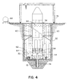
- Each member of the launch vehicle family can also be launched by a universal launch facility in accordance with the present invention, as shown in Figure 4. This is preferred over the canister launcher since a single universal launch facility can launch any size vehicle, including non-axisymmetric vehicles, such as those with strapon rocket motors.
- the universal launch facility utilizes a steel canister 50 that is sized to hold the maximum diameter and length launch vehicle.
- the steel canister 50 is secured in a concrete-lined launch pit 52 and the vehicle is expelled from the canister 50 by a piston 54.
- the piston 54 is caught by an arrestor device 56 upon reaching the end of the canister 50.
- An assembly platform 58 at the top of the piston 54 provides a platform for assembling the launch vehicle.
- the piston 54 is preferably driven by a pressurized cold gas, such as nitrogen or air, although hot gases or steam can also be used.
- a pressurized gas supply system supplies the pressurized gas to the piston 54.
- the pressurized gas supply system includes a series of large diameter steel pipes 60 for storing the gas, a liquid storage tank 62 for supplying the gas, and a butterfly valve 64 at the bottom of each steel pipe 60 to release the gas for launch.
- the pressurized gas drives the piston 54 and the vehicle to a velocity of about 150 fps. When the piston 54 nears the top of the canister 50, it passes vent holes 66 which rapidly bleed pressure from the canister 50.
- the piston 54 then encounters the arrestor device 56, which uses heavy springs and hydraulic or crushable snubbers to stop the piston 54.
- the arrestor device 56 uses heavy springs and hydraulic or crushable snubbers to stop the piston 54.
- the universal launch facility requires no pads on the launch vehicle, thus eliminating considerable cost and complexity compared with a conventional canister launcher.
- the piston 54 and assembly platform 58 also serve as an elevator for minimizing the amount of ground support equipment needed for assembly, servicing and launch.
- the piston 54 and assembly platform 58 are raised and lowered by varying the gas pressure or by means of a hydraulic system.
- the hydraulic system includes a hydraulic reservoir 68, a hydraulic pump 70, a hydraulic line 72 and a hydraulic elevator 74. Assembly of a vehicle is accomplished by raising the piston 54 to the top of the canister 50, assembling the first stage module on the platform 58, then lowering the piston 54 for assembly of successive stages. Mechanical brakes lock the piston 54 in place during the assembly operation. All work is thus performed at ground level, eliminating the need for gantries. Only a single overhead crane 76 is required to lift the components from their transport vehicles and place them at work level.
- the combination of the modular launch vehicle and ground level operations allows the vehicle to be assembled very quickly. This results in low capital investment and low operational costs.
- solid motors have no functioning parts that can be tested prior to launch, other than for electrical continuity, thus eliminating the expense of testing. Therefore, the low-cost launch facility of the present invention when combined with the low-cost launch vehicle of the present invention greatly reduces overall launch costs.
- the present invention represents a significant advance in the field of launch systems.
Landscapes
- Engineering & Computer Science (AREA)
- Remote Sensing (AREA)
- Aviation & Aerospace Engineering (AREA)
- Chemical & Material Sciences (AREA)
- Combustion & Propulsion (AREA)
- Mechanical Engineering (AREA)
- General Engineering & Computer Science (AREA)
- Physics & Mathematics (AREA)
- Astronomy & Astrophysics (AREA)
- General Physics & Mathematics (AREA)
- Testing Of Engines (AREA)
- Automatic Assembly (AREA)
- Filling Or Discharging Of Gas Storage Vessels (AREA)
Claims (8)
- Familie modularer Feststoffträgerraketen, wobei jede Trägerrakete folgendes aufweist:eine untere Stufe aus einem oder mehreren großen modularen Raketentriebwerken (10) für festen Treibstoff, die miteinander gebündelt sind, wobei jedes der großen Raketentriebwerke (10) ein Gewicht von ca. 50.000 kg bis 56.700 kg (110.000 bis 125.000 Pound), einen vakuumspezifischen Impuls von ca. 260 bis 290 Sekunden und eine Wirkungsdauer von ca. 58 bis 90 Sekunden hat; undeine obere Stufe aus einem oder mehreren kleine modularen Raketentriebwerken (12), die miteinander gebündelt sind, wobei jedes der kleinen Raketentriebwerke (12) ein Gewicht von ca. 7.700 kg bis 22.700 kg (17.000 bis 50.000 Pound), einen vakuumspezifischen Impuls von ca. 270 bis 305 Sekunden und eine Wirkungsdauer von ca. 60 bis 130 Sekunden hat.
- Familie von Trägerraketen nach Anspruch 1, bei der jede Trägerrakete des weiteren eine mittlere Stufe aus einem oder mehreren großen modularen Raketentriebwerken (10) für festen Treibstoff, die miteinander gebündelt sind, aufweist, die zwischen der oberen und der unteren Stufe angeordnet ist.
- Familie von Trägerraketen nach Anspruch 1 oder 2, bei der jede Trägerrakete des weiteren eine Zwischenstufe (30) zum Koppeln benachbarter Stufen aufweist, wobei die Zwischenstufe (30) eine Schalenschürze mit Endplatten hat, an denen die Raketentriebwerke befestigt sind, sowie eine linear geformte Sprengladung zum Durchschneiden der Schürze beim Abtrennen der Stufe.
- Familie von Trägerraketen nach einem der vorstehenden Ansprüche, bei der die Durchmesser der großen (10) und kleinen (12) modularen Raketentriebwerke identisch sind und ca. 2,1 m bis 3,1 m (83 bis 120 Zoll) betragen.
- Familie von Trägerraketen nach einem der vorstehenden Ansprüche, bei der die Mitglieder der Familie von Trägerraketen (14, 16, 18, 20, 22, 24, 26) folgende Bündel aufweisen:(a) drei große (10) und drei kleine (12) modulare Raketentriebwerke; oder(b) vier große (10) und vier kleine (12) modulare Raketentriebwerke; oder(c) fünf große (10) und fünf kleine (12) modulare Raketentriebwerke; oder(d) sieben große (10) und sieben kleine (12) modulare Raketentriebwerke.
- Familie von Trägerraketen nach einem der vorstehenden Ansprüche, bei der jede Trägerrakete des weiteren eine Vielzahl Feststoff-Zusatztriebwerken aufweist, die an der ersten Stufe der modularen Raketentriebwerke (10) angeordnet sind.
- Familie von Trägerraketen nach Anspruch 6, bei der jedes Feststoff-Zusatztriebwerk ein großes modulares Raketentriebwerk (10) ist.
- Familie von Trägerraketen nach einem der vorstehenden Ansprüche, bei der jede Trägerrakete des weiteren eine konforme Verkleidung (34) zum Schutz einer in der oberen Stufe untergebrachten Nutzlast aufweist, wobei es die Bündelung der modularen Raketentriebwerke (10, 12) ermöglicht, daß die konforme Verkleidung (34) eine große, feste Nutzlast aufnimmt.
Applications Claiming Priority (2)
| Application Number | Priority Date | Filing Date | Title |
|---|---|---|---|
| US681825 | 1991-04-08 | ||
| US07/681,825 US5217188A (en) | 1991-04-08 | 1991-04-08 | Modular solid-propellant launch vehicle and related launch facility |
Publications (3)
| Publication Number | Publication Date |
|---|---|
| EP0508609A2 EP0508609A2 (de) | 1992-10-14 |
| EP0508609A3 EP0508609A3 (en) | 1993-01-13 |
| EP0508609B1 true EP0508609B1 (de) | 1998-05-20 |
Family
ID=24736992
Family Applications (1)
| Application Number | Title | Priority Date | Filing Date |
|---|---|---|---|
| EP92302182A Expired - Lifetime EP0508609B1 (de) | 1991-04-08 | 1992-03-13 | Modulare Feststoffträgerrakete und Abschusssystem |
Country Status (4)
| Country | Link |
|---|---|
| US (1) | US5217188A (de) |
| EP (1) | EP0508609B1 (de) |
| JP (1) | JP2779287B2 (de) |
| DE (1) | DE69225526T2 (de) |
Cited By (2)
| Publication number | Priority date | Publication date | Assignee | Title |
|---|---|---|---|---|
| RU2595092C1 (ru) * | 2015-07-28 | 2016-08-20 | Общество с ограниченной ответственностью "КосмоКурс" (ООО "КосмоКурс") | Способ выведения на орбиту полезной нагрузки ракетой-носителем |
| WO2017018903A1 (ru) * | 2015-07-28 | 2017-02-02 | Общество С Ограниченной Ответственностью "Космокурс" Ооо "Космокурс" | Способ выведения на орбиту полезной нагрузки ракетой-носителем |
Families Citing this family (45)
| Publication number | Priority date | Publication date | Assignee | Title |
|---|---|---|---|---|
| US5344104A (en) * | 1992-09-21 | 1994-09-06 | General Electric Co. | Low cost, selectable configuration spacecraft |
| IL104925A (en) * | 1993-03-02 | 1997-08-14 | Raviv Dov | Launching vehicle |
| US5350137A (en) * | 1993-05-19 | 1994-09-27 | General Dynamics Corporation Space Systems Division | Multiple application paraboloid spacecraft structure |
| US5566909A (en) * | 1993-09-08 | 1996-10-22 | Hughes Aircraft Company | System and method for deploying multiple probes |
| US5850989A (en) * | 1994-02-18 | 1998-12-22 | Lockheed Martin Corporation | Method and system for rapidly assembling a launch vehicle |
| US5743492A (en) * | 1994-02-18 | 1998-04-28 | Lockheed Martin Corporation | Payload housing and assembly joint for a launch vehicle |
| US5529264A (en) * | 1994-02-18 | 1996-06-25 | Lockheed Missiles & Space Company, Inc. | Launch vehicle system |
| US5816539A (en) * | 1994-02-18 | 1998-10-06 | Lockheed Martin Corporation | Orbital assist module and interstage |
| EP0763468B1 (de) * | 1995-09-18 | 2002-03-20 | Microcosm, Inc. | Wirtschaftliche Trägerrakete |
| US5927653A (en) * | 1996-04-17 | 1999-07-27 | Kistler Aerospace Corporation | Two-stage reusable earth-to-orbit aerospace vehicle and transport system |
| US5924648A (en) * | 1997-10-03 | 1999-07-20 | Lockheed Martin Corporation | System for upending/reclining launch vehicles |
| US6036144A (en) * | 1997-10-03 | 2000-03-14 | Lockheed Martin Corporation | Mass producible launch system |
| US6059234A (en) * | 1998-02-25 | 2000-05-09 | Kistler Aerospace Corporation | Payload module |
| US6158693A (en) * | 1998-02-25 | 2000-12-12 | Kistler Aerospace Corporation | Recoverable booster stage and recovery method |
| US6186039B1 (en) | 1998-02-25 | 2001-02-13 | Kistler Aerospace Corporation | Spacecraft launch system and method |
| US6612522B1 (en) * | 1998-03-17 | 2003-09-02 | Starcraft Boosters, Inc. | Flyback booster with removable rocket propulsion module |
| US6176451B1 (en) | 1998-09-21 | 2001-01-23 | Lockheed Martin Corporation | Utilizing high altitude long endurance unmanned airborne vehicle technology for airborne space lift range support |
| RU2161108C1 (ru) | 2000-02-07 | 2000-12-27 | Государственный космический научно-производственный центр им. М.В. Хруничева | Способ выведения на орбиту полезной нагрузки многофункциональной ракетой-носителем комбинированной схемы с маршевыми жидкостными ракетными двигательными установками (жрду), многофункциональная ракета-носитель комбинированной схемы с маршевыми жрду и способ ее отработки |
| DE10052422B4 (de) | 2000-10-23 | 2004-03-04 | Astrium Gmbh | Modulares Raketentriebwerk |
| GB0107552D0 (en) | 2001-03-27 | 2005-01-05 | Matra Bae Dynamics Uk Ltd | Improvements in and relating to the launching of missiles |
| RU2179941C1 (ru) * | 2001-07-12 | 2002-02-27 | ЗАО "Пусковые услуги" | Космический ракетный комплекс и способ обеспечения услуг по запуску космических аппаратов с использованием космического ракетного комплекса |
| RU2215673C2 (ru) * | 2001-10-03 | 2003-11-10 | Шуликов Константин Владимирович | Авиационно-космический стартовый комплекс "марс" |
| US6789454B2 (en) * | 2002-10-16 | 2004-09-14 | Rescue Academy Inc. | Gun barrel for launching large projectiles |
| US7182014B2 (en) * | 2002-10-16 | 2007-02-27 | Rescue Academy Inc. | Gun barrel for launching projectiles |
| US7254936B1 (en) * | 2004-04-26 | 2007-08-14 | Knight Andrew F | Simple solid propellant rocket engine and super-staged rocket |
| US7879031B2 (en) * | 2005-09-27 | 2011-02-01 | Covidien Ag | Cooled RF ablation needle |
| US7451680B1 (en) * | 2006-10-20 | 2008-11-18 | The United States Of America As Represented By The Secretary Of The Navy | Submarine steam generator missile ejection system |
| US7992491B1 (en) | 2008-04-25 | 2011-08-09 | Forest Concepts, LLC | Engineered top infeed hopper system |
| RU2414391C1 (ru) * | 2009-06-22 | 2011-03-20 | Государственное Образовательное Учреждение Высшего Профессионального Образования "Омский Государственный Технический Университет" | Способ спуска отделяющейся части ступени ракеты космического назначения и устройство для его осуществления |
| RU2441814C2 (ru) * | 2009-12-24 | 2012-02-10 | Федеральное государственное унитарное предприятие "Государственный космический научно-производственный центр имени М.В. Хруничева" | Способ компоновки многоразовых ракет космического назначения |
| CA2719190C (en) | 2010-03-10 | 2014-04-01 | 1540049 Alberta Ltd. | Method and apparatus for assembling a workpiece |
| US9003965B2 (en) | 2011-01-26 | 2015-04-14 | Forest Concepts, LLC | Method of producing switchgrass whole stalk bales at high densities optimized for transport on semi-trailer trucks to biorefineries |
| US8359974B2 (en) | 2011-01-26 | 2013-01-29 | Forest Concepts, LLC | Method of baling switchgrass or miscanthus at optimum highway transport densities |
| US9809143B2 (en) | 2011-06-23 | 2017-11-07 | Forest Concepts, LLC | Cargo of rectangular bales of switchgrass or miscanthus stalks optimized for high density transport on semi-trailer trucks to biorefineries |
| US8998131B1 (en) * | 2013-10-17 | 2015-04-07 | The Boeing Company | Differential throttling control enhancement |
| US9845166B2 (en) * | 2014-06-04 | 2017-12-19 | Ventions, Llc | Pneumatic cubesat payload deployment system utilizing launch vehicle tank pressure |
| RU2708123C2 (ru) * | 2016-09-20 | 2019-12-04 | Харис Нуриахметович Мухаметшин | Устройство для запуска космических ракет |
| US10974853B1 (en) | 2018-11-13 | 2021-04-13 | United Launch Alliance, L.L.C. | White room modular system for launch vehicles |
| CN110594038B (zh) * | 2019-08-20 | 2021-11-09 | 西安航天动力技术研究所 | 一种多次脉冲激励装置 |
| RU2750343C1 (ru) * | 2020-02-28 | 2021-06-28 | Публичное акционерное общество "Ракетно-космическая корпорация "Энергия" имени С.П. Королева" | Компоновка многоступенчатой модульной ракеты-носителя |
| MA61702B1 (fr) * | 2020-12-15 | 2025-05-30 | Agnikul Cosmos Private Limited | Système satellite et véhicule de lancement combiné |
| CN112966340B (zh) * | 2021-01-19 | 2023-12-29 | 中国人民解放军63921部队 | 一种固体捆绑运载火箭运载能力的小偏差快速修正方法 |
| US11518547B1 (en) * | 2021-06-18 | 2022-12-06 | AT Space Pty Ltd | Booster system for launch vehicle |
| CN118265654A (zh) | 2021-09-02 | 2024-06-28 | 阿尼库尔宇宙私人有限公司 | 运载火箭系统的模块化构造 |
| CN116378857A (zh) * | 2023-04-07 | 2023-07-04 | 武汉高德红外股份有限公司 | 火箭发动机模拟试验装置及方法 |
Family Cites Families (19)
| Publication number | Priority date | Publication date | Assignee | Title |
|---|---|---|---|---|
| US2515048A (en) * | 1943-04-02 | 1950-07-11 | Us Navy | Multiple rocket motor |
| US3093964A (en) * | 1960-12-14 | 1963-06-18 | United Aircraft Corp | Two-stage rocket |
| US3202381A (en) * | 1961-11-08 | 1965-08-24 | Hans F Wuenscher | Recoverable rocket vehicle |
| US3267809A (en) * | 1962-04-25 | 1966-08-23 | Sikora Jozef | Apparatus for launching satellitecarrying rockets |
| US3284888A (en) * | 1963-05-09 | 1966-11-15 | Edward J Donnelly | Method and apparatus for assembling and erecting a rocket or missile |
| GB1114414A (en) * | 1964-06-18 | 1968-05-22 | British Aircraft Corp Ltd | Improvements in space vehicles |
| US3286629A (en) * | 1964-10-07 | 1966-11-22 | Jay H Laue | Multi-mission module |
| US3702688A (en) * | 1971-01-04 | 1972-11-14 | Nasa | Space shuttle vehicle and system |
| US4344592A (en) * | 1977-11-10 | 1982-08-17 | Spiridon Constantinescu | Launching tower for heavy rockets |
| US4451017A (en) * | 1982-09-30 | 1984-05-29 | The United States Of America As Represented By The Administrator, National Aeronautics And Space Administration | Three stage rocket vehicle with parallel staging |
| US5217187A (en) * | 1983-11-07 | 1993-06-08 | Criswell David R | Multi-use launch system |
| US4834324A (en) * | 1983-11-07 | 1989-05-30 | Criswell David R | Multiconfiguration reusable space transportation system |
| US4625619A (en) * | 1984-07-02 | 1986-12-02 | The United States Of America As Represented By The Secretary Of The Navy | Device for separation and launch of a body with linear and rotational velocity |
| US4604938A (en) * | 1984-08-02 | 1986-08-12 | The United States Of America As Represented By The Secretary Of The Navy | Arresting and recovery system for test missiles |
| US4671163A (en) * | 1985-07-15 | 1987-06-09 | Westinghouse Electric Corp. | Method of launching a missile using secondary combustion |
| US5172875A (en) * | 1988-03-30 | 1992-12-22 | Israel Fried | Space launcher and method for launching objects into space |
| US4956971A (en) * | 1988-08-03 | 1990-09-18 | Morton Thiokol, Inc. | Solid propellant canister loaded multiple pulsed or staged rocket motor |
| US4932607A (en) * | 1988-08-19 | 1990-06-12 | Martin Marietta Corporation | Universal erection and processing system for launching a space vehicle |
| JPH02296600A (ja) * | 1989-05-09 | 1990-12-07 | Hazama Gumi Ltd | 飛翔体発射施設 |
-
1991
- 1991-04-08 US US07/681,825 patent/US5217188A/en not_active Expired - Fee Related
-
1992
- 1992-03-13 DE DE69225526T patent/DE69225526T2/de not_active Expired - Fee Related
- 1992-03-13 EP EP92302182A patent/EP0508609B1/de not_active Expired - Lifetime
- 1992-03-31 JP JP4077757A patent/JP2779287B2/ja not_active Expired - Fee Related
Cited By (2)
| Publication number | Priority date | Publication date | Assignee | Title |
|---|---|---|---|---|
| RU2595092C1 (ru) * | 2015-07-28 | 2016-08-20 | Общество с ограниченной ответственностью "КосмоКурс" (ООО "КосмоКурс") | Способ выведения на орбиту полезной нагрузки ракетой-носителем |
| WO2017018903A1 (ru) * | 2015-07-28 | 2017-02-02 | Общество С Ограниченной Ответственностью "Космокурс" Ооо "Космокурс" | Способ выведения на орбиту полезной нагрузки ракетой-носителем |
Also Published As
| Publication number | Publication date |
|---|---|
| EP0508609A3 (en) | 1993-01-13 |
| JP2779287B2 (ja) | 1998-07-23 |
| DE69225526D1 (de) | 1998-06-25 |
| DE69225526T2 (de) | 1998-11-26 |
| US5217188A (en) | 1993-06-08 |
| EP0508609A2 (de) | 1992-10-14 |
| JPH05105200A (ja) | 1993-04-27 |
Similar Documents
| Publication | Publication Date | Title |
|---|---|---|
| EP0508609B1 (de) | Modulare Feststoffträgerrakete und Abschusssystem | |
| US5529264A (en) | Launch vehicle system | |
| US5667167A (en) | Methods and apparatus for reusable launch platform and reusable spacecraft | |
| US5816539A (en) | Orbital assist module and interstage | |
| EP3333086B1 (de) | Systeme und verfahren zum aussetzen von raumfahrzeugen | |
| AU612549B2 (en) | Rocket-powered, air-deployed, lift-assisted booster vehicle for orbital, supraorbital and suborbital flight | |
| US4964340A (en) | Overlapping stage burn for multistage launch vehicles | |
| US8047472B1 (en) | Ram booster | |
| US6612522B1 (en) | Flyback booster with removable rocket propulsion module | |
| US6138951A (en) | Spacecraft dispensing system | |
| US9475591B2 (en) | Space launch apparatus | |
| US6036144A (en) | Mass producible launch system | |
| US20170036782A1 (en) | Launch apparatus | |
| US20180290767A1 (en) | Satellite Launcher And Method For Putting Satellites Into Orbit Using Said Satellite Launcher | |
| RU2129508C1 (ru) | Авиационный пусковой комплекс | |
| US20250026498A1 (en) | Modular configuration of launch vehicle system | |
| Gallucci et al. | Vega Space System | |
| Gamal et al. | Development of a suborbital inexpensive rocket for affordable space access | |
| Johnson, MS et al. | Architectural Study of Crew Launch Escape Systems with Ascent Assist Capability | |
| Aerospace | TITAN IIIE/CENTAUR D-IT SYSTEMS SUMMARY | |
| Vehko et al. | A “Zero Stage” for the Saturn IB Launch Vehicle | |
| Mochizuki et al. | Status report of the HI and H-II vehicles | |
| Chase | Development status of the Inertial Upper Stage solid motors | |
| Frew et al. | Titan Launch Vehicle Program Overview | |
| Hampsten | An air launched, highly responsive military transatmospheric vehicle (TAV), based on existing aerospace systems |
Legal Events
| Date | Code | Title | Description |
|---|---|---|---|
| PUAI | Public reference made under article 153(3) epc to a published international application that has entered the european phase |
Free format text: ORIGINAL CODE: 0009012 |
|
| AK | Designated contracting states |
Kind code of ref document: A2 Designated state(s): DE FR GB |
|
| PUAL | Search report despatched |
Free format text: ORIGINAL CODE: 0009013 |
|
| AK | Designated contracting states |
Kind code of ref document: A3 Designated state(s): DE FR GB |
|
| 17P | Request for examination filed |
Effective date: 19930602 |
|
| 17Q | First examination report despatched |
Effective date: 19940728 |
|
| APAB | Appeal dossier modified |
Free format text: ORIGINAL CODE: EPIDOS NOAPE |
|
| APBJ | Interlocutory revision of appeal recorded |
Free format text: ORIGINAL CODE: EPIDOS IRAPE |
|
| GRAG | Despatch of communication of intention to grant |
Free format text: ORIGINAL CODE: EPIDOS AGRA |
|
| GRAG | Despatch of communication of intention to grant |
Free format text: ORIGINAL CODE: EPIDOS AGRA |
|
| GRAH | Despatch of communication of intention to grant a patent |
Free format text: ORIGINAL CODE: EPIDOS IGRA |
|
| GRAH | Despatch of communication of intention to grant a patent |
Free format text: ORIGINAL CODE: EPIDOS IGRA |
|
| GRAA | (expected) grant |
Free format text: ORIGINAL CODE: 0009210 |
|
| AK | Designated contracting states |
Kind code of ref document: B1 Designated state(s): DE FR GB |
|
| REF | Corresponds to: |
Ref document number: 69225526 Country of ref document: DE Date of ref document: 19980625 |
|
| ET | Fr: translation filed | ||
| PLBQ | Unpublished change to opponent data |
Free format text: ORIGINAL CODE: EPIDOS OPPO |
|
| PLBI | Opposition filed |
Free format text: ORIGINAL CODE: 0009260 |
|
| PLBF | Reply of patent proprietor to notice(s) of opposition |
Free format text: ORIGINAL CODE: EPIDOS OBSO |
|
| 26 | Opposition filed |
Opponent name: CENTRE NATIONAL D'ETUDE SPATIALES Effective date: 19990216 |
|
| PLBF | Reply of patent proprietor to notice(s) of opposition |
Free format text: ORIGINAL CODE: EPIDOS OBSO |
|
| PLBO | Opposition rejected |
Free format text: ORIGINAL CODE: EPIDOS REJO |
|
| APAC | Appeal dossier modified |
Free format text: ORIGINAL CODE: EPIDOS NOAPO |
|
| APAE | Appeal reference modified |
Free format text: ORIGINAL CODE: EPIDOS REFNO |
|
| APAC | Appeal dossier modified |
Free format text: ORIGINAL CODE: EPIDOS NOAPO |
|
| REG | Reference to a national code |
Ref country code: GB Ref legal event code: IF02 |
|
| PLBQ | Unpublished change to opponent data |
Free format text: ORIGINAL CODE: EPIDOS OPPO |
|
| PLAB | Opposition data, opponent's data or that of the opponent's representative modified |
Free format text: ORIGINAL CODE: 0009299OPPO |
|
| R26 | Opposition filed (corrected) |
Opponent name: CENTRE NATIONAL D'ETUDE SPATIALES Effective date: 19990216 |
|
| PGFP | Annual fee paid to national office [announced via postgrant information from national office to epo] |
Ref country code: GB Payment date: 20030204 Year of fee payment: 12 |
|
| PGFP | Annual fee paid to national office [announced via postgrant information from national office to epo] |
Ref country code: FR Payment date: 20030303 Year of fee payment: 12 |
|
| PGFP | Annual fee paid to national office [announced via postgrant information from national office to epo] |
Ref country code: DE Payment date: 20030331 Year of fee payment: 12 |
|
| REG | Reference to a national code |
Ref country code: GB Ref legal event code: 732E |
|
| RAP2 | Party data changed (patent owner data changed or rights of a patent transferred) |
Owner name: NORTHROP GRUMMAN CORPORATION |
|
| PG25 | Lapsed in a contracting state [announced via postgrant information from national office to epo] |
Ref country code: GB Free format text: LAPSE BECAUSE OF NON-PAYMENT OF DUE FEES Effective date: 20040313 |
|
| PG25 | Lapsed in a contracting state [announced via postgrant information from national office to epo] |
Ref country code: DE Free format text: LAPSE BECAUSE OF NON-PAYMENT OF DUE FEES Effective date: 20041001 |
|
| GBPC | Gb: european patent ceased through non-payment of renewal fee |
Effective date: 20040313 |
|
| PG25 | Lapsed in a contracting state [announced via postgrant information from national office to epo] |
Ref country code: FR Free format text: LAPSE BECAUSE OF NON-PAYMENT OF DUE FEES Effective date: 20041130 |
|
| REG | Reference to a national code |
Ref country code: FR Ref legal event code: ST |
|
| APBU | Appeal procedure closed |
Free format text: ORIGINAL CODE: EPIDOSNNOA9O |
|
| REG | Reference to a national code |
Ref country code: FR Ref legal event code: TP Ref country code: FR Ref legal event code: CD |
|
| APAH | Appeal reference modified |
Free format text: ORIGINAL CODE: EPIDOSCREFNO |
|
| PLAB | Opposition data, opponent's data or that of the opponent's representative modified |
Free format text: ORIGINAL CODE: 0009299OPPO |
|
| PLBN | Opposition rejected |
Free format text: ORIGINAL CODE: 0009273 |
|
| STAA | Information on the status of an ep patent application or granted ep patent |
Free format text: STATUS: OPPOSITION REJECTED |
|
| R26 | Opposition filed (corrected) |
Opponent name: CENTRE NATIONAL D'ETUDE SPATIALES Effective date: 19990216 |
|
| 27O | Opposition rejected |
Effective date: 20041124 |