EP0508384B1 - Recording/reproducing apparatus - Google Patents
Recording/reproducing apparatus Download PDFInfo
- Publication number
- EP0508384B1 EP0508384B1 EP92106014A EP92106014A EP0508384B1 EP 0508384 B1 EP0508384 B1 EP 0508384B1 EP 92106014 A EP92106014 A EP 92106014A EP 92106014 A EP92106014 A EP 92106014A EP 0508384 B1 EP0508384 B1 EP 0508384B1
- Authority
- EP
- European Patent Office
- Prior art keywords
- frame
- recording
- support means
- reproducing apparatus
- tape
- Prior art date
- Legal status (The legal status is an assumption and is not a legal conclusion. Google has not performed a legal analysis and makes no representation as to the accuracy of the status listed.)
- Expired - Lifetime
Links
Images


Classifications
-
- G—PHYSICS
- G11—INFORMATION STORAGE
- G11B—INFORMATION STORAGE BASED ON RELATIVE MOVEMENT BETWEEN RECORD CARRIER AND TRANSDUCER
- G11B15/00—Driving, starting or stopping record carriers of filamentary or web form; Driving both such record carriers and heads; Guiding such record carriers or containers therefor; Control thereof; Control of operating function
- G11B15/60—Guiding record carrier
- G11B15/66—Threading; Loading; Automatic self-loading
- G11B15/665—Threading; Loading; Automatic self-loading by extracting loop of record carrier from container
- G11B15/6653—Threading; Loading; Automatic self-loading by extracting loop of record carrier from container to pull the record carrier against drum
-
- G—PHYSICS
- G11—INFORMATION STORAGE
- G11B—INFORMATION STORAGE BASED ON RELATIVE MOVEMENT BETWEEN RECORD CARRIER AND TRANSDUCER
- G11B15/00—Driving, starting or stopping record carriers of filamentary or web form; Driving both such record carriers and heads; Guiding such record carriers or containers therefor; Control thereof; Control of operating function
- G11B15/60—Guiding record carrier
- G11B15/66—Threading; Loading; Automatic self-loading
- G11B15/665—Threading; Loading; Automatic self-loading by extracting loop of record carrier from container
-
- G—PHYSICS
- G11—INFORMATION STORAGE
- G11B—INFORMATION STORAGE BASED ON RELATIVE MOVEMENT BETWEEN RECORD CARRIER AND TRANSDUCER
- G11B15/00—Driving, starting or stopping record carriers of filamentary or web form; Driving both such record carriers and heads; Guiding such record carriers or containers therefor; Control thereof; Control of operating function
- G11B15/60—Guiding record carrier
- G11B15/61—Guiding record carrier on drum, e.g. drum containing rotating heads
- G11B15/615—Guiding record carrier on drum, e.g. drum containing rotating heads inside container
-
- G—PHYSICS
- G11—INFORMATION STORAGE
- G11B—INFORMATION STORAGE BASED ON RELATIVE MOVEMENT BETWEEN RECORD CARRIER AND TRANSDUCER
- G11B15/00—Driving, starting or stopping record carriers of filamentary or web form; Driving both such record carriers and heads; Guiding such record carriers or containers therefor; Control thereof; Control of operating function
- G11B15/675—Guiding containers, e.g. loading, ejecting cassettes
- G11B15/6751—Guiding containers, e.g. loading, ejecting cassettes with movement of the cassette parallel to its main side, i.e. front loading
Definitions
- the present invention relates to a recording/reproducing apparatus, such as a video cassette recorder (hereinafter abbreviated as VCR) or a digital audio tape recorder (DAT) for recording and reproducing video signals and/or audio signals of a tape cassette which is to be loaded into the recording/reproducing apparatus.
- VCR video cassette recorder
- DAT digital audio tape recorder
- the recording/reproducing apparatus records and/or reproduces such signals by drawing a part of tape from the tape cassette into an operating position, and moving it in a predetermined tape path so as to be wound around a tape guide drum.
- VCR VCR
- portable VCR incorporated in a camera unit in one body
- a user is intensively expecting that such VCR is configured small-sized and light-weighted. Therefore, it is the very important factor to develop a small-sized and light-weight VCR in order to spread the portable VCR.
- VCR VCR
- some portable VCR are designed to have a tape guide drum to be inserted into a front opening of the tape cassette when the tape is wound around the tape guide drum. And further, some portable VCR are designed to slide an outer case of the VCR toward an inner space where the path-forming means has passed for winding around the tape guide drum.
- Example of such a conventional VCR as a recording/reproducing apparatus is shown in the Japanese published examined patent application No. sho 62-180551 (Tokkou Sho 62-180551) which was filed by the same assignee.
- the conventional recording/reproducing apparatus when the stretched tape in the tape cassette is wound around the tape guide drum to form a predetermined tape path, the loaded tape cassette and the tape guide drum provided in the apparatus are moved to close each other, and the outer case of the apparatus is slid to shrink. Therefore, the conventional recording/reproducing apparatus is disadvantageous in that a complicated mechanisms for loading operation of the tape cassette and for sliding operation of the outer case must be provided in the apparatus. As a result, it has been so difficult to configure the conventional recording/reproducing apparatus in a small-size and light-weight.
- EP-A-0 449 658 discloses a recording/reproducing apparatus comprising a first support means in form of a chassis for supporting a tape cassette and a second support means in form of a chassis for supporting a rotary head drum.
- the cited document neither teaches nor suggests a means for moving the first chassis and the second chassis together. That is, in the cited document, the second chassis in the form of a plate is supported on the first chassis and is slidable into and out of the first chassis. Furthermore, in this cited document, the rotary head drum on the second chassis is inserted into the tape cassette, and a head drum base engages and presses the two reel support chassis.
- the distance between the two reel supports is changed by the movement of the rotary head drum according to the contours of the reel support chassis. Therefore, in this cited document, high working precision is required in manufacturing the two reel support chassis. Moreover, basically, the only requirement for the reel supports is to rotate inherently; however, the reel supports of the cited document are required to move. Therefore a mechanism for driving the reel supports inevitably must be complicated; thereby the recording/reproducing apparatus cannot be achieved with small size, light weight and low costs. Furthermore, since the reels move in the tape cassette, it is necessary that the tape cassette has a complicated construction. And the length of the tape is not increased because of the above-mentioned construction of the recording/reproducing apparatus.
- the present invention discloses a means for moving the first support means and the second support means together in a first direction after the first support means has been moved in the first direction.
- it is thereby possible to effectively use a rear space of a tape guide drum arranged for the movement of loading posts. That is, the rear space receives the second support means after the loading posts have passed through the rear space by the operation of the above-mentioned means. Therefore the recording/reproducing apparatus of the present invention can be constructed in a minimum space to receive the whole mechanism for forming the tape path.
- FIG.1 to FIG.3 are plan views showing main parts of a loading mechanism of a recording/reproducing apparatus of a first embodiment in accordance with the present invention.
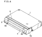
- FIG.4 is a plan side perspective view showing a known tape cassette to be loaded in the recording/reproducing apparatus.
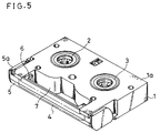
- FIG.5 is a rear side perspective view showing the tape cassette of FIG.4.
- FIG.6 is a cross-sectional side view showing the tape cassette of FIG.4.
- FIG.7 is a plan view showing main parts of a tape loading mechanism of the recording/reproducing apparatus of the first embodiment in accordance with the present invention.
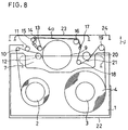
- FIG.8 is a plan view showing the main parts of the tape loading mechanism on a finished winding operation.
- FIGs.9(a), 9(b),and 9(c) show movements of the tape loading mechanism in a loading operation of the first embodiment.
- FIG.10 is a plan view showing main parts of a recording/reproducing apparatus of a second embodiment in accordance with the present invention.
- FIG.11 to FIG.14 are cross-sectional side views showing a recording/reproducing apparatus of a third embodiment in accordance with the present invention.
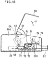
- FIG.15 and FIG.16 are side views of the recording/reproducing apparatus of FIG.11 for showing a turning block mechanism.
- FIG.17 is an exploded perspective view of the turning block mechanism of FIG.15.
- FIGs. 1 to 9 a first embodiment of a recording/reproducing apparatus, such as a portable VCR, etc., of the present invention is described referring to the accompanying drawings of FIGs. 1 to 9.
- FIGs.1 to 3 are plan views showing main parts of a loading mechanism of the recording/reproducing apparatus in accordance with the present invention.
- FIG.4 is a plan side perspective view showing a tape cassette which is to be loaded to the recording/reproducing apparatus of the present invention.
- FIG.5 is a rear side perspective view showing the tape cassette of FIG.4.
- FIG.6 is a cross-sectional side view showing the tape cassette of FIG.4.
- FIGs.7 and 8 are plan views showing main tape loading mechanism in the cassette loading operation of the recording/reproducing apparatus.
- FIG.9 shows the movements of the tape loading mechanism in the cassette loading operation of the first embodiment in accordance with the present invention.
- a tape 4 which is wound around a supply reel 2 as well as a take-up reel in the tape cassette 1, is stretched there between through a pair of cassette posts 8a, 8b in the front of the tape cassette 1.
- the stretched tape 4 and the cassette posts 8a, 8b are shown by the alternate long and short dash lines in FIG.4.
- the part of tape 4 disposed in the front part of the tape cassette 1 is disposed between a lid 5 and a back lid 6, which is situated near the back face of the stretched tape 4 between the cassette posts 8a and 8b, when the tape cassette 1 is not loaded in the recording/reproducing apparatus.
- an opening 7 of the tape cassette 1 is formed on a front side of the rear face 1a.
- the opening 7 of the tape cassette 1 is arranged in a manner to provide therein various loading posts for drawing the stretched tape 4 from the tape cassette 1 to the inner part of the recording/reproducing apparatus when the tape cassette 1 is loaded to the recording/reproducing apparatus.
- a known lid open mechanism (not shown) for opening the lid 5 and the back lid 6 of the tape cassette 1 contacts with a side face 5a of the lid 5, so as to open the lid 5 and the back lid 6 as shown in FIG.6.
- the back lid 6 In a non-loaded state where the tape cassette 1 is taken out of the recording/reproducing apparatus, the back lid 6 is arranged at rear side of the lid 5 with the stretched tape 4 in between.
- the back lid 6 is supported by a support plate 5b (FIG.6) of the lid 5, by rotatably jounalling an end portion 6a of the back lid 6 on the support plate 5b.
- a guide pin 6b of the back lid 6 is engaged with an arc-shaped guide groove 7b which are formed on both side faces 7a of the tape cassette 1, and is guided rotatably by the arc-shaped guide grooves 7b.
- the lid 5 and the back lid 6 are rotated by the lid open mechanism along a predetermined locus as shown by the alternate long and short dash line in FIG.6 without contact to the tape 4 stretched in front of the tape cassette 1.
- the lid 5 and the back lid 6 are entirely opened by the lid open mechanism, the lid 5 and the back lid 6 are rotated to expose the tape 4 stretched between the cassette posts 8a and 8b. That is the lid 5 and the back lid 6 are moved for distances longer than the width of the tape 4. Therefore, a known tape guide drum 9 in the recording/reproducing apparatus can be relatively inserted into the opening 7 of the tape cassette 1 when the tape cassette is loaded to the recording/reproducing apparatus.
- FIG.7 is the diagrammatic plan view showing an arrangement of main parts of the tape loading mechanism in a first step of a cassette loading operation.
- FIG.8 is the diagrammatic plan view showing a tape path established by the main parts of the tape loading mechanism in the end step of the cassette loading operation.
- the tape 4 of the tape cassette 1 which has been described in the foregoing explanation with reference to FIGs.4 to 6, is stretched in front of the tape cassette 1 in the recording/reproducing apparatus when the tape cassette 1 has just been put on a first frame 22 in a first step of the cassette loading operation.
- the tape guide drum 9 having known rotary heads (not shown) is located inside the recording/reproducing apparatus when the tape cassette 1 is just put on the first frame 22 at a position shown in FIG.7.
- various loading posts 10, 12, 13, 14, 15, 16, 17, 19 for forming a tape path and a capstan 21 are moved into the opening 7 of the tape cassette 1 when the tape cassette 1 is just put to the recording/reproducing apparatus.
- the other loading posts 11, 18, a pinch roller 20 and the tape guide drum 9 are arranged outside the opening 7, facing against the stretched tape 4.
- the recording/reproducing apparatus of the first embodiment comprises the first frame 22 for supporting the tape cassette 1 and the like, a second frame 23 providing the tape guide drum 9, and the third frame 24 supporting the first frame 22 and the second frame 23.
- the innermost end of the first frame 22 and the innermost end of the third frame 24 are positioned to have a predetermined interval A as shown in FIG.7.
- the necessary mechanism for loading the tape cassette 1 is arranged in a space which is between the innermost faces of the first frame 22 and the third frame 24.
- the loading posts 10, 11, 12, 18, 19 and the pinch roller 20 start to move toward the predetermined position shown by the alternate long and short dash lines in FIG.7.
- the loading posts 10, 11, 12, 18, 19 and the pinch roller 20 are slid in directions shown by arrows B, C, D, E, F, G, respectively.
- the first frame 22 starts to move in a direction shown by an arrow J.
- the tape cassette 1 approaches the tape guide drum 9.
- the tape 4 in the tape cassette 1 is wound around the tape guide drum 9 by motions of the loading posts 13, 14, 15, 16, 17 in a direction shown by an arrow K.
- a predetermined tape path, where the tape 4 is passed around the loading posts and the tape guide drum 9, is established in the recording/reproducing apparatus.
- FIG.8 shows the established tape path 4a for the recording or reproducing in the first embodiment.
- FIGs.9(a), 9(b) and 9(c) show three stages in the above-mentioned cassette loading operation of the first embodiment in accordance with the present invention.
- FIG.9(a) shows the first stage of the cassette loading operation
- FIG.9(b) shows the intermediate stage of the cassette loading operation when a tape loading operation is finished
- FIG.9(c) shows the end stage of the cassette loading operation.
- the first frame 22 holding the tape cassette 1 and the second frame 23 providing the tape guide drum 9 have been already slid for an interval I from the intermediate stage shown in FIG.9(b), when the tape cassette 1 becomes loaded completely into the recording/reproducing apparatus (FIG.9(c)). Accordingly, when the first frame 22 which holds the tape cassette 1 is slid for the interval H+I, the cassette loading operation of the recording/reproducing apparatus has been finished. Since the advancing motion of the interval I is provided, total depth X of the apparatus box can be decreased in comparison with the conventional apparatus. As a result, the compact recording/reproducing apparatus can be obtained.
- a loading operation will be described hereinunder with a concrete example shown in FIG.1 to FIG.3 with regard to the above-mentioned recording/reproducing apparatus of the first embodiment. Since a driving mechanism for sliding the above-mentioned loading posts 10, 12, 18, 19 and the pinch roller 20 is operated by the known prior art, descriptions on the parts of loading ring means, the driving mechanism for sliding the loading posts 10, 12, 18, 19 and so on are omitted from the following description.
- FIG.1 is a plan view showing main parts of a cassete loading mechanism in the recording/reproducing apparatus.
- a capstan 21 for driving the tape 4 from the supply reel 2 to the take-up reel 3 is put on the first frame 22.
- a supply reel stand 25 and a take-up reel stand 26 are provided on the first frame 22.
- a capstan motor 21a which is configured integral with the capstan 21, is provided under the first frame 22.
- the capstan 21 is rotated by the capstan motor 21a in both directions, that is in a clockwise and a counterclockwise in FIG.1.
- a transmission mechanism for transmitting the turning force to the supply reel stand 25 and the take-up reel stand 26 from the captain motor 21a is provided under the first frame 2.
- the supply reel stand 25 and the take-up reel stand 26 can be rotated in a desired direction by changing the rotary direction of the capstan 21.
- the rotary direction of the supply reel stand 25 or the take-up reel stand 26 is decided by using a known art, e.g. a driving gear system (not shown) whereof the position is changed by friction thereof after transmission of the turning force of the capstan motor 21a to the operation gear through a belt (not shown). Since the transmission mechanism has been known and widely used, an explanation for the transmission mechanism is omitted from the following description.
- the first frame 22 comprises a known cassette guide mechanism (not shown) for guiding the tape cassette 1 to be loaded into the recording/reproducing apparatus. Since the cassette guide mechanism is known and widely, an explanation for the cassette guide mechanism is omitted here.
- the first frame 22 having the cassette guide mechanism for guiding the tape cassette 1 to the first frame 22 is supported slidably on the third frame 24.
- Two guide grooves 22a, 22b of the first frame 22 are engaged with two guide pins 27, 27 on the third frame 24, respectively. Therefore, a sliding direction and a sliding interval of the first frame 22 are defined by the engagement between the guide grooves 22a, 22b, and guide pins 27, 28.
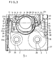
- the above-mentioned tape guide drum 9, an upper loading ring 29 and a lower loading ring 30 shown in FIG.3, and a stationary loading post 11 for forming the tape path are provided as shown in FIG.1.
- the above-mentioned loading posts 13, 14, 15, 16, 17 for forming the tape path are provided on the loading rings 29, 30.
- the loading posts 13, 14, 15 are provided on a first carrier 31 which is mechanically connected to the upper loading ring 29 so as to rotate on a predetermined way.
- the loading posts 16, 17 are provided to a second carrier 32 which is mechanically connected to the lower loading ring 30 so as to rotate on a predetermined way. Since the loading rings 29, 30 are meshed with a second gear 22c of the first frame 22 through two double gears 33, 34 which are pivotably held on the second frame 23, the loading rings 29, 30 are rotated by moving relatively between the first frame 22 and the second frame 23.
- the second frame 23 is slidably supported on the third frame 24 similarly to the first frame 22.
- Two guide grooves 23a, 23b of the second frame 23 are engaged with two guide pins 35, 36 on the third frame 24, respectively. Therefore, a sliding direction and a sliding interval of the second frame 23 are decided by the engagement between the guide grooves 23a, 23b and the guide pins 35, 36.
- the sliding direction of the second frame 23 is selected in the same direction as the first frame 22.
- the sliding interval of the second frame 23 is selected to be shorter than the sliding interval of the first frame 22.
- a spring 37 is engaged between the first frame 22 and the second frame 23 so as to pull them to each other.
- a first gear 22d of the first frame 22 is connected with a loading motor 40 through a driving gear 38, a reducing unit 39 and a driving belt (not shown) which are mounted on the third frame 24. Therefore, the first frame 22 is slid by the driving force from the operated loading motor 40. The movement of the first frame 22 is not transmitted to the loading motor 40 because the reducing unit 39 having high reduction ratio is provided therebetween.
- FIG.1 shows a state that the tape cassette 1 is just put on the first frame 22 by the cassette guide mechanism (not shown).
- the loading posts 13, 14, 15, 16, 17 are arranged within the opening 7 of the tape cassette 1 as stated before (FIG.7).
- the loading motor 40 when the loading motor 40 is operated, the turning force of the loading motor 40 is transmitted to the driving gear 38 through the driving belt (not shown) and through the reducing unit 39 for reducing the revolution speed.
- the first frame 22 starts to slide toward the second frame 23, that is toward inner part of the apparatus as shown by an arrow J in FIG.1.
- the second frame 23 stays at an initial position on the third frame 24 being pulled by resilience of the spring 37 and stopped of the downward motion in FIG.1 by a known stopper (not shown).
- the first frame 22 is moved relatively against the second frame 23, and the two loading rings 29, 30 are started to rotate in a direction shown by an arc shape arrow K in FIG.1.
- the revolution speed of the upper loading ring 29 is different from the revolution speed of the lower loading ring 30 because the upper loading ring 29 meshes with an upper gear of the double gear 33 and a lower loading ring 30 meshes with the lower gear of the double gear 33.
- the upper gear and the lower gear of the double gear 33 have each other different number of teeth. Therefore, the first carrier 31 on the upper loading ring 29 and the second carrier 32 on the lower loading ring 30 are moved to leave gradually from each other because of different revolution speed of the loading rings 29, 30.
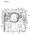
- FIG.2 shows an intermediate state in the tape loading operation for forming the tape path.
- the loading posts 10, 12, 18, 19 and the pinch roller 20, which are omitted from FIG.1 are shown for reference.
- the loading posts 13, 14, 15 on the first carrier 31 and the loading posts 16, 17 on the second carrier 32 reaches the predetermined different positions at the intermediate state of the cassette loading operation, that is at the end stage of the tape loading operation.
- These loading posts 13, 14, 15, 16, 17 are precisely arranged at a predetermined position because the first carrier 31 having the loading posts 13, 14, 15 and the second carrier 32 having the loading posts 16, 17 are pressed against stoppers (not shown) at the predetermined position by springs (not shown).
- the tape path for the tape 4 shown by a solid line in FIG.2 is formed by the tape guide drum 9, the loading posts 13, 14, 15, 16, 17 the pinch roller 20, capstan 21 and the like.
- the tape path has been just established as shown in FIG.2 when the loading posts 13, 14, 15, 16, 17 reach the predetermined positions by the operated loading motor 40. Since the loading motor 40 is still operating in a same rotary direction after the first frame 22 abuts to the second frame 23, the first frame 22 and the second frame 23 are moved together in the same direction shown by the arrow J in FIG.2.
- the loading motor 40 is stopped by an actuated switch means (not shown).
- the recording/reproducing apparatus of the present invention can be constructed in a minimum space to receive the whole mechanism for forming the tape path.
- the recording/reproducing apparatus since the recording/reproducing apparatus has advantage for the reduction in size and weight, the recording/reproducing apparatus can be easily incorporated in a VCR, especially a portable VCR having a camera unit.
- the tape cassette 1 By inserting the tape cassette 1 in only one direction (arrow L in FIG.3) to the cassette guide mechanism of the third frame 24, the tape cassette 1 can be easily loaded to the recording/reproducing apparatus. Therefore, the necessary space for inserting the tape cassette 1 is reduced in size, and the recording/reproducing apparatus is good for incorporating to the portable VCR.
- the recording/reproducing apparatus has an advantage in a simple cassette loading mechanism.
- the simple cassette loading mechanism has only one loading motor 40 which provides the whole necessary driving force, and one spring 37 which controls the first frame 22 and the second frame 23.
- FIG.10 is a plan view showing main parts of a tape loading mechanism of the recording/reproducing apparatus, and shows a tape path 4a in the second embodiment.
- a tape 4 is stretched in front of the tape cassette 1 in a first step of a tape loading operation as shown by the alternate long and short dash line in FIG.10.
- Corresponding parts and components to the first embodiment are shown by the same numerals and marks, and the description thereon made in the first embodiment similarly apply. Differences and features of this second embodiment from the first embodiment are as follows.
- two loading posts 13 and 18, which are provided in the aforementioned first embodiment, are not provided in this recording/reproducing apparatus.
- a loading post 51 is provided in the second embodiment.
- an inclined loading post 17 is arranged outside the opening 7 of the tape cassette 1. Relation of the pinch roller 20 and the capstan 21 are arranged opposite to that of the tape 4 of the aforementioned first embodiment.
- loading posts 10, 12, 51, 14, 15, 16, 19 and the pinch roller 20 are inserted into the opening 7 of the tape cassette 1 when the tape cassette 1 is just put on the first frame 22.
- the other posts 11, 17, a tape guide drum 9 and the capstan 21 are arranged on an outside of the opening 7 to face the stretched tape 4.
- the loading posts 10, 12, 51, 14, 15, 16, 19 and the pinch roller 20 starts to move toward the predetermined positions shown in FIG.10 for forming the tape path 4a.
- the first frame 22 supporting the tape cassette 1 is slid to the inner part of the recording/reproducing apparatus similarly to the aforementioned first embodiment.
- the tape path 4a shown in FIG.10 is formed to be wound around the tape guide drum 9 by the loading posts 10, 12, 51, 14, 15, 16, 19, linked with the sliding operation of the first frame 22.
- above-mentioned recording/reproducing apparatus of the second embodiment is configured by the first frame 22, the second frame 23 and the third frame 24 as same as the aforementioned first embodiment, the loading mechanism of the recording/reproducing apparatus is received in a minimum space regardless of the space for movement of the loading posts 14, 15, 16, 17.
- the capstan 21, the capstan motor 21a and the inclined loading post 17 are mounted on the second frame 23 or the third frame 24, apart from the first embodiment where the capstan 21, the capstan motor 21a and the inclined loading post 17 are mounted on the first frame 22.
- the recording/reproducing apparatus is constructed with a more simple tape loading mechanism in comparison with the first embodiment, since the capstan 21, the capstan motor 21a and the inclined loading post 17 can be selected to slide on a short interval or not to slide on the third frame 24 for forming the tape path.
- the recording/reproducing apparatus has a further more simple tape loading mechanism in comparison with the first embodiment.
- a modified embodiment may be such that the loading posts are moved by using a cam and a lever.
- a modified embodiment may be such that the first frame and the second frame are slid by the other driving mechanism or a manual control of a user in order to reduce the size and save the electric power.
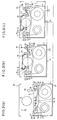
- FIG.11 to FIG.14 are cross-sectional side views showing the recording/reproducing apparatus which is operating on the way of a cassette loading operation.
- FIG.15 and FIG.16 are side views showing main parts of a turning block mechanism of the recording/reproducing apparatus.
- FIG.17 is an exploded perspective view showing the main parts of the turning block mechanism.
- Corresponding parts and components to the first embodiment are shown by the same numerals and marks, and the description thereon made in the first embodiment similarly apply. Differences and features of this third embodiment from the first embodiment are as follows.
- a third frame 24a which supports the first frame 22 and the second frame 23, is formed in box shape as an outer cover of the recording/reproducing apparatus.
- a picture signal processing circuit, an audio signal processing circuit and a system control circuit are provided in the third frame 24a.
- the driving gear 38, the reducing unit 39 and the loading motor 40 are provided on the second frame 23, apart from the first embodiment wherein these are provided on the third frame 24. Therefore, the first gear 22d of the first frame 22 is connected to the loading motor 40 on the second frame 23 through the driving gear 38 and the reducing unit 39 on the second frame 23. The first frame 22 is moved relatively against the second frame 23 by the operated loading motor 40.
- the spring 37 which is provided between the first frame 22 and the second frame 23 for pulling these to each other in the first embodiment and the second embodiment, needs not be provided in the third embodiment.
- the first frame 22 is slidably supported on the second frame 23.
- Two guide pins 27, 28 which are provided on the second frame 23 are engaged in two guide grooves 22a, 22b of the first frame 22, respectively. Therefore, the sliding direction of the first frame 22 is controlled by the engagement between the guide pins 27, 28 and the guide grooves 22a, 22b.
- the second frame 23 is slidably supported on the third frame 24a which is a main body of the recording/reproducing apparatus. Since two guide pins 35, 36 which are provided on the third frame 24a are engaged in the two guide grooves 23a, 23b of the second frame 23, the sliding direction of the second frame 23 is controlled by the engagement between the guide pins 35, 36 and the guide grooves 23a, 23b.
- FIG.11 shows a side view of the recording/reproducing apparatus when the tape cassette 1 is just put on the first frame 22.
- FIG.12 shows a side view of the recording/reproducing apparatus when the first frame 22 is finished to move relatively to the second frame 23.
- FIG.13 shows a side view of the recording/reproducing apparatus when the second frame 23 is finished to move relatively to the third frame 24a, during a turning of a turn-over cover 60.
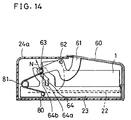
- FIG.14 shows a side view of the recording/reproducing apparatus when the turn-over cover 60 is closed tightly to the third frame 24a, that is when the whole cassette loading operation has been finished.
- the recording/reproducing apparatus is formed in a symmetrical shape with respect to the central axis including the sliding direction of the first frame 22 and second frame 23.
- the turn-over cover 60 which is held to turn by the third frame 24a, is provided to shut the third frame 24a in order to prevent sticking of dust to the main parts, such as the tape cassette 1 and the tape guide drum 9 and the like, in the third frame 24a during recording or reproducing.
- Arms 61 which are provided at both sides of the turn-over cover 60, are pivotably held to the third frame 24a by pivot pins 62 of the arms 61.
- Guide pins 63 which are provided on the arms 61, are engaged with guide grooves 64 which are formed at both side of the second frame 23.
- the sliding interval of the second frame 23 is controlled by the relation between a turning angle of the turn-over cover 60 and a shape of the guide groove 64.
- the guide groove 64 has a straight portion 64a for sliding the second frame 23 by the turning operation of the turnover cover 60 and further a curve portion 64b for turning the turn-over cover 60.
- a helical torsion coil spring 81 is arranged between the guide pin 63 of the turn-over cover 60 and a pin 80 which is provided on both sides of the third frame 24a.
- the helical torsion coil spring 81 which is a so-called toggle spring, energizes to open the turn-over cover 60 in a direction shown by an arrow M in FIG.11 when the turn-over cover 60 is opened entirely from the third frame 24a as shown in FIG.11.
- the helical torsion coil spring 81 energizes to close tightly the turn-over cover 60 in a direction shown by an arrow N in FIG.14.
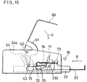
- FIG.15 shows a side view of the recording/reproducing apparatus and shows the turning block mechanism of the recording/reproducing apparatus in a state before the first frame 22 is moved relatively against the second frame 23.
- FIG.16 show a side view of the recording/reproducing apparatus in a state after the first frame 22 is moved relatively against the second frame 23.
- FIG.17 shows an exploded perspective view of main parts of the turning block mechanism.
- a turning block lever 70 and a contact lever 71 are pivotably held by a pin 230 on a side face of the second frame 23.
- a turning block pin 72 which is provided on the turning block lever 70, contacts with a stopper portion 75 of a guide groove 240 of the third frame 24a in the first step of the cassette loading operation shown in FIG.15.
- the turning block lever 70 is energized in a direction Q (FIG.17) by a spring 73 which pushes the second frame 23 (at a point 0 in FIG.17) and the turning block lever 70 (at a point P in FIG.17).
- a spring 74 is arranged so as to push the turning block lever 70 (at a point V in FIG.17) and the contact lever 71 (at a point S in FIG.17). As a result, the contact lever 71 is linked with the turning block lever 70.
- a release pin 76 for pushing the contact lever 71 is provided on the side face of the first frame 22.
- the release pin 76 may be provided on the side face of the cassette guide mechanism for guiding the tape cassette 1 to the first frame 22 as a modified embodiment.
- the first frame 22 is not slid on the second frame 23. If the turn-over cover 60 is turned to shut in a direction shown by an arrow U in FIG.15, the turning block pin 72 abuts to the stopper 75 of the guide groove 240 of the third frame 24a. Therefore, the second frame 23 is prevented from sliding on the third frame 24a before abutting of the first frame 22 to the second frame 23. And the turning operation of the turn-over cover 60 is prohibited under the above-mentioned state shown in FIG.15.
- FIG.12 shows the recording/reproducing apparatus in the state when the first frame 22 finishes its moving relative to the second frame 23.
- the turn-over cover 60 when the turn-over cover 60 is turned in the direction U, the guide pin 63 of the arm 61 presses an edge of the straight portion 64a of the guide grooves 64. Then, the second frame 23 together with the first frame 22 is slid in a direction shown by an arrow R to be received in the inner part of the third frame 24a as shown in FIG.13.
- the turn-over cover 60 can be freely turned around the turning pin 62 without the sliding movement of the second frame 23, since the guide pin 63 for the turn-over cover 60 is guided by the curve portion 64b of the guide groove 64.
- the turn-over cover 60 is locked by a known locking mechanism (not shown) to be closed tightly to the third frame 24a. Therefore, the main components in the recording/reproducing apparatus is covered from outside as shown in FIG.14.
- the turn-over cover 60 is energized to be tightly closed in the closing state of the recording/reproducing apparatus.
- the turn-over cover 60 is in open state, the turn-over cover 60 is energized to be opened by the helical torsion coil spring 81. Therefore, the recording/reproducing apparatus of the third embodiment eliminates the shaking movement in the turning of the turn-over cover 60, and can be operated on a concise and correct movement by the manual operation of the user.
- the recording/reproducing apparatus becomes to a compact size.
- the second frame 23 is moved the innermost space of the recording/reproducing apparatus, there is no redundant vacant space behind the tape guide drum 9. Therefore, after the loading posts 13, 14, 15 pass through the rear space of the tape guide drum 9, the tape loading mechanism for forming the tape path is configured to be received in a possible minimum space.
- the recording/reproducing apparatus of the present invention with regard to all the embodiments, once the first frame 22 which supports the tape cassette 1 is slid in a direction to contact with the second frame 23, thereafter it is further slid together with the second frame 23 in the same direction to be received in the recording/reproducing apparatus. Therefore the space for forming the necessary tape path can be formed as possible minimum.
- the recording/reproducing apparatus is extremely advantageous for the reduction of size.
- the recording/reproducing apparatus of the present invention since the direction of loading the tape cassette 1 to the cassette guide mechanism of the first frame 22 can be selected in a single direction, the recording/reproducing apparatus of the present invention is advantageously incorporated to other apparatus, such as a portable VCR which needs to be as compact as possible.
- the recording/reproducing apparatus since the first frame 22 and the second frame 23 are moved by the closing operation of the turn-over cover 60, the first frame 22 and the second frame 23 are certainly slid by the manual operation of the user. Therefore, the recording/reproducing apparatus is dependable and economical.
- the locking operation for closing the turn-over cover 60 can be constructed independently to be surely operated after the cassette loading operation.
- the turn-over cover of the third embodiment 60 is prevented from turning except when the first frame 22 approaches the second frame 23, the recording/reproducing apparatus is prevented from a break down due to a wrong operation of the user. Therefore, the recording/reproducing apparatus has a high reliability.
- the turn-over cover 60 is energized in an opening direction during opening of the turn-over cover 60, or in a closing direction during shutting of it. Therefore, the opening or closing operation of the turn-over cover 60 is surely performed by the user, and the recording/reproducing apparatus is constructed to have superior handling operation.
Landscapes
- Automatic Tape Cassette Changers (AREA)
- Signal Processing For Digital Recording And Reproducing (AREA)
Description
- The present invention relates to a recording/reproducing apparatus, such as a video cassette recorder (hereinafter abbreviated as VCR) or a digital audio tape recorder (DAT) for recording and reproducing video signals and/or audio signals of a tape cassette which is to be loaded into the recording/reproducing apparatus. The recording/reproducing apparatus records and/or reproduces such signals by drawing a part of tape from the tape cassette into an operating position, and moving it in a predetermined tape path so as to be wound around a tape guide drum.
- In recent years, many VCR have come into wide use as a recording/reproducing apparatus. In the VCR, especially portable VCR incorporated in a camera unit in one body, a user is intensively expecting that such VCR is configured small-sized and light-weighted. Therefore, it is the very important factor to develop a small-sized and light-weight VCR in order to spread the portable VCR.
- In such VCR, it is indispensable for recording and/or reproducing to automatically draw a part of tape from a tape cassette, and to wind the drawn-out tape around a tape guide drum, so that the tape is disposed on a predetermined tape path defined by various loading posts and the like. Therefore, a basic plane view size of such VCR has been almost determined by a diameter of the tape guide drum, dimensions of receiving space for the path-forming means and dimensions of the tape cassette.
- Recently, in order to achieve a small-size and light-weight of VCR, some portable VCR are designed to have a tape guide drum to be inserted into a front opening of the tape cassette when the tape is wound around the tape guide drum. And further, some portable VCR are designed to slide an outer case of the VCR toward an inner space where the path-forming means has passed for winding around the tape guide drum. Example of such a conventional VCR as a recording/reproducing apparatus is shown in the Japanese published examined patent application No. sho 62-180551 (Tokkou Sho 62-180551) which was filed by the same assignee.
- In the conventional recording/reproducing apparatus, when the stretched tape in the tape cassette is wound around the tape guide drum to form a predetermined tape path, the loaded tape cassette and the tape guide drum provided in the apparatus are moved to close each other, and the outer case of the apparatus is slid to shrink. Therefore, the conventional recording/reproducing apparatus is disadvantageous in that a complicated mechanisms for loading operation of the tape cassette and for sliding operation of the outer case must be provided in the apparatus. As a result, it has been so difficult to configure the conventional recording/reproducing apparatus in a small-size and light-weight.
- Finally, EP-A-0 449 658 (date of publication: 02.10.91) discloses a recording/reproducing apparatus comprising a first support means in form of a chassis for supporting a tape cassette and a second support means in form of a chassis for supporting a rotary head drum. However, the cited document neither teaches nor suggests a means for moving the first chassis and the second chassis together. That is, in the cited document, the second chassis in the form of a plate is supported on the first chassis and is slidable into and out of the first chassis. Furthermore, in this cited document, the rotary head drum on the second chassis is inserted into the tape cassette, and a head drum base engages and presses the two reel support chassis. Thereby, the distance between the two reel supports is changed by the movement of the rotary head drum according to the contours of the reel support chassis. Therefore, in this cited document, high working precision is required in manufacturing the two reel support chassis. Moreover, basically, the only requirement for the reel supports is to rotate inherently; however, the reel supports of the cited document are required to move. Therefore a mechanism for driving the reel supports inevitably must be complicated; thereby the recording/reproducing apparatus cannot be achieved with small size, light weight and low costs. Furthermore, since the reels move in the tape cassette, it is necessary that the tape cassette has a complicated construction. And the length of the tape is not increased because of the above-mentioned construction of the recording/reproducing apparatus.
- It is an object of the present invention to provide a recording/reproducing apparatus which is formed in a small-sized and light-weight, and which has a simple mechanism for loading a tape cassette.
- The above-mentioned object is achieved by a recording/reproducing apparatus defined by claim 1.
- The present invention discloses a means for moving the first support means and the second support means together in a first direction after the first support means has been moved in the first direction. In the present invention, it is thereby possible to effectively use a rear space of a tape guide drum arranged for the movement of loading posts. That is, the rear space receives the second support means after the loading posts have passed through the rear space by the operation of the above-mentioned means. Therefore the recording/reproducing apparatus of the present invention can be constructed in a minimum space to receive the whole mechanism for forming the tape path.
- Further features of the present invention are defined by subclaims.
- While the features of the invention are set forth particularly in the appended claims, the invention, both as to organization and content, will be better understood and appreciated, along with other objects and features thereof, from the following detailed description taken in conjunction with the drawings.
- FIG.1 to FIG.3 are plan views showing main parts of a loading mechanism of a recording/reproducing apparatus of a first embodiment in accordance with the present invention.
- FIG.4 is a plan side perspective view showing a known tape cassette to be loaded in the recording/reproducing apparatus.
- FIG.5 is a rear side perspective view showing the tape cassette of FIG.4.
- FIG.6 is a cross-sectional side view showing the tape cassette of FIG.4.
- FIG.7 is a plan view showing main parts of a tape loading mechanism of the recording/reproducing apparatus of the first embodiment in accordance with the present invention.
- FIG.8 is a plan view showing the main parts of the tape loading mechanism on a finished winding operation.
- FIGs.9(a), 9(b),and 9(c) show movements of the tape loading mechanism in a loading operation of the first embodiment.
- FIG.10 is a plan view showing main parts of a recording/reproducing apparatus of a second embodiment in accordance with the present invention.
- FIG.11 to FIG.14 are cross-sectional side views showing a recording/reproducing apparatus of a third embodiment in accordance with the present invention.
- FIG.15 and FIG.16 are side views of the recording/reproducing apparatus of FIG.11 for showing a turning block mechanism.
- FIG.17 is an exploded perspective view of the turning block mechanism of FIG.15.
- It will be recognized that some or all of the Figures are schematic representations for purposes of illustration and do not necessarily depict the actual relative sizes or locations of the elements shown.
- Hereafter, a first embodiment of a recording/reproducing apparatus, such as a portable VCR, etc., of the present invention is described referring to the accompanying drawings of FIGs. 1 to 9.
- FIGs.1 to 3 are plan views showing main parts of a loading mechanism of the recording/reproducing apparatus in accordance with the present invention. FIG.4 is a plan side perspective view showing a tape cassette which is to be loaded to the recording/reproducing apparatus of the present invention. FIG.5 is a rear side perspective view showing the tape cassette of FIG.4. FIG.6 is a cross-sectional side view showing the tape cassette of FIG.4. FIGs.7 and 8 are plan views showing main tape loading mechanism in the cassette loading operation of the recording/reproducing apparatus. FIG.9 shows the movements of the tape loading mechanism in the cassette loading operation of the first embodiment in accordance with the present invention.
- In the first place, a tape cassette 1, which is to be loaded to the recording/reproducing apparatus, is described referring to FIGs.4 to 6.
- In FIG.4, a
tape 4, which is wound around asupply reel 2 as well as a take-up reel in the tape cassette 1, is stretched there between through a pair ofcassette posts stretched tape 4 and thecassette posts tape 4 disposed in the front part of the tape cassette 1 is disposed between alid 5 and aback lid 6, which is situated near the back face of thestretched tape 4 between thecassette posts - As shown in FIG.5, an
opening 7 of the tape cassette 1 is formed on a front side of therear face 1a. The opening 7 of the tape cassette 1 is arranged in a manner to provide therein various loading posts for drawing thestretched tape 4 from the tape cassette 1 to the inner part of the recording/reproducing apparatus when the tape cassette 1 is loaded to the recording/reproducing apparatus. When the tape cassette 1 is loaded into the recording/reproducing apparatus of the first embodiment, a known lid open mechanism (not shown) for opening thelid 5 and theback lid 6 of the tape cassette 1 contacts with aside face 5a of thelid 5, so as to open thelid 5 and theback lid 6 as shown in FIG.6. - In a non-loaded state where the tape cassette 1 is taken out of the recording/reproducing apparatus, the
back lid 6 is arranged at rear side of thelid 5 with thestretched tape 4 in between. Theback lid 6 is supported by asupport plate 5b (FIG.6) of thelid 5, by rotatably jounalling anend portion 6a of theback lid 6 on thesupport plate 5b. Aguide pin 6b of theback lid 6 is engaged with an arc-shapedguide groove 7b which are formed on both side faces 7a of the tape cassette 1, and is guided rotatably by the arc-shapedguide grooves 7b. Therefore, when the tape cassette 1 is loaded to the recording/reproducing apparatus, thelid 5 and theback lid 6 are rotated by the lid open mechanism along a predetermined locus as shown by the alternate long and short dash line in FIG.6 without contact to thetape 4 stretched in front of the tape cassette 1. - When the
lid 5 and theback lid 6 are entirely opened by the lid open mechanism, thelid 5 and theback lid 6 are rotated to expose thetape 4 stretched between the cassette posts 8a and 8b. That is thelid 5 and theback lid 6 are moved for distances longer than the width of thetape 4. Therefore, a knowntape guide drum 9 in the recording/reproducing apparatus can be relatively inserted into theopening 7 of the tape cassette 1 when the tape cassette is loaded to the recording/reproducing apparatus. - Next, movement of main tape loading mechanism in the above-mentioned recording/reproducing apparatus is described with reference to FIG.7 and FIG.8. FIG.7 is the diagrammatic plan view showing an arrangement of main parts of the tape loading mechanism in a first step of a cassette loading operation. FIG.8 is the diagrammatic plan view showing a tape path established by the main parts of the tape loading mechanism in the end step of the cassette loading operation.
- In FIG.7, the
tape 4 of the tape cassette 1, which has been described in the foregoing explanation with reference to FIGs.4 to 6, is stretched in front of the tape cassette 1 in the recording/reproducing apparatus when the tape cassette 1 has just been put on afirst frame 22 in a first step of the cassette loading operation. Thetape guide drum 9 having known rotary heads (not shown) is located inside the recording/reproducing apparatus when the tape cassette 1 is just put on thefirst frame 22 at a position shown in FIG.7. - As shown in FIG.7,
various loading posts capstan 21 are moved into theopening 7 of the tape cassette 1 when the tape cassette 1 is just put to the recording/reproducing apparatus. The other loading posts 11, 18, apinch roller 20 and thetape guide drum 9 are arranged outside theopening 7, facing against the stretchedtape 4. - The recording/reproducing apparatus of the first embodiment comprises the
first frame 22 for supporting the tape cassette 1 and the like, asecond frame 23 providing thetape guide drum 9, and thethird frame 24 supporting thefirst frame 22 and thesecond frame 23. When the tape cassette 1 is just put on thefirst frame 22 in the first step of the cassette loading operation, the innermost end of thefirst frame 22 and the innermost end of thethird frame 24 are positioned to have a predetermined interval A as shown in FIG.7. The necessary mechanism for loading the tape cassette 1 is arranged in a space which is between the innermost faces of thefirst frame 22 and thethird frame 24. - Next, the cassette loading operation of the above-mentioned tape loading mechanism of the recording/reproducing apparatus is described with reference to FIGs.7 and 8.
- As shown in FIG.7, in the first step of the cassette loading operation, the loading posts 10, 11, 12, 18, 19 and the
pinch roller 20 start to move toward the predetermined position shown by the alternate long and short dash lines in FIG.7. In other words, the loading posts 10, 11, 12, 18, 19 and thepinch roller 20 are slid in directions shown by arrows B, C, D, E, F, G, respectively. At the same time, thefirst frame 22 starts to move in a direction shown by an arrow J. As a result, the tape cassette 1 approaches thetape guide drum 9. During the approaching of the tape cassette 1 towards thetape guide drum 9, thetape 4 in the tape cassette 1 is wound around thetape guide drum 9 by motions of the loading posts 13, 14, 15, 16, 17 in a direction shown by an arrow K. Then a predetermined tape path, where thetape 4 is passed around the loading posts and thetape guide drum 9, is established in the recording/reproducing apparatus. FIG.8 shows the establishedtape path 4a for the recording or reproducing in the first embodiment. - FIGs.9(a), 9(b) and 9(c) show three stages in the above-mentioned cassette loading operation of the first embodiment in accordance with the present invention. FIG.9(a) shows the first stage of the cassette loading operation, FIG.9(b) shows the intermediate stage of the cassette loading operation when a tape loading operation is finished, and FIG.9(c) shows the end stage of the cassette loading operation. When the
tape 4 of the tape cassette 1, which is put on thefirst frame 22, is wound around thetape guide drum 9 as shown in FIG.9(b), thefirst frame 22 is slid for an interval II from the first stage shown in FIG.9(a) of the cassette loading operation. And, thefirst frame 22 holding the tape cassette 1 and thesecond frame 23 providing thetape guide drum 9 have been already slid for an interval I from the intermediate stage shown in FIG.9(b), when the tape cassette 1 becomes loaded completely into the recording/reproducing apparatus (FIG.9(c)). Accordingly, when thefirst frame 22 which holds the tape cassette 1 is slid for the interval H+I, the cassette loading operation of the recording/reproducing apparatus has been finished. Since the advancing motion of the interval I is provided, total depth X of the apparatus box can be decreased in comparison with the conventional apparatus. As a result, the compact recording/reproducing apparatus can be obtained. - A loading operation will be described hereinunder with a concrete example shown in FIG.1 to FIG.3 with regard to the above-mentioned recording/reproducing apparatus of the first embodiment. Since a driving mechanism for sliding the above-mentioned loading posts 10, 12, 18, 19 and the
pinch roller 20 is operated by the known prior art, descriptions on the parts of loading ring means, the driving mechanism for sliding the loading posts 10, 12, 18, 19 and so on are omitted from the following description. - FIG.1 is a plan view showing main parts of a cassete loading mechanism in the recording/reproducing apparatus. In FIG.1, a
capstan 21 for driving thetape 4 from thesupply reel 2 to the take-upreel 3 is put on thefirst frame 22. And, on thefirst frame 22, asupply reel stand 25 and a take-up reel stand 26 are provided. Acapstan motor 21a, which is configured integral with thecapstan 21, is provided under thefirst frame 22. Thecapstan 21 is rotated by thecapstan motor 21a in both directions, that is in a clockwise and a counterclockwise in FIG.1. A transmission mechanism for transmitting the turning force to thesupply reel stand 25 and the take-up reel stand 26 from thecaptain motor 21a is provided under thefirst frame 2. Thesupply reel stand 25 and the take-up reel stand 26 can be rotated in a desired direction by changing the rotary direction of thecapstan 21. The rotary direction of thesupply reel stand 25 or the take-upreel stand 26 is decided by using a known art, e.g. a driving gear system (not shown) whereof the position is changed by friction thereof after transmission of the turning force of thecapstan motor 21a to the operation gear through a belt (not shown). Since the transmission mechanism has been known and widely used, an explanation for the transmission mechanism is omitted from the following description. - In the first embodiment, the
first frame 22 comprises a known cassette guide mechanism (not shown) for guiding the tape cassette 1 to be loaded into the recording/reproducing apparatus. Since the cassette guide mechanism is known and widely, an explanation for the cassette guide mechanism is omitted here. - The
first frame 22 having the cassette guide mechanism for guiding the tape cassette 1 to thefirst frame 22 is supported slidably on thethird frame 24. Twoguide grooves first frame 22 are engaged with two guide pins 27, 27 on thethird frame 24, respectively. Therefore, a sliding direction and a sliding interval of thefirst frame 22 are defined by the engagement between theguide grooves pins - On the
second frame 23, the above-mentionedtape guide drum 9, anupper loading ring 29 and alower loading ring 30 shown in FIG.3, and astationary loading post 11 for forming the tape path, are provided as shown in FIG.1. The above-mentioned loading posts 13, 14, 15, 16, 17 for forming the tape path are provided on the loading rings 29, 30. The loading posts 13, 14, 15 are provided on afirst carrier 31 which is mechanically connected to theupper loading ring 29 so as to rotate on a predetermined way. And, the loading posts 16, 17 are provided to asecond carrier 32 which is mechanically connected to thelower loading ring 30 so as to rotate on a predetermined way. Since the loading rings 29, 30 are meshed with asecond gear 22c of thefirst frame 22 through twodouble gears second frame 23, the loading rings 29, 30 are rotated by moving relatively between thefirst frame 22 and thesecond frame 23. - The
second frame 23 is slidably supported on thethird frame 24 similarly to thefirst frame 22. Twoguide grooves second frame 23 are engaged with two guide pins 35, 36 on thethird frame 24, respectively. Therefore, a sliding direction and a sliding interval of thesecond frame 23 are decided by the engagement between theguide grooves second frame 23 is selected in the same direction as thefirst frame 22. The sliding interval of thesecond frame 23 is selected to be shorter than the sliding interval of thefirst frame 22. Aspring 37 is engaged between thefirst frame 22 and thesecond frame 23 so as to pull them to each other. - A
first gear 22d of thefirst frame 22 is connected with aloading motor 40 through adriving gear 38, a reducingunit 39 and a driving belt (not shown) which are mounted on thethird frame 24. Therefore, thefirst frame 22 is slid by the driving force from the operated loadingmotor 40. The movement of thefirst frame 22 is not transmitted to theloading motor 40 because the reducingunit 39 having high reduction ratio is provided therebetween. - Next, the cassette loading operation of the above-mentioned recording/reproducing apparatus is described with reference to FIGs.1 to 3.
- FIG.1 shows a state that the tape cassette 1 is just put on the
first frame 22 by the cassette guide mechanism (not shown). When the tape cassette 1 is just put on thefirst frame 22 as shown in FIG.1, the loading posts 13, 14, 15, 16, 17 are arranged within theopening 7 of the tape cassette 1 as stated before (FIG.7). In the above-mentioned state shown in FIG.1, when theloading motor 40 is operated, the turning force of theloading motor 40 is transmitted to thedriving gear 38 through the driving belt (not shown) and through the reducingunit 39 for reducing the revolution speed. Then thefirst frame 22 starts to slide toward thesecond frame 23, that is toward inner part of the apparatus as shown by an arrow J in FIG.1. At that time, thesecond frame 23 stays at an initial position on thethird frame 24 being pulled by resilience of thespring 37 and stopped of the downward motion in FIG.1 by a known stopper (not shown). - As a result, the
first frame 22 is moved relatively against thesecond frame 23, and the two loading rings 29, 30 are started to rotate in a direction shown by an arc shape arrow K in FIG.1. The revolution speed of theupper loading ring 29 is different from the revolution speed of thelower loading ring 30 because theupper loading ring 29 meshes with an upper gear of thedouble gear 33 and alower loading ring 30 meshes with the lower gear of thedouble gear 33. The upper gear and the lower gear of thedouble gear 33 have each other different number of teeth. Therefore, thefirst carrier 31 on theupper loading ring 29 and thesecond carrier 32 on thelower loading ring 30 are moved to leave gradually from each other because of different revolution speed of the loading rings 29, 30. - FIG.2 shows an intermediate state in the tape loading operation for forming the tape path. In FIG.2, the loading posts 10, 12, 18, 19 and the
pinch roller 20, which are omitted from FIG.1, are shown for reference. As shown in FIG.2, since thefirst carrier 31 and thesecond carrier 32 are rotated at different rotation speed, the loading posts 13, 14, 15 on thefirst carrier 31 and the loading posts 16, 17 on thesecond carrier 32 reaches the predetermined different positions at the intermediate state of the cassette loading operation, that is at the end stage of the tape loading operation. These loading posts 13, 14, 15, 16, 17 are precisely arranged at a predetermined position because thefirst carrier 31 having the loading posts 13, 14, 15 and thesecond carrier 32 having the loading posts 16, 17 are pressed against stoppers (not shown) at the predetermined position by springs (not shown). In the above-mentioned intermediate state of the cassette loading operation, the tape path for thetape 4 shown by a solid line in FIG.2 is formed by thetape guide drum 9, the loading posts 13, 14, 15, 16, 17 thepinch roller 20,capstan 21 and the like. - When the tape path is formed at the intermediate step in the cassette loading operation as shown in FIG.2, a
contact portion 22e of thefirst frame 22 abuts to aprojection 23c of thesecond frame 23, and the function of thespring 37 for pulling thefirst frame 22 is over. As a result, the relative movement between thefirst frame 22 and thesecond frame 23 has been finished, and the two rotary movements of theupper loading ring 29 and thelower loading ring 30 have been also finished. - In the above-mentioned intermediate state of the cassette loading operation, the tape path has been just established as shown in FIG.2 when the loading posts 13, 14, 15, 16, 17 reach the predetermined positions by the operated loading
motor 40. Since theloading motor 40 is still operating in a same rotary direction after thefirst frame 22 abuts to thesecond frame 23, thefirst frame 22 and thesecond frame 23 are moved together in the same direction shown by the arrow J in FIG.2. - When the
first frame 22 and thesecond frame 23 reach a predetermined position as shown in FIG.3, the loadingmotor 40 is stopped by an actuated switch means (not shown). - In the final state of the cassette loading operation, the
first frame 22 and thesecond frame 23 are entirely stopped to slide on thethird frame 24, and the recording/reproducing apparatus having thefirst frame 22, thesecond frame 23 and thethird frame 24 is configured in compact size as shown in FIG.3. In other words, though the rear space of thetape guide drum 9 is arranged for the movement of the loading posts 13, 14, 15, the rear space receives thesecond frame 23 after the loading posts 13, 14, 15 pass through the rear space. Therefore, the recording/reproducing apparatus of the present invention can be constructed in a minimum space to receive the whole mechanism for forming the tape path. - In the above-mentioned description of the recording/reproducing apparatus, the other loading posts 10, 12, 18, 19 and the
pinch roller 20 are not described how to be moved. It would be obvious, however, that these loading posts 10, 12, 18, 19 and thepinch roller 20 may be moved in the predetermined way by known rotary plates having these loading posts 10, 12, 18, 19 and thepinch roller 20 linked with the relative movement between thefirst frame 22 and thesecond frame 23. - According to the above-mentioned recording/reproducing apparatus of the first embodiment, since the recording/reproducing apparatus has advantage for the reduction in size and weight, the recording/reproducing apparatus can be easily incorporated in a VCR, especially a portable VCR having a camera unit. By inserting the tape cassette 1 in only one direction (arrow L in FIG.3) to the cassette guide mechanism of the
third frame 24, the tape cassette 1 can be easily loaded to the recording/reproducing apparatus. Therefore, the necessary space for inserting the tape cassette 1 is reduced in size, and the recording/reproducing apparatus is good for incorporating to the portable VCR. - And further, the recording/reproducing apparatus has an advantage in a simple cassette loading mechanism. The simple cassette loading mechanism has only one
loading motor 40 which provides the whole necessary driving force, and onespring 37 which controls thefirst frame 22 and thesecond frame 23. - Hereafter, a second embodiment of a recording/reproducing apparatus of the present invention is described referring to the accompanying drawings of FIG.10. FIG.10 is a plan view showing main parts of a tape loading mechanism of the recording/reproducing apparatus, and shows a
tape path 4a in the second embodiment. In FIG.10, atape 4 is stretched in front of the tape cassette 1 in a first step of a tape loading operation as shown by the alternate long and short dash line in FIG.10. Corresponding parts and components to the first embodiment are shown by the same numerals and marks, and the description thereon made in the first embodiment similarly apply. Differences and features of this second embodiment from the first embodiment are as follows. - In the second embodiment, two
loading posts loading post 51 is provided in the second embodiment. In the second embodiment, aninclined loading post 17 is arranged outside theopening 7 of the tape cassette 1. Relation of thepinch roller 20 and thecapstan 21 are arranged opposite to that of thetape 4 of the aforementioned first embodiment. - In order to form the
tape path 4a in the second embodiment, loading posts 10, 12, 51, 14, 15, 16, 19 and thepinch roller 20 are inserted into theopening 7 of the tape cassette 1 when the tape cassette 1 is just put on thefirst frame 22. At that time, theother posts tape guide drum 9 and thecapstan 21 are arranged on an outside of theopening 7 to face the stretchedtape 4. - Next, the tape loading operation of the above-mentioned second embodiment of the recording/reproducing apparatus is described with reference to FIG.10.
- After the tape cassette 1 is put on the
first frame 22 of the recording/reproducing apparatus, the loading posts 10, 12, 51, 14, 15, 16, 19 and thepinch roller 20 starts to move toward the predetermined positions shown in FIG.10 for forming thetape path 4a. At that time, thefirst frame 22 supporting the tape cassette 1 is slid to the inner part of the recording/reproducing apparatus similarly to the aforementioned first embodiment. As a result, thetape path 4a shown in FIG.10 is formed to be wound around thetape guide drum 9 by the loading posts 10, 12, 51, 14, 15, 16, 19, linked with the sliding operation of thefirst frame 22. - Since, above-mentioned recording/reproducing apparatus of the second embodiment is configured by the
first frame 22, thesecond frame 23 and thethird frame 24 as same as the aforementioned first embodiment, the loading mechanism of the recording/reproducing apparatus is received in a minimum space regardless of the space for movement of the loading posts 14, 15, 16, 17. - In the second embodiment, the
capstan 21, thecapstan motor 21a and the inclined loading post 17 are mounted on thesecond frame 23 or thethird frame 24, apart from the first embodiment where thecapstan 21, thecapstan motor 21a and the inclined loading post 17 are mounted on thefirst frame 22. As a result, the recording/reproducing apparatus is constructed with a more simple tape loading mechanism in comparison with the first embodiment, since thecapstan 21, thecapstan motor 21a and the inclined loading post 17 can be selected to slide on a short interval or not to slide on thethird frame 24 for forming the tape path. - And further, in the second embodiment, number of loading posts moving around the
tape guide drum 9 are less by two than that of the first embodiment. Therefore, the recording/reproducing apparatus has a further more simple tape loading mechanism in comparison with the first embodiment. - Apart from the above-mentioned first and second embodiments wherein the loading posts 13, 14, 15, 16, 17 for forming the tape path are moved by the
upper loading ring 29 and thelower loading ring 30, a modified embodiment may be such that the loading posts are moved by using a cam and a lever. - Further apart from the above-mentioned first and second embodiments wherein the
first frame 22 and thesecond frame 23 are slid on thethird frame 24 by the loadingmotor 40, a modified embodiment may be such that the first frame and the second frame are slid by the other driving mechanism or a manual control of a user in order to reduce the size and save the electric power. - Hereafter, a third embodiment of a recording/reproducing apparatus of the present invention is described referring to the accompanying drawings of FIGs.11 to 17. FIG.11 to FIG.14 are cross-sectional side views showing the recording/reproducing apparatus which is operating on the way of a cassette loading operation. FIG.15 and FIG.16 are side views showing main parts of a turning block mechanism of the recording/reproducing apparatus. FIG.17 is an exploded perspective view showing the main parts of the turning block mechanism. Corresponding parts and components to the first embodiment are shown by the same numerals and marks, and the description thereon made in the first embodiment similarly apply. Differences and features of this third embodiment from the first embodiment are as follows.
- In the third embodiment, a
third frame 24a, which supports thefirst frame 22 and thesecond frame 23, is formed in box shape as an outer cover of the recording/reproducing apparatus. A picture signal processing circuit, an audio signal processing circuit and a system control circuit are provided in thethird frame 24a. - In the third embodiment, the
driving gear 38, the reducingunit 39 and theloading motor 40 are provided on thesecond frame 23, apart from the first embodiment wherein these are provided on thethird frame 24. Therefore, thefirst gear 22d of thefirst frame 22 is connected to theloading motor 40 on thesecond frame 23 through thedriving gear 38 and the reducingunit 39 on thesecond frame 23. Thefirst frame 22 is moved relatively against thesecond frame 23 by the operated loadingmotor 40. - As a result, the
spring 37, which is provided between thefirst frame 22 and thesecond frame 23 for pulling these to each other in the first embodiment and the second embodiment, needs not be provided in the third embodiment. Thefirst frame 22 is slidably supported on thesecond frame 23. Two guide pins 27, 28 which are provided on thesecond frame 23 are engaged in twoguide grooves first frame 22, respectively. Therefore, the sliding direction of thefirst frame 22 is controlled by the engagement between the guide pins 27, 28 and theguide grooves - And, the
second frame 23 is slidably supported on thethird frame 24a which is a main body of the recording/reproducing apparatus. Since two guide pins 35, 36 which are provided on thethird frame 24a are engaged in the twoguide grooves second frame 23, the sliding direction of thesecond frame 23 is controlled by the engagement between the guide pins 35, 36 and theguide grooves - Next, the cassette loading operation of the third embodiment of the present invention is described with reference to FIGs.11 to 14. FIG.11 shows a side view of the recording/reproducing apparatus when the tape cassette 1 is just put on the
first frame 22. FIG.12 shows a side view of the recording/reproducing apparatus when thefirst frame 22 is finished to move relatively to thesecond frame 23. FIG.13 shows a side view of the recording/reproducing apparatus when thesecond frame 23 is finished to move relatively to thethird frame 24a, during a turning of a turn-over cover 60. FIG.14 shows a side view of the recording/reproducing apparatus when the turn-over cover 60 is closed tightly to thethird frame 24a, that is when the whole cassette loading operation has been finished. The recording/reproducing apparatus is formed in a symmetrical shape with respect to the central axis including the sliding direction of thefirst frame 22 andsecond frame 23. - In FIG.11, the turn-
over cover 60, which is held to turn by thethird frame 24a, is provided to shut thethird frame 24a in order to prevent sticking of dust to the main parts, such as the tape cassette 1 and thetape guide drum 9 and the like, in thethird frame 24a during recording or reproducing. -
Arms 61, which are provided at both sides of the turn-over cover 60, are pivotably held to thethird frame 24a bypivot pins 62 of thearms 61. Guide pins 63, which are provided on thearms 61, are engaged withguide grooves 64 which are formed at both side of thesecond frame 23. As a result, the turning operation of the turn-over cover 60 is linked with the sliding operation of thesecond frame 23. - The sliding interval of the
second frame 23 is controlled by the relation between a turning angle of the turn-over cover 60 and a shape of theguide groove 64. Theguide groove 64 has astraight portion 64a for sliding thesecond frame 23 by the turning operation of theturnover cover 60 and further acurve portion 64b for turning the turn-over cover 60. - A helical
torsion coil spring 81 is arranged between theguide pin 63 of the turn-over cover 60 and apin 80 which is provided on both sides of thethird frame 24a. The helicaltorsion coil spring 81, which is a so-called toggle spring, energizes to open the turn-over cover 60 in a direction shown by an arrow M in FIG.11 when the turn-over cover 60 is opened entirely from thethird frame 24a as shown in FIG.11. On the contrary, when the turn-over cover 60 is shut to thethird frame 24a as shown in FIG.14, the helicaltorsion coil spring 81 energizes to close tightly the turn-over cover 60 in a direction shown by an arrow N in FIG.14. - FIG.15 shows a side view of the recording/reproducing apparatus and shows the turning block mechanism of the recording/reproducing apparatus in a state before the
first frame 22 is moved relatively against thesecond frame 23. FIG.16 show a side view of the recording/reproducing apparatus in a state after thefirst frame 22 is moved relatively against thesecond frame 23. FIG.17 shows an exploded perspective view of main parts of the turning block mechanism. - As shown in FIG.17, a turning
block lever 70 and acontact lever 71 are pivotably held by apin 230 on a side face of thesecond frame 23. Aturning block pin 72, which is provided on theturning block lever 70, contacts with astopper portion 75 of aguide groove 240 of thethird frame 24a in the first step of the cassette loading operation shown in FIG.15. The turningblock lever 70 is energized in a direction Q (FIG.17) by aspring 73 which pushes the second frame 23 (at a point 0 in FIG.17) and the turning block lever 70 (at a point P in FIG.17). And, aspring 74 is arranged so as to push the turning block lever 70 (at a point V in FIG.17) and the contact lever 71 (at a point S in FIG.17). As a result, thecontact lever 71 is linked with the turningblock lever 70. In FIG.15, arelease pin 76 for pushing thecontact lever 71 is provided on the side face of thefirst frame 22. Therelease pin 76 may be provided on the side face of the cassette guide mechanism for guiding the tape cassette 1 to thefirst frame 22 as a modified embodiment. - In the first step of the cassette loading operation as shown in FIG.15, the
first frame 22 is not slid on thesecond frame 23. If the turn-over cover 60 is turned to shut in a direction shown by an arrow U in FIG.15, theturning block pin 72 abuts to thestopper 75 of theguide groove 240 of thethird frame 24a. Therefore, thesecond frame 23 is prevented from sliding on thethird frame 24a before abutting of thefirst frame 22 to thesecond frame 23. And the turning operation of the turn-over cover 60 is prohibited under the above-mentioned state shown in FIG.15. - As shown in FIG.16, when the
first frame 22 is finished its sliding on thesecond frame 23, that is when the relative movement between thefirst frame 22 and thesecond frame 23 finishes, therelease pin 76 which slides with thefirst frame 22 presses contactlever 71 to rotate it counterclockwise in FIG.16. And, the turningblock lever 70 is turned by thespring 74 which connects between thecontact lever 71 and the turningblock lever 70. As a result, theturning block pin 72 is released from thestopper 75, and thesecond frame 23 can be slid on thethird frame 24a by the shutting operation of the turn-over cover 60. - Next, the cassette loading operation in the third embodiment of the recording/reproducing apparatus is described with reference to FIGs.12 to 14.
- FIG.12 shows the recording/reproducing apparatus in the state when the
first frame 22 finishes its moving relative to thesecond frame 23. In FIG.12, when the turn-over cover 60 is turned in the direction U, theguide pin 63 of thearm 61 presses an edge of thestraight portion 64a of theguide grooves 64. Then, thesecond frame 23 together with thefirst frame 22 is slid in a direction shown by an arrow R to be received in the inner part of thethird frame 24a as shown in FIG.13. - After the recording/reproducing apparatus comes to the position shown in FIG.13, the turn-
over cover 60 can be freely turned around the turningpin 62 without the sliding movement of thesecond frame 23, since theguide pin 63 for the turn-over cover 60 is guided by thecurve portion 64b of theguide groove 64. In the final state of the cassette loading operation as shown in FIG.14, the turn-over cover 60 is locked by a known locking mechanism (not shown) to be closed tightly to thethird frame 24a. Therefore, the main components in the recording/reproducing apparatus is covered from outside as shown in FIG.14. - In FIG.14, since the helical
torsion coil spring 81 is provided to spread between theguide pin 63 fixed to thearm 61 and thepin 80 fixed to thethird frame 24a, the turn-over cover 60 is energized to be tightly closed in the closing state of the recording/reproducing apparatus. On the contrary, when the turn-over cover 60 is in open state, the turn-over cover 60 is energized to be opened by the helicaltorsion coil spring 81. Therefore, the recording/reproducing apparatus of the third embodiment eliminates the shaking movement in the turning of the turn-over cover 60, and can be operated on a concise and correct movement by the manual operation of the user. - As will be understood from the foregoing description, after finish of the loading operation in the whole mechanism of the recording/reproducing apparatus, the recording/reproducing apparatus becomes to a compact size. In other words, since the
second frame 23 is moved the innermost space of the recording/reproducing apparatus, there is no redundant vacant space behind thetape guide drum 9. Therefore, after the loading posts 13, 14, 15 pass through the rear space of thetape guide drum 9, the tape loading mechanism for forming the tape path is configured to be received in a possible minimum space. - According to the above-mentioned recording/reproducing apparatus of the present invention, with regard to all the embodiments, once the
first frame 22 which supports the tape cassette 1 is slid in a direction to contact with thesecond frame 23, thereafter it is further slid together with thesecond frame 23 in the same direction to be received in the recording/reproducing apparatus. Therefore the space for forming the necessary tape path can be formed as possible minimum. The recording/reproducing apparatus is extremely advantageous for the reduction of size. - With regard to all the embodiments of the recording/reproducing apparatus in accordance with the present invention, since the direction of loading the tape cassette 1 to the cassette guide mechanism of the
first frame 22 can be selected in a single direction, the recording/reproducing apparatus of the present invention is advantageously incorporated to other apparatus, such as a portable VCR which needs to be as compact as possible. - In the third embodiment of the recording/reproducing apparatus in accordance with the present invention, since the
first frame 22 and thesecond frame 23 are moved by the closing operation of the turn-over cover 60, thefirst frame 22 and thesecond frame 23 are certainly slid by the manual operation of the user. Therefore, the recording/reproducing apparatus is dependable and economical. - Since the turning operation of the turn-
over cover 60 of the third embodiment is finished after the whole movements for the cassette loading operation are finished, the locking operation for closing the turn-over cover 60 can be constructed independently to be surely operated after the cassette loading operation. - And further, since the turn-over cover of the
third embodiment 60 is prevented from turning except when thefirst frame 22 approaches thesecond frame 23, the recording/reproducing apparatus is prevented from a break down due to a wrong operation of the user. Therefore, the recording/reproducing apparatus has a high reliability. - And further, in the third embodiment, the turn-
over cover 60 is energized in an opening direction during opening of the turn-over cover 60, or in a closing direction during shutting of it. Therefore, the opening or closing operation of the turn-over cover 60 is surely performed by the user, and the recording/reproducing apparatus is constructed to have superior handling operation.
Claims (11)
- A recording/reproducing apparatus comprising:a first support means (22) for supporting a tape cassette (1),a second support means (23) for supporting a tape guide drum (9) which has at least one rotary head,a third support means (24) for supporting said first support means (22) and said second support means (23),a first movement means (38, 39, 40) which moves said first support means (22) relative to said second support means (23) in a first direction,a second movement means (38, 39, 40) which moves said second support means (23) relative to said third support means (24) in said first direction, anda means (38, 39, 40) for moving said first support means (22) and said second support means (23) together in said first direction after said first support means (22) has been moving in said first direction.
- A recording/reproducing apparatus in accordance with claim 1, wherein
said first support means (22) has thereon at least a portion of a tape driving means which drives a tape (4) by rotating a reel in a tape cassette (1). - A recording/reproducing apparatus in accordance with claim 1, wherein
said second support means (23) has thereon at least a portion of a path-forming means which predetermines a tape path by means of drawing a tape (4) from said tape cassette (1) to the outside of said tape cassette (1) and winding it around said tape guide drum (9) in a predetermined angle. - A recording/reproducing apparatus in accordance with claim 1, wherein
said third support means (24) has at least one of said first movement means (38, 39, 40). - A recording/reproducing apparatus in accordance with claim 1, wherein
said first direction is a direction of inserting said tape cassette (1) for loading into said recording/ reproducing apparatus. - A recording/reproducing apparatus in accordance with claim 1, wherein
said path-forming means (29, 30, 31, 32) is operated by said relative movement between said first support means (22) and said second support means (23). - A recording/reproducing apparatus in accordance with claim 1, further comprising:
a spring means (37) which pulls together said first support means (22) and said second support means (23) for stopping said second movement means (38, 39, 40) by a resilience of said spring means (37) when said first support means (22) is moved in said first direction relative to said second support means (23) by said first movement means (38, 39, 40). - A recording/reproducing apparatus in accordance with claim 1, further comprising:
a turn-over cover (60) which tightly covers said third support means (24), said turn-over cover (60) having a closing movement which slides said first support means (22) and second support means (23) to be received in said third support means (24), and said turn-over cover (60) having an opening movement which slides said first support means (22) and said second support means (23) to be projected from said third support means (24). - A recording/reproducing apparatus in accordance with claim 8, wherein
said closing movement of said third support means (24) by said turn-over cover (60) is completed after said receiving of said first support means (22) and said second support means (23) in said third support means (24). - A recording/reproducing apparatus in accordance with claim 8, further comprising:
an energizing means (81) which energizes said turn-over cover (60) closing movement and said turn-over cover (60) opening movement. - A recording/reproducing apparatus in accordance with claim 8, further comprising:
a turning block means (70, 71, 72, 73, 74) which prevents a turning of said turn-over cover (60) except when said first support means (22) approaches said second support means (23) by said first movement means (38, 39, 40).
Applications Claiming Priority (2)
| Application Number | Priority Date | Filing Date | Title |
|---|---|---|---|
| JP77526/91 | 1991-04-10 | ||
| JP3077526A JP2906719B2 (en) | 1991-04-10 | 1991-04-10 | Recording and playback device |
Publications (3)
| Publication Number | Publication Date |
|---|---|
| EP0508384A2 EP0508384A2 (en) | 1992-10-14 |
| EP0508384A3 EP0508384A3 (en) | 1992-12-02 |
| EP0508384B1 true EP0508384B1 (en) | 1997-11-19 |
Family
ID=13636420
Family Applications (1)
| Application Number | Title | Priority Date | Filing Date |
|---|---|---|---|
| EP92106014A Expired - Lifetime EP0508384B1 (en) | 1991-04-10 | 1992-04-07 | Recording/reproducing apparatus |
Country Status (5)
| Country | Link |
|---|---|
| US (1) | US5321565A (en) |
| EP (1) | EP0508384B1 (en) |
| JP (1) | JP2906719B2 (en) |
| KR (1) | KR960000122B1 (en) |
| DE (1) | DE69223171T2 (en) |
Families Citing this family (9)
| Publication number | Priority date | Publication date | Assignee | Title |
|---|---|---|---|---|
| JPH05128647A (en) * | 1991-11-05 | 1993-05-25 | Sony Corp | Brake mechanism in tape player |
| KR940011672B1 (en) * | 1992-06-20 | 1994-12-23 | 주식회사 금성사 | Head drum protecting device for magnetic recording device |
| US5818048A (en) * | 1992-07-15 | 1998-10-06 | Optix Lp | Rapid non-invasive optical analysis using broad bandpass spectral processing |
| JPH06223554A (en) * | 1993-01-26 | 1994-08-12 | Sony Corp | Magnetic recording and reproducing device |
| JP3460261B2 (en) * | 1993-09-20 | 2003-10-27 | 株式会社日立製作所 | Tape mounting device and magnetic transducer |
| JPH07254195A (en) * | 1994-03-17 | 1995-10-03 | Hitachi Ltd | Cassette loading mechanism for recording/producing device |
| US5715123A (en) * | 1994-06-20 | 1998-02-03 | Koo; Kah On | Cassette drive apparatus and method using a tape engager insertable into a lateral access opening of an audio cassette |
| US6157512A (en) * | 1997-09-09 | 2000-12-05 | Canon Kabushiki Kaisha | Recording and/or reproducing apparatus including tape loading mechanism with speed control of tape loading guides |
| US20060224057A1 (en) * | 2003-10-21 | 2006-10-05 | Oculir, Inc. | Methods for non-invasive analyte measurement |
Family Cites Families (11)
| Publication number | Priority date | Publication date | Assignee | Title |
|---|---|---|---|---|
| JPS57212651A (en) * | 1981-06-24 | 1982-12-27 | Matsushita Electric Ind Co Ltd | Magnetic recording and reproducing device |
| JPS59171070A (en) * | 1983-03-18 | 1984-09-27 | Matsushita Electric Ind Co Ltd | Recording and reproducing device |
| JPS60194793U (en) * | 1984-06-01 | 1985-12-25 | ソニー株式会社 | cassette tape recorder |
| JP2545358B2 (en) * | 1986-01-18 | 1996-10-16 | 株式会社日立製作所 | Rotating head type magnetic recording / reproducing device |
| JPS62180551A (en) * | 1986-02-03 | 1987-08-07 | Matsushita Electric Ind Co Ltd | Recording and reproducing device |
| DE3779668T2 (en) * | 1986-02-03 | 1992-12-10 | Matsushita Electric Ind Co Ltd | RECORDING AND / OR PLAYBACK DEVICE. |
| EP0307917B1 (en) * | 1987-09-17 | 1992-02-19 | Sanyo Electric Co., Ltd. | Front door mechanism for signal recording-reproducing apparatus for use with cassette |
| US4985789A (en) * | 1987-10-02 | 1991-01-15 | Sanyo Electric Co., Ltd. | Signal recording-reproducing apparatus for use with cassette |
| JP2644888B2 (en) * | 1989-04-24 | 1997-08-25 | 株式会社日立製作所 | Cassette mounting device |
| JP2712668B2 (en) * | 1989-12-06 | 1998-02-16 | ソニー株式会社 | Tape player with rotating head |
| US5327306A (en) * | 1990-03-30 | 1994-07-05 | Sony Corporation | Compact magnetic recording and reproducing device having movable reels and reel spindles |
-
1991
- 1991-04-10 JP JP3077526A patent/JP2906719B2/en not_active Expired - Fee Related
-
1992
- 1992-04-07 EP EP92106014A patent/EP0508384B1/en not_active Expired - Lifetime
- 1992-04-07 DE DE69223171T patent/DE69223171T2/en not_active Expired - Fee Related
- 1992-04-08 US US07/866,017 patent/US5321565A/en not_active Expired - Fee Related
- 1992-04-09 KR KR1019920005909A patent/KR960000122B1/en not_active IP Right Cessation
Also Published As
| Publication number | Publication date |
|---|---|
| US5321565A (en) | 1994-06-14 |
| DE69223171T2 (en) | 1998-05-28 |
| KR960000122B1 (en) | 1996-01-03 |
| JP2906719B2 (en) | 1999-06-21 |
| EP0508384A3 (en) | 1992-12-02 |
| JPH04311866A (en) | 1992-11-04 |
| EP0508384A2 (en) | 1992-10-14 |
| KR920020447A (en) | 1992-11-21 |
| DE69223171D1 (en) | 1998-01-02 |
Similar Documents
| Publication | Publication Date | Title |
|---|---|---|
| EP0310114B1 (en) | Signal recording-reproducing apparatus for use with cassette | |
| JPS59171070A (en) | Recording and reproducing device | |
| US5025331A (en) | Tape casette loading system compatible with two different sized cassettes | |
| EP0508384B1 (en) | Recording/reproducing apparatus | |
| US5327306A (en) | Compact magnetic recording and reproducing device having movable reels and reel spindles | |
| US4868693A (en) | Magnetic recording and/or reproducing apparatus | |
| EP0232161B1 (en) | Arrangement of recording and/or reproducing apparatus | |
| EP0356184B1 (en) | Tape-loading mechanism for a magnetic recording/reproducing apparatus for selective use of tape cassettes of two different sizes | |
| US5731925A (en) | Recording and/or reproducing apparatus having tape pull-out members with mutually intersecting movement paths | |
| US5034832A (en) | Adaptor for a small-sized tape cassette | |
| US5258881A (en) | Tape cassette loading system in recording and/or reproducing apparatus | |
| JPH03283158A (en) | Tape cassette | |
| JPH02210655A (en) | Recording and/or reproducing device | |
| JP3036205B2 (en) | Recording and playback device | |
| JPS6053380B2 (en) | magnetic tape device | |
| JPH08339595A (en) | Tape loading mechanism and recording or reproducing device | |
| JP2536259B2 (en) | Magnetic recording / reproducing device | |
| JP3348588B2 (en) | Recording and playback device | |
| US6044233A (en) | Apparatus having film cartridge holding device | |
| JP2672590B2 (en) | Tape recorder device | |
| JP2572437B2 (en) | Magnetic recording / reproducing device | |
| JPH0239027B2 (en) | ||
| JPH03283131A (en) | Magnetic recording and reproducing device | |
| JPH02165458A (en) | Recording of reproducing device | |
| JPH02123552A (en) | Tape pulling out mechanism |
Legal Events
| Date | Code | Title | Description |
|---|---|---|---|
| PUAI | Public reference made under article 153(3) epc to a published international application that has entered the european phase |
Free format text: ORIGINAL CODE: 0009012 |
|
| PUAL | Search report despatched |
Free format text: ORIGINAL CODE: 0009013 |
|
| 17P | Request for examination filed |
Effective date: 19920407 |
|
| AK | Designated contracting states |
Kind code of ref document: A2 Designated state(s): DE FR GB |
|
| AK | Designated contracting states |
Kind code of ref document: A3 Designated state(s): DE FR GB |
|
| 17Q | First examination report despatched |
Effective date: 19950515 |
|
| GRAG | Despatch of communication of intention to grant |
Free format text: ORIGINAL CODE: EPIDOS AGRA |
|
| GRAH | Despatch of communication of intention to grant a patent |
Free format text: ORIGINAL CODE: EPIDOS IGRA |
|
| GRAH | Despatch of communication of intention to grant a patent |
Free format text: ORIGINAL CODE: EPIDOS IGRA |
|
| GRAA | (expected) grant |
Free format text: ORIGINAL CODE: 0009210 |
|
| AK | Designated contracting states |
Kind code of ref document: B1 Designated state(s): DE FR GB |
|
| REF | Corresponds to: |
Ref document number: 69223171 Country of ref document: DE Date of ref document: 19980102 |
|
| ET | Fr: translation filed | ||
| PLBE | No opposition filed within time limit |
Free format text: ORIGINAL CODE: 0009261 |
|
| STAA | Information on the status of an ep patent application or granted ep patent |
Free format text: STATUS: NO OPPOSITION FILED WITHIN TIME LIMIT |
|
| 26N | No opposition filed | ||
| REG | Reference to a national code |
Ref country code: GB Ref legal event code: IF02 |
|
| PGFP | Annual fee paid to national office [announced via postgrant information from national office to epo] |
Ref country code: GB Payment date: 20030402 Year of fee payment: 12 |
|
| PG25 | Lapsed in a contracting state [announced via postgrant information from national office to epo] |
Ref country code: GB Free format text: LAPSE BECAUSE OF NON-PAYMENT OF DUE FEES Effective date: 20040407 |
|
| PGFP | Annual fee paid to national office [announced via postgrant information from national office to epo] |
Ref country code: FR Payment date: 20040408 Year of fee payment: 13 |
|
| PGFP | Annual fee paid to national office [announced via postgrant information from national office to epo] |
Ref country code: DE Payment date: 20040415 Year of fee payment: 13 |
|
| GBPC | Gb: european patent ceased through non-payment of renewal fee | ||
| PG25 | Lapsed in a contracting state [announced via postgrant information from national office to epo] |
Ref country code: DE Free format text: LAPSE BECAUSE OF NON-PAYMENT OF DUE FEES Effective date: 20051101 |
|
| PG25 | Lapsed in a contracting state [announced via postgrant information from national office to epo] |
Ref country code: FR Free format text: LAPSE BECAUSE OF NON-PAYMENT OF DUE FEES Effective date: 20051230 |
|
| REG | Reference to a national code |
Ref country code: FR Ref legal event code: ST Effective date: 20051230 |