EP0507834B1 - Flywheel attachment - Google Patents
Flywheel attachment Download PDFInfo
- Publication number
- EP0507834B1 EP0507834B1 EP91901945A EP91901945A EP0507834B1 EP 0507834 B1 EP0507834 B1 EP 0507834B1 EP 91901945 A EP91901945 A EP 91901945A EP 91901945 A EP91901945 A EP 91901945A EP 0507834 B1 EP0507834 B1 EP 0507834B1
- Authority
- EP
- European Patent Office
- Prior art keywords
- crankshaft
- turbine
- gear wheel
- engine
- flywheel
- Prior art date
- Legal status (The legal status is an assumption and is not a legal conclusion. Google has not performed a legal analysis and makes no representation as to the accuracy of the status listed.)
- Expired - Lifetime
Links
- 230000005540 biological transmission Effects 0.000 claims abstract description 23
- 238000002485 combustion reaction Methods 0.000 claims abstract description 21
- 150000001875 compounds Chemical class 0.000 claims abstract description 12
- 239000007789 gas Substances 0.000 claims abstract description 10
- 238000004519 manufacturing process Methods 0.000 abstract description 6
- 238000012423 maintenance Methods 0.000 abstract description 5
- 230000008901 benefit Effects 0.000 abstract description 3
- 238000005516 engineering process Methods 0.000 abstract description 2
- 230000008878 coupling Effects 0.000 description 20
- 238000010168 coupling process Methods 0.000 description 20
- 238000005859 coupling reaction Methods 0.000 description 20
- 230000000712 assembly Effects 0.000 description 5
- 238000000429 assembly Methods 0.000 description 5
- 239000007858 starting material Substances 0.000 description 5
- 230000000694 effects Effects 0.000 description 2
- 230000010349 pulsation Effects 0.000 description 2
- 230000008439 repair process Effects 0.000 description 2
- 238000004891 communication Methods 0.000 description 1
- 238000010276 construction Methods 0.000 description 1
- 230000002349 favourable effect Effects 0.000 description 1
- 238000000034 method Methods 0.000 description 1
- 238000012986 modification Methods 0.000 description 1
- 230000004048 modification Effects 0.000 description 1
- 230000001360 synchronised effect Effects 0.000 description 1
Images
Classifications
-
- F—MECHANICAL ENGINEERING; LIGHTING; HEATING; WEAPONS; BLASTING
- F02—COMBUSTION ENGINES; HOT-GAS OR COMBUSTION-PRODUCT ENGINE PLANTS
- F02B—INTERNAL-COMBUSTION PISTON ENGINES; COMBUSTION ENGINES IN GENERAL
- F02B37/00—Engines characterised by provision of pumps driven at least for part of the time by exhaust
- F02B37/005—Exhaust driven pumps being combined with an exhaust driven auxiliary apparatus, e.g. a ventilator
-
- F—MECHANICAL ENGINEERING; LIGHTING; HEATING; WEAPONS; BLASTING
- F02—COMBUSTION ENGINES; HOT-GAS OR COMBUSTION-PRODUCT ENGINE PLANTS
- F02B—INTERNAL-COMBUSTION PISTON ENGINES; COMBUSTION ENGINES IN GENERAL
- F02B41/00—Engines characterised by special means for improving conversion of heat or pressure energy into mechanical power
- F02B41/02—Engines with prolonged expansion
- F02B41/10—Engines with prolonged expansion in exhaust turbines
-
- Y—GENERAL TAGGING OF NEW TECHNOLOGICAL DEVELOPMENTS; GENERAL TAGGING OF CROSS-SECTIONAL TECHNOLOGIES SPANNING OVER SEVERAL SECTIONS OF THE IPC; TECHNICAL SUBJECTS COVERED BY FORMER USPC CROSS-REFERENCE ART COLLECTIONS [XRACs] AND DIGESTS
- Y02—TECHNOLOGIES OR APPLICATIONS FOR MITIGATION OR ADAPTATION AGAINST CLIMATE CHANGE
- Y02T—CLIMATE CHANGE MITIGATION TECHNOLOGIES RELATED TO TRANSPORTATION
- Y02T10/00—Road transport of goods or passengers
- Y02T10/10—Internal combustion engine [ICE] based vehicles
- Y02T10/12—Improving ICE efficiencies
Definitions
- the present invention relates to an internal combustion engine assembly of the compound type for vehicles, comprising an internal combustion engine, a turbine, and a crankshaft issuing from the engine, the turbine being designed to be driven by exhaust gases from the engine.
- turbochargers consisting of a turbine which is driven by the exhaust and is mechanically coupled to a compressor designed to compress the combustion air for supercharging the engine.
- turbochargers have been developed and refined and have thereby attained a high level of adjustability and operational reliability. Nevertheless, a large amount of energy still remains in the exhaust gases after leaving the turbine.
- a method for utilising at least some of this surplus energy is to arrange, in series with and downstream of this first turbine, a second turbine driven by the exhaust gases. If this second turbine is in some way coupled so that it transmits mechanically some of the surplus energy to the crankshaft of the engine or to transmissions connected thereto, a so-called turbocompound system is obtained.
- Such systems are previously known, for example from American Patent Specification 4,586,337 (US Cl.60-605) and published international patent application WO 86/00,665 (IPC4 Cl. F02B 41/10,37/00, 67/00). These two specifications illustrate exhaust turbines which, via a long shaft, transmit the energy obtained from the exhaust to the crankshaft via the timing gears of the camshaft transmission.
- An object of the present invention is to provide a possibility of transmitting the energy from the turbine to the crankshaft without having to modify the flywheel, particularly in respect of the ring gear for the starter, or transmitting the energy to the crankshaft via the camshaft timing gears. Another object is to be able to use one and the same base engine in the engine program, which base engine can be used with or without compound addition, and where the only component needing to be changed in the base engine is a flywheel casing.
- a further object of the invention is to provide an internal combustion engine assembly of the compound type, which, in comparison with previously known arrangements of the same type, affords advantages in terms of manufacturing, assembly and maintenance technology.
- the assembly according to the invention is characterised by the fact that, on an endplate secured to the crankshaft, a gear wheel forming part of the transmission is arranged in a rotationally fixed manner, and by the fact that there is formed on the gear wheel a flange which functions as an extension of the crankshaft, directed from the endplate, and an attachment for a flywheel, by means of which the internal combustion engine assembly permits a simple change-over between, on the one hand, manufacture of engine assemblies with turbocompound addition where the gear wheel for the transmission of the turbine is arranged between the endplate of the crankshaft and the flywheel and, on the other hand, manufacture of engine assemblies without turbocompound addition where the flywheel is directly secured against the endplate of the crankshaft.
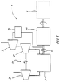
- FIG 1 shows diagrammatically an internal combustion engine assembly according to the invention.
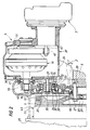
- FIG. 2 shows in detail the transmission and flywheel arrangement according to one embodiment of the invention.
- FIG. 1 shows diagrammatically an internal combustion engine assembly 1 of the turbocompound type comprising an internal combustion engine 2, a turbocharger 22 consisting of a first exhaust turbine 23 and, driven by this, a turbo compressor 24 compressing the intake air of the engine 2, a second exhaust gas turbine 3, hereinafter called the power turbine, and a transmission 4 between the power turbine 3 and a crankshaft 5 in the internal combustion engine 2.
- the crankshaft of the engine drives, via a transmission 46 consisting of a coupling 43 and a gearbox 25, a load 6 in the form of, for example, a heavy land vehicle.
- the exhaust gases from the engine 2 drive in a first stage the exhaust gas turbine 23 and thereafter the series-coupled power turbine 3.
- Figure 2 shows a cross-section of the crankshaft 5 of the internal combustion engine.
- a gear wheel 7 On its circular endplate 26 facing towards a gearbox 25 following downstream in the torque transmission there is arranged a gear wheel 7 on which there is formed a flange 8 with the same diameter D as the endplate 26 of the crankshaft 5.
- the flange 8 functions as an extension of the crankshaft 5 and as an attachment for a flywheel 9 on whose periphery a ring gear 10 is arranged.
- the hub of the gear wheel 7 is designed as an intermediate coupling piece between the endplate 26 of the crankshaft 5 and the flywheel 9 with an identical attachment surface on the flange directed towards the gearbox and on the endplate 26, one and the same flywheel can be used even in engines without compound operation.
- the flywheel 9 is enclosed by a casing 11 secured to the engine and gearbox and also accommodating parts of the transmission 4 between the crankshaft 5 and the turbine 3. These parts comprise the previously mentioned gear wheel 7 arranged on the crankshaft 5, an intermediate gear wheel 12 with a bearing 13 arranged on a mushroom-shaped bearing holder 14, and a driving gear wheel 15 arranged on a shaft 17 issuing from a hydraulic coupling 16.
- the intermediate gear wheel 12 is in engagement with and drives the gear wheel 7 and is arranged externally on the outer ring 30 of the bearing 13 and is clamped securely on the latter by means of a washer 31 and a bolted joint 32 which clamps the outer ring 30 against an edge 33 arranged internally on the intermediate gear wheel 12.
- the mushroom-shaped bearing holder 14 consists of a cap-like and a foot-like part 20 and 21, respectively, hereinafter called the cap and foot, respectively.
- Arranged on the foot 21 is the inner ring 34 of the bearing 13.
- the bearing is held securely by means of the fact that the bolted joint 35 is arranged through the centre of the foot 21 and is arranged securely in a part 18 of the casing which faces away from the flywheel 9 and borders a housing 37 accommodating the hydraulic coupling 16. This part 18 thus presses the inner ring 34 of the bearing 13 against the underside of the cap 20.
- the cap 20 is sealingly clamped in the casing 11, which also seals off with respect to the flange 8 of the gear wheel 7 by means of a seal 44.
- the intermediate gear wheel 12 is in engagement with and is driven by the gear wheel 15 which is arranged on the shaft 17 issuing from the hydraulic coupling 16.
- the gear wheel 15 is fixed on the shaft 17 by means of a bolted joint 45 arranged through its centre and secured at the end of the shaft 17.
- the shaft 17 is journalled by a roller bearing 36 which separates the coupling housing 37 from that part of the casing 11 in which the gear wheel 15 and the intermediate gear wheel 12 are arranged.
- the hydraulic coupling 16 is flushed through with oil which, following the coupling, is sprayed out in the coupling housing 37 and is drained through an outlet 39 in the coupling housing 37 to a sump (not shown) in the engine 2.
- Oil for the transmission between coupling 16 and crankshaft 5 is conveyed from the coupling housing 37 through the bearing 36 and by means of the fact that oil is stirred up from a crank housing (not shown) and splashes onto the gear wheels 7, 12, 15.
- the hydraulic coupling 16 is driven by the power turbine 3 via a transmission consisting of a driven gear wheel 19 arranged on the coupling 16, and a driving gear wheel 41 arranged on the turbine shaft 40.
- the power turbine 3 and the coupling 16 are arranged in separate housings; this in order to facilitate disassembly/assembly upon servicing and repairs.
- the turbine 3 with the gear wheel 41 can then be removed from the coupling housing 37, and this coupling housing 37 with the gear wheel 15 and the bearing 36 can then be removed from the housing 11 without difficulty.
- the intermediate gear wheel 12 is also easily accessible without the casing 11 having to be disassembled. When the gearbox 25 and the coupling 43 have been removed, the flywheel 9 and the bearing holder 14 with the bearing 13 are disassembled, and the gear wheel 12 can be detached.
- the invention is of great value in an engine production program where different types of internal combustion engine assemblies can be combined together with common base components.
- the invention therefore contributes considerably to keeping down the costs of a wide engine range, where one and the same base engine can be used with or without compound operation and where the base engine in both cases is optimised from the point of view of functioning and weight.
- the invention permits simple assembly and disassembly of the transmission, which is advantageous both as regards manufacture and assembly of the internal combustion engine assembly and the ongoing maintenance and repair of the latter. Moreover, the solution permits a simple change-over between the manufacture of engine assemblies with or without turbocompound addition.
Landscapes
- Engineering & Computer Science (AREA)
- Chemical & Material Sciences (AREA)
- Combustion & Propulsion (AREA)
- Mechanical Engineering (AREA)
- General Engineering & Computer Science (AREA)
- Supercharger (AREA)
- Gear Transmission (AREA)
- Shafts, Cranks, Connecting Bars, And Related Bearings (AREA)
Abstract
Description
- The present invention relates to an internal combustion engine assembly of the compound type for vehicles, comprising an internal combustion engine, a turbine, and a crankshaft issuing from the engine, the turbine being designed to be driven by exhaust gases from the engine.
- Designers of internal combustion engines have for a long time attempted to obtain, to the greatest possible extent, from the engine's exhaust gases the energy which would otherwise be lost. A customary way of doing this is to equip the engine with a so-called turbocharger consisting of a turbine which is driven by the exhaust and is mechanically coupled to a compressor designed to compress the combustion air for supercharging the engine. Ever since their appearance in
vehicle engines 40 to 50 years ago, turbochargers have been developed and refined and have thereby attained a high level of adjustability and operational reliability. Nevertheless, a large amount of energy still remains in the exhaust gases after leaving the turbine. - A method for utilising at least some of this surplus energy is to arrange, in series with and downstream of this first turbine, a second turbine driven by the exhaust gases. If this second turbine is in some way coupled so that it transmits mechanically some of the surplus energy to the crankshaft of the engine or to transmissions connected thereto, a so-called turbocompound system is obtained. Such systems are previously known, for example from American Patent Specification 4,586,337 (US Cl.60-605) and published international patent application WO 86/00,665 (IPC4 Cl.
F02B 41/10,37/00, 67/00). These two specifications illustrate exhaust turbines which, via a long shaft, transmit the energy obtained from the exhaust to the crankshaft via the timing gears of the camshaft transmission. In this way it is possible to use gears already constructed for permanent load. However, this arrangement is complicated and in addition requires a great deal of space. A further disadvantage lies in the fact that the torque obtained from the power turbine is conveyed to the camshaft gear directly, which is unfavourable since the camshaft drive from the crankshaft is optimised in order to give valve opening times which are uniform and synchronised with the crankshaft. A non-uniform torque pulsation which is conveyed to the camshaft timing gears directly from the power turbine can have a negative effect on the optimum valve synchronisation and necessitates redesigning of the camshaft drive, taking into consideration the induced pulsations from the power turbine. - It is also known to transmit the energy from the exhaust gas turbine via a transmission to the starter ring gear on the flywheel. However, this requires that the toothing on a ring gear adapted to starter operation be modified in such a way that it matches the loads and speeds transmitted by the transmission coupled to the turbine.
- An object of the present invention is to provide a possibility of transmitting the energy from the turbine to the crankshaft without having to modify the flywheel, particularly in respect of the ring gear for the starter, or transmitting the energy to the crankshaft via the camshaft timing gears. Another object is to be able to use one and the same base engine in the engine program, which base engine can be used with or without compound addition, and where the only component needing to be changed in the base engine is a flywheel casing. A further object of the invention is to provide an internal combustion engine assembly of the compound type, which, in comparison with previously known arrangements of the same type, affords advantages in terms of manufacturing, assembly and maintenance technology.
- In these respects, the assembly according to the invention is characterised by the fact that, on an endplate secured to the crankshaft, a gear wheel forming part of the transmission is arranged in a rotationally fixed manner, and by the fact that there is formed on the gear wheel a flange which functions as an extension of the crankshaft, directed from the endplate, and an attachment for a flywheel, by means of which the internal combustion engine assembly permits a simple change-over between, on the one hand, manufacture of engine assemblies with turbocompound addition where the gear wheel for the transmission of the turbine is arranged between the endplate of the crankshaft and the flywheel and, on the other hand, manufacture of engine assemblies without turbocompound addition where the flywheel is directly secured against the endplate of the crankshaft. In this way, existing internal combustion engine assemblies can be used without any great intervention or modifications being necessary, other than changing the flywheel casing in the base engine. Existing flywheels can also be used in engines with or without compound addition since the new flywheel attachment on the additional gear wheel is identical to the flywheel attachment on the endplate of the crankshaft.
- An embodiment which is particularly advantageous in terms of assembly and maintenance is achieved if the flywheel is enclosed in a casing fixed to the engine. This casing functions as an attachment for an intermediate gear wheel, via which energy is conveyed from the turbine to the crankshaft, i.e. in practice to the gear wheel which is arranged on the endplate secured to the crankshaft.
- An embodiment illustrating the invention will be described in greater detail below with reference to the attached figures.
- Figure 1 shows diagrammatically an internal combustion engine assembly according to the invention.
- Figure 2 shows in detail the transmission and flywheel arrangement according to one embodiment of the invention.
- Figure 1 shows diagrammatically an internal combustion engine assembly 1 of the turbocompound type comprising an
internal combustion engine 2, aturbocharger 22 consisting of afirst exhaust turbine 23 and, driven by this, aturbo compressor 24 compressing the intake air of theengine 2, a secondexhaust gas turbine 3, hereinafter called the power turbine, and atransmission 4 between thepower turbine 3 and acrankshaft 5 in theinternal combustion engine 2. The crankshaft of the engine drives, via atransmission 46 consisting of acoupling 43 and agearbox 25, a load 6 in the form of, for example, a heavy land vehicle. The exhaust gases from theengine 2 drive in a first stage theexhaust gas turbine 23 and thereafter the series-coupledpower turbine 3. - Figure 2 shows a cross-section of the
crankshaft 5 of the internal combustion engine. On itscircular endplate 26 facing towards agearbox 25 following downstream in the torque transmission there is arranged a gear wheel 7 on which there is formed a flange 8 with the same diameter D as theendplate 26 of thecrankshaft 5. The flange 8 functions as an extension of thecrankshaft 5 and as an attachment for aflywheel 9 on whose periphery aring gear 10 is arranged. As the hub of the gear wheel 7 is designed as an intermediate coupling piece between theendplate 26 of thecrankshaft 5 and theflywheel 9 with an identical attachment surface on the flange directed towards the gearbox and on theendplate 26, one and the same flywheel can be used even in engines without compound operation. In the case of compound operation, when the gear wheel 7 is arranged between the endplate of the crankshaft and the flywheel, a compact compound addition is obtained which is mounted close to and partially radially inside of thelarge flywheel 9, where the whole compound transmission, apart from the hydraulic coupling, lies in a vertical plane just in front of the flywheel. A great advantage of the construction is that long transmission shafts from the power turbine are completely absent. The gear wheel 7 and theflywheel 9 are secured in theendplate 26 of thecrankshaft 5 by a boltedjoint 27. Theflywheel 9 is journalled by a ball bearing 28 which is held in place against the flange 8 of the gear wheel 7 by abearing holder washer 29 which is pressed against the bearing by the boltedjoint 27. Thering gear 10 can be brought into communication in a conventional manner with a starter (not shown). - The
flywheel 9 is enclosed by acasing 11 secured to the engine and gearbox and also accommodating parts of thetransmission 4 between thecrankshaft 5 and theturbine 3. These parts comprise the previously mentioned gear wheel 7 arranged on thecrankshaft 5, anintermediate gear wheel 12 with abearing 13 arranged on a mushroom-shapedbearing holder 14, and adriving gear wheel 15 arranged on ashaft 17 issuing from ahydraulic coupling 16. Theintermediate gear wheel 12 is in engagement with and drives the gear wheel 7 and is arranged externally on theouter ring 30 of thebearing 13 and is clamped securely on the latter by means of awasher 31 and a boltedjoint 32 which clamps theouter ring 30 against anedge 33 arranged internally on theintermediate gear wheel 12. - The mushroom-shaped
bearing holder 14 consists of a cap-like and a foot-like part foot 21 is theinner ring 34 of the bearing 13. The bearing is held securely by means of the fact that the boltedjoint 35 is arranged through the centre of thefoot 21 and is arranged securely in apart 18 of the casing which faces away from theflywheel 9 and borders ahousing 37 accommodating thehydraulic coupling 16. Thispart 18 thus presses theinner ring 34 of the bearing 13 against the underside of thecap 20. Thecap 20 is sealingly clamped in thecasing 11, which also seals off with respect to the flange 8 of the gear wheel 7 by means of aseal 44. - The
intermediate gear wheel 12 is in engagement with and is driven by thegear wheel 15 which is arranged on theshaft 17 issuing from thehydraulic coupling 16. Thegear wheel 15 is fixed on theshaft 17 by means of a boltedjoint 45 arranged through its centre and secured at the end of theshaft 17. Theshaft 17 is journalled by a roller bearing 36 which separates thecoupling housing 37 from that part of thecasing 11 in which thegear wheel 15 and theintermediate gear wheel 12 are arranged. Thehydraulic coupling 16 is flushed through with oil which, following the coupling, is sprayed out in thecoupling housing 37 and is drained through anoutlet 39 in thecoupling housing 37 to a sump (not shown) in theengine 2. Oil for the transmission betweencoupling 16 andcrankshaft 5 is conveyed from thecoupling housing 37 through thebearing 36 and by means of the fact that oil is stirred up from a crank housing (not shown) and splashes onto thegear wheels - The
hydraulic coupling 16 is driven by thepower turbine 3 via a transmission consisting of a drivengear wheel 19 arranged on thecoupling 16, and adriving gear wheel 41 arranged on theturbine shaft 40. Thepower turbine 3 and thecoupling 16 are arranged in separate housings; this in order to facilitate disassembly/assembly upon servicing and repairs. Theturbine 3 with thegear wheel 41 can then be removed from thecoupling housing 37, and thiscoupling housing 37 with thegear wheel 15 and thebearing 36 can then be removed from thehousing 11 without difficulty. Theintermediate gear wheel 12 is also easily accessible without thecasing 11 having to be disassembled. When thegearbox 25 and thecoupling 43 have been removed, theflywheel 9 and thebearing holder 14 with thebearing 13 are disassembled, and thegear wheel 12 can be detached. - The invention is of great value in an engine production program where different types of internal combustion engine assemblies can be combined together with common base components. The invention therefore contributes considerably to keeping down the costs of a wide engine range, where one and the same base engine can be used with or without compound operation and where the base engine in both cases is optimised from the point of view of functioning and weight.
- The number of items which must be kept in the works and spare parts stores is reduced by means of the invention, which contributes to lower costs for the purchasing and maintenance of compound engines.
- By having a separate transmission for the power turbine down at the rear end of the crankshaft, all the negative effect which direct coupling on the camshaft timing gears involves is also avoided, and the respective transmissions for camshafts and starter motors can be optimised in respect of their own given preconditions, and the additional torque from the power turbine can also be coupled in at the most favourable point nearest the power outlet of the engine.
- The invention permits simple assembly and disassembly of the transmission, which is advantageous both as regards manufacture and assembly of the internal combustion engine assembly and the ongoing maintenance and repair of the latter. Moreover, the solution permits a simple change-over between the manufacture of engine assemblies with or without turbocompound addition.
Claims (4)
- Internal combustion engine assembly (1) of the compound type for vehicles, comprising an internal combustion engine (2), a turbine (3), and a transmission (4) arranged between the turbine (3) and a crankshaft (5) issuing from the engine (2), the turbine (3) being designed to be driven by exhaust gases from the engine (2), characterised in that, on an endplate (26) secured to the crankshaft, a gear wheel (7) forming part of the transmission (4) is arranged in a rotationally fixed manner, and in that there is formed on the gear wheel (7) a flange (8) with the same outer diameter as the endplate (26) which functions as an extension of the crankshaft (5) and an attachment for a flywheel (9) said transmission (4) being separate from the camshaft drive.
- Internal combustion assembly according to Patent Claim 1,
characterised in that the flywheel (9) is enclosed by a casing (11) which is secured to the engine and which functions as an attachment for a bearing holder (14) with, arranged thereon, a bearing (13) for an intermediate gear wheel (12) which transmits power from the turbine (3) to the crankshaft (5) via the gear wheel (7) arranged thereon at the end. - Internal combustion assembly according to Patent Claims 1 - 2,
characterised in that the flywheel (9) is sealed off from oil from the transmission (4) by means of a seal (44) secured to the casing (11) and lying sealingly against the flange (8) of the gear wheel (7). - Internal combustion unit according to Patent Claims 1 - 3,
characterised in that the bearing holder(14) has a demountable attachment member (35) arranged in its centre.
Applications Claiming Priority (3)
| Application Number | Priority Date | Filing Date | Title |
|---|---|---|---|
| SE8904374A SE468174B (en) | 1989-12-28 | 1989-12-28 | COMPOUND TYPE COMBUSTION ENGINE UNIT |
| SE8904374 | 1989-12-28 | ||
| PCT/SE1990/000857 WO1991010049A1 (en) | 1989-12-28 | 1990-12-20 | Flywheel attachment |
Publications (2)
| Publication Number | Publication Date |
|---|---|
| EP0507834A1 EP0507834A1 (en) | 1992-10-14 |
| EP0507834B1 true EP0507834B1 (en) | 1994-07-20 |
Family
ID=20377881
Family Applications (1)
| Application Number | Title | Priority Date | Filing Date |
|---|---|---|---|
| EP91901945A Expired - Lifetime EP0507834B1 (en) | 1989-12-28 | 1990-12-20 | Flywheel attachment |
Country Status (7)
| Country | Link |
|---|---|
| US (1) | US5222355A (en) |
| EP (1) | EP0507834B1 (en) |
| JP (1) | JP3154486B2 (en) |
| BR (1) | BR9007953A (en) |
| DE (1) | DE69010920T2 (en) |
| SE (1) | SE468174B (en) |
| WO (1) | WO1991010049A1 (en) |
Families Citing this family (8)
| Publication number | Priority date | Publication date | Assignee | Title |
|---|---|---|---|---|
| SE469850B (en) * | 1990-07-10 | 1993-09-27 | Saab Scania Ab | Monitoring arrangement for a turbo compound engine system |
| SE517844C2 (en) | 1997-12-03 | 2002-07-23 | Volvo Lastvagnar Ab | Combustion engine arrangement and procedure for reducing harmful emissions |
| SE519018C2 (en) * | 2000-11-27 | 2002-12-23 | Volvo Lastvagnar Ab | Enclosure for fluid lubricated rotating elements |
| SE518021C2 (en) * | 2000-12-12 | 2002-08-20 | Scania Cv Ab | Turbocompound assembly and housing therefor and internal combustion engine including a turbocompound assembly |
| SE518019C2 (en) * | 2000-12-12 | 2002-08-20 | Scania Cv Ab | Sealing device for turbocompound assemblies and internal combustion engine including such a device |
| SE518053C2 (en) * | 2000-12-12 | 2002-08-20 | Scania Cv Ab | Housing for turbocompound units as well as a turbocompound unit and internal combustion engine |
| FR2998151B1 (en) * | 2012-11-16 | 2015-02-06 | Seb Sa | PRESSURIZED FOOD COOKING APPARATUS COMPRISING MEANS FOR MAINTAINING A CONTROL ORDER |
| SE537607C2 (en) * | 2013-11-27 | 2015-07-28 | Scania Cv Ab | Internal combustion engine with flywheel cover |
Citations (1)
| Publication number | Priority date | Publication date | Assignee | Title |
|---|---|---|---|---|
| GB1476328A (en) * | 1975-01-28 | 1977-06-10 | Knowles Sons Ltd R | Power take-off for internal combustion engines |
Family Cites Families (5)
| Publication number | Priority date | Publication date | Assignee | Title |
|---|---|---|---|---|
| US2372676A (en) * | 1941-11-20 | 1945-04-03 | Sulzer Ag | Opposed-piston engine |
| US3759572A (en) * | 1972-06-20 | 1973-09-18 | Harter Corp | Segmented sling seat frame with stabilizing connection means having concealed adjustment for facilitating coverage thereof |
| US3739572A (en) * | 1972-07-19 | 1973-06-19 | Gen Motors Corp | Engine turbocharger drive system |
| US4586337A (en) | 1984-01-17 | 1986-05-06 | Cummins Engine Company, Inc. | Turbocompound system |
| WO1986000665A1 (en) * | 1984-07-13 | 1986-01-30 | Caterpillar Tractor Co. | Turbocompound engine having power turbine output connected to the timing gear |
-
1989
- 1989-12-28 SE SE8904374A patent/SE468174B/en not_active IP Right Cessation
-
1990
- 1990-12-20 BR BR909007953A patent/BR9007953A/en not_active IP Right Cessation
- 1990-12-20 EP EP91901945A patent/EP0507834B1/en not_active Expired - Lifetime
- 1990-12-20 JP JP50233091A patent/JP3154486B2/en not_active Expired - Fee Related
- 1990-12-20 US US07/860,496 patent/US5222355A/en not_active Expired - Fee Related
- 1990-12-20 WO PCT/SE1990/000857 patent/WO1991010049A1/en not_active Ceased
- 1990-12-20 DE DE69010920T patent/DE69010920T2/en not_active Expired - Fee Related
Patent Citations (1)
| Publication number | Priority date | Publication date | Assignee | Title |
|---|---|---|---|---|
| GB1476328A (en) * | 1975-01-28 | 1977-06-10 | Knowles Sons Ltd R | Power take-off for internal combustion engines |
Non-Patent Citations (2)
| Title |
|---|
| Caterpillar Specifications 3304B and 3306B Industrial and Marine Engines * |
| Mitsubishi Motors Shop Manual, Diesel Engine, 6D2, 8DC 1989 * |
Also Published As
| Publication number | Publication date |
|---|---|
| JP3154486B2 (en) | 2001-04-09 |
| SE8904374D0 (en) | 1989-12-28 |
| JPH05503558A (en) | 1993-06-10 |
| DE69010920D1 (en) | 1994-08-25 |
| SE468174B (en) | 1992-11-16 |
| DE69010920T2 (en) | 1995-03-09 |
| EP0507834A1 (en) | 1992-10-14 |
| SE8904374L (en) | 1991-06-29 |
| WO1991010049A1 (en) | 1991-07-11 |
| BR9007953A (en) | 1992-11-03 |
| US5222355A (en) | 1993-06-29 |
Similar Documents
| Publication | Publication Date | Title |
|---|---|---|
| US3961199A (en) | Supercharger system for combustion engine | |
| CA1279501C (en) | Turbocharger planetary drive | |
| US8376721B2 (en) | Turbine heat shield assembly | |
| EP0240091B1 (en) | Compressor and turbochargers | |
| RU2442000C2 (en) | Double-flow turbojet engine with the intermediate jacket, with the drive shaft of transfer gearbox for turbojet engine accessory drive | |
| US9796264B2 (en) | Driveshaft for the gearbox of auxiliary machines of a turbojet engine | |
| US5222355A (en) | Flywheel attachment for an internal combustion engine having an exhaust gas turbine geared to the crankshaft | |
| US5323610A (en) | Arrangement for bearing lubrication and cooling of a hydrodynamic coupling | |
| WO2014004344A1 (en) | Turbocharger support housing having alignment features | |
| US20050123417A1 (en) | Turbocharger assembly and method | |
| US6607048B2 (en) | Motor assisting apparatus for vehicle | |
| EP0171882B1 (en) | Turbocompound engine having power turbine output connected to the timing gear | |
| WO1980000169A1 (en) | A vehicle combustion engine of the compound type | |
| CN218117908U (en) | Light diesel engine system architecture | |
| US5368004A (en) | Automobile supercharger utilizing flywheel | |
| JP2006300064A (en) | Exhaust-driven supercharger for internal combustion engines | |
| KR100301125B1 (en) | 2-stroke reciprocating internal combustion engine | |
| CN205677784U (en) | Direct connection air compressor machine unit | |
| CN221075152U (en) | Internal gear transmission structure of engine | |
| CN210530975U (en) | A Radial Exhaust Gas Turbocharger Avoiding Low Load Oil Leakage | |
| EP0765434B1 (en) | Turbocharged combustion engine | |
| JPS6415433A (en) | Turbo-compound system | |
| WO1989001567A1 (en) | Turbo-charging apparatus for internal combustion engines | |
| CN2392914Y (en) | Rotor type high-speed engine | |
| CN118934227A (en) | A mechanical supercharger assembly for an engine with an energy recovery turbine |
Legal Events
| Date | Code | Title | Description |
|---|---|---|---|
| PUAI | Public reference made under article 153(3) epc to a published international application that has entered the european phase |
Free format text: ORIGINAL CODE: 0009012 |
|
| 17P | Request for examination filed |
Effective date: 19920618 |
|
| AK | Designated contracting states |
Kind code of ref document: A1 Designated state(s): DE GB |
|
| 17Q | First examination report despatched |
Effective date: 19930510 |
|
| GRAA | (expected) grant |
Free format text: ORIGINAL CODE: 0009210 |
|
| AK | Designated contracting states |
Kind code of ref document: B1 Designated state(s): DE GB |
|
| REF | Corresponds to: |
Ref document number: 69010920 Country of ref document: DE Date of ref document: 19940825 |
|
| PLBE | No opposition filed within time limit |
Free format text: ORIGINAL CODE: 0009261 |
|
| STAA | Information on the status of an ep patent application or granted ep patent |
Free format text: STATUS: NO OPPOSITION FILED WITHIN TIME LIMIT |
|
| 26N | No opposition filed | ||
| REG | Reference to a national code |
Ref country code: GB Ref legal event code: 732E |
|
| PGFP | Annual fee paid to national office [announced via postgrant information from national office to epo] |
Ref country code: GB Payment date: 20011219 Year of fee payment: 12 |
|
| REG | Reference to a national code |
Ref country code: GB Ref legal event code: IF02 |
|
| PG25 | Lapsed in a contracting state [announced via postgrant information from national office to epo] |
Ref country code: GB Free format text: LAPSE BECAUSE OF NON-PAYMENT OF DUE FEES Effective date: 20021220 |
|
| GBPC | Gb: european patent ceased through non-payment of renewal fee |
Effective date: 20021220 |
|
| PGFP | Annual fee paid to national office [announced via postgrant information from national office to epo] |
Ref country code: DE Payment date: 20040102 Year of fee payment: 14 |
|
| PG25 | Lapsed in a contracting state [announced via postgrant information from national office to epo] |
Ref country code: DE Free format text: LAPSE BECAUSE OF NON-PAYMENT OF DUE FEES Effective date: 20050701 |