EP0507392A2 - Procédé d'imagerie par résonance magnétique et dispositif pour surveiller le le mouvement d'une partie d'un objet - Google Patents
Procédé d'imagerie par résonance magnétique et dispositif pour surveiller le le mouvement d'une partie d'un objet Download PDFInfo
- Publication number
- EP0507392A2 EP0507392A2 EP92200885A EP92200885A EP0507392A2 EP 0507392 A2 EP0507392 A2 EP 0507392A2 EP 92200885 A EP92200885 A EP 92200885A EP 92200885 A EP92200885 A EP 92200885A EP 0507392 A2 EP0507392 A2 EP 0507392A2
- Authority
- EP
- European Patent Office
- Prior art keywords
- tagging
- magnetic resonance
- pulse
- gradient
- resonance imaging
- Prior art date
- Legal status (The legal status is an assumption and is not a legal conclusion. Google has not performed a legal analysis and makes no representation as to the accuracy of the status listed.)
- Granted
Links
Images

Classifications
-
- G—PHYSICS
- G01—MEASURING; TESTING
- G01R—MEASURING ELECTRIC VARIABLES; MEASURING MAGNETIC VARIABLES
- G01R33/00—Arrangements or instruments for measuring magnetic variables
- G01R33/20—Arrangements or instruments for measuring magnetic variables involving magnetic resonance
- G01R33/44—Arrangements or instruments for measuring magnetic variables involving magnetic resonance using nuclear magnetic resonance [NMR]
- G01R33/48—NMR imaging systems
- G01R33/54—Signal processing systems, e.g. using pulse sequences ; Generation or control of pulse sequences; Operator console
- G01R33/56—Image enhancement or correction, e.g. subtraction or averaging techniques, e.g. improvement of signal-to-noise ratio and resolution
- G01R33/563—Image enhancement or correction, e.g. subtraction or averaging techniques, e.g. improvement of signal-to-noise ratio and resolution of moving material, e.g. flow contrast angiography
- G01R33/56308—Characterization of motion or flow; Dynamic imaging
- G01R33/56333—Involving spatial modulation of the magnetization within an imaged region, e.g. spatial modulation of magnetization [SPAMM] tagging
-
- G—PHYSICS
- G01—MEASURING; TESTING
- G01R—MEASURING ELECTRIC VARIABLES; MEASURING MAGNETIC VARIABLES
- G01R33/00—Arrangements or instruments for measuring magnetic variables
- G01R33/20—Arrangements or instruments for measuring magnetic variables involving magnetic resonance
- G01R33/44—Arrangements or instruments for measuring magnetic variables involving magnetic resonance using nuclear magnetic resonance [NMR]
- G01R33/48—NMR imaging systems
- G01R33/54—Signal processing systems, e.g. using pulse sequences ; Generation or control of pulse sequences; Operator console
- G01R33/56—Image enhancement or correction, e.g. subtraction or averaging techniques, e.g. improvement of signal-to-noise ratio and resolution
- G01R33/567—Image enhancement or correction, e.g. subtraction or averaging techniques, e.g. improvement of signal-to-noise ratio and resolution gated by physiological signals, i.e. synchronization of acquired MR data with periodical motion of an object of interest, e.g. monitoring or triggering system for cardiac or respiratory gating
- G01R33/5673—Gating or triggering based on a physiological signal other than an MR signal, e.g. ECG gating or motion monitoring using optical systems for monitoring the motion of a fiducial marker
-
- G—PHYSICS
- G01—MEASURING; TESTING
- G01R—MEASURING ELECTRIC VARIABLES; MEASURING MAGNETIC VARIABLES
- G01R33/00—Arrangements or instruments for measuring magnetic variables
- G01R33/20—Arrangements or instruments for measuring magnetic variables involving magnetic resonance
- G01R33/44—Arrangements or instruments for measuring magnetic variables involving magnetic resonance using nuclear magnetic resonance [NMR]
- G01R33/48—NMR imaging systems
- G01R33/54—Signal processing systems, e.g. using pulse sequences ; Generation or control of pulse sequences; Operator console
- G01R33/56—Image enhancement or correction, e.g. subtraction or averaging techniques, e.g. improvement of signal-to-noise ratio and resolution
- G01R33/561—Image enhancement or correction, e.g. subtraction or averaging techniques, e.g. improvement of signal-to-noise ratio and resolution by reduction of the scanning time, i.e. fast acquiring systems, e.g. using echo-planar pulse sequences
- G01R33/5615—Echo train techniques involving acquiring plural, differently encoded, echo signals after one RF excitation, e.g. using gradient refocusing in echo planar imaging [EPI], RF refocusing in rapid acquisition with relaxation enhancement [RARE] or using both RF and gradient refocusing in gradient and spin echo imaging [GRASE]
- G01R33/5617—Echo train techniques involving acquiring plural, differently encoded, echo signals after one RF excitation, e.g. using gradient refocusing in echo planar imaging [EPI], RF refocusing in rapid acquisition with relaxation enhancement [RARE] or using both RF and gradient refocusing in gradient and spin echo imaging [GRASE] using RF refocusing, e.g. RARE
Definitions
- the present invention relates to a magnetic resonance imaging method for monitoring motion of a part of an object to be imaged by application of pulse and gradient sequences to the object, which sequences comprise a tagging section for producing a tagging pattern and an imaging section for producing magnetic resonance signals in the part of the object, the resonance signals being used for forming at least one image of the object.
- tagging patterns can be used in connection with cardiac imaging as so-called myocardial tagging grids to evaluate heart motion in multi heart phase imaging, but can also be used for other purposes such as radiation therapy port planning of a liver. In the latter case the tagging is quasi static.
- the present invention further relates to a magnetic resonance imaging device for monitoring motion of a part of an object, which imaging device comprises means for generating a stationary homogeneous magnetic field, means for radiating radio frequency pulses to the object which is placed in the stationary field, gradient generating means for generating magnetic gradient fields which are superimposed upon the stationary field, and processing means which are arranged for applying pulse and gradient sequences to the object under the control of control means, the sequences comprising a tagging section and an imaging section, and which imaging device further comprises receiving means and sampling means for receiving and sampling of magnetic resonance signals generated by the sequences in at least a part of the object, the processing means being arranged for processing sampled resonance signals into at least one image.
- a method and device of this kind are known from the article, "MR Imaging of Motion with Spatial Modulation of Magnetization", L. Axel et al., Radiology, Volume 171, No. 3, pp. 841-845.
- MR Imaging of Motion with Spatial Modulation of Magnetization For direct imaging of motion of the myocardium a multi heart phase imaging sequence is preceded by a pre-imaging so-called tagging sequence in order to obtain a line or grid reference pattern in the image.
- the tagging sequence is applied upon detection of the R-wave of an electrocardiogram.
- the multi heart phase imaging sequence produces magnetic resonance signals in a slice of the heart at different time intervals from the R-wave.
- Successive magnetic resonance images to be displayed visualize heart motion such as contraction and rotation, the tagging grid in the myocardium being displaced with respect to the chest wall tagging grid in successive heart images of the same slice.
- the tagging section of the imaging sequence comprises a radio frequency pulse to produce transverse magnetization, a magnetic field gradient to "wrap" the phase along the direction of the gradient and a further radio frequency pulse to mix the modulated transverse magnetization with the longitudinal magnetization.
- the resulting images show periodic stripes due to the modulation.
- a second set of modulation bands for example, in a direction orthogonal to the first, can be produced by following the further radio frequency pulse with a further magnetic field gradient in an appropriate direction and then with a still further radio frequency pulse.
- a magnetic resonance imaging method is characterized in that the pulse and gradient sequences are applied in pairs with spatially different tagging patterns, images corresponding to the pairs being subtracted so as to form a tagged image.
- the component of the image caused by the relaxed magnetization is eliminated and further, as a byproduct, untagged images are obtained by addition of the paired images.
- the high contrast images obtained allow for automatic grid pattern detection by searching for lines of minima within the tagged image.
- the tagging patterns in the respective pairs are inverted with respect to each other. Optimum results are obtained with this choice of tagging patterns.
- a further embodiment of a magnetic resonance imaging method is characterized in that the tagging section comprises a first and a second radio frequency pulse separated by a first magnetic field gradient pulse for applying spatial modulation to a component of magnetization perpendicular to the part to be imaged.
- the present invention improves the tagging in the cited Axel article, the so-called SPAMM tagging section (a periodic SPAcial Modulation of Magnetization prior to imaging), so as to allow for automatic detection of tagging patterns.
- the SPAMM tagging section achieves a stripe-like tagging pattern.
- a further embodiment of a magnetic resonance imaging method according to the present invention is characterized in that the tagging section further comprises a third and a fourth radio frequency pulse separated by a second magnetic field gradient pulse orthogonal to the first magnetic field gradient pulse.
- a grid-like tagging pattern is obtained in this embodiment .
- a further embodiment of a magnetic resonance imaging method according to the present invention is characterized in that in the inverted tagging pattern one of the phases of the radio frequency pulses is in opposition to the phases of the other radio frequency pulses. This achieves optimum mode tagging patterns in SPAMM-like tagging sections.
- a further advantageous embodiment of a magnetic resonance imaging method according to the present invention is characterized in that the radio frequency pulses are combined 180° pulses and that the modulus of the image is used for defining the tagging pattern.
- the radio frequency pulses are combined 180° pulses and that the modulus of the image is used for defining the tagging pattern.
- a further embodiment of a magnetic resonance imaging method according to the present invention is characterized in that the part is a heart, that the tagging section is applied upon detection of the R-wave of the electrocardiogram of the heart, and that the slice selective imaging segments are temporally spaced over a cardiac cycle.
- the tagging magnetic resonance imaging method according to the present invention is particularly useful for monitoring motion in the heart.
- multi heart phase images are obtained in which the tagging pattern can be detected automatically by searching for lines of minima within the images.
- the tagging patterns hardly contain any anatomical contrast.
- images of different phases of the heart cycle are obtained.
- the later stages of the heart cycle are imaged with respect to the R-wave, the more important a good tagging pattern contrast becomes due to the ever present longitudinal relaxation.
- Figure 1 shows, diagrammatically a magnetic resonance device 1 according to the invention comprising means 2 for generating a stationary homogeneous magnetic field, means 3 for radiating radio frequency pulses to an object 4, modulating means 5 for modulating the rf-pulses, receiving and demodulating means 6 for receiving and demodulating excited magnetic resonance signals comprising sampling means 7 for sampling the magnetic resonance signals, and control means 8 for controlling said means 3, 5, 6 and 7.
- the device 1 further comprises processing means 9 for processing the sampled magnetic resonance signals, and gradient generating means 10 for generating magnetic field gradients which are superimposed upon the stationary magnetic field.
- the radiating means 3 comprise the modulating means 5, a power amplifier 11, a directional coupler and a transmitter and receiver coil 13.
- the modulating means 5 comprise a modulator 14 and an oscillator 15.
- the modulation can be amplitude, frequency or phase modulation or a combination thereof, controlled by the control means 8.
- the irradiating means 3 excite nuclear spins in the object 4 when transmitting rf-pulses, and the receiving and demodulating means 6 will receive magnetic resonance signals in response thereto.
- the transmission and reception may have various embodiments, e.g. the coil 13 may be a transmitter/receiver coil or may be embodied as separate transmitter and receiver coils. In the separate embodiment no directional coupler 12 will be present.
- the receiving and demodulating means 6 may comprise a quadrature demodulator, in which case the sampling means 7 will comprise two analog-to-digital convertors supplying quadrature detected samples of respective sin and cos components of the magnetic resonance signal.
- the gradient generating means 10 comprise a power supply controlled by the control means 8, for separate control of gradient magnetic coils 17, 18 and 19 which generate magnetic field gradients G x , G y , and G z respectively.
- the gradient coils 17, 18 and 19 may be arranged such that the field direction of the magnetic field gradients coincides with the direction of the stationary homogeneous magnetic field, and that the directions of the gradients are perpendicular to each other, indicated in figure 1 with mutually perpendicular axes x, y and z.
- the magnetic resonance device 1 If the magnetic resonance device 1 is put into operation and the object 4 is placed inside the means 2 for generating the stationary field, a small excess of nuclear spins (of nuclei exhibiting a magnetic moment) will be directed in the direction of the stationary magnetic field, which can be considered macroscopically as a magnetization M0, an equilibrium magnetization.
- the equilibrium magnetization M0 can be disturbed by the application of pulse and gradient sequences to the object 4.
- the magnetic resonance device 1 comprises several sensors, such as sensors c, for picking up cardiac signals which are fed to preamplifiers 20 and 21.
- the preamplified cardiac signals are fed to an ECG trigger unit 22 via a fibre optic cable 23 by means of an ECG transmitter 24.
- the ECG trigger unit 22 supplies trigger pulses tr to the control means 8 for triggering pulse and gradient sequences.
- the ECG trigger unit 22 is further controlled by the control unit 8 by means of control signal ctl for inhibiting the ECG trigger unit 22 from sending pulses during predetermined periods.
- the processing means 9 may comprise programming means so that the pulse and gradient sequence starts from a predetermined time from the trigger pulse tr.
- the trigger pulse tr may be derived in the trigger unit 22 from the R-wave of the electrocardiagram obtained from the object 4.
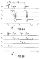
- a known multi heart phase myocardial tagging sequence tsq is shown as a function of the time t.
- TAG a tagging section
- the tagging section is applied under the control of the control unit 8 a predetermined time interval after the control unit receives a trigger pulse tr from the trigger unit 22.
- the tagging section comprises two radio frequency pulses separated by a "wrap" gradient.
- the tagging section may comprise two such rf-pulse gradient combinations in succession.
- the two one dimensional tagging sections must be separated by a socalled spoiler or dephasing gradient, to obtain a multiplication of these two tagging patterns.
- the tagging section TAG is followed by a multi heart phase imaging section after a time interval ⁇ T , the imaging section comprising a number of gradient echo imaging segments temporally spaced over the cardiac cycle.
- Each imaging segment comprises an rf-pulse P1 with excitation angle ⁇ , a slice selection gradient G1, a phase encoding gradient G2 and a readout gradient G3 applied by the rf-coil 13 and the gradient coils 17, 18 and 19, respectively.
- the respective pulse angles can be optimized for particular repetition times and tissue longitudinal relaxation times.
- the sequence tsq is repeated a number of times, e.g. 256, for different values of the phase encoding gradient G2.
- the time interval between the kth and (k+1)th imaging segment is ⁇ k .
- a SPAMM tagging section TAG for applying a grid like tagging pattern comprising first and second radio frequency pulses P2 and P3 separated by a first "wrap" gradient G7, and comprising third and fourth radio frequency pulses P4 and P5 separated by a second "wrap” gradient G6, the first and the second "wrap” gradient being orthogonal with respect to each other.
- the gradients G4 and G5, which must be in slice selection direction, are applied to dephase any x and y components of the tagging magnetization.
- the factors ⁇ and ⁇ are determined by the integrals of the gradients G7 and G6, respectively.
- the amplitudes of the pulses P2, P3, P4 and P5 can be constant.
- the radio frequency pulses P2 and P3, and P4 and P5 form so-called "11" sets of pulses then, the sum of the pulse angles of the pulses P2 and P3, and P3 and P4 being in a range of 90° and 180°.
- Binomial pulse combinations such as "121" or "1331" pulses can also be applied, separated by gradients. Practically the summed angle amounts between 90° and 180°.
- the tagging angle can be optimized to obtain a better contrast than a known SPAMM sequence. For example, when measuring a diastolic, a midstolic, and a systolic modulus image with an excitation angle of 35°, the tagging contrast at the systolic images on the myocardium is maximal, using a tagging angle of about 140°.
- the present invention overcomes such problems. Application of binomial pulse combinations might take too long, i.e. the tagging section might not be completed before the heart begins to move.
- the first term QT0 M0.TAG(x,y).exp(- ⁇ T/T1) represents a decaying image of the object which has been modulated by the tagging pattern
- the second term, QR0 1 - exp(- ⁇ T/T1) represents an image of the object due only to that magnetization that has been relaxed since the application of the tagging section TAG.
- QT k contains the information for monitoring myocardial motion
- the variables x and represent object coordinates at the point in time t t0 at which the tagging section TAG is applied.
- the tagged image is given by ⁇ k.(1 - cos( ⁇ x)).(1 - cos( ⁇ y)) + QR k Basically the tagging grid can be automatically detected by searching for the lines of minima within the tagged image. However due to the presence of the term QR k and the influence of ⁇ k, the actual values of these minima vary widely. In an image with large intensity variations, which is usually the case, it could be very difficult to detect these minima.
- the term QR k is eliminated in order to allow for reliable automatic detection of tagging grids in tagged images.
- the elimination is achieved by performing pairs of measurements with two spatially differing tagging functions and by subtracting the tagged images resulting from two tagging pulse and gradient sequences tsq with different tagging sections TAG incorporating these tagging functions.
- TAG1(x,y) -TAG2(x,y)
- TAG1(x,y) cos( ⁇ x).cos( ⁇ y)
- the form of the tagged image is as follows
- the lines of minima substantially have zero intensity, which make them very easy to detect.
- the zero intensity lines are detected automatically by means of the processing means 9 through scanning of the resulting tagged image.
- the tagging magnetic resonance method according to the present invention gives very sharp minima when the tagging grid is defined as a modulus image.
- the tagging grid lines can be narrowed by applying binomial pulses, with a summed pulse angle of 90° for each tagging direction.
- the form of the tagging function then is, by rough approximation (1 - cos n ( ⁇ x)).(1 - cos n ( ⁇ y)) n being the order of the binomial sequence.
- the duration of the tagging sequence increases with the order n and tagging might not be completed before the heart starts to move. In case of myocardial motion the 180° variant is thus preferred.
Landscapes
- Physics & Mathematics (AREA)
- Health & Medical Sciences (AREA)
- Engineering & Computer Science (AREA)
- Nuclear Medicine, Radiotherapy & Molecular Imaging (AREA)
- High Energy & Nuclear Physics (AREA)
- Physiology (AREA)
- Signal Processing (AREA)
- General Health & Medical Sciences (AREA)
- Radiology & Medical Imaging (AREA)
- Condensed Matter Physics & Semiconductors (AREA)
- General Physics & Mathematics (AREA)
- Life Sciences & Earth Sciences (AREA)
- Biophysics (AREA)
- Vascular Medicine (AREA)
- Cardiology (AREA)
- Power Engineering (AREA)
- Pulmonology (AREA)
- Magnetic Resonance Imaging Apparatus (AREA)
Applications Claiming Priority (2)
| Application Number | Priority Date | Filing Date | Title |
|---|---|---|---|
| EP91200762 | 1991-04-02 | ||
| EP91200762 | 1991-04-02 |
Publications (3)
| Publication Number | Publication Date |
|---|---|
| EP0507392A2 true EP0507392A2 (fr) | 1992-10-07 |
| EP0507392A3 EP0507392A3 (en) | 1993-06-23 |
| EP0507392B1 EP0507392B1 (fr) | 1998-06-10 |
Family
ID=8207583
Family Applications (1)
| Application Number | Title | Priority Date | Filing Date |
|---|---|---|---|
| EP92200885A Expired - Lifetime EP0507392B1 (fr) | 1991-04-02 | 1992-03-30 | Procédé d'imagerie par résonance magnétique et dispositif pour surveiller le mouvement d'une partie d'un objet |
Country Status (4)
| Country | Link |
|---|---|
| US (1) | US5275163A (fr) |
| EP (1) | EP0507392B1 (fr) |
| JP (1) | JP3287416B2 (fr) |
| DE (1) | DE69225832T2 (fr) |
Cited By (2)
| Publication number | Priority date | Publication date | Assignee | Title |
|---|---|---|---|---|
| WO2002023211A1 (fr) * | 2000-09-12 | 2002-03-21 | Koninklijke Philips Electronics N.V. | Procede par resonance magnetique |
| WO2003046599A1 (fr) * | 2001-11-26 | 2003-06-05 | Koninklijke Philips Electronics Nv | Excitations preparatoires multiples et mesures distribuees sur le cycle cardiaque |
Families Citing this family (17)
| Publication number | Priority date | Publication date | Assignee | Title |
|---|---|---|---|---|
| JP3146033B2 (ja) * | 1991-11-05 | 2001-03-12 | 株式会社東芝 | 磁気共鳴イメージング装置 |
| AU7837898A (en) | 1997-06-12 | 1998-12-30 | Johns Hopkins University School Of Medicine, The | Method for measuring myocardial motion and the like |
| US6453187B1 (en) | 1998-08-10 | 2002-09-17 | The Johns Hopkins University | Method of employing angle images for measuring object motion in tagged magnetic resonance imaging |
| US6721589B1 (en) * | 1999-11-30 | 2004-04-13 | General Electric Company | Rapid three-dimensional magnetic resonance tagging for studying material deformation and strain |
| US6597935B2 (en) | 2000-02-10 | 2003-07-22 | The Johns Hopkins University | Method for harmonic phase magnetic resonance imaging |
| EP1334467A2 (fr) * | 2000-10-31 | 2003-08-13 | Koninklijke Philips Electronics N.V. | Procede et systeme permettant la detection et le suivi de marqueurs dans des images a marqueurs irm |
| WO2006119475A2 (fr) * | 2005-05-04 | 2006-11-09 | Johns Hopkins University | Estimation de mouvement de resonance magnetique tridimensionnel sur un plan d'image unique |
| WO2009089341A1 (fr) * | 2008-01-09 | 2009-07-16 | Washington University In St. Louis | Procédé pour mettre en correspondance quantitativement la fonction contractile myocardique avec une analyse des efforts multiparamétrique à base de résonance magnétique |
| US9259290B2 (en) * | 2009-06-08 | 2016-02-16 | MRI Interventions, Inc. | MRI-guided surgical systems with proximity alerts |
| CN102625670B (zh) | 2009-06-16 | 2015-07-15 | 核磁共振成像介入技术有限公司 | Mri导向装置以及能够近实时地跟踪和生成该装置的动态可视化的mri导向的介入系统 |
| WO2013040546A1 (fr) * | 2011-09-16 | 2013-03-21 | University Of Pittsburgh - Of The Commonwealth | Mesure électrophysiologique sans contact et imagerie du cœur |
| IN2013CH05587A (fr) | 2013-12-04 | 2015-06-12 | Gen Electric | |
| WO2015084446A1 (fr) * | 2013-12-04 | 2015-06-11 | General Electric Company | Détection de mouvement dans des images médicales dynamiques |
| WO2016081677A1 (fr) * | 2014-11-19 | 2016-05-26 | The Johns Hopkins University | Schéma d'imagerie et de marquage pulsé stationnaire pour perfusion non invasive |
| CN105701846B (zh) * | 2014-11-27 | 2019-01-15 | 东芝医疗系统株式会社 | 医学图像处理装置和方法以及医学成像设备 |
| DE102015206874B4 (de) * | 2015-04-16 | 2017-04-13 | Siemens Healthcare Gmbh | Zeitaufgelöste MR-Abbildungen bei zyklischer Bewegung |
| JP7233902B2 (ja) * | 2018-11-30 | 2023-03-07 | 慶應義塾 | 磁気共鳴イメージング方法及び磁気共鳴イメージング装置 |
Citations (5)
| Publication number | Priority date | Publication date | Assignee | Title |
|---|---|---|---|---|
| EP0205136A2 (fr) * | 1985-06-14 | 1986-12-17 | General Electric Company | Appareil et procédé de mesure et de représentation d'un flux liquide |
| DE3918625A1 (de) * | 1988-06-07 | 1989-12-14 | Hitachi Ltd | Verfahren und vorrichtung zur kinematographischen magnetresonanz-(mr)-abbildung |
| US4953554A (en) * | 1988-03-04 | 1990-09-04 | Resonex, Inc. | Magnetic resonance imaging method |
| US5054489A (en) * | 1988-10-06 | 1991-10-08 | The Trustees Of The University Of Pennsylvania | Magnetic resonance imaging using spatial modulation of magnetization |
| WO1992003089A1 (fr) * | 1990-08-17 | 1992-03-05 | The Trustees Of The University Of Pennsylvania | Analyse des mouvements de la paroi du c×ur par modulation spatiale de magnetisation |
-
1992
- 1992-03-30 DE DE69225832T patent/DE69225832T2/de not_active Expired - Fee Related
- 1992-03-30 EP EP92200885A patent/EP0507392B1/fr not_active Expired - Lifetime
- 1992-03-30 US US07/859,749 patent/US5275163A/en not_active Expired - Lifetime
- 1992-04-02 JP JP08102892A patent/JP3287416B2/ja not_active Expired - Fee Related
Patent Citations (5)
| Publication number | Priority date | Publication date | Assignee | Title |
|---|---|---|---|---|
| EP0205136A2 (fr) * | 1985-06-14 | 1986-12-17 | General Electric Company | Appareil et procédé de mesure et de représentation d'un flux liquide |
| US4953554A (en) * | 1988-03-04 | 1990-09-04 | Resonex, Inc. | Magnetic resonance imaging method |
| DE3918625A1 (de) * | 1988-06-07 | 1989-12-14 | Hitachi Ltd | Verfahren und vorrichtung zur kinematographischen magnetresonanz-(mr)-abbildung |
| US5054489A (en) * | 1988-10-06 | 1991-10-08 | The Trustees Of The University Of Pennsylvania | Magnetic resonance imaging using spatial modulation of magnetization |
| WO1992003089A1 (fr) * | 1990-08-17 | 1992-03-05 | The Trustees Of The University Of Pennsylvania | Analyse des mouvements de la paroi du c×ur par modulation spatiale de magnetisation |
Non-Patent Citations (3)
| Title |
|---|
| MAGNETIC RESONANCE IN MEDICINE. vol. 15, no. 2, 1 August 1990, DULUTH,MN US pages 334 - 339 T.J. MOSHER ET AL. 'A DANTE Tagging Sequence for the Evaluation of Translational Sample Motion' * |
| RADIOLOGY vol. 169, no. 1, 1 October 1988, NEW YORK, US pages 59 - 63 E.A. ZERHOUNI ET AL. 'Human Heart: Tagging with MR Imaging - A Method for Noninvasive Assessment of Myocardial Motion' * |
| RADIOLOGY vol. 171, no. 3, 1 June 1989, NEW YORK, US pages 841 - 845 L. AXEL ET AL. 'MR Imaging of Motion with Spatial Modulation of Magnetization' * |
Cited By (4)
| Publication number | Priority date | Publication date | Assignee | Title |
|---|---|---|---|---|
| WO2002023211A1 (fr) * | 2000-09-12 | 2002-03-21 | Koninklijke Philips Electronics N.V. | Procede par resonance magnetique |
| US6694166B2 (en) | 2000-09-12 | 2004-02-17 | Koninklijke Philips Electronics N.V. | Magnetic resonance method |
| WO2003046599A1 (fr) * | 2001-11-26 | 2003-06-05 | Koninklijke Philips Electronics Nv | Excitations preparatoires multiples et mesures distribuees sur le cycle cardiaque |
| US7047060B1 (en) | 2001-11-26 | 2006-05-16 | Koninklijke Philips Electronics N.V. | Multiple preparatory excitations and readouts distributed over the cardiac cycle |
Also Published As
| Publication number | Publication date |
|---|---|
| US5275163A (en) | 1994-01-04 |
| EP0507392A3 (en) | 1993-06-23 |
| JPH05115458A (ja) | 1993-05-14 |
| EP0507392B1 (fr) | 1998-06-10 |
| DE69225832D1 (de) | 1998-07-16 |
| JP3287416B2 (ja) | 2002-06-04 |
| DE69225832T2 (de) | 1998-12-24 |
Similar Documents
| Publication | Publication Date | Title |
|---|---|---|
| EP0507392B1 (fr) | Procédé d'imagerie par résonance magnétique et dispositif pour surveiller le mouvement d'une partie d'un objet | |
| US5711300A (en) | Real time in vivo measurement of temperature changes with NMR imaging | |
| EP0543468B1 (fr) | Procédé de résonance magnétique | |
| US4973906A (en) | Flow compensated NMR fast pulse sequence | |
| US5168226A (en) | Acquisition of multiple images in fast spin echo nmr scans | |
| US5151656A (en) | Correction of nmr data acquired by an echo-planar technique | |
| EP0445151B1 (fr) | Artefacts de reduction de mouvement dans des images de resonance magnetique nucleaire (nmr) | |
| US4843322A (en) | Method for producing multi-slice NMR images | |
| US4521733A (en) | NMR Imaging of the transverse relaxation time using multiple spin echo sequences | |
| US5256967A (en) | Fast NMR image acquisition with spectrally selective inversion pulses | |
| US5226418A (en) | Phase correction of complex - difference processed magnetic resonance angiograms | |
| US5347216A (en) | Fast NMR image acquisition with spectrally selective inversion pulse | |
| US5339035A (en) | MR imaging with rectangular magnetization transfer pulse | |
| EP0582967A1 (fr) | Angiographie RMN utilisant des séquences d'impulsions rapides avec des impulsions de préparation | |
| US5379766A (en) | Magnetic resonance imaging method and device for monitoring motion of a part of an object based on stimulated echoes | |
| US5170122A (en) | NMR imaging using flow compensated SSFP pulse sequences | |
| US6265873B1 (en) | Non-CPMG fast spin echo MRI method | |
| CN103477239B (zh) | 使用apt/cest的运动触发的mr成像 | |
| US10156625B2 (en) | MR imaging with B1 mapping | |
| US4968935A (en) | Selective rephasing of NMR signals to suppress motion artifacts | |
| US4803432A (en) | Short echo NMR imaging of sodium | |
| US5101156A (en) | Rapid flow measurement using an nmr imaging system | |
| US5185574A (en) | NMR measurements using recursive RF excitation | |
| US4777439A (en) | Spatially localized spectroscopy | |
| US5291891A (en) | Monitoring body functions using fast NMR pulse sequences |
Legal Events
| Date | Code | Title | Description |
|---|---|---|---|
| PUAI | Public reference made under article 153(3) epc to a published international application that has entered the european phase |
Free format text: ORIGINAL CODE: 0009012 |
|
| AK | Designated contracting states |
Kind code of ref document: A2 Designated state(s): DE FR GB NL |
|
| PUAL | Search report despatched |
Free format text: ORIGINAL CODE: 0009013 |
|
| AK | Designated contracting states |
Kind code of ref document: A3 Designated state(s): DE FR GB NL |
|
| 17P | Request for examination filed |
Effective date: 19931213 |
|
| GRAG | Despatch of communication of intention to grant |
Free format text: ORIGINAL CODE: EPIDOS AGRA |
|
| 17Q | First examination report despatched |
Effective date: 19970731 |
|
| GRAG | Despatch of communication of intention to grant |
Free format text: ORIGINAL CODE: EPIDOS AGRA |
|
| GRAH | Despatch of communication of intention to grant a patent |
Free format text: ORIGINAL CODE: EPIDOS IGRA |
|
| GRAH | Despatch of communication of intention to grant a patent |
Free format text: ORIGINAL CODE: EPIDOS IGRA |
|
| GRAA | (expected) grant |
Free format text: ORIGINAL CODE: 0009210 |
|
| AK | Designated contracting states |
Kind code of ref document: B1 Designated state(s): DE FR GB NL |
|
| PG25 | Lapsed in a contracting state [announced via postgrant information from national office to epo] |
Ref country code: NL Free format text: LAPSE BECAUSE OF FAILURE TO SUBMIT A TRANSLATION OF THE DESCRIPTION OR TO PAY THE FEE WITHIN THE PRESCRIBED TIME-LIMIT Effective date: 19980610 |
|
| REF | Corresponds to: |
Ref document number: 69225832 Country of ref document: DE Date of ref document: 19980716 |
|
| RAP4 | Party data changed (patent owner data changed or rights of a patent transferred) |
Owner name: KONINKLIJKE PHILIPS ELECTRONICS N.V. |
|
| ET | Fr: translation filed | ||
| NLV1 | Nl: lapsed or annulled due to failure to fulfill the requirements of art. 29p and 29m of the patents act | ||
| PLBE | No opposition filed within time limit |
Free format text: ORIGINAL CODE: 0009261 |
|
| STAA | Information on the status of an ep patent application or granted ep patent |
Free format text: STATUS: NO OPPOSITION FILED WITHIN TIME LIMIT |
|
| 26N | No opposition filed | ||
| REG | Reference to a national code |
Ref country code: GB Ref legal event code: IF02 |
|
| REG | Reference to a national code |
Ref country code: FR Ref legal event code: D6 |
|
| REG | Reference to a national code |
Ref country code: GB Ref legal event code: 746 Effective date: 20021017 |
|
| PGFP | Annual fee paid to national office [announced via postgrant information from national office to epo] |
Ref country code: GB Payment date: 20090331 Year of fee payment: 18 |
|
| PGFP | Annual fee paid to national office [announced via postgrant information from national office to epo] |
Ref country code: DE Payment date: 20090512 Year of fee payment: 18 Ref country code: FR Payment date: 20090330 Year of fee payment: 18 |
|
| GBPC | Gb: european patent ceased through non-payment of renewal fee |
Effective date: 20100330 |
|
| REG | Reference to a national code |
Ref country code: FR Ref legal event code: ST Effective date: 20101130 |
|
| PG25 | Lapsed in a contracting state [announced via postgrant information from national office to epo] |
Ref country code: FR Free format text: LAPSE BECAUSE OF NON-PAYMENT OF DUE FEES Effective date: 20100331 |
|
| PG25 | Lapsed in a contracting state [announced via postgrant information from national office to epo] |
Ref country code: DE Free format text: LAPSE BECAUSE OF NON-PAYMENT OF DUE FEES Effective date: 20101001 |
|
| PG25 | Lapsed in a contracting state [announced via postgrant information from national office to epo] |
Ref country code: GB Free format text: LAPSE BECAUSE OF NON-PAYMENT OF DUE FEES Effective date: 20100330 |