EP0507101B1 - Flow amount measuring and controlling apparatus - Google Patents
Flow amount measuring and controlling apparatus Download PDFInfo
- Publication number
- EP0507101B1 EP0507101B1 EP92103830A EP92103830A EP0507101B1 EP 0507101 B1 EP0507101 B1 EP 0507101B1 EP 92103830 A EP92103830 A EP 92103830A EP 92103830 A EP92103830 A EP 92103830A EP 0507101 B1 EP0507101 B1 EP 0507101B1
- Authority
- EP
- European Patent Office
- Prior art keywords
- flow amount
- change
- appliance
- computing
- momentary
- Prior art date
- Legal status (The legal status is an assumption and is not a legal conclusion. Google has not performed a legal analysis and makes no representation as to the accuracy of the status listed.)
- Expired - Lifetime
Links
Images



Classifications
-
- G—PHYSICS
- G01—MEASURING; TESTING
- G01F—MEASURING VOLUME, VOLUME FLOW, MASS FLOW OR LIQUID LEVEL; METERING BY VOLUME
- G01F15/00—Details of, or accessories for, apparatus of groups G01F1/00 - G01F13/00 insofar as such details or appliances are not adapted to particular types of such apparatus
- G01F15/07—Integration to give total flow, e.g. using mechanically-operated integrating mechanism
-
- G—PHYSICS
- G01—MEASURING; TESTING
- G01F—MEASURING VOLUME, VOLUME FLOW, MASS FLOW OR LIQUID LEVEL; METERING BY VOLUME
- G01F15/00—Details of, or accessories for, apparatus of groups G01F1/00 - G01F13/00 insofar as such details or appliances are not adapted to particular types of such apparatus
- G01F15/07—Integration to give total flow, e.g. using mechanically-operated integrating mechanism
- G01F15/075—Integration to give total flow, e.g. using mechanically-operated integrating mechanism using electrically-operated integrating means
- G01F15/0755—Integration to give total flow, e.g. using mechanically-operated integrating mechanism using electrically-operated integrating means involving digital counting
-
- G—PHYSICS
- G01—MEASURING; TESTING
- G01F—MEASURING VOLUME, VOLUME FLOW, MASS FLOW OR LIQUID LEVEL; METERING BY VOLUME
- G01F15/00—Details of, or accessories for, apparatus of groups G01F1/00 - G01F13/00 insofar as such details or appliances are not adapted to particular types of such apparatus
- G01F15/001—Means for regulating or setting the meter for a predetermined quantity
- G01F15/002—Means for regulating or setting the meter for a predetermined quantity for gases
-
- G—PHYSICS
- G01—MEASURING; TESTING
- G01F—MEASURING VOLUME, VOLUME FLOW, MASS FLOW OR LIQUID LEVEL; METERING BY VOLUME
- G01F3/00—Measuring the volume flow of fluids or fluent solid material wherein the fluid passes through the meter in successive and more or less isolated quantities, the meter being driven by the flow
- G01F3/02—Measuring the volume flow of fluids or fluent solid material wherein the fluid passes through the meter in successive and more or less isolated quantities, the meter being driven by the flow with measuring chambers which expand or contract during measurement
- G01F3/20—Measuring the volume flow of fluids or fluent solid material wherein the fluid passes through the meter in successive and more or less isolated quantities, the meter being driven by the flow with measuring chambers which expand or contract during measurement having flexible movable walls, e.g. diaphragms, bellows
- G01F3/22—Measuring the volume flow of fluids or fluent solid material wherein the fluid passes through the meter in successive and more or less isolated quantities, the meter being driven by the flow with measuring chambers which expand or contract during measurement having flexible movable walls, e.g. diaphragms, bellows for gases
Definitions
- the present invention generally relates to a flow amount measuring and controlling apparatus to be included in a gas meter.
- the flow amount of gas is observed so as to estimate from the flow amount change what type of gas appliance is being used, so that the gas is shut off when the gas appliance has been judged to be used in an abnormal way.
- gas meters are recently utilized, which have microcomputers built in, and have a function of shutting off the gas flow when gas appliances are judged to be abnormally used and from the changes in gas flow amount it is judged that raw gas is released.
- Such conventional gas meters with a safety function attached to it detect changes in flow amount of gas passing through the gas meter, so as to recognize whether a gas appliance of a capacity equivalent to the size in change has been ignited or put out.
- the gas supply is adapted to be shut off when the above described gas appliance has been continuously used beyond a maximum time which is previously set in accordance with the capacity of the recognized gas appliance.
- Recent gas appliances have not only two changes of ignition/extinction, but also continuous changes of flow amount during use in accordance with the situation, for example, when a gas fan heater is used to raise the ambient temperature, the combustion amount of the gas fan heater gradually becomes lower as the ambient temperature rises.
- the conventional gas meter with a safety function attached to it recognizes the flow amount changes as the extinction of the above described first gas appliance and the ignition of second gas appliance of smaller capacity.
- a third gas appliance equivalent in capacity to the flow amount increase is recognized to have been ignited.
- a gas hot water feeding apparatus with larger combustion capacity to be set outdoors is used for various applications such as in a bath, shower, dish washing in a kitchen, and so on. It is often used continuously more than one hour. In such a appliance to be set outdoors, the maximum time of continuous use may be desired to be set especially longer, differently from indoor appliance. This kind of use can be settled without problems if the type of the gas appliance in use at the present time can be recognized correctly.
- EP-A-264 856 an apparatus is known, in which the amount of gas consumption, individual maximum flow rate and continuous consumption time of a consumer are measured in a predetermined time period, and a normal reference gas consumption pattern is decided based on the measurement values. Thereafter, a signal outputted from a consumption state detection means is compared with the normal reference gas consumption pattern, and when an abnormal state is detected, a shutoff means is automatically operated by control of a micro-computer.
- the present invention has been developed with a view to substantially eliminating the above discussed drawbacks inherent in the prior art, and a particular object of the present invention is to provide a flow amount measuring apparatus which can recognize which gas appliance now is used by the monitoring operation of the flow amount passing through a gas meter, and can integrate the used flow amount for each appliance.
- a flow amount measuring apparatus which has information stored in advance such as rising flow amount information at the ignition time of various gas appliances, information of the using flow amount capacity of the various types of gas appliances, information as to whether or not the appliance in use changes the flow amount during the operation, besides in the time of ignition/ extinction, information about change of the using flow amount with respect to the time passing from the ignition of the various types of gas appliances, and so on.
- the amount of the gas flow passing through the gas meter changes, comparisons are effected among the respective types of information, actually measured gas flow amount values, changes in the gas flow amount, and time periods required to change. From above information, the gas appliance now ignited/extinguished or increased the flow amount is possibly assumed. And by using the maximum possibility of gas appliance which made gas flow change, the appliance recognition capacity is increased remarkably as compared with the conventional one.
- a gas meter with a safety function attached to it, which is capable of evading the dangerous condition such as gas appliance not to turn off, raw gas releasing and so on by the use of the present invention can be realized.
- the present invention can realize a rate policy for each appliance simply with one gas meter.
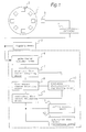
- Fig. 1 is a system block diagram of a flow amount measuring apparatus showing one embodiment of the present invention.
- reference numeral 1 is a disc for effecting one rotation through an interlocking operation with one round trip of the film of a film type gas meter
- reference numeral 2 is a plurality of magnets (which are assumed to be eight in the present embodiment) disposed on the disc 1
- reference numeral 3 is a magnetic resistance element fixedly secured near the disc 1 so as to detect the change in the magnetic field
- reference numeral 4 is a comparator for converting the outputs of the magnetic resistance element 3 into pulses
- reference numeral 5 is an integrating means for counting the pulses from the comparator 4 so as to effect an integrating operation.
- Reference numeral 6 is a pulse interval correcting means for correcting the pulse intervals of the pulse signals from the comparator 4.
- Reference numeral 7 is a momentary flow amount computing means for calculating the flow amount per unit time from the pulse signal and the time width of the pulse signal from the pulse interval correcting means 6.
- Reference numeral 8 is a flow amount change detecting means so as to detect the size of the flow amount change and the continuous time of the flow amount change by the information from the momentary flow amount computing means 7.
- Reference numeral 9 is an individual flow amount estimating means which estimates the gas flow of an appliance which has a gas flow change, by comparing the information from the flow amount change detecting means 8 with characteristic informations of each gas appliance in use that stored in the individual flow amount estimating means 9 itself, and with the gas flow amount information of the gas appliance in use and the household retain which is registered in the appliance characteristic registering means 10.
- Appliance characteristic registering means 10 detects a condition where momentary flow amount does not exist, namely, a condition where no gas appliance is used, and recognizes the ignition of the gas appliance and the maximum rising flow amount at the ignition time by the information from the flow amount change detecting means 8, and then register the maximum ignition flow amount of the ignited gas appliance.
- Reference numeral 11 is a safety control means, which memorizes the maximum time for which each gas appliances can be operated continuously and safely. By the flow amount information of the using gas appliance from the individual estimating means 9, the safety control means 11 judges a case where a certain gas appliance is continuously used beyond the above maximum time is an abnormal use such as the gas appliance not being turned off or the like so as to shut off the gas.
- There is an integrating means for each appliance which integrates and displays the used flow amount for each gas appliance by the information from the individual flow amount estimating means 9.
- the flow amount integrating means for each appliance has a communication means with the outside so as to transmit to the outside the integrating values for each appliance.
- Reference numeral 12 is a flow amount measuring and controlling apparatus of the present invention.
- a film type gas meter is adapted to convert the reciprocating motion in a linear direction of the film by the gas pressure into the rotating motion of the disc.
- the disc 1 does not rotate at a constant angular speed. Therefore, the pulse output from the comparator 4 does not become the pulse output of the equal interval even if magnets 2 are disposed at equal intervals on the disc 1. If the momentary flow amount is calculated under the pulse output, the correct momentary flow amount and the error are caused.
- the pulse interval correcting means 6 is to correct inequality of the above described pulse interval to be caused by the characteristic of the film type gas meter.
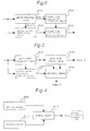
- a block diagram of the pulse interval correcting means 6 is shown for explanation in Fig. 2.
- the pulse signals from the comparator 4 are input to a period detecting means 601 and to a pulse number detecting means 603. Eight pulses are caused respectively for one rotation of the disc 1. Reference pulses are identified from each series of eight pulses which are input in the periodic detecting means 601 so as to transmit the reference pulse information to the pulse number detecting means 603. The pulse which has maximum pulse width of, for example, eight pulses is detected as the reference pulse.
- the correcting coefficient computing means 602 eight signals of one period of series are taken in from the period detecting means 601 so as to measure the respective eight pulse widths for determining the correcting coefficients. The eight correcting coefficients for each eight pulses are transmitted to correcting coefficient storing means.
- One embodiment of the construction of the period detecting means 601 is shown in Fig. 3.
- reference numeral 605 is a pulse width measuring means
- reference numeral 606 is a pulse width storing means
- reference numeral 607 is a steady state condition judging means
- reference numeral 608 is a comparing means.
- the pulse signals from the comparator 4 is measured in the pulse time width by the pulse width measuring means 605.
- the pulse time width of eight pulses for one rotation of the disc 1 is stored in the pulse width storing means 606.
- the steady state condition judging means 607 the meter judges whether the gas is flowing constantly or not. When the gas is flowing constantly, the comparing means 608 is operated.
- the comparing means 608 the eight pulse widths stored in the pulse width storing means 606 are compared with in size so as to take out the maximum pulse width for comparing the pulse width existing at the present time point to be input from the pulse width measuring means 605 with the above described maximum pulse width. If two pulse widths are equal, the pulse input at the present time point is regarded as a reference pulse.
- the output A is caused from the comparing means 608 so that the count value of the pulse number detecting means 603 of Fig. 2 becomes 0.
- Eight pulse width information of one period of pulses stored in the pulse width storing means 606 is output in the order from the reference pulse with respect to the correcting coefficient computing means 602 of Fig. 2.
- Tn is input from the period detecting means 601, and eight pulse widths from TO to T7 are added by the adding means 609.
- the input eight pulse width data are stored in the storing means 610.
- the division between eight pulse widths Tn respectively stored in the storing means 610 and the addition data of the adding means 609 are effected by the dividing means 611 so as to output a correcting coefficient Pn.
- a correcting coefficient Pn in a formula is as follows.
- Pn Tn x 8 / (T0 + T1 + T2 + T3 + T4 + T5 + T6 + T7)
- the correcting coefficient Pn obtained by the above described formula is outputted to the correction coefficient storing means 604 of Fig. 2.
- the pulse number detecting means 603 is composed of a counter circuit for counting the eight pulses. The above described counter circuit is cleared by the signals from the period detecting means 601.
- the reference pulse is a pulse of 0 number.
- the number of the pulse counted from the reference pulse can be known from the pulse to be input at the present time by a pulse number detecting means 603.
- the pulse number detecting means 603 Whenever the pulse is input from the comparator 4, the pulse number detecting means 603 outputs the pulse number of the input pulse to the next stage of correcting coefficient storing means 604.
- the correcting coefficient storing means 604 outputs the correcting coefficient corresponding to the pulse number whenever the pulse number information is input.
- the flow amount measuring apparatus functions automatically to correct the inequality of the pulse signal interval from the comparator 4 which is caused by the characteristics of the film type gas meter, so that correct and highly resolved integration display and.a correct momentary flow amount measuring operation can be realized, with an effect improving safety processing function.
- period detecting means 601 is described in the embodiments of Fig. 2 and Fig. 3 so that it may be operated only at the initial setting time, it may be adapted to operate, reset regularly, for example, once per day.
- the pulse number detecting means 603 outputs the corresponding pulse number each time the pulse inputs, at a time point when the pulse has been input after the lapse of one second after the former pulse number has been output, the collectively input pulse numbers can be output so that the correcting processing operation may be effected in each approximately one second.
- the momentary flow amount Q is equal to 0 when pulses are not input for ten seconds, for example.
- Fig. 5 is a block diagram showing the construction of a flow amount change detecting means 8.
- the gas hot water feeding machine controls the gas combustion amount electronically so that the hot water temperature to be output may be made constant at a set temperature. In such a case, the flow amount changes slowly for a long period of time.
- the flow amount change detecting means 8 detects the pattern of this change so as to detect the length of the continuous change of one gas appliance.
- reference numeral 701 is a storing means for sequentially storing the memory of the flow amount from the momentary flow amount computing means
- reference numeral 702 is a gas flow change judging means which judges whether the gas flow amount change
- Same change judging means 703, judges whether the past flow amount change and the present flow amount change are a series of change of the same gas appliance or the change in the other gas appliance, from the judging result by the above described flow change judging means 702.
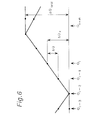
- a conception chart of the same change judging method in the same change judging means 703 is shown in Fig.
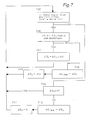
- a flow chart for illustrating the concrete operation of the same change judging means 703 is shown in Fig. 7.
- the operation of the same change judging means 703 will be described hereinafter.
- Qi is a present momentary flow amount
- Qi-1 is a momentary flow amount one before of it.
- Qi-2, Qi-3 are respectively momentary flow amount two, three, before Qi + m is a momentary flow amount value m after from Qi
- ⁇ Q Qi - Qi-i
- ⁇ Qx are present integration values of the same flow amount change
- ⁇ Q total is an overall integration value in the same flow amount change.
- the momentary flow amount value two before and momentary flow amount three before do not change or the flow amount reduces.
- the flow amount increases from the momentary flow amount value two before to the momentary flow amount value m after from Qi.
- the flow amount change is not provided or the flow amount change turns round into decreasing change.
- the same change judging means 703 as shown in Fig.
- the change flow amount ⁇ Q total at a time point when the flow amount has been changed from a condition where the flow amount changes are not effected, or a time point when the flow amount has not been changed from Qi-2 at a time point when the reverse flow amount change has been effected, or to Qi + m at a time point the flow amount has been turned round into inverse flow amount changes are judged as one flow amount change.
- the ⁇ Q total is output as an output C into the next stage of individual flow amount estimating means 9.
- a step 705 it is judged whether the flow amount change signal ⁇ Q exists from the flow change judging means 702. If the flow amount change signal ⁇ Q exists, it is judged whether, in the step 705, ⁇ Q and ⁇ Qx which is integrated value of the same flow amount change, are the same code (the same code in a case of ⁇ Q > 0 and ⁇ Qx >0, or ⁇ Q ⁇ 0 and ⁇ Qx ⁇ 0). If ⁇ Q and ⁇ Qx are the same codes or ⁇ Qx is zero, ⁇ Q is added to ⁇ Qx as the same change in the step 707.
- the reverse changes are caused.
- the ⁇ Q is replaced by ⁇ Q as a new change in the step 708.
- the flow amount change signal ⁇ Q does not exist from the flow change judging means 702 in the step 705
- consectively it is judged whether or not ⁇ Qx is zero in the step 710.
- ⁇ Qx is zero means the flow amount change has not been effected up to the last time. As the flow amount change does not exist this time, the step returns to the step 705 for the next flow amount change judgment without doing anything.
- the signal of the ⁇ Q total is adapted to be output as the output C.
- the operation of the flow amount change continuing time measuring means 704 will be described hereinafter.
- the flow amount change is often slow.
- the gas appliances such as a gas fan heater or the like are extinguished or ignited, the change of falling or rising gas flow amount is steep.
- the time the flow amount change has been continued is measured.
- the start of the flow amount change is detected in the same change judging means 703, a signal informing the start of the flow amount change is transmitted to the flow amount change continuing time measuring means 704.
- the operation of the individual flow amount estimating means 9 will be described hereinafter. With the use of two informations of the size ⁇ Q total from the flow amount change detecting means 8 and the flow amount change continuing time ⁇ T, the gas appliance which the flow amount changes come from is estimated.
- the flow chart for illustrating the operation of the individual flow amount estimating means 9 is shown in Fig. 8.
- the possibility of which gas appliance made gas flow change of ⁇ Q total is computed in the step 901, 902.
- the possibility of gas appliance which increased or decreased gas flow amount is computed and registered to An.
- an additional character n is a register number, which shows an identification number of a gas appliance.
- the possibility of the ignition or the extinction of the gas appliance is computed, and the result is registered to Bn.
- the possibility of the ignition or the extinction of the gas appliance becomes smaller at value, and the possibility of such flow amount increase or decrease as of the hot water feeding machine and so on which have electronic control becomes larger in value.
- the largest value in the register An'and Bn' is selected.
- the gas appliance number n which made the gas flow amount change is possibly assumed. Accordingly, in the case of the example shown in Fig. 6, the possibility of the gentle flow amount change by the proportional control hot water feeding device is calculated to be larger than the possibility of flow amount change by the gas fan heater extinction. As a result, it is estimated that the gas flow amount of the hot water feeding device is decreased.
- Fig. 9 shows a block diagram showing the construction of the individual flow amount estimating means 9.
- Reference numeral 909 is a possibility computing means of gas appliance which made gas flow change of increase or decrease during the use
- reference numeral 910 is a possibility computing means of the ignition of the gas appliance unused and the extinction of the gas appliance during the use
- reference numeral 911 is a possibility correcting means
- reference numeral 912 is an individual flow amount memory storing means for each gas appliances in use
- reference numeral 913 is a comparing means which compares the possibility of the gas appliance which made gas flow change from above mentioned data.
- the possibilities of the flow amount change are computed for each of gas appliances with the use of size of the change flow amount from the flow amount change detecting means 8 of the former stage, the continuous time of the change flow amount, the rising characteristics of the appliance characteristic from the appliance characteristic registering means 10, and the flow amount value to be used at the present time for each of the gas appliances from the individual flow amount storing means 912.
- Such functions as shown in Fig. 10 is used. In (1) and (2) of Fig.
- Fig. 10 Qsn is a gas flow amount at an ignition time of a appliance number n registered in the appliance characteristic registering means 10
- Okn is a flow amount in stable use of gas appliance which stored in the individual flow amount storing means 912
- ⁇ Q is a change flow amount from the flow amount change detecting means 8.
- the function in Fig. 10 can be set under the adjustable gas flow amount value range of the gas appliance.
- Ptum is a function for obtaining the possibility of the ignition
- P1n in (2) is a function for obtaining the possibility of the flow amount change of the gas appliance during the use
- Pman in the (3) is a function for obtaining the possibility of extinction of the appliance in use.
- the flow amount value is considered to change by the pressure variation and so on of the gas piping even if the change is not in the gas appliance.
- the possibility correcting means 911 can compute the possibility of the flow amount change except in the gas appliance.
- the comparing means 913 outputs the information of the gas appliance number n and its flow amount which possibly made largest gas flow change, as the output E.
- a change flow amount ⁇ Q is added to the individual flow amount value of the gas appliance estimated by the comparing means 913 and is stored as the new individual flow value.
- reference numeral 101 is a flow amount zero judging means
- reference numeral 102 is a gate means
- reference numeral 103 is a comparing means
- numeral reference 104 is a memory storing means.
- Signals from the momentary flow amount computing means 7 are input as input A.
- Signals from the flow amount change detecting means 8 are input as input B.
- the flow amount zero judging means 101 judges whether the flow amount is zero or not, namely, a gas appliance is not used or used.
- the flow amount zero judging means 101 is composed so that the output is caused if the gas appliance is not used.
- the flow amount zero judging means 101 outputs a si.gnal as first the gas appliance is not used. When a gas fan heater is used, it is switched to no signal. The switching time to no signal is delayed as compared with the output signal from the flow amount change detecting means 8.
- the gate means 102 transmits the signal of the flow amount change detecting means 8 to the comparing means 103 only when the flow amount zero judging means 101 is outputting a signal.
- the output of the flow amount change detecting means 8 is input to the comparing means 103 through the gate means 102.
- the comparing means 103 signals stored in the memory storing means 104 is compared with signal corresponding to 3000 kcal/h from the flow amount change detecting means 8. Unless the signal corresponding to 3000 kcal/h has been stored in the storing means 104, the output from the comparing means 103 is caused so as to store the signal corresponding to the 3000 kcal/h in the storing means 104.
- the appliance characteristic registering means 10 registers the gas flow amount correspond to gas appliance automatically through the comparing means 103 and the memory storing means 104 only when a certain gas appliance is used from a condition where no other gas appliance is being used, with an effect that the bother of the registration of the new gas appliance is saved.
- a gas appliance can be determined which made the flow amount change by the information such as the gas flow amount rising characteristics and the gas flow amount adjusting range or the like from the individual flow amount estimating means 9.
- the rate policy for each appliance can be effected by the integration of the used gas flow amount for each gas appliance by the integrating means 12 for each gas appliance.
- the flow amount measuring and controlling apparatus of the present invention can be realized easily with the use of the microcomputers.
Landscapes
- Physics & Mathematics (AREA)
- Fluid Mechanics (AREA)
- General Physics & Mathematics (AREA)
- Measuring Volume Flow (AREA)
- Feeding And Controlling Fuel (AREA)
Description
- The present invention generally relates to a flow amount measuring and controlling apparatus to be included in a gas meter. The flow amount of gas is observed so as to estimate from the flow amount change what type of gas appliance is being used, so that the gas is shut off when the gas appliance has been judged to be used in an abnormal way.
- In order to prevent gas explosion accidents, gas meters are recently utilized, which have microcomputers built in, and have a function of shutting off the gas flow when gas appliances are judged to be abnormally used and from the changes in gas flow amount it is judged that raw gas is released. Such conventional gas meters with a safety function attached to it detect changes in flow amount of gas passing through the gas meter, so as to recognize whether a gas appliance of a capacity equivalent to the size in change has been ignited or put out. The gas supply is adapted to be shut off when the above described gas appliance has been continuously used beyond a maximum time which is previously set in accordance with the capacity of the recognized gas appliance.
- But such conventional gas meters with a safety function attached to it have a problem as shown hereinafter. Recent gas appliances have not only two changes of ignition/extinction, but also continuous changes of flow amount during use in accordance with the situation, for example, when a gas fan heater is used to raise the ambient temperature, the combustion amount of the gas fan heater gradually becomes lower as the ambient temperature rises. When the gas flow amount of a first gas appliance has been reduced during the use, the conventional gas meter with a safety function attached to it recognizes the flow amount changes as the extinction of the above described first gas appliance and the ignition of second gas appliance of smaller capacity. When the gas flow amount of the above described first gas appliance has been increased during the use, a third gas appliance equivalent in capacity to the flow amount increase is recognized to have been ignited. As a result, in spite of the fact that a first gas appliance is actually burning large gas flow amounts, the gas meter recognizes that two gas appliances, the second and third gas appliances of smaller capacity, are being used. The maximum time for continuous use of the first gas appliance is extended, with problems that the dangers in gas appliance, forgetting to turn off and raw gas releasing, cannot be prevented. A gas hot water feeding apparatus with larger combustion capacity to be set outdoors is used for various applications such as in a bath, shower, dish washing in a kitchen, and so on. It is often used continuously more than one hour. In such a appliance to be set outdoors, the maximum time of continuous use may be desired to be set especially longer, differently from indoor appliance. This kind of use can be settled without problems if the type of the gas appliance in use at the present time can be recognized correctly.
- The power demand is nowadays increased at summer time by the spread of air conditioners using electric power, this results in insufficient power supply capacity. On the other hand, the gas demand is likely to be reduced at summer time. Therefore, there is a tendency of easing the power demand by the use of air conditioners using gas, and at the same time, of averaging the demand of the gas annually. Thus, a rate policy which makes the gas rate lower in accordance with the gas amount used for air conditioners is considered. In order to effect such a rate policy for each appliance, an auxiliary gas meter for measuring the flow amount of gas air-conditioners is necessary in addition to a main gas meter. Expenditures for an auxiliary gas meter and for installing an auxiliary gas meter onto the gas piping are required. If the types of gas appliances now in use with the main gas meter can be correctly recognized and the used gas amount can be correctly integrated, a rate policy for each appliance can be realized only by the main gas meter.
- From EP-A-264 856 an apparatus is known, in which the amount of gas consumption, individual maximum flow rate and continuous consumption time of a consumer are measured in a predetermined time period, and a normal reference gas consumption pattern is decided based on the measurement values. Thereafter, a signal outputted from a consumption state detection means is compared with the normal reference gas consumption pattern, and when an abnormal state is detected, a shutoff means is automatically operated by control of a micro-computer.
- From GB-A-2 176 643 an apparatus is known, in which the continuous consumption time of a gas appliance in use is measured, and when the measured time value exceeds a continuous service safety time previously memorized, an emergency shut-off valve is operated to cut off the gas supply.
- Accordingly, the present invention has been developed with a view to substantially eliminating the above discussed drawbacks inherent in the prior art, and a particular object of the present invention is to provide a flow amount measuring apparatus which can recognize which gas appliance now is used by the monitoring operation of the flow amount passing through a gas meter, and can integrate the used flow amount for each appliance.
- This object is being solved by an apparatus as defined in
claim 1. Preferred embodiments are defined in the dependent claims. - Particularly, there is provided a flow amount measuring apparatus which has information stored in advance such as rising flow amount information at the ignition time of various gas appliances, information of the using flow amount capacity of the various types of gas appliances, information as to whether or not the appliance in use changes the flow amount during the operation, besides in the time of ignition/ extinction, information about change of the using flow amount with respect to the time passing from the ignition of the various types of gas appliances, and so on. When the amount of the gas flow passing through the gas meter changes, comparisons are effected among the respective types of information, actually measured gas flow amount values, changes in the gas flow amount, and time periods required to change. From above information, the gas appliance now ignited/extinguished or increased the flow amount is possibly assumed. And by using the maximum possibility of gas appliance which made gas flow change, the appliance recognition capacity is increased remarkably as compared with the conventional one.
- In the present invention, as the above described, respective types of information stored in advance is automatically learned by changes in the gas flow amount passing through the gas meter, all the respective types of information is not required to be input by an operator. Therefore, the bother at the gas meter installation time can be saved.
- A gas meter, with a safety function attached to it, which is capable of evading the dangerous condition such as gas appliance not to turn off, raw gas releasing and so on by the use of the present invention can be realized.
- The present invention can realize a rate policy for each appliance simply with one gas meter.
- Fig. 1
- is a system block diagram of a flow amount measuring apparatus showing one embodiment of the present invention;
- Fig. 2, Fig. 3 and Fig. 4
- are block diagrams of pulse interval correcting means which are elements constituting a flow amount measuring apparatus of the present invention;
- Fig. 5
- is a block diagram of flow amount change detecting means which are the other elements constituting a flow amount measuring apparatus of the present invention;
- Fig. 6
- is a flow amount change diagram for illustrating the operation of the above described flow amount change detecting means;
- Fig. 7
- is a flow chart for illustrating the above described flow amount change detecting means;
- Fig. 8
- is a block diagram of an individual flow amount estimating means;
- Fig. 9
- is a flow chart showing the operation of the above described individual flow amount estimating means; and
- Fig. 10
- is a block diagram of an appliance characteristic registering means which are the other elements constituting a flow amount measuring apparatus of the present invention.
- Fig. 1 is a system block diagram of a flow amount measuring apparatus showing one embodiment of the present invention. In the drawing,
reference numeral 1 is a disc for effecting one rotation through an interlocking operation with one round trip of the film of a film type gas meter,reference numeral 2 is a plurality of magnets (which are assumed to be eight in the present embodiment) disposed on thedisc 1,reference numeral 3 is a magnetic resistance element fixedly secured near thedisc 1 so as to detect the change in the magnetic field,reference numeral 4 is a comparator for converting the outputs of themagnetic resistance element 3 into pulses, reference numeral 5 is an integrating means for counting the pulses from thecomparator 4 so as to effect an integrating operation. -
Reference numeral 6 is a pulse interval correcting means for correcting the pulse intervals of the pulse signals from thecomparator 4.Reference numeral 7 is a momentary flow amount computing means for calculating the flow amount per unit time from the pulse signal and the time width of the pulse signal from the pulse interval correcting means 6.Reference numeral 8 is a flow amount change detecting means so as to detect the size of the flow amount change and the continuous time of the flow amount change by the information from the momentary flow amount computing means 7. Reference numeral 9 is an individual flow amount estimating means which estimates the gas flow of an appliance which has a gas flow change, by comparing the information from the flow amount change detecting means 8 with characteristic informations of each gas appliance in use that stored in the individual flow amount estimating means 9 itself, and with the gas flow amount information of the gas appliance in use and the household retain which is registered in the appliance characteristic registering means 10. Appliance characteristic registering means 10 detects a condition where momentary flow amount does not exist, namely, a condition where no gas appliance is used, and recognizes the ignition of the gas appliance and the maximum rising flow amount at the ignition time by the information from the flow amount change detecting means 8, and then register the maximum ignition flow amount of the ignited gas appliance.Reference numeral 11 is a safety control means, which memorizes the maximum time for which each gas appliances can be operated continuously and safely. By the flow amount information of the using gas appliance from the individual estimating means 9, the safety control means 11 judges a case where a certain gas appliance is continuously used beyond the above maximum time is an abnormal use such as the gas appliance not being turned off or the like so as to shut off the gas. There is an integrating means for each appliance, which integrates and displays the used flow amount for each gas appliance by the information from the individual flow amount estimating means 9. The flow amount integrating means for each appliance has a communication means with the outside so as to transmit to the outside the integrating values for each appliance.Reference numeral 12 is a flow amount measuring and controlling apparatus of the present invention. - Although one embodiment of the present invention has been described in outlook, it will be described hereinafter in detail for each block diagram for constituting the present invention.
- A film type gas meter is adapted to convert the reciprocating motion in a linear direction of the film by the gas pressure into the rotating motion of the disc. As its characteristic, even if a gas flow is constant, the
disc 1 does not rotate at a constant angular speed. Therefore, the pulse output from thecomparator 4 does not become the pulse output of the equal interval even ifmagnets 2 are disposed at equal intervals on thedisc 1. If the momentary flow amount is calculated under the pulse output, the correct momentary flow amount and the error are caused. The pulseinterval correcting means 6 is to correct inequality of the above described pulse interval to be caused by the characteristic of the film type gas meter. A block diagram of the pulseinterval correcting means 6 is shown for explanation in Fig. 2. The pulse signals from thecomparator 4 are input to aperiod detecting means 601 and to a pulsenumber detecting means 603. Eight pulses are caused respectively for one rotation of thedisc 1. Reference pulses are identified from each series of eight pulses which are input in the periodic detecting means 601 so as to transmit the reference pulse information to the pulsenumber detecting means 603. The pulse which has maximum pulse width of, for example, eight pulses is detected as the reference pulse. In the correcting coefficient computing means 602, eight signals of one period of series are taken in from the period detecting means 601 so as to measure the respective eight pulse widths for determining the correcting coefficients. The eight correcting coefficients for each eight pulses are transmitted to correcting coefficient storing means. One embodiment of the construction of theperiod detecting means 601 is shown in Fig. 3. In the same drawing,reference numeral 605 is a pulse width measuring means,reference numeral 606 is a pulse width storing means,reference numeral 607 is a steady state condition judging means andreference numeral 608 is a comparing means. The pulse signals from thecomparator 4 is measured in the pulse time width by the pulse width measuring means 605. The pulse time width of eight pulses for one rotation of thedisc 1 is stored in the pulse width storing means 606. In the steady state condition judging means 607, the meter judges whether the gas is flowing constantly or not. When the gas is flowing constantly, the comparing means 608 is operated. In the judgment whether or not the gas is flowing constantly, for example, one signal is output for each divided eight pulses, and if the periods of the above signals are constant, it can be judged that the gas is flowed constantly. Also, in the other method, it can be judged that gas flows constantly if the pulse widths on every eight pulse are equal. In the comparing means 608, the eight pulse widths stored in the pulse width storing means 606 are compared with in size so as to take out the maximum pulse width for comparing the pulse width existing at the present time point to be input from the pulse width measuring means 605 with the above described maximum pulse width. If two pulse widths are equal, the pulse input at the present time point is regarded as a reference pulse. When the reference pulse is input, the output A is caused from the comparing means 608 so that the count value of the pulse number detecting means 603 of Fig. 2 becomes 0. Eight pulse width information of one period of pulses stored in the pulse width storing means 606 is output in the order from the reference pulse with respect to the correcting coefficient computing means 602 of Fig. 2. - One embodiment of the construction for the correcting coefficient computing means 602 will be described with reference to Fig. 4. A correcting coefficient computing method will be described hereinafter.
- Assume that the correcting coefficients and pulse widths of the eight pulses are respectively Pn, Tn (n = 0 through 7), counting from the reference pulses. Tn is input from the
period detecting means 601, and eight pulse widths from TO to T7 are added by the adding means 609. On the other hand, the input eight pulse width data are stored in the storing means 610. The division between eight pulse widths Tn respectively stored in the storing means 610 and the addition data of the adding means 609 are effected by the dividing means 611 so as to output a correcting coefficient Pn. - A correcting coefficient Pn in a formula is as follows.
- The correcting coefficient Pn obtained by the above described formula is outputted to the correction coefficient storing means 604 of Fig. 2. Whether the set values of the reference pulse and the correction coefficient (not shown in Fig. 1 and Fig. 2) are output to the pulse number detecting means 603 and the correcting coefficient storing means 604 is adapted to be controlled from the outside so as to output the set value if necessary, for example, at the initial setting time when the gas meter starts to be used, it is effected with respect to the pulse number detecting means 603 and the correction coefficient storing means 604. In Fig. 2, the pulse number detecting means 603 is composed of a counter circuit for counting the eight pulses. The above described counter circuit is cleared by the signals from the
period detecting means 601. Accordingly, the count value of the pulse number detecting means 603 is 0 at a data time point when the reference pulse has been input. Whenever a pulse is input, the count value is added one by one. The count value restores to 0 when the pulses is input to the next of 7. Namely, whenever the pulse is input, the count value changes as follows. - Accordingly, the reference pulse is a pulse of 0 number. The number of the pulse counted from the reference pulse can be known from the pulse to be input at the present time by a pulse
number detecting means 603. Whenever the pulse is input from thecomparator 4, the pulse number detecting means 603 outputs the pulse number of the input pulse to the next stage of correcting coefficient storing means 604. The correcting coefficient storing means 604 outputs the correcting coefficient corresponding to the pulse number whenever the pulse number information is input. - In the above described construction, the flow amount measuring apparatus functions automatically to correct the inequality of the pulse signal interval from the
comparator 4 which is caused by the characteristics of the film type gas meter, so that correct and highly resolved integration display and.a correct momentary flow amount measuring operation can be realized, with an effect improving safety processing function. - Although the
period detecting means 601 is described in the embodiments of Fig. 2 and Fig. 3 so that it may be operated only at the initial setting time, it may be adapted to operate, reset regularly, for example, once per day. - In the present embodiment, although the pulse number detecting means 603 outputs the corresponding pulse number each time the pulse inputs, at a time point when the pulse has been input after the lapse of one second after the former pulse number has been output, the collectively input pulse numbers can be output so that the correcting processing operation may be effected in each approximately one second.
- Operation of the momentary flow amount computing means 7 in Fig. 1 will be described hereinafter. One second after from inputting the
pulse 0 signal from the pulseinterval correcting means 6, the time and the pulse number betweenpulse 0 and pulse N are measured hereinafter. Momentary flow amount Q is obtained by Q = N/T, here, N is the pulse number and T is the time betweenpulse 0 and pulse N. The momentary flow amount Q is equal to 0 when pulses are not input for ten seconds, for example. - The operation of the flow amount
change detecting means 8 in Fig. 1 will be described hereinafter. Fig. 5 is a block diagram showing the construction of a flow amountchange detecting means 8. Generally the flow amount change at the ignition time of the gas appliance and the flow amount change at extinction time are changed momentarily. The gas hot water feeding machine controls the gas combustion amount electronically so that the hot water temperature to be output may be made constant at a set temperature. In such a case, the flow amount changes slowly for a long period of time. The flow amountchange detecting means 8 detects the pattern of this change so as to detect the length of the continuous change of one gas appliance. In Fig. 5,reference numeral 701 is a storing means for sequentially storing the memory of the flow amount from the momentary flow amount computing means 7,reference numeral 702 is a gas flow change judging means which judges whether the gas flow amount change | Qi-Qi-1 | is more than a previously fixed threshold value, for example, 0,03 XQi, here Qi is a present momentary flow amount and Qi-1 is last value of it. Same change judging means 703, judges whether the past flow amount change and the present flow amount change are a series of change of the same gas appliance or the change in the other gas appliance, from the judging result by the above described flow change judging means 702. A conception chart of the same change judging method in the same change judging means 703 is shown in Fig. 6, a flow chart for illustrating the concrete operation of the same change judging means 703 is shown in Fig. 7. The operation of the same change judging means 703 will be described hereinafter. In Fig. 6, Qi is a present momentary flow amount, Qi-1 is a momentary flow amount one before of it. Qi-2, Qi-3 are respectively momentary flow amount two, three, before Qi + m is a momentary flow amount value m after from Qi, ΔQ = Qi - Qi-i, ΔQx are present integration values of the same flow amount change, ΔQtotal is an overall integration value in the same flow amount change. - In the example of Fig. 6, the momentary flow amount value two before and momentary flow amount three before do not change or the flow amount reduces. The flow amount increases from the momentary flow amount value two before to the momentary flow amount value m after from Qi. At the time of m number and its subsequent, the flow amount change is not provided or the flow amount change turns round into decreasing change. In the same change judging means 703, as shown in Fig. 6, the change flow amount ΔQtotal at a time point when the flow amount has been changed from a condition where the flow amount changes are not effected, or a time point when the flow amount has not been changed from Qi-2 at a time point when the reverse flow amount change has been effected, or to Qi + m at a time point the flow amount has been turned round into inverse flow amount changes are judged as one flow amount change. The ΔQtotal is output as an output C into the next stage of individual flow amount estimating means 9.
- The detailed operation of the above described same change judging means 703 will be described hereinafter in accordance with the flow chart of Fig. 7. At a
step 705, it is judged whether the flow amount change signal ΔQ exists from the flow change judging means 702. If the flow amount change signal ΔQ exists, it is judged whether, in thestep 705, ΔQ and ΔQx which is integrated value of the same flow amount change, are the same code (the same code in a case of ΔQ > 0 and ΔQx >0, or ΔQ < 0 and ΔQx < 0). If ΔQ and ΔQx are the same codes or ΔQx is zero, ΔQ is added to ΔQx as the same change in thestep 707. If the ΔQ and ΔQx are not the same codes, the reverse changes are caused. After the ΔQtotal has been replaced by the ΔQx in thestep 709, the ΔQ is replaced by ΔQ as a new change in thestep 708. If it is judged that the flow amount change signal ΔQ does not exist from the flow change judging means 702 in thestep 705, consectively it is judged whether or not ΔQx is zero in thestep 710. ΔQx is zero means the flow amount change has not been effected up to the last time. As the flow amount change does not exist this time, the step returns to thestep 705 for the next flow amount change judgment without doing anything. If there is no signal from flow change judging means 702 and ΔQx is not zero at thestep 710, it means last series of change was completed, and the ΔQx is substituted by zero at thestep 711 after the ΔQtotal has been replaced by the ΔQx in thestep 12. In thestep 709 and thestep 712, the signal of the ΔQtotal is adapted to be output as the output C. - The operation of the flow amount change continuing time measuring means 704 will be described hereinafter. As described hereinabove, when the gas hot water feeding apparatus changes the momentary gas flow amount by the electronic control, the flow amount change is often slow. When the gas appliances such as a gas fan heater or the like are extinguished or ignited, the change of falling or rising gas flow amount is steep. In order to find out the gas appliance correctly which made gas flow amount change using the characteristics of gas flow amount change, the time the flow amount change has been continued is measured. When the start of the flow amount change is detected in the same change judging means 703, a signal informing the start of the flow amount change is transmitted to the flow amount change continuing time measuring means 704. When it is confirmed that the flow amount change has been completed from the same change judging means 703, a signal informing the flow amount change completion is transmitted to the flow amount change continuing time measuring means 704. The time from the start to the completion of the flow amount change is measured as ΔT so as to output as the output D to the next stage of individual flow amount estimating means 9.
- The operation of the individual flow amount estimating means 9 will be described hereinafter. With the use of two informations of the size ΔQtotal from the flow amount
change detecting means 8 and the flow amount change continuing time ΔT, the gas appliance which the flow amount changes come from is estimated. The flow chart for illustrating the operation of the individual flow amount estimating means 9 is shown in Fig. 8. The possibility of which gas appliance made gas flow change of ΔQtotal is computed in thestep step 901, the possibility of gas appliance which increased or decreased gas flow amount is computed and registered to An. Here an additional character n is a register number, which shows an identification number of a gas appliance. In thestep 902, the possibility of the ignition or the extinction of the gas appliance is computed, and the result is registered to Bn. In thestep 903, it is judged whether the flow amount change is gentle or steep with the use of the flow amount change continuing time ΔT. If the change is gentle, in thestep 904, coefficients K1 = 1, K2 = x (previously determined constant of x < 1). If the change is steep in thestep 903, coefficients K1 = x, K2 = 1 are established in thestep 905. In thestep 906, the possibility of flow amount change of the respective gas appliances computed in thestep 901 and step 902 are corrected by the coefficients K1, K2. Namely, the possibility An is multiplied by the coefficient K1 and registered to An'. The possibility Bn is multiplied by the coefficient K2 and registered to Bn'. When the flow amount change is gentle by the operation, the possibility of the ignition or the extinction of the gas appliance becomes smaller at value, and the possibility of such flow amount increase or decrease as of the hot water feeding machine and so on which have electronic control becomes larger in value. In thestep 907, the largest value in the register An'and Bn' is selected. In thestep 908, the gas appliance number n which made the gas flow amount change is possibly assumed. Accordingly, in the case of the example shown in Fig. 6, the possibility of the gentle flow amount change by the proportional control hot water feeding device is calculated to be larger than the possibility of flow amount change by the gas fan heater extinction. As a result, it is estimated that the gas flow amount of the hot water feeding device is decreased. - Fig. 9 shows a block diagram showing the construction of the individual flow amount estimating means 9.
Reference numeral 909 is a possibility computing means of gas appliance which made gas flow change of increase or decrease during the use,reference numeral 910 is a possibility computing means of the ignition of the gas appliance unused and the extinction of the gas appliance during the use,reference numeral 911 is a possibility correcting means,reference numeral 912 is an individual flow amount memory storing means for each gas appliances in use,reference numeral 913 is a comparing means which compares the possibility of the gas appliance which made gas flow change from above mentioned data. In the various types of possibility computing means of thereference numerals change detecting means 8 of the former stage, the continuous time of the change flow amount, the rising characteristics of the appliance characteristic from the appliance characteristic registering means 10, and the flow amount value to be used at the present time for each of the gas appliances from the individual flow amount storing means 912. For the computing method of the possibility, such functions as shown in Fig. 10 is used. In (1) and (2) of Fig. 10, Qsn is a gas flow amount at an ignition time of a appliance number n registered in the appliance characteristic registering means 10, Okn is a flow amount in stable use of gas appliance which stored in the individual flow amount storing means 912, ΔQ is a change flow amount from the flow amountchange detecting means 8. The function in Fig. 10 can be set under the adjustable gas flow amount value range of the gas appliance. In (1) of Fig. 10, Ptum is a function for obtaining the possibility of the ignition, P1n in (2) is a function for obtaining the possibility of the flow amount change of the gas appliance during the use, Pman in the (3) is a function for obtaining the possibility of extinction of the appliance in use. The value of the possibility obtained from each function of Fig. 10 is corrected by the way described in the flow chart of Fig. 8 using the information from the flow amountchange detecting means 8, as flow amount change is steeple or gentle. The flow amount value is considered to change by the pressure variation and so on of the gas piping even if the change is not in the gas appliance. The possibility correcting means 911 can compute the possibility of the flow amount change except in the gas appliance. The comparing means 913, outputs the information of the gas appliance number n and its flow amount which possibly made largest gas flow change, as the output E. In the individual flow amount memory storing means 912, a change flow amount ΔQ is added to the individual flow amount value of the gas appliance estimated by the comparing means 913 and is stored as the new individual flow value. - The construction about the appliance characteristic registering means 10 will be described hereinafter with reference to Fig. 11. In Fig. 11,
reference numeral 101 is a flow amount zero judging means,reference numeral 102 is a gate means,reference numeral 103 is a comparing means,numeral reference 104 is a memory storing means. Signals from the momentary flow amount computing means 7 are input as input A. Signals from the flow amountchange detecting means 8 are input as input B. The flow amount zero judging means 101 judges whether the flow amount is zero or not, namely, a gas appliance is not used or used. The flow amount zero judging means 101 is composed so that the output is caused if the gas appliance is not used. Assume that the gas fan heater of 3000 kcal/h is used in a condition where no other gas appliance is used. The output of the momentary flow amount computing means 7 is changed to 3000 kcal/h from zero and a signal equivalent to 3000 kcal/h is output to the flow amountchange detecting means 8. The flow amount zero judging means 101 outputs a si.gnal as first the gas appliance is not used. When a gas fan heater is used, it is switched to no signal. The switching time to no signal is delayed as compared with the output signal from the flow amountchange detecting means 8. The gate means 102 transmits the signal of the flow amountchange detecting means 8 to the comparing means 103 only when the flow amount zero judging means 101 is outputting a signal. As the switching the signal from the flow amount zero judging means 101 to no signal is delayed in time as compared with the output of the flow amountchange detecting means 8, the output of the flow amountchange detecting means 8 is input to the comparing means 103 through the gate means 102. In the comparing means 103, signals stored in the memory storing means 104 is compared with signal corresponding to 3000 kcal/h from the flow amountchange detecting means 8. Unless the signal corresponding to 3000 kcal/h has been stored in the storing means 104, the output from the comparing means 103 is caused so as to store the signal corresponding to the 3000 kcal/h in the storing means 104. Then, assume that the gas fan heater of the 3000 kcal/h is used in a condition where the hot water feeding device is being used. In this case, the flow amount zero judging means 101 outputs no signal from the beginning. Therefore, the gate means 102 does not convey to the comparing means 103 the signal of the flow amountchange detecting means 8. Therefore, the comparing means 103 and the memory storing means 104 do not operate. In the above described construction, the appliance characteristic registering means 10 registers the gas flow amount correspond to gas appliance automatically through the comparing means 103 and the memory storing means 104 only when a certain gas appliance is used from a condition where no other gas appliance is being used, with an effect that the bother of the registration of the new gas appliance is saved. - According to the present invention, a gas appliance can be determined which made the flow amount change by the information such as the gas flow amount rising characteristics and the gas flow amount adjusting range or the like from the individual flow amount estimating means 9. By correct estimation of the used gas flow amount of the gas appliance, abnormal use of gas can be judged correctly by the safety control means 11 and gas explosions and fire can be prevented. Also, the rate policy for each appliance can be effected by the integration of the used gas flow amount for each gas appliance by the integrating
means 12 for each gas appliance. - The flow amount measuring and controlling apparatus of the present invention can be realized easily with the use of the microcomputers.
Claims (15)
- A flow amount measuring and controlling apparatus comprising a momentary flow amount computing means (7) for computing the flow amount per unit time of fluid, a flow amount change detecting means (8) for detecting and outputting the flow amount change and the time from the start of the flow amount change to the completion thereof by the time change characteristics of the momentary flow amount value, an appliance characteristic registering means (10) for storing the flow characteristics of a number of appliances connected to said flow amount measuring and controlling apparatus, an estimating means (9) for determining which of the appliances has caused a particular change in the flow amount by use of flow amount change information from the flow amount change detecting means (8) and the flow characteristics of the appliances stored in the registering means (10), and an individual flow amount controlling means (12) for controlling the used flow amount of each appliance separately by the signal from the individual flow amount estimating means (9).
- A flow amount measuring and controlling means as defined in claim 1, wherein the individual flow amount controlling means (12) has a function of cutting off the supply of the fluid when a certain appliance has been used beyond a predetermined maximum time continuously usable, and said maximum time is set for each appliance separately.
- A flow amount measuring and controlling means as defined in claim 1, wherein the individual flow amount controlling means (12) has a display means provided to display the integrating value of the used flow amount of at least previously determined specific appliance.
- A flow amount measuring and controlling means as defined in claim 1, wherein the individual flow amount controlling means (12) has a communication means provided to transmit outsides through a telephone circuit and so on the used flow amount information of at least previously determined specific appliance.
- A flow amount measuring and controlling means as defined in claim 1, wherein the flow amount change detecting means (8) comprises a memory storing means (701) for storing the signals from the momentary flow amount computing means (7), and the same change judging means (703) for detecting, outputting the starting time point and the completion time point of the flow amount change with the use of the past momentary flow amount change stored in the memory storing means (701) and the present momentary flow amount from the momentary flow amount computing means (7) with the input signal from the momentary flow amount computing means (7) and the signal from the memory storing means (701).
- A flow amount measuring and controlling means as defined in claim 5, wherein the same change judging means (703) is adapted to judge that the change is the same up to a time when the difference between the last momentary flow amount stored in the storing means (701) and the present momentary flow amount value is determined to be not greater than a predetermined value during certain predetermined times.
- A flow amount measuring and controlling means as defined in claim 5, wherein the same change judging means (703) is adapted to judge that the change is the same up to a time when the difference between the last momentary flow amount stored in the storing means (701) and the present momentary flow amount value is determined to be not greater than a predetermined value during certain predetermined times, or up to a time when the difference between the last momentary flow amount stored in the storing means (701) and the present momentary flow amount value is detected as a certain value or more and the inclination of the flow amount change becomes to be reverse.
- A flow amount measuring and controlling means as defined in claim 1, wherein the flow amount change detecting means (8) comprises a memory storing means (701) for storing the signals from the momentary flow amount computing means (7), the same change judging means (703) for detecting and outputting the starting time point and the completion time point of the flow amount change by comparing the information of the past momentary flow amount change stored in the memory storing means (701) and the present momentary flow amount value from the momentary flow amount computing means (7), and a flow amount change continuous time measuring means (704) for measuring a continuous time period of same series of flow amount change detected by the same change judging means (703).
- A flow amount measuring and controlling means as defined in claim 1, wherein the appliance characteristic registering means (10) comprises a flow amount zero judging means (101) for judging whether the flow amount is zero by the input signal from the flow amount change detecting means (8), a gate means (102) for deciding whether or not the signals from the flow amount change detecting means (8) are to be transmitted to the next stage by the control of flow amount zero judging means (101), a memory storing means (104) connected with the gate means (102) to store the flow amount value at ignition time of the appliance, and a comparing means (103) for outputting the signal to control the memory storing means (104) so that the signal from the gate means (102) may be stored in the memory storing means (104) if the signal from the gate means (102) is not in agreement with the signal from the memory storing means (104) through the comparison between the signals.
- A flow amount measuring and controlling means as defined in claim 1, wherein the individual flow amount estimating means (9) comprises an individual flow amount storing means (912) for storing the flow amount value of each appliance in use at the present time, a possibility computing means (909, 910, 911) for computing the possibility of the appliance which made flow amount change by a predetermined function with the use of the information of the change flow amount and the continuous time information of the flow amount change from the flow amount change detecting means (8), and the information of the flow amount at ignition time stored in the appliance characteristic registering means (10), and the information of the flow amount during the use of each appliance stored in the individual flow amount storing means (912), and a comparing means (913) which compares the possibilities of each appliance computed by the possibility computing means (909, 910, 911) and judges the appliance having maximum possibility as it made flow amount change.
- A flow amount measuring and controlling means as defined in claim 10, wherein the possibility computing means (909, 910, 911) comprises a computing means (909) for computing the possibility of the flow amount increase/decrease of the appliance in use, a computing means (910) for computing the possibility of the ignition of the appliance not in use and of the extinction of the appliance in use, and a computing means (911) for computing the necessity to correct the flow amount value of each appliance during the use.
- A flow amount measuring and controlling means as defined in claim 1, comprising a flow amount detecting means (3, 4) adapted to output a plurality of signals for one rotation or one round trip of mechanical type movable portion which correspond to certain constant volume of fluid flow, and a pulse interval correcting means (6) for correcting the pulse interval so that the pulse signal comes out every same flow amount during one rotation or one round trip of the mechanical type movable portion, where the momentary flow amount value counted by the momentary flow amount computing means (7) is corrected.
- A flow amount measuring and controlling apparatus as defined in claim 12, wherein the pulse interval correcting means (6) comprises a period detecting means (601) for detecting the reference signal of the period of one rotation or one round trip of the mechanical type movable portion, a pulse number detecting means (603) for counting the pulse number from the reference signal detected by the period detecting means (601) to count the number of the output signals of the flow amount detecting means (3, 4), a correcting coefficient storing means (604) for storing the correction coefficient for correcting the flow amount value corresponding to the signal from the flow amount detecting means (3, 4) so as to output the correction coefficient stored in accordance with the signal from the pulse number detecting means (603), a correction coefficient computing means (602) for computing the correction coefficients by the signal from the period detecting means (601) so as to output it to the correction coefficient storing means (604).
- A flow amount measuring and controlling apparatus as defined in claim 13, wherein the period detecting means (601) comprises pulse width measuring means (605) for measuring the pulse width from the signal of the flow amount detecting means (3, 4), a pulse width storing means (606) for storing the pulse width measured by the pulse width measuring means (605), a comparing means (608) for comparing the size of the pulse width with the pulse width information from the pulse width measuring means (605) and the pulse width information stored in the pulse width storing means (606), an operating means for computing the correction coefficient of the pulse width by the information from the pulse width storing means (606), and a steady state condition judging means (607) for judging whether or not the flow is in a steady state condition with the signal from the flow amount detecting means (3, 4), and outputs the controlling signal so that the comparing means (608) and the operating means may be operated in the steady state condition of the flow amount.
- A flow amount measuring and controlling apparatus as defined in claim 13, wherein the correction coefficient computing means (602) comprises a storing means (610) for storing the length of each pulse of one period from the period detecting means (601), an adding means (609) for adding each length of one period from the period detecting means (601), dividing means (611) for computing the ratio of the addition value in the adding means (609) and the length of each pulse stored in the storing means (610).
Applications Claiming Priority (6)
| Application Number | Priority Date | Filing Date | Title |
|---|---|---|---|
| JP71564/91 | 1991-04-04 | ||
| JP3071564A JPH04307332A (en) | 1991-04-04 | 1991-04-04 | Registering apparatus of household appliance |
| JP196453/91 | 1991-08-06 | ||
| JP3196453A JPH0540054A (en) | 1991-08-06 | 1991-08-06 | Flow rate change detector |
| JP272302/91 | 1991-10-21 | ||
| JP3272302A JPH05107096A (en) | 1991-10-21 | 1991-10-21 | Flow rate variation deciding unit |
Publications (3)
| Publication Number | Publication Date |
|---|---|
| EP0507101A2 EP0507101A2 (en) | 1992-10-07 |
| EP0507101A3 EP0507101A3 (en) | 1994-09-14 |
| EP0507101B1 true EP0507101B1 (en) | 1999-06-02 |
Family
ID=27300685
Family Applications (1)
| Application Number | Title | Priority Date | Filing Date |
|---|---|---|---|
| EP92103830A Expired - Lifetime EP0507101B1 (en) | 1991-04-04 | 1992-03-06 | Flow amount measuring and controlling apparatus |
Country Status (5)
| Country | Link |
|---|---|
| US (1) | US5369598A (en) |
| EP (1) | EP0507101B1 (en) |
| KR (1) | KR950012817B1 (en) |
| CA (1) | CA2062403C (en) |
| DE (1) | DE69229295T2 (en) |
Families Citing this family (14)
| Publication number | Priority date | Publication date | Assignee | Title |
|---|---|---|---|---|
| US6323774B1 (en) * | 1995-09-13 | 2001-11-27 | Gregory L. Mitchell | Portable excess water usage control and alarm system |
| US5636653A (en) * | 1995-12-01 | 1997-06-10 | Perception Incorporated | Fluid metering apparatus and method |
| US5902927A (en) | 1995-12-01 | 1999-05-11 | Perception Incorporated | Fluid metering apparatus and method |
| US6076542A (en) * | 1995-12-01 | 2000-06-20 | Perception Incorporated | Fluid metering method |
| FR2785048B1 (en) * | 1998-10-22 | 2000-12-08 | Air Liquide | DEVICE FOR MEASURING A USER'S FLUID CONSUMPTION OVER A GIVEN DURATION |
| US6819292B2 (en) | 2001-03-09 | 2004-11-16 | Arad Measuring Technologies Ltd | Meter register |
| TWI386629B (en) * | 2005-05-09 | 2013-02-21 | 松下電器產業股份有限公司 | Flow measurement device |
| KR101267932B1 (en) * | 2006-10-25 | 2013-05-27 | 파나소닉 주식회사 | Flowmeter and its program |
| EP2161550B1 (en) * | 2007-06-12 | 2018-10-31 | Panasonic Corporation | Flowmeter and fluid supply system |
| JP4976940B2 (en) * | 2007-07-09 | 2012-07-18 | 東光東芝メーターシステムズ株式会社 | Gas appliance identification device |
| JP5194754B2 (en) * | 2007-12-10 | 2013-05-08 | パナソニック株式会社 | Gas meter device and gas supply system using this device |
| JP2010270940A (en) | 2009-05-20 | 2010-12-02 | Panasonic Corp | Gas shut-off device |
| KR101659005B1 (en) * | 2009-10-14 | 2016-09-22 | 엘지전자 주식회사 | Water supplying apparatus with supply amount adjusting function and a refrigerator with the same |
| CN114418427A (en) * | 2022-01-26 | 2022-04-29 | 深圳友讯达科技股份有限公司 | Gas meter matching method and system |
Family Cites Families (10)
| Publication number | Priority date | Publication date | Assignee | Title |
|---|---|---|---|---|
| GB1182786A (en) * | 1966-11-18 | 1970-03-04 | Ici Ltd | Control or Alarm Method and Apparatus. |
| JPS5567618A (en) * | 1978-11-17 | 1980-05-21 | Toukiyouto | Liquid meter of electronic integrating type |
| US4530247A (en) * | 1983-03-15 | 1985-07-23 | Northwest Natural Gas Company | Timed gas metering and distribution system |
| DE3619877A1 (en) * | 1985-06-17 | 1987-01-22 | Tokyo Gas Co Ltd | DEVICE FOR PREVENTING GAS ACCIDENTS |
| EP0264856B1 (en) * | 1986-10-20 | 1994-03-09 | Matsushita Electric Industrial Co., Ltd. | Gas shutoff apparatus |
| SE460929B (en) * | 1987-04-24 | 1989-12-04 | Dresser Wayne Ab | SET AND DEVICE MEASURING THE VOLUME OF A VOLUME THAT FLOWS THROUGH A MEETING CHAMBER DURING A MEASURING PERIOD |
| US4885943A (en) * | 1988-05-11 | 1989-12-12 | Hydro-Craft, Inc. | Electronic flowmeter system and method |
| US4953386A (en) * | 1988-10-11 | 1990-09-04 | Gas Research Institute | Method and apparatus for proving electronic gas meters |
| JP2501661Y2 (en) * | 1989-03-03 | 1996-06-19 | 株式会社イナックス | Metered water discharge device |
| US5126934A (en) * | 1989-06-09 | 1992-06-30 | Smart House, L.P. | Gas distribution system |
-
1992
- 1992-03-06 US US07/848,403 patent/US5369598A/en not_active Expired - Lifetime
- 1992-03-06 CA CA002062403A patent/CA2062403C/en not_active Expired - Fee Related
- 1992-03-06 EP EP92103830A patent/EP0507101B1/en not_active Expired - Lifetime
- 1992-03-06 DE DE69229295T patent/DE69229295T2/en not_active Expired - Fee Related
- 1992-03-10 KR KR1019920003919A patent/KR950012817B1/en not_active Expired - Fee Related
Also Published As
| Publication number | Publication date |
|---|---|
| DE69229295D1 (en) | 1999-07-08 |
| KR920020191A (en) | 1992-11-20 |
| KR950012817B1 (en) | 1995-10-21 |
| CA2062403A1 (en) | 1992-10-05 |
| CA2062403C (en) | 1997-06-10 |
| EP0507101A2 (en) | 1992-10-07 |
| US5369598A (en) | 1994-11-29 |
| DE69229295T2 (en) | 1999-09-30 |
| EP0507101A3 (en) | 1994-09-14 |
Similar Documents
| Publication | Publication Date | Title |
|---|---|---|
| US5369598A (en) | Flow amount measuring and controlling apparatus | |
| US8515692B2 (en) | Flow rate measuring apparatus and program thereof | |
| JP5293152B2 (en) | Gas shut-off device | |
| EP2093545A1 (en) | Flow rate measuring device and gas supply system employing it, method for specifying gas appliance | |
| US20080270045A1 (en) | Flow rate measurement device | |
| EP2383513A1 (en) | Gas shutoff device | |
| EP2074387B1 (en) | Flow rate measurement device | |
| EP3589923B1 (en) | Volumetric real time flow engine | |
| CN110651170B (en) | Gas meter | |
| JPH0567284A (en) | Device for estimating flow rate change | |
| EP0937968A2 (en) | Water management system | |
| JP4956342B2 (en) | Gas shut-off device | |
| EP2333415B1 (en) | Gas circuit breaker | |
| JP4129114B2 (en) | Abnormality judgment method for gas meter and gas supply | |
| US20140109654A1 (en) | Method and Apparatus for Assessing the Consumption of a Medium in a Supply System | |
| JP5167825B2 (en) | Flow measuring device | |
| JP4893523B2 (en) | Gas shut-off device and gas supply system | |
| JP4626606B2 (en) | Gas shut-off device | |
| JP5070803B2 (en) | Flow rate measuring device and fluid supply system | |
| JP5310035B2 (en) | Gas shut-off device | |
| JP3068686B2 (en) | Gas shut-off device | |
| JP4622996B2 (en) | Gas shut-off device | |
| KR100300474B1 (en) | Flow correction and management device of flow meter | |
| JP2001296162A (en) | Gas security equipment | |
| JP5186759B2 (en) | Gas shut-off device |
Legal Events
| Date | Code | Title | Description |
|---|---|---|---|
| PUAI | Public reference made under article 153(3) epc to a published international application that has entered the european phase |
Free format text: ORIGINAL CODE: 0009012 |
|
| 17P | Request for examination filed |
Effective date: 19920306 |
|
| AK | Designated contracting states |
Kind code of ref document: A2 Designated state(s): DE FR GB IT |
|
| PUAL | Search report despatched |
Free format text: ORIGINAL CODE: 0009013 |
|
| AK | Designated contracting states |
Kind code of ref document: A3 Designated state(s): DE FR GB IT |
|
| 17Q | First examination report despatched |
Effective date: 19970617 |
|
| GRAG | Despatch of communication of intention to grant |
Free format text: ORIGINAL CODE: EPIDOS AGRA |
|
| GRAG | Despatch of communication of intention to grant |
Free format text: ORIGINAL CODE: EPIDOS AGRA |
|
| GRAH | Despatch of communication of intention to grant a patent |
Free format text: ORIGINAL CODE: EPIDOS IGRA |
|
| GRAH | Despatch of communication of intention to grant a patent |
Free format text: ORIGINAL CODE: EPIDOS IGRA |
|
| GRAA | (expected) grant |
Free format text: ORIGINAL CODE: 0009210 |
|
| AK | Designated contracting states |
Kind code of ref document: B1 Designated state(s): DE FR GB IT |
|
| REF | Corresponds to: |
Ref document number: 69229295 Country of ref document: DE Date of ref document: 19990708 |
|
| ET | Fr: translation filed | ||
| RIN2 | Information on inventor provided after grant (corrected) |
Free format text: HORIIKE, YOSHIO * ATSUMI, TORU * MURAKAMI, HIROKUNI * UNO, TAKASHI |
|
| PLBE | No opposition filed within time limit |
Free format text: ORIGINAL CODE: 0009261 |
|
| STAA | Information on the status of an ep patent application or granted ep patent |
Free format text: STATUS: NO OPPOSITION FILED WITHIN TIME LIMIT |
|
| 26N | No opposition filed | ||
| REG | Reference to a national code |
Ref country code: GB Ref legal event code: IF02 |
|
| PGFP | Annual fee paid to national office [announced via postgrant information from national office to epo] |
Ref country code: GB Payment date: 20090304 Year of fee payment: 18 |
|
| PGFP | Annual fee paid to national office [announced via postgrant information from national office to epo] |
Ref country code: DE Payment date: 20090226 Year of fee payment: 18 Ref country code: IT Payment date: 20090321 Year of fee payment: 18 |
|
| PGFP | Annual fee paid to national office [announced via postgrant information from national office to epo] |
Ref country code: FR Payment date: 20090316 Year of fee payment: 18 |
|
| GBPC | Gb: european patent ceased through non-payment of renewal fee |
Effective date: 20100306 |
|
| REG | Reference to a national code |
Ref country code: FR Ref legal event code: ST Effective date: 20101130 |
|
| PG25 | Lapsed in a contracting state [announced via postgrant information from national office to epo] |
Ref country code: FR Free format text: LAPSE BECAUSE OF NON-PAYMENT OF DUE FEES Effective date: 20100331 |
|
| PG25 | Lapsed in a contracting state [announced via postgrant information from national office to epo] |
Ref country code: DE Free format text: LAPSE BECAUSE OF NON-PAYMENT OF DUE FEES Effective date: 20101001 |
|
| PG25 | Lapsed in a contracting state [announced via postgrant information from national office to epo] |
Ref country code: GB Free format text: LAPSE BECAUSE OF NON-PAYMENT OF DUE FEES Effective date: 20100306 Ref country code: IT Free format text: LAPSE BECAUSE OF NON-PAYMENT OF DUE FEES Effective date: 20100306 |