EP0507067A2 - Method for making titanium aluminide metallic sandwich structures - Google Patents
Method for making titanium aluminide metallic sandwich structures Download PDFInfo
- Publication number
- EP0507067A2 EP0507067A2 EP92102881A EP92102881A EP0507067A2 EP 0507067 A2 EP0507067 A2 EP 0507067A2 EP 92102881 A EP92102881 A EP 92102881A EP 92102881 A EP92102881 A EP 92102881A EP 0507067 A2 EP0507067 A2 EP 0507067A2
- Authority
- EP
- European Patent Office
- Prior art keywords
- stack
- blanks
- retort
- chamber
- diffusion bonding
- Prior art date
- Legal status (The legal status is an assumption and is not a legal conclusion. Google has not performed a legal analysis and makes no representation as to the accuracy of the status listed.)
- Granted
Links
Images


Classifications
-
- B—PERFORMING OPERATIONS; TRANSPORTING
- B21—MECHANICAL METAL-WORKING WITHOUT ESSENTIALLY REMOVING MATERIAL; PUNCHING METAL
- B21D—WORKING OR PROCESSING OF SHEET METAL OR METAL TUBES, RODS OR PROFILES WITHOUT ESSENTIALLY REMOVING MATERIAL; PUNCHING METAL
- B21D26/00—Shaping without cutting otherwise than using rigid devices or tools or yieldable or resilient pads, i.e. applying fluid pressure or magnetic forces
- B21D26/02—Shaping without cutting otherwise than using rigid devices or tools or yieldable or resilient pads, i.e. applying fluid pressure or magnetic forces by applying fluid pressure
- B21D26/053—Shaping without cutting otherwise than using rigid devices or tools or yieldable or resilient pads, i.e. applying fluid pressure or magnetic forces by applying fluid pressure characterised by the material of the blanks
- B21D26/055—Blanks having super-plastic properties
-
- B—PERFORMING OPERATIONS; TRANSPORTING
- B23—MACHINE TOOLS; METAL-WORKING NOT OTHERWISE PROVIDED FOR
- B23K—SOLDERING OR UNSOLDERING; WELDING; CLADDING OR PLATING BY SOLDERING OR WELDING; CUTTING BY APPLYING HEAT LOCALLY, e.g. FLAME CUTTING; WORKING BY LASER BEAM
- B23K20/00—Non-electric welding by applying impact or other pressure, with or without the application of heat, e.g. cladding or plating
- B23K20/18—Zonal welding by interposing weld-preventing substances between zones not to be welded
Landscapes
- Engineering & Computer Science (AREA)
- Mechanical Engineering (AREA)
- Physics & Mathematics (AREA)
- Fluid Mechanics (AREA)
- Pressure Welding/Diffusion-Bonding (AREA)
- Shaping Metal By Deep-Drawing, Or The Like (AREA)
Abstract
Description
- The present invention relates to methods of making a metallic sandwich structure from titanium aluminide blanks by joining selected regions of the blanks using diffusion bonding techniques, and then superplastically expanding the bonded blanks to form a sandwich structure of the shape desired.
- Titanium in its purest form is a relatively soft, weak and extremely ductile metal, but through additions of other elements, it can be converted to an engineering material exhibiting high strength and stiffness, resistance to corrosion, usable ductility, and low density.
- In recent years, a class of titanium alloys has evolved which exhibit excellent high temperature strength and oxidation and creep resistance, and for these reasons have found widespread utility in aerospace applications. These alloys are known as titanium aluminide alloys.
- Many processes for forming these metals have been attempted, but few have proven successful and consistent because titanium aluminide alloys are relatively brittle and difficult to process and/or fabricate at room or near-room temperatures. One process which has achieved prominence is superplastic forming (SPF), with or without concurrent diffusion bonding (DB). When carrying out superplastic forming using titanium aluminides and similar reactive metals, it is necessary to heat and form the materials in a controlled environment to ensure cleanliness of the titanium which is particularly sensitive to oxygen, nitrogen, and water vapor content in the air at elevated temperatures. Unless the titanium aluminide is protected, it becomes embrittled and its integrity is destroyed.
- Typically, fabrication of sandwich structures involves first rolling metal foil or ribbon, then forming and joining the foil sheet into a desired cellular core configuration, and then attaching the core configuration to face sheets by brazing or spot welding. Problems which have been encountered with the prior art methodology include the high cost of core fabrication due to excess material usage and the great difficulty of forming, excess time consumption, and cost of fabrication of the sandwich shape. Additionally, a separate operation is required to join a close out or attachment to the sandwich structure. Fabrication of an unusual shape for the sandwich structure, such as a taper, is nearly impossible. This is particularly true for the titanium aluminide material where foil is extremely difficult and expensive to produce, joining by welding or brazing has not been firmly established and the overall set-up cost and fabrication expenses have often proven prohibitive.
- It is therefore a primary object of the present invention to provide an improved method for fabrication of titanium aluminide sandwich structures that combines the processes of diffusion bonding and superplastic forming in one continuous operation.
- Another object of the present invention is to provide an improved method for fabricating titanium aluminide sandwich structures using diffusion bonding and superplastic preforming techniques in a first continuous operation to significantly lower the cost, difficulty and time involved, and then superplastically expanding the bonded and preformed structure.
- Briefly, in accordance with the invention, there is provided a method and apparatus for bonding preselected areas of titanium aluminide blanks together under vacuum in a retort using gas diffusion bonding techniques, and then superplastically expanding the diffusion bonded blanks to form a desired sandwich structure. A step of superplastic preforming may be carried out simultaneously with diffusion bonding using arcuate or other shaped forming members.
- The novel apparatus includes first and second tools having respective shaping surfaces, means for moving at least one of the tools into engagement with the retort surrounding the stack so as to form a first chamber, means for heating the first chamber to a first temperature within which diffusion bonding can occur, and means for delivering pressurized gas to the first chamber to press the container uniformly against the stack with a force sufficient to cause diffusion bonding of selected regions of the sheets of the stack. Following diffusion bonding of the stack, the retort is removed and pressurized gas is delivered to the interior of the stack to cause superplastic expansion of the stack interior into a sandwich structure.
-
- Figure 1 is an exploded view of a three-piece metal sheet assembly treated for selective diffusion bonding prior to insertion in the bonding apparatus.
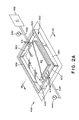
- Figure 2A is a perspective view, with a portion broken away, showing the manner of fabrication of the retort about the pack of metal sheets prior to effecting diffusion bonding.
- Figure 2B is a cross-sectional view of the retort and pack of metal sheets shown in Figure 2A taken along
section line 2B-2B in Figure 2A. - Figure 3A is a cross-sectional view of one tool assembly used to effect diffusion bonding as contemplated by the present invention, with the sealed retort being disposed between upper and lower press assembly tools in advance of effecting the step of diffusion bonding.
- Figure 3B is a cross-sectional view of a second tool assembly used to effect both diffusion bonding and superplastic preforming as contemplated by the present invention, with the sealed retort being disposed between upper and lower press assembly tools in advance of effecting the step of diffusion bonding.
- Figure 4 is a cross-sectional elevational view of a preferred embodiment of a forming apparatus used for fabrication of metal sandwich structures with the three-piece bonded metal sheet assembly of Figure 1 inserted therein.
- Figure 5 illustrates the fully expanded three-piece bonded metal sheet assembly within the forming apparatus of Figure 4, with the broken lines illustrating the final position of the component metal sheets of the expanded joined assembly.
- Figure 6 is a detail view of an inflation tube connection for the three-piece metal sheet assembly.
- Figures 7 and 8 are cross-sectional elevational views of a modified forming apparatus with a two- piece bonded metal sheet assembly inserted in an initial position in Figure 7 and in a final expanded position in Figure 8.
- Figure 9 is a cross-sectional elevational view of a modified forming apparatus illustrating a tapered three-piece bonded metal sheet assembly in final formed position with an attachment joined to the sandwich structure at the broken lines.
- Figure 10 is a partial perspective view of the formed sandwich structure of Figure 9.
- In order for superplastic forming to be successful, it is necessary to use a material that will exhibit superplastic properties. The extent to which the material selected will exhibit superplastic properties is predictable in general terms from a determination of the strain rate sensitivity and a design determination of the permissible variation in wall thickness. Strain rate sensitivity can be defined as

where - s = stress in pounds per square inch, and
- e = strain rate in reciprocal minutes.
- Strain rate sensitivity is determined by a well-known torsion test, and it has been found that a strain rate sensitivity of about 0.5 of greater will provide satisfactory results. The larger the value, the greater the superplastic properties. Maximum strain rate sensitivity in metals is seen to occur as metals are deformed near the phase transformation temperature. For titanium aluminide, the temperature range in which superplasticity can be observed is about 1750° F. to about 1900° F.
- Other variables have been found to affect strain rate sensitivity and therefore should be considered in selecting a suitable metal material. Decreasing grain size results in correspondingly higher values for strain rate sensitivity. Additionally, strain rate and material texture affect the strain rate sensitivity. It has been found that for titanium aluminide, the m value reaches a peak at an intermediate value of strain rate (approximately 2 x 10⁻⁴ in./in./sec.). For maximum stable deformation, superplastic forming should be done at or near this strain rate. Too great a variance from the optimum strain rate may result in loss of superplastic properties.
- Diffusion bonding, through which separate elements form a single unitary mass, has been practiced in a wide variety of metals and alloys. However, the quality of the bond and the parameters employed necessarily vary for each particular choice of workpiece material.
- The present invention is particularly directed to reactive metals which have surfaces that would be contaminated at the elevated temperatures required for superplastic forming and diffusion bonding, as for example titanium aluminides. These metals are also particularly well-suited for the process of the present invention because they exhibit very high superplastic properties in a temperature range suitable for diffusion bonding, i.e., about 1750° - 1900° F depending on the specific alloy used.
- Referring now to Figure 1, there is shown an exploded view of a three-piece metal sheet assembly to be formed into a sandwich structure according to the present invention. The assembly is made up of
metal blanks principal surfaces metal blanks - A suitable stop-off material is applied to selected areas within the stack of sheets where no attachment between the sheets is desired. Thus, as shown in Figure 1,
areas surfaces - Figures 2A and 2B illustrate a retort or container which has been formed about the stack of metal sheets for the purpose of insuring that when the diffusion bonding technique is carried out at a sufficiently high enough temperature suitable for such a process, such bonding process can be effected in a controlled, oxygen-free and contaminent-free environment.
- As shown in Figures 2A and 2B, the
retort 400 comprises atop sheet 402 of metal, preferably stainless steel, and abottom sheet 404 of metal, also preferably stainless steel. Preferably, the top and bottom sheets of the retort are secured in a substantially air-tight manner, such as by welding, about their periphery to sealingly envelope the metal sheet structure orstack 40.Vacuum grooves bottom sheet 404 of the retort and are disposed on opposite sides of themetal sheet stack 40. The grooves are positioned such that they extend from a respective stack edge within the retort outwardly to and through an adjacently located sealed edge of the retort. The vacuum grooves are important because they facilitate the creation of a vacuum within the sealed retort and within the stack. In this manner, a contamination- free and oxygen-free environment such as that referred to above can be maintained within the retort during the heat-up phase and the diffusion bonding phase of the process contemplated by the present invention. - To create a vacuum within the sealed retort, a
vacuum pump 432, which as shown in Figure 2A is interconnected with thevacuum grooves 412 via a vacuum line ortube 422, is actuated to apply negative pressure (suction) to the interior of the retort.Pump 432 is operated until thepressure guage 442 shows attainment of a predetermined vacuum level, optimally between 10-5 Torr and 10-6 Torr. Asecond gauge 444 is used to ensure that a vacuum has been attained throughout the retort. This is accomplished by coupling the gauge to the interior of the retort viatube 424 andvacuum grooves 414, and using the gauge to verify a vacuum throughout the entire retort. - A
metal seal frame 500 fabricated from stainless steel strips 502 is disposed atop thetop sheet 402 of the retort in such a manner as to be spaced from, yet parallel to, the edges of themetal stack 40. Theseal frame 500 is attached to thetop sheet 402 of the retort 400 (note Figure 2B) and eachstrip 502 includes aninner side 552, anouter side 554 and atop surface 556. The purpose of theseal frame 500 will be described below in connection with the apparatus used to achieve diffusion bonding of thestack 40 of metal sheets. - While the size of the
seal frame 500 depicted in the Figures is not accurately portrayed, it is intended to be a true representation of the manner of construction of the retort. In actual practice, it has been found that the most advantageous height of the seal frame strips 502 is preferably on the order of between 1/4" and 1/2". - Referring now to Figure 3A, there is shown one
apparatus 600 by which the process of diffusion bonding of thestack 40 of metal sheets may be accomplished. The apparatus includes anupper press member 610 and alower press member 620. Mounted on the exposed face of the upper press member is aplaten member 612, and anupper tool 614 is mounted on the exposed face of the upper platen member. Likewise, alower platen member 622 is mounted on the exposed face of thelower press member 620, and alower tool 624 is mounted on the exposed face of the lower platen member. The upper and lower platens are fabricated from ceramic materials. Preferably, the upper and lower tools are made from metals which possess excellent heat transfer characteristics. A horizontally extendinggas transfer passage 630 is provided in theupper tool 614 running from one side surface to a generally central location thereof.Gas transfer passage 630 is connected with a second, vertically extendinggas transfer passage 632 which runs from the central location in the upper tool to a central location in the exposed face of the upper tool. Apressure line 635 connects thegas transfer passage 630 with a source (not shown) of bonding gas under high pressure, and appropriate valve means for initiating and stopping the flow of gas to thegas transfer passage 630 for a purpose described in detail below. - When the retort assembly 400 (as depicted in Figure 2A) is positioned in an appropriate location on the lower tool of the press assembly, the upper and lower tools are moved relative to one another so that the spacing between the two tools is decreased. Preferably, the press assembly is fabricated such that the upper tool moves relative to the lower tool (i.e., where the lower tool is supported in a fixed position and the upper tool is movable relative to the lower tool). As the upper tool moves downwardly toward the lower tool, the exposed face of the upper tool engages the
top surface 556 of the metal strips of which the seal frame is composed. The upper tool is caused to move into engagement with the top surfaces of theseal frame 500 with sufficient downward pressure to create a sealed volume "V" defined between the upper surface of theretort top sheet 402, theinner sides 552 of the seal frame, and the lower exposed surface of the upper tool. Throughout the process, pump 432 is maintaining a vacuum within theretort 400. A heated environment is created aboutretort 400 while the retort is secured in thepress assembly 600. As the retort is heated to a temperature within the range of approximately 1700° F. to 1900° F, gas is pumped throughline 635 into the volume "V" so as to create enormous pressure within the volume "V" and thereby cause various surfaces of the metal sheets instack 40 to be pressed together and thereby experience diffusion bonding. After maintaining this high pressure and high heat environment for a predetermined period of time (of sufficient duration to accomplish diffusion bonding), the gas pressure is released, the temperature environment about the press assembly is cooled, the press assembly is opened and the retort is cooled to a sufficiently low enough temperature to permit removal of the top and bottom sheets of stainless steel, of which the retort has been fabricated, from about the now-bonded stack of metal sheets. - A second forming
apparatus 700 is shown in Figure 3B by which the processes of diffusion bonding and superplastic preforming of thestack 40 of metal sheets may be accomplished. This apparatus includes anupper press member 710 and alower press member 720. Mounted on the exposed face of the upper press member is aplaten member 712, and anupper shaping tool 714 is mounted on the exposed face of the upper platen member. Likewise, alower platen member 722 is mounted on the exposed face of thelower press member 720, and alower tool 724 is mounted on the exposed face of the lower platen member. - As with the first forming apparatus, the upper and lower platens of this apparatus preferably are fabricated from ceramic materials, and the upper and lower tools are made from metals which possess excellent heat transfer characteristics. However, in contrast to the first forming
apparatus 600 where theupper tool 614 is formed with a substantially planar exposed face, theupper shaping tool 714 of this forming apparatus is formed with a concave recess having generally spherical or cylindrical attributes. - A horizontally extending
gas transfer passage 730 is provided in theupper shaping tool 714 running from one side surface to a generally central location thereof.Gas transfer passage 730 is connected with a second, vertically extendinggas transfer passage 732 which runs from the central location in the upper shaping tool to a central location on the concave surface of the upper shaping tool. Apressure line 735 connects thegas transfer passage 730 of the upper tool with a source (not shown) of bonding gas under high pressure, and appropriate valve means for initiating and stopping the flow of gas to thegas transfer passage 730. - The
lower shaping tool 724 also is provided with a horizontally extendinggas transfer passage 740 running from one side surface of the lower shaping tool to a generally central location thereof.Gas transfer passage 740 is connected with a second, vertically extendinggas transfer passage 742 which runs from the central location in the upper shaping tool to a central location on the substantially planar surface of the lower shaping tool. Apressure line 745 connects thegas transfer passage 740 of the lower tool with a source (not shown) of bonding gas under high pressure, and appropriate valve means for initiating and stopping the flow of gas to thegas transfer passage 740. - Use of the apparatus disclosed in Figure 3B to effect diffusion bonding and superplastic preforming is similar in many ways to use of the apparatus shown in Figure 3A. Initially, the
retort assembly 400 shown in Figures 2A and 2B is modified by attaching aseal frame 800 on the downwardly facing surface of thebottom sheet 404. Theseal frame 800 has a construction similar to theseal frame 500 and is provided for a function similar to that ofseal frame 500. The modified retort assembly (identified in Figure 3B with the numeral 400' for sake of distinguishing over the retort assembly of Figure 3A) is then positioned in an appropriate location on thelower shaping tool 724 of the press assembly (see Figure 3B). The upper andlower tools seal frame 500, and the lower exposed arcuate surface of the upper shaping tool. The second of these volumes "V"' is defined by the lower surface of the retort bottom sheet 404', the inner side surfaces of theseal frame 800, and the upper exposed substantially planar surface of the lower tool. - Throughout this forming process, pump 432 is maintaining a vacuum within the retort 400'. A heated environment is created about retort 400' while the retort is secured in the
press assembly 700. As the retort is heated to a temperature within the range of approximately 1700° F. to 1900° F, gas is pumped throughline 735 into the volume "V" so as to create enormous pressure within the volume "V" and thereby cause various surfaces of the metal sheets instack 40 to be pressed together and thereby experience diffusion bonding. After maintaining this high pressure and high heat environment for a predetermined period of time (of sufficient duration to accomplish diffusion bonding), the gas pressure inline 735 is cut off and instead rerouted throughline 745. Now, delivery of the pressurized gas to the volume "V"', causes the diffusion bondedstack 40, while still in the evacuated retort 400' and still at the diffusion bonding temperature of between approximately 1700° F and 1900° F, to deform upwardly and engage with the arcuate shaping surface of theupper shaping tool 714. In this manner, thestack 40 undergoes diffusion bonding as well as preforming, all in a single thermal cycle. Once this diffusion bonding/preforming process is completed, the gas pressure in the volume "V"' is released, the temperature environment about thepress assembly 700 is cooled, the press assembly is opened and the retort is cooled to a sufficiently low enough temperature to permit removal of the top and bottom sheets of stainless steel, of which the retort has been fabricated, from about the now-diffusion bonded and superplastically preformedstack 40 of metal sheets. - With reference now to Figure 4, there is illustrated a
preferred apparatus 42 for effecting superplastic forming after the process of diffusion bonding, or diffusion bonding coupled with superplastic preforming, has been accomplished. As shown, the preferred apparatus includes anupper tool 44 has preferablyintegral side walls 45 in the form of a ring which can be of any desired shape. Alower tool 46, which preferably has the same outer area dimension asupper frame 44, can be flat and act as a base as illustrated for supporting the stack ofmetal blanks 40. For purposes of the claims, bothupper tool 44 andlower tool 46 are considered shaping members as both cooperate to form the desired shaped structure. The inner surface ofupper tool 44 defines aninner chamber 48 and a female die surface. One or more male die members (not shown) can be provided in thechamber 48 to vary the shape of the part to be formed. The stack ofmetal blanks 40, which is supported on thelower tool 46, covers thechamber 48. The metal blanks of the stack must all be of a material suitable for joining such as by welding, brazing or diffusion bonding. At least one of the outer metal blanks, and most likely the inner blanks, must have an effective strain rate sensitivity for exhibiting the superplastic properties at a desired forming temperature and preferably within a temperature range required for diffusion bonding of the stack. This is shown in Figure 5 by the expandedstack 40 where bothsheets stack 40 are determined by the dimensions of the parts to be formed. The joining method to be used, namely diffusion bonding, depends on the material selected for the metal blanks, the temperature required for superplastic forming, and the desired strength. However, especially for titanium aluminide, diffusion bonding is preferred as this results in the strongest joining, in contrast to other conventional methods of joining such as welding or brazing. Furthermore, the bonding temperature is generally suitable for superplastic forming. - As previously mentioned, stop-off can be used at
areas - Joining of the
stack 40 at selected locations is normally accomplished outside of the formingapparatus 42 before the stack is placed therein. The weight ofupper tool 44 acts as a clamping means for thestack 40. A single continuous edge of thestack 40 is effectively constrained between theupper tool 44 and thelower tool 46. This insures that the portions of the blanks of the stack to be formed will be stretched rather than drawn. Where desired, additional tightening means such as hydraulic jacks (not shown) can be employed to more effectively constrain thestack 40. Another additional tightening means that could be employed is a press (not shown), preferably hydraulic, havingplatens 50. Formingapparatus 42 is positioned betweenplatens 50 and compressed thereby assuring thatstack 40 is effectively constrained andchamber 48 sealed from the air. This arrangement is particularly advantageous as theplatens 50 can be made of ceramic material and resistance heatedwires 52 can be provided therein forheating stack 40 to the forming temperature. Other heating methods could be used with the formingapparatus 42 ordinarily surrounded by a heating means if the heating platens are not used. - Alternatively, an environmental control system could be provided for contamination prevention and diffusion bonding of the
stack 40 when the latter is unjoined within the formingapparatus 42. The purpose of this system is to ensure that thestack 40 is exposed only to inert gas during heating, bonding and forming by fluid pressure. The metal blanks ofstack 40 will not react with inert gas due to the nature of such gas, even at the elevated bonding and forming temperatures. Thus, in this environment, contamination of the stack will be minimized. -
Line 52 is connected to a source of pressurized inert gas at one end (not shown) and tochamber 48 throughorifice 54 in theupper tool 44. Avalve 56 for governing the flow of inert gas throughline 52 intochamber 48 and apressure gauge 58 to indicate pressure are provided. The inert gas used is preferably argon in gaseous form.Line 52 also functions as an outlet for inert gas inchamber 48 and could also be connected to a source of vacuum, such as a suction pump (not shown) for creating vacuum inchamber 48. Whenline 52 is used as an outlet,valve 56 governs the flow of inert gas from thechamber 48. Anadditional line 60 is optimally provided on the opposite side of thetool 44. Thisline 60 is connected to thechamber 48 throughorifice 62 in theupper tool 44 and functions as an outlet for inert gas inchamber 48. Avalve 64 is provided inline 60 for regulation of inert gas flow from thechamber 48.Line 60 can simply function as a vent or be connected to a source of vacuum, such as a suction pump (not shown). - In the alternative method, the contamination prevention system can also function as a means for effecting gas pressure diffusion bonding of
stack 40. Thus, whenstack 40 is placed in formingapparatus 42 as shown in Figure 2, the stack can be heated in an inert gas atmosphere to a suitable diffusion bonding temperature (approximately 1800° F. when the metal blanks ofstack 40 are of alpha-2 titanium aluminide materials) by heat generated fromheating platens 50, and then applying pressure to stack 40 by increasing the pressure inchamber 48 by adding additional pressurized inert gas throughline 52 while maintainingline 60 closed viavalve 64. In this manner, the untreated areas ofstack 40 will be diffusion bonded by the application of such pressure, which is preferably approximately 900 psi for alpha-2 materials, for a suitable forming time (which depends on the thickness of thestack 40 and may vary from 30 minutes to 12 hours). The edges of the blanks ofstack 40 may also be diffusion bonded if desired by virtue of sealing pressure thereon in the form of the weight ofupper tooling 44 and optionally pressure from a press and/or a clamping means. Afterdiffusion bonding stack 40, the excess inert gas would be removed fromchamber 48 throughlines stack 40. - For expansion of
stack 40 to the configuration shown in Figure 5,expansion tubes expansion tube 74 located on the opposite side of stack 40) is positioned betweenmetal blanks 10 and 14, and protrudes into achannel 75 defined by therecesses surface 20 of metal blank 14 which overlies therecess 78.Recesses blanks 10 and 12, respectively, to provide a channel forinflation tube 74. The positioning ofexpansion tube 72 in such a channel prevents compression oftube 72 by thetools tube 72 so that it protrudes only partially into thechannel 75, inert gas will flow fairly evenly between the metal blanks of thestack 40, in this case on either side of the blank 12 as shown byarrows 80 and 82. As shown in Figure 4,expansion tubes valves pressure gauges -
Expansion tubes tube 72 could act as an inlet andtube 74 an outlet with inert gas flow being transmitted throughstack 40 prior to expansion of the stack to draw off the vaporized binder. - A pair of lateral grooves (only one
groove 73 of the pair is shown in Figure 6) are provided on opposite sides of thelower tool 46 with the onegroove 73 being in alignment withrecess 76 and the other groove (not shown) being positioned for alignment withrecess 77. The lateral grooves are provided to insure that passage of inert gas frominflation tubes stack 40 is not prevented from reaching treatedareas lower tools recesses areas - As shown in Figure 1, when treating as by stop-off selected areas of
stack 40 to prevent diffusion bonding thereon, additional areas such as that shown at 92 and 94 should likewise be treated to prevent bonding thereon so that the gas frominflation tubes stack 40.Apertures 96 are provided in the treatedareas inflation tubes - In order to make the expanded metallic sandwich structure as shown in Figure 5 according to applicant's inventive method, metal
blank workpieces sheets apparatus 42 before forming. The pressure inchamber 48 would be increased by flow of pressurized inert gas throughline 52 intochamber 48. Oncechamber 48 had an inert gas atmosphere, the stack would be heated byresistance wires 52 inheating platens 50 to a temperature which optimally would be suitable for both diffusion bonding and superplastic forming, although the temperature could later be raised or lowered if a different temperature is required for superplastic forming. The pressure inchamber 48 would be increased by additional pressurized inert gas throughline 52 to a pressure suitable for diffusion bonding ofstack 40. That pressure would be maintained for a time duration sufficient for diffusion bonding. When the metal blanks of the stack are of alpha-2, the temperature used would be approximately 1800° F. and the pressure about 800-900 psi. These values can, of course, be varied during forming and bonding as long as they are maintained within a suitable range, i.e., in which the values would be sufficient for diffusion bonding and/or superplastic forming. The time duration will vary depending upon the alloys used, temperature, pressure, and thickness of thestack 40. Duration may vary from 30 minutes to 15 hours, but three (3) hours is a fairly representative expectation. As previously stated, bonding temperature may vary from about 1750° F. to about 1900° F. Gas bonding pressure may vary from about 800 psi to 2000 psi or more with the preferred range being from about 800 to about 900 psi. - Before expanding the
stack 40, the pressure inchamber 48 is reduced throughlines lines chamber 48 throughlines tubes chamber 48. The pressure differential normally used for superplastic forming of alpha-2 is normally in a range of from about 800 to 900 psi.Metal blank 14 is initially lifted by the pressure differential and pulls with it at the selected joinedareas metal blank 12. Such expansion allows the pressurized inert gas to flow throughapertures 96 to provide an equal pressure within the stack so that the core (workpiece 12) is formed uniformly. The equal pressure also retains metal blank 10 of the stack in its initial position, the latter being forced against the base orlower tool 46. - Figures 7 and 8 show a modified forming
apparatus 130 and the use of a different technique for selective joining. The use of a two-sheet stack 132 withmetal blanks Stack 132 could be joined as by diffusion bonding, brazing, or spot welding prior to the insertion in the formingapparatus 130. If diffusion bonded, themetal blanks - Forming
apparatus 130 utilizes anupper tool 140 having a lower arcuate surface defined by a plurality ofprotuberances 142 spaced from one another by intermediate recesses orchambers 144.Lower tool 150 has an upperarcuate surface 152 complimentary to that formed by theprotuberances 142.Inflation tubes metal blanks Blanks 134 and 136 (similar torecesses tubes Lines lines chamber 144 and act as vents or connection to sources of vacuum for drawing out the inert gas from thechambers 144 for superplastically expandingmetal blank 134 within those chambers. Each of thetubes chambers 144.Tubes chambers 144. - Depending on the thickness and desired curvature of
stack 132, the stack can be preformed to such a shape prior to insertion in formingapparatus 130 by conventional sheet metal forming, such as by roll forming or superplastic forming, or subsequent to insertion in formingapparatus 130 by pressure applied to the stack by theprotuberances 142 ofupper tool 140 andsurface 152 oflower tool 150. Preforming in the formingapparatus 130 is preferable as the preforming and selective diffusion bonding are accomplished simultaneously when the stack is also unjoined prior to insertion in the forming apparatus, thereby saving fabrication time and equipment costs. - Using this forming
apparatus 130, the unjoined stack can be diffusion bonded by application of pressure fromupper tool 140 andlower tool 150 at required temperature for a suitable time duration. By virtue ofprotuberances 142, the pressure is only applied to selected areas of the stack so that only those areas are diffusion bonded, thereby allowing for expansion in the unbonded areas. - After diffusion bonding (or insertion into the forming apparatus if the stack has already been joined) and preforming,
stack 132 is inflated by flow of inert gas throughlines chambers 144. Optimally, a vacuum would be applied tochambers 144 throughlines chambers 144, only metal blank 134 is expanded and consequently only that blank must be of a material suitable for superplastic forming. It is seen from the above that diffusion bonding, pre-forming, and superplastic expansion can all be done in the same apparatus in one operation. - Figure 9 illustrates the forming of a variably shaped structure, the latter being shown as a tapered sandwich structure with an attachment joined thereto. Applicant accomplishes tapering of the sandwich structure by suitably designing the corresponding shaping surface of the upper tool. In Figure 9, the
upper tool 170 has anupper shaping surface 172 which angles downwardly from one side to the other (shown as left to right). Thus, when theupper metal blank 174 ofstack 176 is superplastically expanded againstsurface 172, it is shaped into the taper of such surface. The core formed byblank member 178 ofstack 176 is also tapered by virtue of its dependence upon the movement of upper blank 174. -
Attachment 180, shown in an arbitrary design, is joined to thestack 176 on theupper member 174 alongbond line 183 during the superplastic expansion of the stack in the same forming apparatus, thereby lowering fabrication time, apparatus cost, and forming difficulty. Anattachment 180 could be positioned within a suitably shapedgroove 182 where the attachment may or may not protrude from such groove, or be located in the forming chamber, without the use of a groove so that it forms either a male or female shaping surface itself. For purposes of the claims, when a groove is used, it is considered part of the forming chamber, so that the attachment is positioned within the chamber when in the groove. In the embodiment illustrated, when the stack is superplastically expanded, itcontacts attachment 180 alongbond line 183. By virtue of the superplastic forming temperature, the attachment is also heated, and the pressure expanding the stack eventually forces the upper member to bear againstsurface 172 and the attachment. The attachment is then diffusion bonded to the stack alongbond line 183 when the temperature and pressure are maintained at a required diffusion bonding level for a suitable time duration. Optimally, the temperature and pressure for superplastic forming ofmembers member 174, and preferably of a like material. As the superplastic forming gas pressure typically used is 900 psi, a pressure considerably less than the 2000psi used normally in diffusion bonding, the bond which results may not develop full parent metal strength, but would likely be analogous to a high quality braze joint. However, once the sandwich structure is fully expanded, as shown in Figure 9, the pressure can be increased within the expanded sandwich throughinflation tubes - A close-out such as shown at 194 can also be formed to the expanded sandwich structure in the same operation by diffusion bonding the close out, which comprises an unexpanded end of the
stack 176, by heating the stack to the diffusion bonding temperature with application of pressure by upper andlower tools sandwich structure 200 of Figure 9 removed from the forming apparatus is shown at Figure 10 with the side ends cut off.
Claims (7)
Applications Claiming Priority (2)
| Application Number | Priority Date | Filing Date | Title |
|---|---|---|---|
| US07/680,457 US5118026A (en) | 1991-04-05 | 1991-04-05 | Method for making titanium aluminide metallic sandwich structures |
| US680457 | 1991-04-05 |
Publications (3)
| Publication Number | Publication Date |
|---|---|
| EP0507067A2 true EP0507067A2 (en) | 1992-10-07 |
| EP0507067A3 EP0507067A3 (en) | 1992-10-28 |
| EP0507067B1 EP0507067B1 (en) | 1995-02-01 |
Family
ID=24731196
Family Applications (1)
| Application Number | Title | Priority Date | Filing Date |
|---|---|---|---|
| EP92102881A Expired - Lifetime EP0507067B1 (en) | 1991-04-05 | 1992-02-20 | Method for making titanium aluminide metallic sandwich structures |
Country Status (4)
| Country | Link |
|---|---|
| US (1) | US5118026A (en) |
| EP (1) | EP0507067B1 (en) |
| JP (1) | JPH06226467A (en) |
| DE (1) | DE69201319T2 (en) |
Cited By (11)
| Publication number | Priority date | Publication date | Assignee | Title |
|---|---|---|---|---|
| FR2754478A1 (en) * | 1996-10-16 | 1998-04-17 | Snecma | PROCESS FOR MANUFACTURING A HOLLOW BLADE OF A TURBOMACHINE |
| WO2001000349A1 (en) * | 1999-06-28 | 2001-01-04 | Institut Problem Sverkhplastichnosti Metallov Ran | Method of producing a multilayer cellular structure |
| WO2006047066A1 (en) * | 2004-10-21 | 2006-05-04 | The Boeing Company | Formed structural assembly and associated preform and method |
| WO2007058906A1 (en) * | 2005-11-10 | 2007-05-24 | The Boeing Company | Method of superplastic forming of titanium assemblies and aircraft structure manufactured thereby |
| US7533794B2 (en) | 2004-03-31 | 2009-05-19 | The Boring Company | Superplastic forming and diffusion bonding of fine grain titanium |
| RU2509638C1 (en) * | 2012-11-29 | 2014-03-20 | Открытое акционерное общество "Военно-промышленная корпорация "Научно-производственное объединение машиностроения" | Method of making metallic sandwiched panels |
| RU2545854C2 (en) * | 2013-08-22 | 2015-04-10 | Открытое акционерное общество "Военно-промышленная корпорация "Научно-производственное объединение машиностроения" | Method of making multilayer metal panels |
| RU2555259C1 (en) * | 2013-12-25 | 2015-07-10 | Акционерное общество "Военно-промышленная корпорация "Научно-производственное объединение машиностроения" (АО "ВПК "НПО машиностроения") | Method of metal panels manufacturing |
| CN106466898A (en) * | 2015-08-17 | 2017-03-01 | 波音公司 | For making equipment and the method for the shaping of three-plate type panel |
| CN107790540A (en) * | 2016-09-06 | 2018-03-13 | 波音公司 | There is the method for the sandwich construction of monolithic attachment members for superplasticforming |
| US10569504B2 (en) | 2017-02-27 | 2020-02-25 | The Boeing Company | Panel and method of forming a three-sheet panel |
Families Citing this family (58)
| Publication number | Priority date | Publication date | Assignee | Title |
|---|---|---|---|---|
| US5587098A (en) * | 1991-04-05 | 1996-12-24 | The Boeing Company | Joining large structures using localized induction heating |
| US5641422A (en) | 1991-04-05 | 1997-06-24 | The Boeing Company | Thermoplastic welding of organic resin composites using a fixed coil induction heater |
| US5808281A (en) | 1991-04-05 | 1998-09-15 | The Boeing Company | Multilayer susceptors for achieving thermal uniformity in induction processing of organic matrix composites or metals |
| US5723849A (en) | 1991-04-05 | 1998-03-03 | The Boeing Company | Reinforced susceptor for induction or resistance welding of thermoplastic composites |
| US5747179A (en) * | 1991-04-05 | 1998-05-05 | The Boeing Company | Pack for inductively consolidating an organic matrix composite |
| US5420400A (en) * | 1991-10-15 | 1995-05-30 | The Boeing Company | Combined inductive heating cycle for sequential forming the brazing |
| US5599472A (en) * | 1991-04-05 | 1997-02-04 | The Boeing Company | Resealable retort for induction processing of organic matrix composites or metals |
| US5645744A (en) | 1991-04-05 | 1997-07-08 | The Boeing Company | Retort for achieving thermal uniformity in induction processing of organic matrix composites or metals |
| US5624594A (en) | 1991-04-05 | 1997-04-29 | The Boeing Company | Fixed coil induction heater for thermoplastic welding |
| US5728309A (en) | 1991-04-05 | 1998-03-17 | The Boeing Company | Method for achieving thermal uniformity in induction processing of organic matrix composites or metals |
| US5793024A (en) | 1991-04-05 | 1998-08-11 | The Boeing Company | Bonding using induction heating |
| US5710414A (en) | 1991-04-05 | 1998-01-20 | The Boeing Company | Internal tooling for induction heating |
| US7126096B1 (en) | 1991-04-05 | 2006-10-24 | Th Boeing Company | Resistance welding of thermoplastics in aerospace structure |
| US5410132A (en) | 1991-10-15 | 1995-04-25 | The Boeing Company | Superplastic forming using induction heating |
| US5401583A (en) * | 1991-08-02 | 1995-03-28 | Rockwell International Corporation | Gas manifolding for super plastic forming and diffusion bonding of truss core sandwiches |
| US5705794A (en) * | 1991-10-15 | 1998-01-06 | The Boeing Company | Combined heating cycles to improve efficiency in inductive heating operations |
| US6087640A (en) * | 1991-10-15 | 2000-07-11 | The Boeing Company | Forming parts with complex curvature |
| US5914064A (en) * | 1991-10-15 | 1999-06-22 | The Boeing Company | Combined cycle for forming and annealing |
| US5273202A (en) * | 1991-10-29 | 1993-12-28 | Rolls-Royce Plc | Method of manufacturing an article, a method of diffusion bonding and a vacuum chamber |
| GB9122874D0 (en) * | 1991-10-29 | 1991-12-11 | Rolls Royce Plc | A method of manufacturing an article,a method of diffusion bonding and a vacuum chamber |
| DE4241421C2 (en) * | 1992-12-09 | 1995-01-12 | Mtu Muenchen Gmbh | Process for manufacturing voided components and uses of the process |
| GB9225702D0 (en) * | 1992-12-09 | 1993-02-03 | British Aerospace | Forming of diffusion bonded joints in superplastically formed metal structures |
| US5289965A (en) * | 1993-04-30 | 1994-03-01 | Mcdonnell Douglas Corporation | Method of superplastically forming and braze bonding a structure |
| JP3398246B2 (en) * | 1995-02-24 | 2003-04-21 | 日本飛行機株式会社 | Metal sandwich structure and method of manufacturing the same |
| USH1659H (en) * | 1995-05-08 | 1997-07-01 | The United States Of America As Represented By The Secretary Of The Air Force | Method for heat treating titanium aluminide alloys |
| DE69629398T2 (en) * | 1996-01-12 | 2004-01-22 | The Boeing Co., Seattle | MULTILAYER METALLIC SANDWICH STRUCTURES |
| WO1998024569A1 (en) * | 1996-12-03 | 1998-06-11 | Elpatronic Ag | Method for producing a molded part and a molded part produced according to said method |
| US6129257A (en) * | 1999-12-01 | 2000-10-10 | Allison Engine Company, Inc. | High temperature brazing fixture |
| US6511759B1 (en) * | 2000-02-07 | 2003-01-28 | Carl Schalansky | Means and method for producing multi-element laminar structures |
| JP4530495B2 (en) * | 2000-07-03 | 2010-08-25 | 富士重工業株式会社 | Method for integrally forming superplastic materials |
| FR2818015B1 (en) * | 2000-12-08 | 2003-09-26 | Centre Nat Rech Scient | METHOD FOR MANUFACTURING METAL / CERAMIC COMPOSITE THIN FILMS |
| US6793829B2 (en) * | 2002-02-27 | 2004-09-21 | Honeywell International Inc. | Bonding for a micro-electro-mechanical system (MEMS) and MEMS based devices |
| US6884966B2 (en) * | 2002-10-22 | 2005-04-26 | The Boeing Company | Method and apparatus for forming and heat treating structural assemblies |
| JP2006506525A (en) * | 2002-11-15 | 2006-02-23 | ユニバーシティ・オブ・ユタ・リサーチ・ファウンデーション | Integrated titanium boride coating on titanium surfaces and related methods |
| FR2853572B1 (en) * | 2003-04-10 | 2005-05-27 | Snecma Moteurs | METHOD FOR MANUFACTURING A HOLLOW MECHANICAL WELDING-DIFFUSION MECHANICAL PIECE AND SUPERPLASTIC FORMING |
| US6747253B1 (en) * | 2003-05-07 | 2004-06-08 | The Boeing Company | Method and apparatus for induction heat treatment of structural members |
| US6914225B2 (en) * | 2003-06-18 | 2005-07-05 | The Boeing Company | Apparatus and methods for single sheet forming using induction heating |
| ATE393699T1 (en) * | 2004-02-26 | 2008-05-15 | Geesthacht Gkss Forschung | METHOD FOR PRODUCING COMPONENTS OR SEMI-FINISHED PRODUCTS THAT CONTAIN INTERMETALLIC TITANIUM ALUMINIDE ALLOYS, AND COMPONENTS THAT CAN BE PRODUCED BY MEANS OF THE METHOD |
| DE602005008141D1 (en) * | 2004-07-28 | 2008-08-28 | Nissan Motor | Preform, hydroforming and hydroforming molded product |
| US7256364B2 (en) * | 2004-12-21 | 2007-08-14 | Remy International, Inc. | Method for simultaneous resistance brazing of adjacent conductor joints |
| JP4289300B2 (en) * | 2005-01-06 | 2009-07-01 | ブラザー工業株式会社 | Metal plate joining method |
| US7459105B2 (en) * | 2005-05-10 | 2008-12-02 | University Of Utah Research Foundation | Nanostructured titanium monoboride monolithic material and associated methods |
| WO2008154045A1 (en) | 2007-06-12 | 2008-12-18 | Rolls-Royce Corporation | System, methods, and apparatus for repair of components |
| US10843291B2 (en) * | 2008-11-15 | 2020-11-24 | The Boeing Company | Welding in preparation for superplastic forming |
| US20100176339A1 (en) * | 2009-01-12 | 2010-07-15 | Chandran K S Ravi | Jewelry having titanium boride compounds and methods of making the same |
| US8318251B2 (en) * | 2009-09-30 | 2012-11-27 | General Electric Company | Method for coating honeycomb seal using a slurry containing aluminum |
| DE102011102087A1 (en) * | 2011-05-19 | 2012-11-22 | Formtech Gmbh | Method for processing a surface element |
| CN102744517B (en) * | 2012-07-05 | 2015-04-15 | 北京科技大学 | Method for manufacturing dual-phase stainless steel hollow sandwich structure element |
| US20140335368A1 (en) * | 2013-05-13 | 2014-11-13 | Ford Global Technologies, Llc | Method Of Fabricating Roll-Bonded Expanded Load-Bearing Aluminum Laminate Structural Elements For Vehicle |
| GB201318527D0 (en) * | 2013-10-21 | 2013-12-04 | Rolls Royce Plc | Hollow component manufacture |
| US20160023439A1 (en) * | 2014-07-22 | 2016-01-28 | General Electric Company | Method for joining high temperature materials and articles made therewith |
| US10941455B2 (en) * | 2016-05-25 | 2021-03-09 | The Boeing Company | Sandwich structure and associated pressure-based forming method |
| CN106270095B (en) * | 2016-08-16 | 2018-07-10 | 北京航星机器制造有限公司 | A kind of band reinforcing rib part superplastic forming & diffusion bonding integral forming mold and method |
| CN108326395B (en) * | 2016-11-18 | 2020-06-12 | 中国航空制造技术研究院 | Preparation method of superplastic forming/diffusion connection three-layer hollow component |
| EP3636364A1 (en) * | 2018-10-09 | 2020-04-15 | Outokumpu Oyj | Method for manufacturing a crash frame of a battery compartment for battery electric vehicles |
| US11865809B2 (en) * | 2019-08-22 | 2024-01-09 | The Boeing Company | Method for forming non-bonded regions in multi-layered metallic armor |
| KR102269614B1 (en) * | 2020-11-10 | 2021-06-28 | 안혁 | A Pouch of Secondary Battery Foming Device |
| US20230271242A1 (en) * | 2022-02-28 | 2023-08-31 | Spirit Aerosystems, Inc. | Method for forming and heat treating near net shape complex structures from sheet metal |
Citations (7)
| Publication number | Priority date | Publication date | Assignee | Title |
|---|---|---|---|---|
| GB2095137A (en) * | 1981-03-23 | 1982-09-29 | Rockwell International Corp | A method of making filamentary reinforced metallic structures |
| GB2109711A (en) * | 1981-11-24 | 1983-06-08 | Grumman Aerospace Corp | Method for superplastic forming and diffusion bonding complex continuous structures |
| US4426032A (en) * | 1981-09-10 | 1984-01-17 | The United States Of America As Represented By The Secretary Of The Air Force | Tool sealing arrangement and method |
| EP0229954A2 (en) * | 1986-01-23 | 1987-07-29 | Dornier Gmbh | Process for manufacturing integral construction elements of highly steady aluminium |
| US4691857A (en) * | 1985-11-07 | 1987-09-08 | Trw Inc. | Method of shaping a workpiece |
| US4882823A (en) * | 1988-01-27 | 1989-11-28 | Ontario Technologies Corp. | Superplastic forming diffusion bonding process |
| EP0358523A1 (en) * | 1988-09-09 | 1990-03-14 | British Aerospace Public Limited Company | Domed structures and a method of making them by superplastic forming and diffusion bonding |
Family Cites Families (6)
| Publication number | Priority date | Publication date | Assignee | Title |
|---|---|---|---|---|
| US4220276A (en) * | 1978-08-25 | 1980-09-02 | Rockwell International Corporation | Method for fabricating superplastically formed/diffusion bonded structures |
| US3927817A (en) * | 1974-10-03 | 1975-12-23 | Rockwell International Corp | Method for making metallic sandwich structures |
| US3920175A (en) * | 1974-10-03 | 1975-11-18 | Rockwell International Corp | Method for superplastic forming of metals with concurrent diffusion bonding |
| US3980220A (en) * | 1974-12-05 | 1976-09-14 | The United States Of America As Represented By The Secretary Of The Navy | Method of fabricating large titanium pressure hulls |
| US4087037A (en) * | 1976-07-09 | 1978-05-02 | Mcdonnell Douglas Corporation | Method of and tools for producing superplastically formed and diffusion bonded structures |
| US4811890A (en) * | 1983-05-07 | 1989-03-14 | Rockwell International Corporation | Method of eliminating core distortion in diffusion bonded and uperplastically formed structures |
-
1991
- 1991-04-05 US US07/680,457 patent/US5118026A/en not_active Expired - Fee Related
-
1992
- 1992-02-20 EP EP92102881A patent/EP0507067B1/en not_active Expired - Lifetime
- 1992-02-20 DE DE69201319T patent/DE69201319T2/en not_active Expired - Fee Related
- 1992-04-03 JP JP4081282A patent/JPH06226467A/en not_active Withdrawn
Patent Citations (7)
| Publication number | Priority date | Publication date | Assignee | Title |
|---|---|---|---|---|
| GB2095137A (en) * | 1981-03-23 | 1982-09-29 | Rockwell International Corp | A method of making filamentary reinforced metallic structures |
| US4426032A (en) * | 1981-09-10 | 1984-01-17 | The United States Of America As Represented By The Secretary Of The Air Force | Tool sealing arrangement and method |
| GB2109711A (en) * | 1981-11-24 | 1983-06-08 | Grumman Aerospace Corp | Method for superplastic forming and diffusion bonding complex continuous structures |
| US4691857A (en) * | 1985-11-07 | 1987-09-08 | Trw Inc. | Method of shaping a workpiece |
| EP0229954A2 (en) * | 1986-01-23 | 1987-07-29 | Dornier Gmbh | Process for manufacturing integral construction elements of highly steady aluminium |
| US4882823A (en) * | 1988-01-27 | 1989-11-28 | Ontario Technologies Corp. | Superplastic forming diffusion bonding process |
| EP0358523A1 (en) * | 1988-09-09 | 1990-03-14 | British Aerospace Public Limited Company | Domed structures and a method of making them by superplastic forming and diffusion bonding |
Cited By (19)
| Publication number | Priority date | Publication date | Assignee | Title |
|---|---|---|---|---|
| EP0836899A1 (en) * | 1996-10-16 | 1998-04-22 | Societe Nationale D'etude Et De Construction De Moteurs D'aviation "Snecma" | Method of fabricating a hollow turbine blade |
| US5896658A (en) * | 1996-10-16 | 1999-04-27 | Societe Nationale D'etude Et De Construction De Moteurs D'aviation "Snecma" | Method of manufacturing a hollow blade for a turbomachine |
| FR2754478A1 (en) * | 1996-10-16 | 1998-04-17 | Snecma | PROCESS FOR MANUFACTURING A HOLLOW BLADE OF A TURBOMACHINE |
| WO2001000349A1 (en) * | 1999-06-28 | 2001-01-04 | Institut Problem Sverkhplastichnosti Metallov Ran | Method of producing a multilayer cellular structure |
| US7533794B2 (en) | 2004-03-31 | 2009-05-19 | The Boring Company | Superplastic forming and diffusion bonding of fine grain titanium |
| US7850058B2 (en) | 2004-03-31 | 2010-12-14 | The Boeing Company | Superplastic forming of titanium assemblies |
| WO2006047066A1 (en) * | 2004-10-21 | 2006-05-04 | The Boeing Company | Formed structural assembly and associated preform and method |
| US7210611B2 (en) | 2004-10-21 | 2007-05-01 | The Boeing Company | Formed structural assembly and associated preform and method |
| US7967240B2 (en) | 2004-10-21 | 2011-06-28 | The Boeing Company | Formed structural assembly and associated preform and method |
| US8329312B2 (en) | 2004-10-21 | 2012-12-11 | The Boeing Company | Formed structural assembly and associated preform |
| WO2007058906A1 (en) * | 2005-11-10 | 2007-05-24 | The Boeing Company | Method of superplastic forming of titanium assemblies and aircraft structure manufactured thereby |
| RU2509638C1 (en) * | 2012-11-29 | 2014-03-20 | Открытое акционерное общество "Военно-промышленная корпорация "Научно-производственное объединение машиностроения" | Method of making metallic sandwiched panels |
| RU2545854C2 (en) * | 2013-08-22 | 2015-04-10 | Открытое акционерное общество "Военно-промышленная корпорация "Научно-производственное объединение машиностроения" | Method of making multilayer metal panels |
| RU2555259C1 (en) * | 2013-12-25 | 2015-07-10 | Акционерное общество "Военно-промышленная корпорация "Научно-производственное объединение машиностроения" (АО "ВПК "НПО машиностроения") | Method of metal panels manufacturing |
| CN106466898A (en) * | 2015-08-17 | 2017-03-01 | 波音公司 | For making equipment and the method for the shaping of three-plate type panel |
| US10112229B2 (en) | 2015-08-17 | 2018-10-30 | The Boeing Company | Apparatus and method for forming three-sheet panels |
| CN106466898B (en) * | 2015-08-17 | 2020-01-31 | 波音公司 | Apparatus and method for forming three-panel panels |
| CN107790540A (en) * | 2016-09-06 | 2018-03-13 | 波音公司 | There is the method for the sandwich construction of monolithic attachment members for superplasticforming |
| US10569504B2 (en) | 2017-02-27 | 2020-02-25 | The Boeing Company | Panel and method of forming a three-sheet panel |
Also Published As
| Publication number | Publication date |
|---|---|
| JPH06226467A (en) | 1994-08-16 |
| EP0507067A3 (en) | 1992-10-28 |
| DE69201319D1 (en) | 1995-03-16 |
| US5118026A (en) | 1992-06-02 |
| EP0507067B1 (en) | 1995-02-01 |
| DE69201319T2 (en) | 1995-09-21 |
Similar Documents
| Publication | Publication Date | Title |
|---|---|---|
| EP0507067B1 (en) | Method for making titanium aluminide metallic sandwich structures | |
| US3927817A (en) | Method for making metallic sandwich structures | |
| CA1055680A (en) | Method for making metallic sandwich structures | |
| US4117970A (en) | Method for fabrication of honeycomb structures | |
| US4361262A (en) | Method of making expanded sandwich structures | |
| US4331284A (en) | Method of making diffusion bonded and superplastically formed structures | |
| US4811890A (en) | Method of eliminating core distortion in diffusion bonded and uperplastically formed structures | |
| US4429824A (en) | Delta-alpha bond/superplastic forming method of fabricating titanium structures and the structures resulting therefrom | |
| US3920175A (en) | Method for superplastic forming of metals with concurrent diffusion bonding | |
| US4406393A (en) | Method of making filamentary reinforced metallic structures | |
| US5692881A (en) | Hollow metallic structure and method of manufacture | |
| US4934580A (en) | Method of making superplastically formed and diffusion bonded articles and the articles so made | |
| US4951491A (en) | Apparatus and method for superplastic forming | |
| US4691857A (en) | Method of shaping a workpiece | |
| US5363555A (en) | Method of manufacturing an article by superplastic forming and diffusion bonding | |
| EP1872882A2 (en) | Method for producing an article by superplastic shaping and diffusion welding | |
| EP0414731B1 (en) | Curved superplastic forming/diffusion bonding sandwich fabricated structures | |
| US5323536A (en) | Method of manufacturing an article by superplastic forming and diffusion bonding | |
| US5479705A (en) | Method of manufacturing an article by superplastic forming and diffusion bonding | |
| US4559797A (en) | Method for forming structural parts | |
| US5253796A (en) | Retort for gas diffusion bonding of metals under vacuum | |
| GB2269556A (en) | A method of manufacturing an article by diffusion bonding | |
| US5139887A (en) | Superplastically formed cellular article | |
| US4509671A (en) | Method of producing diffusion bonded superplastically formed structures | |
| US4113522A (en) | Method of making a metallic structure by combined superplastic forming and forging |
Legal Events
| Date | Code | Title | Description |
|---|---|---|---|
| PUAI | Public reference made under article 153(3) epc to a published international application that has entered the european phase |
Free format text: ORIGINAL CODE: 0009012 |
|
| PUAL | Search report despatched |
Free format text: ORIGINAL CODE: 0009013 |
|
| AK | Designated contracting states |
Kind code of ref document: A2 Designated state(s): DE FR GB |
|
| AK | Designated contracting states |
Kind code of ref document: A3 Designated state(s): DE FR GB |
|
| 17P | Request for examination filed |
Effective date: 19921201 |
|
| 17Q | First examination report despatched |
Effective date: 19930811 |
|
| GRAA | (expected) grant |
Free format text: ORIGINAL CODE: 0009210 |
|
| AK | Designated contracting states |
Kind code of ref document: B1 Designated state(s): DE FR GB |
|
| ET | Fr: translation filed | ||
| REF | Corresponds to: |
Ref document number: 69201319 Country of ref document: DE Date of ref document: 19950316 |
|
| PLBE | No opposition filed within time limit |
Free format text: ORIGINAL CODE: 0009261 |
|
| STAA | Information on the status of an ep patent application or granted ep patent |
Free format text: STATUS: NO OPPOSITION FILED WITHIN TIME LIMIT |
|
| 26N | No opposition filed | ||
| REG | Reference to a national code |
Ref country code: GB Ref legal event code: IF02 |
|
| PGFP | Annual fee paid to national office [announced via postgrant information from national office to epo] |
Ref country code: FR Payment date: 20030131 Year of fee payment: 12 |
|
| PGFP | Annual fee paid to national office [announced via postgrant information from national office to epo] |
Ref country code: GB Payment date: 20030212 Year of fee payment: 12 |
|
| PGFP | Annual fee paid to national office [announced via postgrant information from national office to epo] |
Ref country code: DE Payment date: 20030228 Year of fee payment: 12 |
|
| PG25 | Lapsed in a contracting state [announced via postgrant information from national office to epo] |
Ref country code: GB Free format text: LAPSE BECAUSE OF NON-PAYMENT OF DUE FEES Effective date: 20040220 |
|
| PG25 | Lapsed in a contracting state [announced via postgrant information from national office to epo] |
Ref country code: DE Free format text: LAPSE BECAUSE OF NON-PAYMENT OF DUE FEES Effective date: 20040901 |
|
| GBPC | Gb: european patent ceased through non-payment of renewal fee |
Effective date: 20040220 |
|
| PG25 | Lapsed in a contracting state [announced via postgrant information from national office to epo] |
Ref country code: FR Free format text: LAPSE BECAUSE OF NON-PAYMENT OF DUE FEES Effective date: 20041029 |
|
| REG | Reference to a national code |
Ref country code: FR Ref legal event code: ST |