EP0507040B1 - Workpieces holding and clamping device - Google Patents
Workpieces holding and clamping device Download PDFInfo
- Publication number
- EP0507040B1 EP0507040B1 EP19910810248 EP91810248A EP0507040B1 EP 0507040 B1 EP0507040 B1 EP 0507040B1 EP 19910810248 EP19910810248 EP 19910810248 EP 91810248 A EP91810248 A EP 91810248A EP 0507040 B1 EP0507040 B1 EP 0507040B1
- Authority
- EP
- European Patent Office
- Prior art keywords
- clamping
- jaw
- displaceable
- jaw holder
- workpieces
- Prior art date
- Legal status (The legal status is an assumption and is not a legal conclusion. Google has not performed a legal analysis and makes no representation as to the accuracy of the status listed.)
- Expired - Lifetime
Links
Images


Classifications
-
- B—PERFORMING OPERATIONS; TRANSPORTING
- B25—HAND TOOLS; PORTABLE POWER-DRIVEN TOOLS; MANIPULATORS
- B25B—TOOLS OR BENCH DEVICES NOT OTHERWISE PROVIDED FOR, FOR FASTENING, CONNECTING, DISENGAGING OR HOLDING
- B25B1/00—Vices
- B25B1/24—Details, e.g. jaws of special shape, slideways
- B25B1/2405—Construction of the jaws
- B25B1/241—Construction of the jaws characterised by surface features or material
- B25B1/2415—Construction of the jaws characterised by surface features or material being composed of a plurality of parts adapting to the shape of the workpiece
- B25B1/2426—Construction of the jaws characterised by surface features or material being composed of a plurality of parts adapting to the shape of the workpiece the parts having a pivotal movement
-
- B—PERFORMING OPERATIONS; TRANSPORTING
- B25—HAND TOOLS; PORTABLE POWER-DRIVEN TOOLS; MANIPULATORS
- B25B—TOOLS OR BENCH DEVICES NOT OTHERWISE PROVIDED FOR, FOR FASTENING, CONNECTING, DISENGAGING OR HOLDING
- B25B1/00—Vices
- B25B1/24—Details, e.g. jaws of special shape, slideways
- B25B1/2405—Construction of the jaws
- B25B1/241—Construction of the jaws characterised by surface features or material
- B25B1/2415—Construction of the jaws characterised by surface features or material being composed of a plurality of parts adapting to the shape of the workpiece
- B25B1/2421—Construction of the jaws characterised by surface features or material being composed of a plurality of parts adapting to the shape of the workpiece the parts having a linear movement
Definitions
- the present invention relates to a device for holding and clamping workpieces according to the preamble of claim 1, having a fixed and displaceable clamping jaw arrangement, which is also used in particular for clamping workpieces that are drilled, milled or similarly machined on machine tools.
- a tensioning device according to the preamble of claim 1 is known from US-A-4 284 267, however the individual clamping jaws are connected to the piston by means of pins, and a plate prevents the pistons which move freely in a bore from falling out. With such a system, it is not possible to individually adjust and adjust the piston length.
- the object of the present invention is to clamp or hold workpieces with different dimensions more precisely. This object is achieved with the device according to claim 1.
- the selected type of attachment of the piston to the clamping jaw prevents a preferred embodiment of the device according to the invention, in which the clamping head is movably attached to the clamping jaw via a curved dovetail guide.
- the device according to the invention essentially contains the fixed jaw arrangement 1, which is connected to the base 2 and the displaceable jaw arrangement 3. Between the chuck 4 of the fixed jaw arrangement and a movable head 5 of the displaceable jaw arrangement, there is a workpiece 6.
- the displacement of the jaw arrangement 3 respectively the tensioning is carried out by compressed air, which is available in every workshop and the supply of which is not shown here. Any hydraulic system can be used instead of compressed air.
- the clamping jaw arrangement moves into play-free guides 7 which are customary for such pieces, such as dovetail guides or as a roller table, one part of which is made in the base 2 and the other part of which is in the carrier plate 8.
- a tooth plate 9 is fastened on this carrier plate 8, as can be seen in particular from FIG.
- the jaw holder 10 is adjustably arranged on the tooth plate 9, the underside of which likewise has a toothing 11 which corresponds to that of the tooth plate 9.
- the tooth plate 9 and the jaw holder provided with the teeth 11 make it possible to change the light width for the workpieces in a very large frame. After roughly adjusting the distance between the chuck 4 and the clamping heads 5, the jaw holder is fastened to the tooth plate by means of screws.
- the structure of the jaw holder 10 with the movable clamping heads 5 is best seen in FIGS. 2, 3 and 5.
- the jaw holder 10 has a length which corresponds to that of the fixed jaw arrangement 1 and contains a number of jaws 14 with the movable clamping heads 5.
- Each jaw 14 is guided by means of two guide bolts 15, the threaded head 16 of which is screwed into a correspondingly threaded bore 17 in the jaw and which is guided via a guide bushing 18 in the jaw holder 10 and opens into a screw head 19 which is equipped with a slot 20 or the like in order to be able to rotate the guide bolt, the interior of the head resting on a stop 21 which is formed by the transition from the narrower bore 22 to the further bore 23. It can be seen from the arrangement of the guide bolts that these two guide bolts not only guide them per jaw, but also give the possibility to adjust the length between head and jaw by turning the guide bolts. to change the stop.
- the stop by means of the guide bolt heads is necessary because the clamping jaws are acted upon by a pressure cylinder 24.
- the pressure cylinder 24 engages with its rounded head 25 approximately at the height of the workpiece and between the two guide bolts 15 on the clamping jaws and its cylindrical part 26 is guided in a bore 27 which merges into a bore 28 with a larger diameter, so that at the transition a stop 29 for the piston ring 30 is formed.
- the cylindrical part merges into a handle part 31 at the rear.
- the pressure medium for example oil, is contained in a closed system which consists of a transverse bore 33 through the jaw holder and the further bore 28 for the pressure cylinder or sealing ring on the cylinder.
- the transverse bore 33 is closed by two sealed screws 34, while the further bore 28, in which the pressure cylinder is located, is closed by a screw 35.
- this hydraulic system with which each clamping jaw is individually pressurized, is capable of individually laterally displacing the clamping jaws in a certain area, which is predetermined by the adjustment of the guide bolts, and thus to adapt workpieces of different widths.
- the degree of filling of the hydraulic system or the path of the guide bolts can be set individually via the guide bolts and is based on empirical values and / or on the workpieces to be clamped.
- both the movable attachment of the clamping head to the jaw and its clamping side 39 can be made differently for different workpieces, apart from the material used, which will usually be hardened steel or the like, but in exceptional cases can also be made of plastic if it is are vulnerable workpieces.
- a plastic layer 40 is arranged in the interspaces, the plastic having to be flexible enough not to impede the movements of the elements.
- the actual clamping is effected by moving the carrier plate by means of a pressure medium such as compressed air or oil, while the individually displaceable clamping jaws are used to compensate for the different dimensions and shapes of the workpieces.
- a pressure medium such as compressed air or oil
- the individually displaceable clamping jaws are used to compensate for the different dimensions and shapes of the workpieces.
- the number of clamping jaws can vary widely, depending on the purpose of the device.
- the size of the jaws can of course vary to a large extent.
- relatively small clamping jaws can be used for a large number of small parts that can be clamped at the same time, or a smaller number of large clamping jaws for relatively large workpieces.
- a single clamping head does not necessarily have to be used per clamping jaw.
- Several articulated clamping heads can also be used.
- the width of the workpiece can vary to a large extent, since the jaw holder with the individual clamping jaws is slidably arranged on the tooth plate 9, so that the clear width between the clamping jaws can be changed in a very large area . It can be seen in particular from FIG. 2 that the carrier plate 8, which is used to clamp the workpieces, always executes only a small displacement movement.
- the moveable jaws can also be part of the fixed jaw arrangement and the displaceable jaw arrangement has a fixed jaw strip with exchangeable clamping chuck. This optional arrangement is facilitated in that the jaw holder with the movable jaws contain a closed hydraulic system.
- FIGS. 1-5 a clamping device for processing or a processing sequence of workpieces in processing machines has been described, but the principle of clamping can be described Use with several individually movable clamping jaws for lifting workpieces, where the workpieces must be positioned in a very specific position in order to be able to carry out a defined lifting movement.
- the carrier plate and the tooth plate mounted on it another holder for the jaw holder can be used.
Landscapes
- Engineering & Computer Science (AREA)
- Mechanical Engineering (AREA)
- Jigs For Machine Tools (AREA)
Description
Die vorliegende Erfindung bezieht sich auf eine Vorrichtung zum Halten und Spannen von Werkstücken gemäss Oberbegriff von Patentanspruch 1, mit einer festen und gegenüber diesen verschiebbaren Klemmbackenanordnung, die insbesondere auch zum Spannen von Werkstücken dient, die an Werkzeugmaschinen gebohrt, gefräst oder ähnlich bearbeitet werden.The present invention relates to a device for holding and clamping workpieces according to the preamble of
Eine Spannvorrichtung gemäss Oberbegriff von Patentanspruch 1 ist aus der US-A-4 284 267 bekannt, wobei jedoch die einzelnen Klemmbacken über Stifte mit dem Kolben verbunden sind, und eine Platte verhindert, dass die frei in einer Bohrung sich bewegenden Kolben herausfallen. Bei einem solchen System ist es nicht möglich, die Kolbenlänge individuell einzustellen und zu justieren.A tensioning device according to the preamble of
Abgesehen vom Spannen von Werkstücken, die nachher bearbeitet werden, ergeben sich häufig Probleme beim Heben von Werkstücken mit unregelmässigen Abmessungen, die ganz exakt ausgerichtet werden müssen. Es ist davon ausgehend Aufgabe der vorliegenden Erfindung, Werkstücke mit unterschiedlichen Dimensionen genauer einzuspannen oder zu halten. Diese Aufgabe wird mit der Vorrichtung gemäss Patentanspruch 1 gelöst.Apart from clamping workpieces that are subsequently processed, problems often arise when lifting workpieces with irregular dimensions, which have to be aligned exactly. Based on this, the object of the present invention is to clamp or hold workpieces with different dimensions more precisely. This object is achieved with the device according to
Ausserdem verhindert die gewählte Befestigungsart des Kolbens an die Klemmbacke eine bevorzugte Ausgestaltung der erfindungsgemässen Vorrichtung, bei der der Klemmkopf über eine gekrümmte Schwalbenschwanzführung beweglich an der Klemmbacke befestigt ist.In addition, the selected type of attachment of the piston to the clamping jaw prevents a preferred embodiment of the device according to the invention, in which the clamping head is movably attached to the clamping jaw via a curved dovetail guide.
Die Erfindung wird im folgenden anhand einer Zeichnung eines Ausführungsbeispiels näher erläutert.
Figur 1 zeigt in Seitenansicht eine erfindungsgemässe Spannvorrichtung,- Figur 2 zeigt die Vorrichtung von
Figur 1 in einem Querschnitt, Figur 3 zeigt die Vorrichtung vonFigur 1 in einem Längsschnitt,Figur 4 zeigt in einem verkleinerten Massstab die ganze Vorrichtung vonFigur 3- und
Figur 5 zeigt die Vorrichtung in Seitenansicht.
- FIG. 1 shows a tensioning device according to the invention in side view,
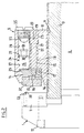
- FIG. 2 shows the device from FIG. 1 in a cross section,
- FIG. 3 shows the device from FIG. 1 in a longitudinal section,
- FIG. 4 shows the entire device of FIG. 3 on a reduced scale
- and Figure 5 shows the device in side view.
Die erfindungsgemässe Vorrichtung enthält im wesentlichen die feste Klemmbackenanordnung 1, die mit der Unterlage 2 verbunden ist und die verschiebbare Klemmbackenanordnung 3. Zwischen dem Futter 4 der festen Klemmbackenanordnung und einem beweglichen Kopf 5 der verschiebbaren Klemmbackenanordnung befindet sich ein Werkstück 6. Die Verschiebung der Klemmbackenanordnung 3, respektive das Spannen wird durch Druckluft ausgeführt, die in jeder Werkstatt vorhanden ist und deren Zuführung hier nicht eingezeichnet ist. Anstatt Druckluft kann irgendein hydraulisches System verwendet werden. Die Klemmbackenanordnung bewegt sich in für solche Stücke übliche spielfreie Führungen 7, wie zum Beispiel Schwalbenschwanzführungen oder als Rolltisch, deren einen Teil in der Unterlage 2 und dessen anderer Teil in der Trägerplatte 8 ausgeführt ist. Auf dieser Trägerplatte 8 ist eine Zahnplatte 9 befestigt, wie insbesondere aus Figur 2 hervorgeht.The device according to the invention essentially contains the
Auf der Zahnplatte 9 ist der Backenhalter 10 verstellbar angeordnet, dessen Unterseite ebenfalls eine Zahnung 11 aufweist, die derjenigen der Zahnplatte 9 entspricht. Durch die Zahnplatte 9 und dem mit der Zahnung 11 versehenen Backenhalter ist es möglich, die Lichtweite für die Werkstücke in einem sehr grossen Rahmen zu verändern. Nach dem Grobeinstellen des Abstandes zwischen dem Futter 4 und den Klemnköpfen 5 wird der Backenhalter auf der Zahnplatte mittels Schrauben befestigt.The
In Figur 2 ist ausserdem erkennbar, dass das Futter 4 mittels Schrauben 12 auswechselbar an der festen Klemmbacke 1 befestigbar ist. Im Futter 4 sind ferner Anschlagstifte 13 eingeschraubt, die eine bestimmte Einteilung gemäss einem gewünschten Rastermass erlauben.In Figure 2 it can also be seen that the
Der Aufbau des Backenhalters 10 mit den beweglichen Klemmköpfen 5 geht am besten aus den Figuren 2, 3 und 5 hervor. Der Backenhalter 10 hat eine Länge, die derjenigen der festen Klemmbackenanordnung 1 entspricht und enthält eine Anzahl von Klemmbacken 14 mit den beweglichen Klemmköpfen 5. In vorliegendem Beispiel gemäss Figur 4 sind es sechs Klemmbacken, doch ist es selbstverständlich, dass es sowohl weniger als auch mehr sein können, doch spielt die Anzahl für das Funktionsprinzip keine Rolle. Jede Klemmbacke 14 wird mittels zweier Führungsbolzen 15 geführt, dessen mit einem Gewinde versehener Kopf 16 in eine entsprechend mit einem Gewinde versehenen Bohrung 17 in der Klemmbacke verschraubt ist und der über eine Führungsbuchse 18 im Backenhalter 10 geführt ist und in einen Schraubenkopf 19 mündet, der mit einem Schlitz 20 oder dergleichen ausgestattet ist, um den Führungsbolzen verdrehen zu können, wobei das Kopfinnere auf einem Anschlag 21 aufliegt, der durch den Uebergang von der engeren Bohrung 22 zur weiteren Bohrung 23 gebildet wird. Aus der Anordnung der Führungsbolzen ist ersichtlich, dass diese beiden Führungsbolzen pro Klemmbacke nicht nur diese führen, sondern auch die Möglichkeit geben, durch Verdrehen der Führungsbolzen die Länge zwischen Kopf und Klemmbacke zu verstellen, d.h. den Anschlag zu verändern.The structure of the
Der Anschlag mittels den Führungsbolzenköpfen ist notwendig, da die Klemmbacken von einem Druckzylinder 24 beaufschlagt sind.The stop by means of the guide bolt heads is necessary because the clamping jaws are acted upon by a
Der Druckzylinder 24 greift mit seinem abgerundeten Kopf 25 etwa in der Höhe des Werkstückes und zwischen den beiden Führungsbolzen 15 am Klemmbacken an und sein zylindrischer Teil 26 ist in einer Bohrung 27 geführt, die in eine Bohrung 28 mit grösserem Durchmesser übergeht, so dass am Uebergang ein Anschlag 29 für den Kolbenring 30 entsteht. Der zylindrische Teil geht hinten in ein Griffteil 31 über. Das Druckmedium, beispielsweise Oel, ist in einem geschlossenen System enthalten, das aus einer durch den Backenhalter durchgehenden Querbohrung 33 und der weiteren Bohrung 28 für den Druckzylinder, bzw. Dichtungsring am Zylinder besteht. Die Querbohrung 33 wird durch zwei abgedichtete Schrauben 34 verschlossen, während die weitere Bohrung 28, in welcher sich der Druckzylinder befindet, durch eine Schraube 35 abgeschlossen ist. In Figur 4 ist schematisch dargestellt, dass dieses hydraulische System, womit jede Klemmbacke individuell unter Druck gesetzt ist, in der Lage ist, die Klemmbacken in einem gewissen, durch das Justieren der Führungsbolzen vorgegebenen Bereich individuell lateral zu verschieben und somit Werkstücken unterschiedlicher Breiten anzupassen. Der Füllungsgrad des hydraulischen Systems, bzw. der Weg der Führungsbolzen kann individuell über die Führungsbolzen eingestellt werden und richtet sich nach Erfahrungswerten und/oder nach den einzuspannenden Werkstücken.The
Im Prinzip wäre es möglich, bereits mit einem solchen Werkzeug mit individuell beaufschlagbaren Klemmbacken eine Anzahl von Werkstücken mit verschiedenen Dimensionen einzuspannen, wobei jedoch die einzuspannenden Flächen untereinander parallel sein müssten. Um jedoch auch Werkstücke einspannen zu können, deren Spannflächen nicht parallel zueinander stehen, sind Mittel vorgesehen, sich diesen nicht-parallelen Flächen anzupassen. Diese Mittel enthalten den beweglichen Klemmkopf 5, der in vorliegendem Ausführungsbeispiel in der horizontalen Ebene über einer bogenförmigen Schwalbenschwanz-Führung (siehe Figuren 2 und 3) 36 an der Klemmbacke 14 angeordnet ist. Der Klemmkopf weist, ebenso wie das feste Klemmbackenfutter 4, einen Absatz 37, bzw. 38 zur Aufnahme der Werkstücke auf. Die Funktion des beweglichen Klemmkopfes 5 geht am besten aus Figur 4 hervor, wobei insbesondere aus der Klemmbacke 14 d hervorgeht, dass damit nicht-parallele Werkstücke gespannt werden können. Sowohl die bewegliche Befestigung des Klemmkopfes an der Klemmbacke als auch dessen Klemmseite 39 können für unterschiedliche Werkstücke unterschiedlich gefertigt sein, abgesehen vom verwendeten Material, das in der Regel gehärteter Stahl oder dergleichen sein wird, aber in Ausnahmefällen auch aus Kunststoff bestehen kann, falls es sich um verletzliche Werkstücke handelt.In principle, it would be possible to clamp a number of workpieces with different dimensions with such a tool with clamping jaws that can be individually loaded, but the surfaces to be clamped would have to be parallel to one another. However, in order to also be able to clamp workpieces, their clamping surfaces are not parallel to each other, means are provided to adapt to these non-parallel surfaces. These means contain the
Um das Eindringen von Schmutz, bzw. Spänen und dergleichen zwischen die einzelnen Klemmbacken und Klemmköpfe zu verhindern, ist in den Zwischenräumen eine Kunststofflage 40 angeordnet, wobei der Kunststoff nachgiebig genug sein muss, um die Bewegungen der Elemente nicht zu behindern.In order to prevent the ingress of dirt or chips and the like between the individual clamping jaws and clamping heads, a
Wie aus der Beschreibung der beweglichen Klemmbacken-Anordnung hervorgeht, wird das eigentliche Spannen durch die Verschiebung der Trägerplatte mittels einem Druckmedium wie Druckluft oder Oel bewirkt, während die individuell verschiebbaren Klemmbacken für den Ausgleich der unterschiedlichen Dimensionen und Formen der Werkstücke besorgt sind. Wie bereits erwähnt, kann die Anzahl der Klemmbacken in einem grossen Umfang variieren, je nach dem Verwendungszweck der Vorrichtung.As can be seen from the description of the movable clamping jaw arrangement, the actual clamping is effected by moving the carrier plate by means of a pressure medium such as compressed air or oil, while the individually displaceable clamping jaws are used to compensate for the different dimensions and shapes of the workpieces. As already mentioned, the number of clamping jaws can vary widely, depending on the purpose of the device.
Ausserdem kann selbstverständlich auch die Grösse der Klemmbacken in einem grossen Umfang variieren. So können beispielsweise relativ kleine Klemmbacken für eine grosse Anzahl von kleinen Teilen, die gleichzeitig gespannt werden können, verwendet werden, oder eine geringere Anzahl grosser Klemmbacken für relativ grosse Werkstücke. Ausserdem muss nicht notwendigerweise ein einzelner Klemmkopf pro Klemmbacke verwendet werden. Es können auch mehrere gegliederte Klemmköpfe verwendet werden.In addition, the size of the jaws can of course vary to a large extent. For example, relatively small clamping jaws can be used for a large number of small parts that can be clamped at the same time, or a smaller number of large clamping jaws for relatively large workpieces. In addition, a single clamping head does not necessarily have to be used per clamping jaw. Several articulated clamping heads can also be used.
Wie insbesondere aus Figur 2 hervorgeht, kann auch die Breite des Werkstückes in einem grossen Umfange variieren, da der Backenhalter mit den einzelnen Klemmbacken auf der Zahnplatte 9 verschiebbar angeordnet ist, so dass die lichte Weite zwischen den Klemmbacken in einem sehr grossen Bereich verändert werden kann. Insbesondere aus Figur 2 geht hervor, dass die Trägerplatte 8, die dem Spannen der Werkstücke dient, stets nur eine kleine Verschiebebewegung ausführt.As can be seen in particular from Figure 2, the width of the workpiece can vary to a large extent, since the jaw holder with the individual clamping jaws is slidably arranged on the tooth plate 9, so that the clear width between the clamping jaws can be changed in a very large area . It can be seen in particular from FIG. 2 that the carrier plate 8, which is used to clamp the workpieces, always executes only a small displacement movement.
Während beim Ausführungsbeispiel gemäss den Figuren 1 bis 5 der Klemmbackenhalter mit dem beweglichen Klemmbacken als Teil der verschiebbaren Klemmbackenanordnung beschrieben und gezeichnet wurde, können die beweglichen Klemmbacken auch Teil der festen Klemmbackenanordnung sein und die verschiebbare Klemmbackenanordnung eine feste Klemmbackenleiste mit auswechselbarem Klemmfutter aufweisen. Diese wahlweise Anordnung wird dadurch erleichtert, dass der Klemmbackenhalter mit den beweglichen Klemmbacken ein geschlossenes Hydrauliksystem enthalten.While in the exemplary embodiment according to FIGS. 1 to 5 the jaw holder with the movable jaw was described and drawn as part of the displaceable jaw arrangement, the moveable jaws can also be part of the fixed jaw arrangement and the displaceable jaw arrangement has a fixed jaw strip with exchangeable clamping chuck. This optional arrangement is facilitated in that the jaw holder with the movable jaws contain a closed hydraulic system.
Im Ausführungsbeispiel der Figuren 1 - 5 wurde eine Spannvorrichtung für eine Bearbeitung oder eine Bearbeitungsfolge von Werkstücken in Bearbeitungsmaschinen beschrieben, doch lässt sich das Prinzip des Spannens mit mehreren individuell verschiebbaren Klemmbacken auch für das Heben von Werkstücken anwenden, bei welchen die Werkstücke in einer ganz bestimmten Lage positioniert sein müssen, um eine definierte Hubbewegung durchführen zu können. Dabei kann statt der Trägerplatte und der darauf montierten Zahnplatte eine andere Halterung für den Backenhalter verwendet werden.In the exemplary embodiment in FIGS. 1-5, a clamping device for processing or a processing sequence of workpieces in processing machines has been described, but the principle of clamping can be described Use with several individually movable clamping jaws for lifting workpieces, where the workpieces must be positioned in a very specific position in order to be able to carry out a defined lifting movement. Instead of the carrier plate and the tooth plate mounted on it, another holder for the jaw holder can be used.
Claims (8)
- Device for holding and clamping workpieces, comprising a fixed clamping jaw assembly (1) and one (3) which is displaceable relative thereto, one of said clamping jaw arrangements (1, 3) having at least two clamping jaws (14) and each of said clamping jaws having at least one displaceable clamping chuck and being under the action of a pressure cylinder (24), said pressure cylinders being connected to a closed hydraulic system, and said displaceable clamping jaw arrangement (3) being under the action of a second pressure medium, characterised in that the individual clamping jaws (14) are guided in a jaw holder (10) by means of guiding pins (15), each of said guiding pins having a threaded (16) head which is screwed into a corresponding bore (17) of said clamping jaw (14), the other end being terminated by a screw head (19) which is rotatable in a bore (23) of said jaw holder (10), and the middle portion being guided in a guide bush (18), the inner side of said screw head resting on a shoulder (21) which is formed in said bore (23) of said jaw holder (10).
- Device according to claim 1, characterised in that said closed hydraulic system is accommodated in said jaw holder (10) and comprises a through-going, sealable transversal bore (33) from which further bores (28) bifurcate which contain said pressure cylinders (24) and which communicate with narrower pressure bores (27), a respective shoulder (29) being formed at the transition which serves as an abutment for the sealing washer (30) of said pressure cylinders.
- Device according to claim 1 or 2, characterised in that the clamping head (5) is movably attached to said clamping jaw (14) by means of a curved dovetail guide (36).
- Device according to any one of claims 1 to 3, characterised in that said jaw holder (10) is displaceable and adjustable with respect to a base plate, the underside of said jaw holder (10) comprising a toothing (11) which cooperates with a corresponding toothing of a toothed plate (9) which is affixed to said base plate (8), and said jaw holder being attachable to said toothed plate by means of screws.
- Device according to claim 4, characterised in that said jaw holder (10) is fastened in the displaceable clamping jaw assembly (3), and said base plate (8) is under the action of a pressure medium.
- Device according to any one of claims 1 to 5, characterised in that the clamping jaw assembly (1, 3) which has no displaceable clamping jaws (14) comprises an exchangeable clamping chuck (4) which has a shoulder (38) for the reception of workpieces, a shoulder (37) of said clamping head (5) corresponding thereto.
- Device according to any one of claims 1 to 6, characterised in that said clamping chuck (4) comprises a number of bores intended to receive abutment pins (13).
- Device according to any one of claims 1 to 7, characterised in that a sealing joint (40) is provided between the individual clamping jaws (14a - f) and clamping heads (5).
Priority Applications (2)
| Application Number | Priority Date | Filing Date | Title |
|---|---|---|---|
| DE59106549T DE59106549D1 (en) | 1991-04-04 | 1991-04-04 | Device for holding and clamping workpieces. |
| EP19910810248 EP0507040B1 (en) | 1991-04-04 | 1991-04-04 | Workpieces holding and clamping device |
Applications Claiming Priority (1)
| Application Number | Priority Date | Filing Date | Title |
|---|---|---|---|
| EP19910810248 EP0507040B1 (en) | 1991-04-04 | 1991-04-04 | Workpieces holding and clamping device |
Publications (2)
| Publication Number | Publication Date |
|---|---|
| EP0507040A1 EP0507040A1 (en) | 1992-10-07 |
| EP0507040B1 true EP0507040B1 (en) | 1995-09-20 |
Family
ID=8208836
Family Applications (1)
| Application Number | Title | Priority Date | Filing Date |
|---|---|---|---|
| EP19910810248 Expired - Lifetime EP0507040B1 (en) | 1991-04-04 | 1991-04-04 | Workpieces holding and clamping device |
Country Status (2)
| Country | Link |
|---|---|
| EP (1) | EP0507040B1 (en) |
| DE (1) | DE59106549D1 (en) |
Cited By (1)
| Publication number | Priority date | Publication date | Assignee | Title |
|---|---|---|---|---|
| CN106944843A (en) * | 2017-03-14 | 2017-07-14 | 成都亨通兆业精密机械有限公司 | A kind of boring fastening localization method of special-shaped workpiece |
Families Citing this family (4)
| Publication number | Priority date | Publication date | Assignee | Title |
|---|---|---|---|---|
| US6345816B1 (en) | 2000-05-11 | 2002-02-12 | Snap Jaws Manufacturing Co. | Hydraulic vise jaws |
| DE10355555B4 (en) * | 2003-11-21 | 2012-08-09 | Hainbuch Gmbh Spannende Technik | Clamping jaws and clamping device for clamping workpieces |
| CN108161783A (en) * | 2017-12-29 | 2018-06-15 | 郑州速达煤炭机械服务股份有限公司 | A kind of multipurpose pressing device |
| CN117300686B (en) * | 2023-11-28 | 2024-02-20 | 山西昌鸿电力器材有限公司 | Auxiliary positioning device and positioning method for electric power fitting punching |
Family Cites Families (9)
| Publication number | Priority date | Publication date | Assignee | Title |
|---|---|---|---|---|
| DD16907U (en) * | ||||
| DE377706C (en) * | 1918-02-13 | 1923-06-25 | James Henry Jerrim | Vice for machine tools |
| US2411790A (en) * | 1943-10-22 | 1946-11-26 | Baron Cyril David Woolf | Workpiece holder |
| DE1920616U (en) * | 1961-01-13 | 1965-07-29 | Planeta Veb Druckmasch Werke | WORKPIECE CLAMP. |
| US4284267A (en) * | 1980-03-26 | 1981-08-18 | Dennis M. Thayer | Variable contour vice jaw |
| DE3201891A1 (en) * | 1981-03-12 | 1982-10-21 | Wilhelm 4322 Sprockhövel Vogelbruch | Hydraulic clamping device |
| DE3460885D1 (en) * | 1983-02-01 | 1986-11-13 | Roger Gloor | Accessory device for machine vices |
| GB8600321D0 (en) * | 1986-01-08 | 1986-02-12 | Yang T H | Design of clamping pincer |
| US4743003A (en) * | 1987-03-09 | 1988-05-10 | Dietlein Robert W | Ski vise with rotating jaws |
-
1991
- 1991-04-04 DE DE59106549T patent/DE59106549D1/en not_active Expired - Fee Related
- 1991-04-04 EP EP19910810248 patent/EP0507040B1/en not_active Expired - Lifetime
Cited By (1)
| Publication number | Priority date | Publication date | Assignee | Title |
|---|---|---|---|---|
| CN106944843A (en) * | 2017-03-14 | 2017-07-14 | 成都亨通兆业精密机械有限公司 | A kind of boring fastening localization method of special-shaped workpiece |
Also Published As
| Publication number | Publication date |
|---|---|
| DE59106549D1 (en) | 1995-10-26 |
| EP0507040A1 (en) | 1992-10-07 |
Similar Documents
| Publication | Publication Date | Title |
|---|---|---|
| EP1600254B1 (en) | Conveying unit for machine for working workpieces and method for machining such workpieces | |
| EP0473954A1 (en) | Clamping device for workpieces | |
| AT509260B1 (en) | MOVING AND POSITIONING DEVICE | |
| EP0507040B1 (en) | Workpieces holding and clamping device | |
| DE69607159T2 (en) | MULTIPURPOSE HEAD SHAPE AND FINISHING DEVICE | |
| DE2644287A1 (en) | WORKPIECE HOLDING AND FEEDING DEVICE | |
| DE1602602B2 (en) | FEED TABLE FOR LONGITUDINAL AND TRANSVERSAL MOVEMENT OF PLATE-SHAPED WORKPIECES ON A PUNCHING PRESS | |
| DE3135266C2 (en) | Cutting press for cutting out or separating parts from a workpiece sheet | |
| DE2731793C3 (en) | Device for machining the ends of teeth on gears | |
| EP0623420B1 (en) | Transporting and locating device | |
| DE3442011A1 (en) | Machine for the grinding machining of workpieces, in particular for the re-machining of tools | |
| DE3406367A1 (en) | Apparatus for transporting and machining plate-like workpieces | |
| EP0183117B1 (en) | Device for positioning work pieces on a supporting member | |
| DE1292994B (en) | Vertical, especially internal broaching machine | |
| DE9315813U1 (en) | Long bed machine for processing profiles | |
| DE3876017T2 (en) | CLEANING MACHINE. | |
| DE19920374C2 (en) | milling | |
| DE3518287C2 (en) | ||
| DE3420558A1 (en) | DRILLING MACHINE | |
| DE945887C (en) | Feeding device to chipping, trimming machines or the like for extremely short screw bolts | |
| DE20108188U1 (en) | Device for clamping workpieces, in particular window or door frame profiles | |
| EP0774322A1 (en) | Method of preparing a workpiece, in particular a brake calliper, for further treatment, as well as clamping device for carrying out the method | |
| DE9107104U1 (en) | Modular clamping device | |
| DE1728383C (en) | Clamping device for workpieces on a finger joint milling machine. Eliminated from: 1453268 | |
| DE4008819C2 (en) |
Legal Events
| Date | Code | Title | Description |
|---|---|---|---|
| PUAI | Public reference made under article 153(3) epc to a published international application that has entered the european phase |
Free format text: ORIGINAL CODE: 0009012 |
|
| AK | Designated contracting states |
Kind code of ref document: A1 Designated state(s): AT BE CH DE DK ES FR GB GR IT LI LU NL SE |
|
| 17P | Request for examination filed |
Effective date: 19930406 |
|
| 17Q | First examination report despatched |
Effective date: 19940419 |
|
| GRAA | (expected) grant |
Free format text: ORIGINAL CODE: 0009210 |
|
| AK | Designated contracting states |
Kind code of ref document: B1 Designated state(s): CH DE FR IT LI SE |
|
| PG25 | Lapsed in a contracting state [announced via postgrant information from national office to epo] |
Ref country code: IT Free format text: LAPSE BECAUSE OF FAILURE TO SUBMIT A TRANSLATION OF THE DESCRIPTION OR TO PAY THE FEE WITHIN THE PRE;WARNING: LAPSES OF ITALIAN PATENTS WITH EFFECTIVE DATE BEFORE 2007 MAY HAVE OCCURRED AT ANY TIME BEFORE 2007. THE CORRECT EFFECTIVE DATE MAY BE DIFFERENT FROM THE ONE RECORDED.SCRIBED TIME-LIMIT Effective date: 19950920 Ref country code: NL Free format text: LAPSE BECAUSE OF NON-PAYMENT OF DUE FEES Effective date: 19950920 Ref country code: FR Effective date: 19950920 Ref country code: GR Free format text: LAPSE BECAUSE OF FAILURE TO SUBMIT A TRANSLATION OF THE DESCRIPTION OR TO PAY THE FEE WITHIN THE PRESCRIBED TIME-LIMIT Effective date: 19950920 |
|
| REF | Corresponds to: |
Ref document number: 59106549 Country of ref document: DE Date of ref document: 19951026 |
|
| PG25 | Lapsed in a contracting state [announced via postgrant information from national office to epo] |
Ref country code: DK Free format text: LAPSE BECAUSE OF FAILURE TO SUBMIT A TRANSLATION OF THE DESCRIPTION OR TO PAY THE FEE WITHIN THE PRESCRIBED TIME-LIMIT Effective date: 19951220 Ref country code: SE Effective date: 19951220 |
|
| EN | Fr: translation not filed | ||
| PG25 | Lapsed in a contracting state [announced via postgrant information from national office to epo] |
Ref country code: AT Free format text: LAPSE BECAUSE OF NON-PAYMENT OF DUE FEES Effective date: 19960401 |
|
| PG25 | Lapsed in a contracting state [announced via postgrant information from national office to epo] |
Ref country code: LI Effective date: 19960430 Ref country code: CH Effective date: 19960430 |
|
| PGFP | Annual fee paid to national office [announced via postgrant information from national office to epo] |
Ref country code: LU Payment date: 19960430 Year of fee payment: 6 |
|
| PLBE | No opposition filed within time limit |
Free format text: ORIGINAL CODE: 0009261 |
|
| STAA | Information on the status of an ep patent application or granted ep patent |
Free format text: STATUS: NO OPPOSITION FILED WITHIN TIME LIMIT |
|
| 26N | No opposition filed | ||
| REG | Reference to a national code |
Ref country code: CH Ref legal event code: PL |
|
| PGFP | Annual fee paid to national office [announced via postgrant information from national office to epo] |
Ref country code: DE Payment date: 19961223 Year of fee payment: 6 |
|
| PG25 | Lapsed in a contracting state [announced via postgrant information from national office to epo] |
Ref country code: DE Free format text: LAPSE BECAUSE OF NON-PAYMENT OF DUE FEES Effective date: 19970430 |
|
| PG25 | Lapsed in a contracting state [announced via postgrant information from national office to epo] |
Ref country code: LU Free format text: LAPSE BECAUSE OF FAILURE TO SUBMIT A TRANSLATION OF THE DESCRIPTION OR TO PAY THE FEE WITHIN THE PRESCRIBED TIME-LIMIT Effective date: 19950920 |