EP0506919B1 - Motorisch angetriebener injektionskopf mit einer einrichtung zum messen des drehmoments - Google Patents
Motorisch angetriebener injektionskopf mit einer einrichtung zum messen des drehmoments Download PDFInfo
- Publication number
- EP0506919B1 EP0506919B1 EP91918502A EP91918502A EP0506919B1 EP 0506919 B1 EP0506919 B1 EP 0506919B1 EP 91918502 A EP91918502 A EP 91918502A EP 91918502 A EP91918502 A EP 91918502A EP 0506919 B1 EP0506919 B1 EP 0506919B1
- Authority
- EP
- European Patent Office
- Prior art keywords
- assembly
- dynamometric
- injection head
- motor
- measuring assembly
- Prior art date
- Legal status (The legal status is an assumption and is not a legal conclusion. Google has not performed a legal analysis and makes no representation as to the accuracy of the status listed.)
- Expired - Lifetime
Links
- 238000005259 measurement Methods 0.000 title description 7
- 238000002347 injection Methods 0.000 claims description 19
- 239000007924 injection Substances 0.000 claims description 19
- 230000006698 induction Effects 0.000 claims description 2
- 238000005553 drilling Methods 0.000 description 4
- 230000005540 biological transmission Effects 0.000 description 2
- 230000000712 assembly Effects 0.000 description 1
- 238000000429 assembly Methods 0.000 description 1
- 230000000295 complement effect Effects 0.000 description 1
- 230000003750 conditioning effect Effects 0.000 description 1
- 238000010276 construction Methods 0.000 description 1
- 239000011435 rock Substances 0.000 description 1
Images
Classifications
-
- E—FIXED CONSTRUCTIONS
- E21—EARTH OR ROCK DRILLING; MINING
- E21B—EARTH OR ROCK DRILLING; OBTAINING OIL, GAS, WATER, SOLUBLE OR MELTABLE MATERIALS OR A SLURRY OF MINERALS FROM WELLS
- E21B3/00—Rotary drilling
- E21B3/02—Surface drives for rotary drilling
- E21B3/022—Top drives
-
- E—FIXED CONSTRUCTIONS
- E21—EARTH OR ROCK DRILLING; MINING
- E21B—EARTH OR ROCK DRILLING; OBTAINING OIL, GAS, WATER, SOLUBLE OR MELTABLE MATERIALS OR A SLURRY OF MINERALS FROM WELLS
- E21B19/00—Handling rods, casings, tubes or the like outside the borehole, e.g. in the derrick; Apparatus for feeding the rods or cables
- E21B19/16—Connecting or disconnecting pipe couplings or joints
- E21B19/165—Control or monitoring arrangements therefor
- E21B19/166—Arrangements of torque limiters or torque indicators
-
- E—FIXED CONSTRUCTIONS
- E21—EARTH OR ROCK DRILLING; MINING
- E21B—EARTH OR ROCK DRILLING; OBTAINING OIL, GAS, WATER, SOLUBLE OR MELTABLE MATERIALS OR A SLURRY OF MINERALS FROM WELLS
- E21B47/00—Survey of boreholes or wells
- E21B47/007—Measuring stresses in a pipe string or casing
-
- E—FIXED CONSTRUCTIONS
- E21—EARTH OR ROCK DRILLING; MINING
- E21B—EARTH OR ROCK DRILLING; OBTAINING OIL, GAS, WATER, SOLUBLE OR MELTABLE MATERIALS OR A SLURRY OF MINERALS FROM WELLS
- E21B47/00—Survey of boreholes or wells
- E21B47/12—Means for transmitting measuring-signals or control signals from the well to the surface, or from the surface to the well, e.g. for logging while drilling
- E21B47/13—Means for transmitting measuring-signals or control signals from the well to the surface, or from the surface to the well, e.g. for logging while drilling by electromagnetic energy, e.g. radio frequency
Definitions
- the present invention relates to an injection head provided with a dynamometric measuring assembly and, more particularly to such an injection head intended to rotate a drill pipe.
- the first, and most classic, is the rotation table which is mounted on the floor of the drill mast and has a square or hexagonal opening intended to receive a drive rod of complementary section. The table is rotated and thus causes the rotation of the drill string.
- the other type of device is the motorized injection head, where an electric or hydraulic motor, mounted adjacent to the movable block, is connected directly to the upper end of the drill string.
- the motor is mounted on a carriage which slides on rails arranged vertically on the mast thus allowing the carriage to move while absorbing the torque generated during drilling.
- dynamometric measurement assemblies which are intended to be mounted on the drill string in order to be able to measure the forces and capture the various vibrations of the latter which are generated during drilling and which can be characteristic of either behavior of the drill string, either the state of wear of the tool, or the type of rock being destroyed.
- Document US-A-4,715,451 describes a drilling assembly comprising a motorized head and a drill rod element provided with a measuring assembly.
- the drill pipe member is disposed at the upper end of the drill string.
- the positioning of the dynamometric measuring assembly below the automatic key is a source of difficulty because, during certain maneuvers, for example the removal of only a few elements from the drill string while maintaining the circulation of the mud, first remove the measuring system. Additional time, resulting from this removal and reassembly of the measuring assembly, therefore adds to the maneuver.
- the object of the present invention is to overcome these drawbacks by proposing a motorized injection head provided with a dynamometric measuring assembly which is simple, reliable in construction and which makes it possible to carry out all types of maneuvers without dismantling the measuring assembly. .
- the invention proposes a motorized injection head, intended to drive in rotation a drill pipe, comprising a motor provided with a main shaft, an assembly of automatic key, an elevator and a dynamometric measurement assembly comprising at least one sensor, mounted on an extension of the main shaft, characterized in that the dynamometric measuring assembly is mounted adjacent to the engine outlet between the engine and the automatic key assembly.
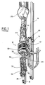
- FIG 1 a motorized injection head 10 fixedly mounted on a carriage 12 provided with rollers 14 which allow it to slide on two rails 16 arranged vertically and integral with the drilling mast (not shown).
- the injection head 10 comprises an engine 18 which can be electric or hydraulic and which comprises a hollow main shaft 20 which is connected by a bearing to a head injection 22 also fixedly mounted on the carriage 12. Conventionally, the injection head is suspended from the hook 24 of the movable block 26 which is part of the mast winch (not shown).
- the injection head 22 is supplied with mud, in a known manner, by a flexible conduit 28 connected to a source of pressurized mud (not shown). Below the motor 18, and connected thereto by torque transmission arms 30, are the automatic key assembly 32 and 34 of the elevator 36.
- the dynamometric measurement assembly 38 is disposed between the motor 18 and the automatic key assembly 32 and the elevator 36.
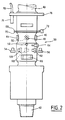
- the dynamometric measuring assembly represented at 38, comprises a hollow extension 40 of the main shaft 20 which comprises, at its lower end, a male thread 42 intended to cooperate with a female thread corresponding to the upper end of the drill string (not shown).
- the dynamometric measurement assembly 38 comprises a series of sensors mounted fixed on its outer surface and forming a measurement assembly.
- the assembly comprises two traction gauges 44 and 46, a pair 48, 50 of torsion gauges, a temperature gauge 52, a pair of longitudinal accelerometers 54, 56, and three transverse accelerometers 58, 60, 62.
- the assembly is provided with a pressure sensor 64.
- the data generated by the sensors are processed by an electronic conditioning circuit 66 which allows digital multiplexing of the signals.
- the electronic circuit is connected to a pair of annular tracks 68, 70 arranged around the shaft 40.
- a brush holder assembly 72 mounted in rotation relative to the shaft 40, is intended to pick up the signals from the annular tracks 68 , 70.
- This assembly 72 is connected to a connector 74 disposed on a flange 76 also mounted free to rotate on the shaft 40, the whole forming a rotating collector assembly.
- the signals are sent to a processing center distant from the drill mast by an ordinary transmission cable 78.
- the signals can be sent by radio or by magnetic induction.
- a sheath 80 is intended to be mounted on the flange 76 to protect the various sensors.
- a centralized measuring assembly is arranged integrally in the motorized injection head so as not to require additional maneuvering on the part of the driller.
Landscapes
- Engineering & Computer Science (AREA)
- Life Sciences & Earth Sciences (AREA)
- Geology (AREA)
- Mining & Mineral Resources (AREA)
- Physics & Mathematics (AREA)
- Geochemistry & Mineralogy (AREA)
- Environmental & Geological Engineering (AREA)
- Fluid Mechanics (AREA)
- General Life Sciences & Earth Sciences (AREA)
- Mechanical Engineering (AREA)
- Remote Sensing (AREA)
- Geophysics (AREA)
- Electromagnetism (AREA)
- Earth Drilling (AREA)
- Other Liquid Machine Or Engine Such As Wave Power Use (AREA)
- Turbine Rotor Nozzle Sealing (AREA)
- Steering Control In Accordance With Driving Conditions (AREA)
- Investigating Or Analyzing Materials By The Use Of Ultrasonic Waves (AREA)
- Magnetic Resonance Imaging Apparatus (AREA)
- Manufacture Of Motors, Generators (AREA)
- Lenses (AREA)
- Drilling And Boring (AREA)
- Testing Of Devices, Machine Parts, Or Other Structures Thereof (AREA)
- Force Measurement Appropriate To Specific Purposes (AREA)
- Testing Of Balance (AREA)
- Fluid-Pressure Circuits (AREA)
Claims (4)
- Motorisierter Spülkopf, der dazu bestimmt ist, eine Bohrstange in Drehung zu versetzen, welcher einen mit einer Hauptwelle (20) versehenen Motor (18), eine automatische Schlüsseleinheit (32), einen Elevator (36) und eine dynamometrische Meßeinheit (38) mit mindestens einem Meßfühler (44 bis 64) aufweist, dadurch gekennzeichnet, daß die dynamometrische Meßeinheit (38) auf einer Verlängerung der Hauptwelle (20) am Ausgang des Motors zwischen dem Motor (18) und der automatischen Schlüsseleinheit (32) angeordnet ist.
- Motorisierter Spülkopf nach Anspruch 1, dadurch gekennzeichnet, daß die Meßeinheit durch ein Kabel (78) mit einem Verarbeitungszentrum verbunden ist, wobei das Kabel (78) mit den Meßfühlern (44 bis 64) durch eine drehbare Kollektoreinheit verbunden ist.
- Motorisierter Spülkopf nach Anspruch 1, dadurch gekennzeichnet, daß die Meßeinheit durch Funk oder durch magnetische Induktion mit einem Verarbeitungszentrum verbunden ist.
- Motorisierter Spülkopf nach einem der Ansprüche 1 bis 3, dadurch gekennzeichnet, daß die Meßeinheit eine Torsionsmeßeinrichtung (48, 50), eine Traktionzmeßeinrichtung (44, 46) und Beschleunigungzmeßeinrichtungen (54 bis 62) aufweist.
Applications Claiming Priority (3)
| Application Number | Priority Date | Filing Date | Title |
|---|---|---|---|
| FR9012978 | 1990-10-19 | ||
| FR9012978A FR2668198B1 (fr) | 1990-10-19 | 1990-10-19 | Tete d'injection motorisee munie d'un ensemble de mesure dynamometrique. |
| PCT/FR1991/000812 WO1992007162A1 (fr) | 1990-10-19 | 1991-10-17 | Tete d'injection motorisee munie d'un ensemble de mesure dynamometrique |
Publications (2)
| Publication Number | Publication Date |
|---|---|
| EP0506919A1 EP0506919A1 (de) | 1992-10-07 |
| EP0506919B1 true EP0506919B1 (de) | 1995-04-19 |
Family
ID=9401405
Family Applications (1)
| Application Number | Title | Priority Date | Filing Date |
|---|---|---|---|
| EP91918502A Expired - Lifetime EP0506919B1 (de) | 1990-10-19 | 1991-10-17 | Motorisch angetriebener injektionskopf mit einer einrichtung zum messen des drehmoments |
Country Status (12)
| Country | Link |
|---|---|
| US (1) | US5272925A (de) |
| EP (1) | EP0506919B1 (de) |
| JP (1) | JP3019110B2 (de) |
| AT (1) | ATE121496T1 (de) |
| CA (1) | CA2071874C (de) |
| DE (1) | DE69109089T2 (de) |
| DK (1) | DK0506919T3 (de) |
| ES (1) | ES2073772T3 (de) |
| FR (1) | FR2668198B1 (de) |
| NO (1) | NO302308B1 (de) |
| OA (1) | OA09593A (de) |
| WO (1) | WO1992007162A1 (de) |
Families Citing this family (65)
| Publication number | Priority date | Publication date | Assignee | Title |
|---|---|---|---|---|
| US7100710B2 (en) | 1994-10-14 | 2006-09-05 | Weatherford/Lamb, Inc. | Methods and apparatus for cementing drill strings in place for one pass drilling and completion of oil and gas wells |
| US7108084B2 (en) | 1994-10-14 | 2006-09-19 | Weatherford/Lamb, Inc. | Methods and apparatus for cementing drill strings in place for one pass drilling and completion of oil and gas wells |
| US7228901B2 (en) | 1994-10-14 | 2007-06-12 | Weatherford/Lamb, Inc. | Method and apparatus for cementing drill strings in place for one pass drilling and completion of oil and gas wells |
| US7147068B2 (en) | 1994-10-14 | 2006-12-12 | Weatherford / Lamb, Inc. | Methods and apparatus for cementing drill strings in place for one pass drilling and completion of oil and gas wells |
| US6742596B2 (en) | 2001-05-17 | 2004-06-01 | Weatherford/Lamb, Inc. | Apparatus and methods for tubular makeup interlock |
| US7509722B2 (en) | 1997-09-02 | 2009-03-31 | Weatherford/Lamb, Inc. | Positioning and spinning device |
| US7140445B2 (en) | 1997-09-02 | 2006-11-28 | Weatherford/Lamb, Inc. | Method and apparatus for drilling with casing |
| US6536520B1 (en) * | 2000-04-17 | 2003-03-25 | Weatherford/Lamb, Inc. | Top drive casing system |
| GB9815809D0 (en) | 1998-07-22 | 1998-09-16 | Appleton Robert P | Casing running tool |
| GB2340858A (en) | 1998-08-24 | 2000-03-01 | Weatherford Lamb | Methods and apparatus for facilitating the connection of tubulars using a top drive |
| GB2340857A (en) | 1998-08-24 | 2000-03-01 | Weatherford Lamb | An apparatus for facilitating the connection of tubulars and alignment with a top drive |
| GB2340859A (en) | 1998-08-24 | 2000-03-01 | Weatherford Lamb | Method and apparatus for facilitating the connection of tubulars using a top drive |
| WO2000037766A2 (en) | 1998-12-22 | 2000-06-29 | Weatherford/Lamb, Inc. | Procedures and equipment for profiling and jointing of pipes |
| US7188687B2 (en) | 1998-12-22 | 2007-03-13 | Weatherford/Lamb, Inc. | Downhole filter |
| GB2347441B (en) | 1998-12-24 | 2003-03-05 | Weatherford Lamb | Apparatus and method for facilitating the connection of tubulars using a top drive |
| GB2345074A (en) | 1998-12-24 | 2000-06-28 | Weatherford Lamb | Floating joint to facilitate the connection of tubulars using a top drive |
| US6896075B2 (en) | 2002-10-11 | 2005-05-24 | Weatherford/Lamb, Inc. | Apparatus and methods for drilling with casing |
| US7311148B2 (en) | 1999-02-25 | 2007-12-25 | Weatherford/Lamb, Inc. | Methods and apparatus for wellbore construction and completion |
| US6857487B2 (en) | 2002-12-30 | 2005-02-22 | Weatherford/Lamb, Inc. | Drilling with concentric strings of casing |
| US6276466B1 (en) | 1999-10-29 | 2001-08-21 | Anthony R. Boyd | System for measuring the direction and revolution of a production string |
| US7216727B2 (en) | 1999-12-22 | 2007-05-15 | Weatherford/Lamb, Inc. | Drilling bit for drilling while running casing |
| US7334650B2 (en) | 2000-04-13 | 2008-02-26 | Weatherford/Lamb, Inc. | Apparatus and methods for drilling a wellbore using casing |
| US7325610B2 (en) | 2000-04-17 | 2008-02-05 | Weatherford/Lamb, Inc. | Methods and apparatus for handling and drilling with tubulars or casing |
| GB2365463B (en) | 2000-08-01 | 2005-02-16 | Renovus Ltd | Drilling method |
| EP1637695A1 (de) * | 2000-09-22 | 2006-03-22 | Weatherford/Lamb, Inc. | Verfahren und Vorrichtung zur Fernüberwachung und Steurerung. |
| US6994176B2 (en) | 2002-07-29 | 2006-02-07 | Weatherford/Lamb, Inc. | Adjustable rotating guides for spider or elevator |
| US6899186B2 (en) | 2002-12-13 | 2005-05-31 | Weatherford/Lamb, Inc. | Apparatus and method of drilling with casing |
| US7303022B2 (en) | 2002-10-11 | 2007-12-04 | Weatherford/Lamb, Inc. | Wired casing |
| US6832658B2 (en) * | 2002-10-11 | 2004-12-21 | Larry G. Keast | Top drive system |
| US7128154B2 (en) | 2003-01-30 | 2006-10-31 | Weatherford/Lamb, Inc. | Single-direction cementing plug |
| USRE42877E1 (en) | 2003-02-07 | 2011-11-01 | Weatherford/Lamb, Inc. | Methods and apparatus for wellbore construction and completion |
| US7360594B2 (en) | 2003-03-05 | 2008-04-22 | Weatherford/Lamb, Inc. | Drilling with casing latch |
| CA2517883C (en) | 2003-03-05 | 2010-01-12 | Weatherford/Lamb, Inc. | Full bore lined wellbores |
| CA2517895C (en) | 2003-03-05 | 2009-12-01 | Weatherford/Lamb, Inc. | Casing running and drilling system |
| US7874352B2 (en) | 2003-03-05 | 2011-01-25 | Weatherford/Lamb, Inc. | Apparatus for gripping a tubular on a drilling rig |
| US7503397B2 (en) | 2004-07-30 | 2009-03-17 | Weatherford/Lamb, Inc. | Apparatus and methods of setting and retrieving casing with drilling latch and bottom hole assembly |
| WO2004090279A1 (en) | 2003-04-04 | 2004-10-21 | Weatherford/Lamb, Inc. | Method and apparatus for handling wellbore tubulars |
| US7650944B1 (en) | 2003-07-11 | 2010-01-26 | Weatherford/Lamb, Inc. | Vessel for well intervention |
| US7264067B2 (en) | 2003-10-03 | 2007-09-04 | Weatherford/Lamb, Inc. | Method of drilling and completing multiple wellbores inside a single caisson |
| US7284617B2 (en) | 2004-05-20 | 2007-10-23 | Weatherford/Lamb, Inc. | Casing running head |
| DE602005006198T2 (de) | 2004-07-20 | 2009-07-09 | Weatherford/Lamb, Inc., Houston | Oberantrieb zur Verbindung von Futterrohren |
| CA2532907C (en) | 2005-01-12 | 2008-08-12 | Weatherford/Lamb, Inc. | One-position fill-up and circulating tool |
| CA2533115C (en) | 2005-01-18 | 2010-06-08 | Weatherford/Lamb, Inc. | Top drive torque booster |
| US20070030167A1 (en) * | 2005-08-04 | 2007-02-08 | Qiming Li | Surface communication apparatus and method for use with drill string telemetry |
| CA2586317C (en) * | 2006-04-27 | 2012-04-03 | Weatherford/Lamb, Inc. | Torque sub for use with top drive |
| GB2474375B (en) * | 2006-04-27 | 2011-06-08 | Weatherford Lamb | Torque sub for use with top drive |
| GB2478073B (en) * | 2006-04-27 | 2011-10-05 | Weatherford Lamb | Torque sub for use with top drive |
| US7882902B2 (en) | 2006-11-17 | 2011-02-08 | Weatherford/Lamb, Inc. | Top drive interlock |
| DK2288783T3 (en) * | 2008-04-25 | 2016-05-17 | Weatherford Technology Holdings Llc | METHOD FOR CONTROLLING TORQUE APPLICABLE a tubular CONNECTION |
| US8733454B2 (en) * | 2010-03-01 | 2014-05-27 | Frank's Casing Crew And Rental Tools, Inc. | Elevator grip assurance |
| US8631882B1 (en) * | 2010-12-07 | 2014-01-21 | Larry G. Keast | Drilling rig with torque measuring top drive |
| US8727039B1 (en) * | 2010-12-07 | 2014-05-20 | Larry G. Keast | Torque measuring top drive |
| US8726743B2 (en) | 2011-06-22 | 2014-05-20 | Weatherford/Lamb, Inc. | Shoulder yielding detection during tubular makeup |
| US10180061B2 (en) | 2011-09-26 | 2019-01-15 | Saudi Arabian Oil Company | Methods of evaluating rock properties while drilling using downhole acoustic sensors and a downhole broadband transmitting system |
| US9624768B2 (en) | 2011-09-26 | 2017-04-18 | Saudi Arabian Oil Company | Methods of evaluating rock properties while drilling using downhole acoustic sensors and telemetry system |
| US9903974B2 (en) | 2011-09-26 | 2018-02-27 | Saudi Arabian Oil Company | Apparatus, computer readable medium, and program code for evaluating rock properties while drilling using downhole acoustic sensors and telemetry system |
| US9074467B2 (en) * | 2011-09-26 | 2015-07-07 | Saudi Arabian Oil Company | Methods for evaluating rock properties while drilling using drilling rig-mounted acoustic sensors |
| US9234974B2 (en) | 2011-09-26 | 2016-01-12 | Saudi Arabian Oil Company | Apparatus for evaluating rock properties while drilling using drilling rig-mounted acoustic sensors |
| US9447681B2 (en) | 2011-09-26 | 2016-09-20 | Saudi Arabian Oil Company | Apparatus, program product, and methods of evaluating rock properties while drilling using downhole acoustic sensors and a downhole broadband transmitting system |
| US10551516B2 (en) | 2011-09-26 | 2020-02-04 | Saudi Arabian Oil Company | Apparatus and methods of evaluating rock properties while drilling using acoustic sensors installed in the drilling fluid circulation system of a drilling rig |
| US10107089B2 (en) * | 2013-12-24 | 2018-10-23 | Nabors Drilling Technologies Usa, Inc. | Top drive movement measurements system and method |
| US10370899B2 (en) | 2016-05-09 | 2019-08-06 | Nabros Drilling Technologies USA, Inc. | Mud saver valve measurement system and method |
| US10422450B2 (en) | 2017-02-03 | 2019-09-24 | Weatherford Technology Holdings, Llc | Autonomous connection evaluation and automated shoulder detection for tubular makeup |
| US10844675B2 (en) | 2018-12-21 | 2020-11-24 | Weatherford Technology Holdings, Llc | Autonomous connection makeup and evaluation |
| JP7706144B2 (ja) * | 2021-05-19 | 2025-07-11 | 三和機材株式会社 | 作業機 |
Family Cites Families (12)
| Publication number | Priority date | Publication date | Assignee | Title |
|---|---|---|---|---|
| US3876972A (en) * | 1972-06-19 | 1975-04-08 | Smith International | Kelly |
| US3855853A (en) * | 1973-05-09 | 1974-12-24 | Schlumberger Technology Corp | Well bore force-measuring apparatus |
| US3855857A (en) * | 1973-05-09 | 1974-12-24 | Schlumberger Technology Corp | Force-measuring apparatus for use in a well bore pipe string |
| US4285238A (en) * | 1978-04-25 | 1981-08-25 | Wilson Thomas E | Device for measuring lubricating oil temperature supplied to an internal combustion motorcycle engine |
| US4285236A (en) * | 1979-11-23 | 1981-08-25 | Dresser Industries, Inc. | Rotary torque and rpm indicator for oil well drilling rigs |
| US4449596A (en) * | 1982-08-03 | 1984-05-22 | Varco International, Inc. | Drilling of wells with top drive unit |
| US4715451A (en) * | 1986-09-17 | 1987-12-29 | Atlantic Richfield Company | Measuring drillstem loading and behavior |
| FR2608208B1 (fr) * | 1986-12-10 | 1989-04-07 | Sedco Forex Sa Services Techni | Procede de surveillance des operations de forage rotary d'un puits |
| US4811597A (en) * | 1988-06-08 | 1989-03-14 | Smith International, Inc. | Weight-on-bit and torque measuring apparatus |
| GB2228326B (en) * | 1988-12-03 | 1993-02-24 | Anadrill Int Sa | Method for determining the instantaneous rotation speed of a drill string |
| FR2642791A1 (fr) * | 1989-02-08 | 1990-08-10 | Soletanche | Dispositif de mesure de parametres de forage |
| US5182946A (en) * | 1991-11-08 | 1993-02-02 | Amerada Hess Corporation | Portable well analyzer |
-
1990
- 1990-10-19 FR FR9012978A patent/FR2668198B1/fr not_active Expired - Lifetime
-
1991
- 1991-10-17 DK DK91918502.5T patent/DK0506919T3/da active
- 1991-10-17 EP EP91918502A patent/EP0506919B1/de not_active Expired - Lifetime
- 1991-10-17 JP JP3517706A patent/JP3019110B2/ja not_active Expired - Lifetime
- 1991-10-17 US US07/861,781 patent/US5272925A/en not_active Expired - Lifetime
- 1991-10-17 AT AT91918502T patent/ATE121496T1/de not_active IP Right Cessation
- 1991-10-17 ES ES91918502T patent/ES2073772T3/es not_active Expired - Lifetime
- 1991-10-17 WO PCT/FR1991/000812 patent/WO1992007162A1/fr not_active Ceased
- 1991-10-17 CA CA002071874A patent/CA2071874C/fr not_active Expired - Lifetime
- 1991-10-17 DE DE69109089T patent/DE69109089T2/de not_active Expired - Fee Related
-
1992
- 1992-06-18 NO NO922400A patent/NO302308B1/no not_active IP Right Cessation
- 1992-06-19 OA OA60230A patent/OA09593A/fr unknown
Also Published As
| Publication number | Publication date |
|---|---|
| DK0506919T3 (da) | 1995-09-04 |
| DE69109089T2 (de) | 1995-10-26 |
| JP3019110B2 (ja) | 2000-03-13 |
| WO1992007162A1 (fr) | 1992-04-30 |
| NO302308B1 (no) | 1998-02-16 |
| NO922400L (no) | 1992-06-18 |
| OA09593A (fr) | 1993-04-30 |
| ATE121496T1 (de) | 1995-05-15 |
| JPH05503332A (ja) | 1993-06-03 |
| EP0506919A1 (de) | 1992-10-07 |
| DE69109089D1 (de) | 1995-05-24 |
| CA2071874C (fr) | 1997-10-07 |
| FR2668198B1 (fr) | 1997-01-10 |
| US5272925A (en) | 1993-12-28 |
| FR2668198A1 (fr) | 1992-04-24 |
| CA2071874A1 (fr) | 1992-04-20 |
| NO922400D0 (no) | 1992-06-18 |
| ES2073772T3 (es) | 1995-08-16 |
Similar Documents
| Publication | Publication Date | Title |
|---|---|---|
| EP0506919B1 (de) | Motorisch angetriebener injektionskopf mit einer einrichtung zum messen des drehmoments | |
| CA2035477C (fr) | Dispositif de mesure dynamometrique pour tige de forage | |
| CA1080190A (fr) | Methode et dispositif de rangement automatique d'un element allonge flexible dans un panier tournant d'axe vertical | |
| EP0100708A2 (de) | Verfahren und Gerät zur Sammlung von seismischen Signalen in einem Bohrloch | |
| WO2013144103A1 (fr) | Dispositif d'assistance à commande manuelle pour robot | |
| US5749397A (en) | Pipe tractor | |
| CA2354651A1 (fr) | Meuleuse de profils de rails | |
| FR2767153A1 (fr) | Dispositif et procede de centrage d'un outil dans un conduit notamment dans une tige de forage | |
| FR2642527A1 (fr) | Engin pour inspecter l'interieur des canalisations | |
| FR2526532A1 (fr) | Appareil pour le controle des tubes d'un echangeur de chaleur a une distance donnee de l'extremite de ces tubes | |
| FR2611804A1 (fr) | Procede de controle des operations de forage d'un puits | |
| FR2462696A1 (fr) | Dispositif de surveillance de la pression des pneumatiques d'un aerodyne | |
| FR2542297A1 (fr) | Dispositifs de mesure et d'indication pour treuils de tirage de cables | |
| FR2463256A1 (fr) | Outil de forage de fond et procede de forage d'un sondage au moyen de cet outil | |
| EP0528010B1 (de) | Vorrichtung zur messung der verschiebung eines kraftdrehkopfes eines bohrmastes | |
| FR2795804A1 (fr) | Dispositif pour le deplacement d'un organe dans un tube allonge depuis une extremite de ce tube | |
| FR2640314A1 (fr) | Ensemble de bobines de cable et de canalisation souple pour machine de forage | |
| CA2416275A1 (fr) | Motorisation d'un bracelet de mesure d'epaisseur d'un tuyau | |
| FR2712663A1 (fr) | Appareil d'inspection de l'état physique de canalisations non accessibles ou visitables par l'homme. | |
| FR2934148A1 (fr) | Brosse a dents cylindrique rotative a moteur electrique avec changement de sens de rotation automatique | |
| FR2602021A1 (fr) | Dispositif de transmission de couple bi-directionnelle | |
| WO1986001171A1 (fr) | Appareil pour l'observation et/ou le traitement d'une surface immergee | |
| EP0843050A1 (de) | Eine Bohrvorrichtung enthaltende Bohranlage | |
| EP0498876B1 (de) | Verfahren zur bestimmung der drehgeschwindigkeit eines bohrmeissels | |
| FR2753925A1 (fr) | Articulation oblique de robot |
Legal Events
| Date | Code | Title | Description |
|---|---|---|---|
| PUAI | Public reference made under article 153(3) epc to a published international application that has entered the european phase |
Free format text: ORIGINAL CODE: 0009012 |
|
| 17P | Request for examination filed |
Effective date: 19920619 |
|
| AK | Designated contracting states |
Kind code of ref document: A1 Designated state(s): AT BE CH DE DK ES FR GB GR IT LI LU NL SE |
|
| RAP1 | Party data changed (applicant data changed or rights of an application transferred) |
Owner name: ELF AQUITAINE PRODUCTION |
|
| 17Q | First examination report despatched |
Effective date: 19930721 |
|
| GRAA | (expected) grant |
Free format text: ORIGINAL CODE: 0009210 |
|
| AK | Designated contracting states |
Kind code of ref document: B1 Designated state(s): AT BE CH DE DK ES FR GB GR IT LI LU NL SE |
|
| PG25 | Lapsed in a contracting state [announced via postgrant information from national office to epo] |
Ref country code: AT Effective date: 19950419 Ref country code: GR Free format text: LAPSE BECAUSE OF FAILURE TO SUBMIT A TRANSLATION OF THE DESCRIPTION OR TO PAY THE FEE WITHIN THE PRESCRIBED TIME-LIMIT Effective date: 19950419 |
|
| REF | Corresponds to: |
Ref document number: 121496 Country of ref document: AT Date of ref document: 19950515 Kind code of ref document: T |
|
| REF | Corresponds to: |
Ref document number: 69109089 Country of ref document: DE Date of ref document: 19950524 |
|
| ITF | It: translation for a ep patent filed | ||
| PG25 | Lapsed in a contracting state [announced via postgrant information from national office to epo] |
Ref country code: SE Effective date: 19950719 |
|
| REG | Reference to a national code |
Ref country code: ES Ref legal event code: FG2A Ref document number: 2073772 Country of ref document: ES Kind code of ref document: T3 |
|
| GBT | Gb: translation of ep patent filed (gb section 77(6)(a)/1977) |
Effective date: 19950724 |
|
| REG | Reference to a national code |
Ref country code: DK Ref legal event code: T3 |
|
| PG25 | Lapsed in a contracting state [announced via postgrant information from national office to epo] |
Ref country code: LI Effective date: 19951031 Ref country code: LU Free format text: LAPSE BECAUSE OF NON-PAYMENT OF DUE FEES Effective date: 19951031 Ref country code: CH Effective date: 19951031 Ref country code: BE Effective date: 19951031 |
|
| PLBE | No opposition filed within time limit |
Free format text: ORIGINAL CODE: 0009261 |
|
| STAA | Information on the status of an ep patent application or granted ep patent |
Free format text: STATUS: NO OPPOSITION FILED WITHIN TIME LIMIT |
|
| 26N | No opposition filed | ||
| BERE | Be: lapsed |
Owner name: ELF AQUITAINE PRODUCTION Effective date: 19951031 |
|
| REG | Reference to a national code |
Ref country code: CH Ref legal event code: PL |
|
| REG | Reference to a national code |
Ref country code: CH Ref legal event code: AUV Free format text: LE BREVET CI-DESSUS EST TOMBE EN DECHEANCE, FAUTE DE PAIEMENT, DE LA 5E ANNUITE. |
|
| REG | Reference to a national code |
Ref country code: FR Ref legal event code: TP |
|
| PGFP | Annual fee paid to national office [announced via postgrant information from national office to epo] |
Ref country code: DK Payment date: 19980929 Year of fee payment: 8 |
|
| PGFP | Annual fee paid to national office [announced via postgrant information from national office to epo] |
Ref country code: ES Payment date: 19981019 Year of fee payment: 8 |
|
| PGFP | Annual fee paid to national office [announced via postgrant information from national office to epo] |
Ref country code: DE Payment date: 19981021 Year of fee payment: 8 |
|
| REG | Reference to a national code |
Ref country code: GB Ref legal event code: 732E |
|
| NLS | Nl: assignments of ep-patents |
Owner name: ELF EXPLORATION PRODUCTION |
|
| REG | Reference to a national code |
Ref country code: ES Ref legal event code: PC2A |
|
| PG25 | Lapsed in a contracting state [announced via postgrant information from national office to epo] |
Ref country code: DK Free format text: LAPSE BECAUSE OF NON-PAYMENT OF DUE FEES Effective date: 19991017 |
|
| PG25 | Lapsed in a contracting state [announced via postgrant information from national office to epo] |
Ref country code: ES Free format text: LAPSE BECAUSE OF NON-PAYMENT OF DUE FEES Effective date: 19991018 |
|
| REG | Reference to a national code |
Ref country code: DK Ref legal event code: EBP |
|
| PG25 | Lapsed in a contracting state [announced via postgrant information from national office to epo] |
Ref country code: DE Free format text: LAPSE BECAUSE OF NON-PAYMENT OF DUE FEES Effective date: 20000801 |
|
| REG | Reference to a national code |
Ref country code: GB Ref legal event code: IF02 |
|
| REG | Reference to a national code |
Ref country code: ES Ref legal event code: FD2A Effective date: 20001113 |
|
| PG25 | Lapsed in a contracting state [announced via postgrant information from national office to epo] |
Ref country code: IT Free format text: LAPSE BECAUSE OF NON-PAYMENT OF DUE FEES;WARNING: LAPSES OF ITALIAN PATENTS WITH EFFECTIVE DATE BEFORE 2007 MAY HAVE OCCURRED AT ANY TIME BEFORE 2007. THE CORRECT EFFECTIVE DATE MAY BE DIFFERENT FROM THE ONE RECORDED. Effective date: 20051017 |
|
| PGFP | Annual fee paid to national office [announced via postgrant information from national office to epo] |
Ref country code: GB Payment date: 20100928 Year of fee payment: 20 |
|
| PGFP | Annual fee paid to national office [announced via postgrant information from national office to epo] |
Ref country code: NL Payment date: 20100927 Year of fee payment: 20 Ref country code: FR Payment date: 20101115 Year of fee payment: 20 |
|
| REG | Reference to a national code |
Ref country code: NL Ref legal event code: V4 Effective date: 20111017 |
|
| REG | Reference to a national code |
Ref country code: GB Ref legal event code: PE20 Expiry date: 20111016 |
|
| PG25 | Lapsed in a contracting state [announced via postgrant information from national office to epo] |
Ref country code: NL Free format text: LAPSE BECAUSE OF EXPIRATION OF PROTECTION Effective date: 20111017 |
|
| PG25 | Lapsed in a contracting state [announced via postgrant information from national office to epo] |
Ref country code: GB Free format text: LAPSE BECAUSE OF EXPIRATION OF PROTECTION Effective date: 20111016 |