EP0506598A2 - Entwicklungsgerät - Google Patents
Entwicklungsgerät Download PDFInfo
- Publication number
- EP0506598A2 EP0506598A2 EP92500030A EP92500030A EP0506598A2 EP 0506598 A2 EP0506598 A2 EP 0506598A2 EP 92500030 A EP92500030 A EP 92500030A EP 92500030 A EP92500030 A EP 92500030A EP 0506598 A2 EP0506598 A2 EP 0506598A2
- Authority
- EP
- European Patent Office
- Prior art keywords
- tub
- rods
- developing
- processor
- developed
- Prior art date
- Legal status (The legal status is an assumption and is not a legal conclusion. Google has not performed a legal analysis and makes no representation as to the accuracy of the status listed.)
- Withdrawn
Links
Images
Classifications
-
- G—PHYSICS
- G03—PHOTOGRAPHY; CINEMATOGRAPHY; ANALOGOUS TECHNIQUES USING WAVES OTHER THAN OPTICAL WAVES; ELECTROGRAPHY; HOLOGRAPHY
- G03D—APPARATUS FOR PROCESSING EXPOSED PHOTOGRAPHIC MATERIALS; ACCESSORIES THEREFOR
- G03D3/00—Liquid processing apparatus involving immersion; Washing apparatus involving immersion
- G03D3/08—Liquid processing apparatus involving immersion; Washing apparatus involving immersion having progressive mechanical movement of exposed material
-
- G—PHYSICS
- G03—PHOTOGRAPHY; CINEMATOGRAPHY; ANALOGOUS TECHNIQUES USING WAVES OTHER THAN OPTICAL WAVES; ELECTROGRAPHY; HOLOGRAPHY
- G03D—APPARATUS FOR PROCESSING EXPOSED PHOTOGRAPHIC MATERIALS; ACCESSORIES THEREFOR
- G03D13/00—Processing apparatus or accessories therefor, not covered by groups G11B3/00 - G11B11/00
- G03D13/02—Containers; Holding-devices
- G03D13/04—Trays; Dishes; Tanks ; Drums
Definitions
- the invention deals with processors for developing photographic material equipped with a helicoidal spiral tub made up of independent tanks for liquids by having its central shaft arranged in a horizontal position inside a covering casing. A holder for the material to be developed, which is joined to and arm connected to a central shaft, has access to these tanks.
- a kind of processor of this type is known through the patent ES.P.8702521.
- each of the baths contained in the tanks is controlled by a series of external and internal water tanks, which keep the temperature even, for instance between 24 and 40 degrees.
- Each one of the baths is independent and each tank is occupied by the corresponding developing liquid and is communicated with the exterior through the tank filling and draining pipe.
- the objective of this invention is to make available a processor of the helicoidal spiral type, in which the tanks for material to be developed are operated from independent control units, which make sure that the capacity of the baths is maintained as well as keeping the temperature of the tanks perfect continuoulsy.
- Another object of the invention consists of creating a special carrying arm mounted on the central shaft of the machine, which allows the material to be developed to pass from one tank to the other with total ease.
- a third object of the invention consists of a material holder device with special characteristics, which is capable of transfering the material on plates or in the form of films, with sufficient loading capacity.
- a fourth and final object of the invention consists of taking advantage of the cover or casing of the processor to proceed with handling the material inside the machine without losing the characteristic of maintaining the appropriate darkness in its interior.
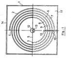
- a helicoidal spiral tub with its central shaft arranged in a horizontal direction is used.
- the rear side of the tub is closed whereas the front face is open starting from some semicircular walls which allow the independent tanks to be arranged.
- Each one of these tanks contains a developing bath and they are communicated with the exterior by means of rear pipes that pass through the control units.
- the centre of the tub receives a drive shaft that passes through the upper edges of the front semicircular walls, which also have semicircular hollows for this purpose and through which the said shaft runs.
- This shaft goes through the front section of the tub and is made up of two parallel metallic rods symmetrically arranged with regard to the theoretical axis of the tub. Both rods receive one of the arms of the holder or carrier which is made up of an L-shaped part, the other arm of which travels through the tanks in the tub.
- the holder must travel along the two rods of the shaft, so that the arm that carries the material to be developed can pass from one chamber to another with the said material.
- the said holder must be provided with extension capacity, in order to be able to adapt itself to the distance from the tub centre shaft to each one of the tanks of developing liquid.
- the arm of the holder that is connected to the two rods of the centre shaft is made up of a longitudinal plate with a rectangular cross-section and provided with a slot which is also longitudinal.
- a connection element is placed on the two sides of the longitudinal plate and inside the slot.
- connection element is composed of two discs placed in a parallel situation and between which the previously mentioned longitudinal plate becomes housed.
- the discs remain separated due to spacer shafts, for example three, of which two have bearings incorporated into them, with these bearings being housed inside the slot in the plate.
- the bearings and logically the shafts on which they are mounted, are arranged diametrically separated and horizontally aligned, in such a way that they travel along the slot.
- the discs are also provided with horizontal slots, four in each of them, in which small shafts are housed, with these shafts in turn having bearings incorporated.
- the bearings, four in each disc, are applied on the sides of the material holder plate above the slot, in order to make the rolling of the connection element easier.
- the rear disc of the two that the connection element is composed of is in turn connected with a cylindrical projection that juts out towards the two centre shaft rods.
- the cylindrical projection is provided with two parallel perforations which hold bearings inside them. These perforations receive the two rods from the centre shaft and, because of the bearings that are incorporated into them, make turning and transfer of this cylindrical projection on the rods easier, when the rods turn driven by the motor of the processor.
- connection element is made possible along the rods from the centre shaft, on which it can rotate, in such a way that the assembly also allows the grooved arm to be extended with the greatest of ease.
- the other arm of the holder is responsible for travelling through the tanks in the tub carrying the material to be developed, and is made up of a flattened body fitted with a lid of an equal cross-section.
- the body is provided with a series of pistons and the lid has holes that receive these pistons, with the material to be developed being held between them.
- Some of the holes in the lid have rounheaded nuts, which go through the holes in the lid by means of screw-threaded necks, in such a way that the lid can be fastened to the pistons in the body by means of the said nuts, with the material to be developed being held between them.
- Fitted onto the holder is an element which includes the material that has to be developed.
- This element is, precisely, the material holder and it is made up of two strips of articulated flexible material, arranged in a parallel fashion, between which is situated a flexible plate, for example made of plastic, which gives the assembly a certain rigidity.
- the side strips are formed by bands of strip made up of a series of single parts, made of rubber for example, in such a way that these units are connected to the next ones by means of a set of strips of the same material.
- Each group of strips is connected to another identical one thanks to corresponding recesses and projections cut at the ends of their outer edges.
- the ends of the strips are occupied by closure parts which make it easier for the material to be developed to enter and are connected to the other strips by means of recesses and projections that correspond with others at the end of the strip where they are placed.
- Each unit of the parts of the strip is symmetrical in relation to the opposite one situated at the other side of the flexible intermediate plate, and are provided with longitudinal recesses in their opposite faces. There are usually five of these recesses, with the central one being closed at its ends and receives, as will be seen later, some projections from the central flexible plate. The other four are open at both sides, so as to hold the plates or films to be developed.
- each one of the ends of each one is to be found with a wide open entrance that acts like a funnel for the material to be received.
- These funnelshaped areas are placed alternately on the four recesses for the purpose of making it easier to load the material to be developed.
- the end parts that close the strips are in their turn provided with the central recess and another four open ended ones, with funnel shaped areas at the outer ends of two of them and at the inner ends of the other two.
- the outer funnel shaped ends are very wide in order to help the initial entry of the material to be developed.
- the central flexible part is provided with longitudinal sides in which semicircular cut-outs have been made, regularly distributed, which form teeth between each two of them. These teeth are housed in the central recesses of the single parts of the strips, in such a way that they form the material holder unit with them.
- the material holder holds photographic paper of a certain dimension, which fits into the recesses in the single parts of the side strips.
- the material holder is adapted to receive rolls of film, which can occupy the recesses of single parts of the strips and wind themselves round the material holder.
- the roll is inserted through the end parts, starting its entry through one of their funnel shaped recesses so as to pass through the aligned recesses of the single parts of the strips, starting from their funnel shaped areas.
- the roll is inserted through one of the funnel shaped recesses of the other end parts and it returns to pass through another line of recesses, which have their funel shaped entrances arranged in the opposite direction.
- a roll of film can be arranged in its rolled-up form on the material holder in such a way that, due to the manner it fits into the recesses, sufficient space is established around the film to allow the developing liquids to circulate.
- Each tank with developing material is in contact, by means of tubular pipes, with a chamber, inside of which there is a heating element and a temperature probe which controls that each bath is to be found in the appropriate conditions.
- a volumetric probe connected to each developing tank, with which the amount of liquid in each tub is controlled.
- the chamber connected with each tub is also provided with holes in which pumps are connected for filling and draining the tanks, so that the baths can be properly controlled.
- This assembly is operated by means of a programme, according to which the filling, homogenizing and draining of the tanks are carried out automatically.
- the cabinet in which the processor is placed has a hinged cover at its front upper end.
- This cover or lid is shaped like a drawer, with an open front top, which on being turned against the front of the processor, occupies its intake.
- the opposite end of the cover or lid is occupied by a flexible sheet of a cloth type or similar, which is equipped with sleeves that allow the operator to insert his hands to handle items inside the processor.
- the centre shaft (12) driven by a programmed motor, with the two rods (13) responsible for receiving the holder and the element that moves the said holder.
- the upper part (14) of the processor receives a cover or lid similar to a drawer, which is not shown in this figure.
- Each tank is equipped with holes (10) so that they can be filled and drained.
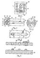
- the discs are provided with four openings in each of them, in which bearings (21) are also arranged, fitted to vertical shafts that pass through the openings.
- the arm (22) of the holder shown in figure 5 is taken in between the bearings (23) and (21), in such a way that the bearings (20) are housed in the central slot (25) and the bearings (21) act against the walls of the section (22), as illustrated in figure 3.
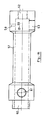
- Figure 5 represents the arm (24) of the holder, which is L-shaped, with its other arm (26), The longitudinal slot (25) that receives the bearings (20) can be observed and the upper and lower sections (22) on which the bearings (21) roll.
- the arm (24) is therefore perfectly controlled in its movements in relation to turning or rotating in either a vertical or a horizontal plane.
- the arm (24) is turned by the rods (13) of the processor centre shaft and the arm (26) travels with the material holder through the tanks (6), (7), (8)...
- the arm (24) begins to extend as the arm (26) occupies the tank (8) and turns towards the tanks (9), (6) and (7) ... in order to pass the material through the developing baths.
- the arm (24) becomes confronted by its end near the arm (26) with the front edges of the helicoidal spiral body.
- the loose cylinder (27) is placed, mounted on a window cut in the arm (24), in such a way that this cylinder turns over the said edges.
- the arm (26) of the holder which is represented in diagrammatic form in figure 6, shows a base section on which a series of projections or protrusions (27) stand out, and another section in the form of a lid or cover (28) provided which holes through which the abovementioned protrusions pass.
- a series of round headed nuts (30) are also arranged on this lid (27) which, with their necks threaded and fastened to the said lid, can be screwed onto the said protrusions (27).
- the material to be developed is situated between both, the arm (26) and the lid (28).
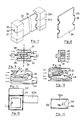
- the material holder that includes the photographic papers or rolls of film appears in a diagrammatic perspective in figure 7.
- This material holder is made up of a series of single or unitary parts (31) and (31a), which are symmetrical with relation to a central plane and are made up of flexible strips. The ends of these strips are finished by other parts (32) and (32a), which are connected to the said strips by means of an outer dovetail (33) joint.
- a flexible plate (34), figures 7 and 8, is situated, which gives body to the assembly to receive the photographic paper or roll (37) that is being dealt with.
- the flexible side strips are made up of parts (31) like the one illustrated in figures 9 and 10.
- parts (31) like the one illustrated in figures 9 and 10.
- recesses (38), (40), (41) and (39) which alternately have wide funnelshaped mouths or entrances towards one side or other of the part.
- recess (43) in which the projections or protrusions (36) of the flexible plate (34), figure 8, are housed.
- the parts (31) are connected to the adjoining ones by means of ribs (42), until groups are formed of several units identical to each other, which, thanks precisely to the ribs mentioned, conserve their flexibility.
- Each group of parts (31) is connected to other groups by means of a connection identical to the one indicated by (33) in figure 7.
- the parts (31a) opposite parts (31) are symmetrical with relation to a central plane of the plate (34), in such a way that from one end of the assembly which is so formed, a paper or a roll of film can be made to house in and along one row of recesses, for example (38), in accordance with the directions indicated in figure 9.
- the part shown in figure 12 corresponds to another part situated at the other end of a strip and another symmetrical part will correspond with it in relation to the flexible central plate.
- the assembly is ready to receive either photographic paper, by placing a plate of the appropriate dimensions, or roll or film by varying the width of the plate (34). In both cases, the teeth-like protrusions (36) of the plate will remain housed in the central recesses (43) of the parts.
- the number of recesses in the material holder can be varied at will to assume a greater or smaller number of them, according to requirements.
- FIG. 13 and 14 we can observe the outer body or casing (1) of the processor and above it the drawer-lid (52), articulated at its front forward area.
- This drawer-lid can be made to turn or pivot on its hinged area (14) so that it adopts the position (52a), thus closing the hollow or gap in the upper front part of the processing chamber.
- This drawer-lid (52) is provided with an open end (53) through which the said hollow or gap is occupied, and another end (54) opposite to the previous one, occupied by a sheath (55) equiped with some inlets or sleeves through which the operator can manipulate in the interior of the processor.
- the unit (57) is provided, and is reached by the inlet and outlet pipes (62) and (63) for the liquid that come from each tub, as well as another that communicates with the exterior (61).
- This unit is occupied by an electrical heating element at (60) and has one intake (58) for a temperature probe and another intake (59) for a volumetric probe. These probes are connected to a programming unit which keeps both variables according to what is planned.
Landscapes
- Physics & Mathematics (AREA)
- General Physics & Mathematics (AREA)
- Photographic Processing Devices Using Wet Methods (AREA)
- Photographic Developing Apparatuses (AREA)
Applications Claiming Priority (2)
| Application Number | Priority Date | Filing Date | Title |
|---|---|---|---|
| ES9100780A ES2029652A6 (es) | 1991-03-26 | 1991-03-26 | Procesadora de revelado. |
| ES9100780 | 1991-03-26 |
Publications (2)
| Publication Number | Publication Date |
|---|---|
| EP0506598A2 true EP0506598A2 (de) | 1992-09-30 |
| EP0506598A3 EP0506598A3 (en) | 1993-04-07 |
Family
ID=8271826
Family Applications (1)
| Application Number | Title | Priority Date | Filing Date |
|---|---|---|---|
| EP19920500030 Withdrawn EP0506598A3 (en) | 1991-03-26 | 1992-03-25 | Developing processor |
Country Status (4)
| Country | Link |
|---|---|
| US (1) | US5257059A (de) |
| EP (1) | EP0506598A3 (de) |
| JP (1) | JPH05113653A (de) |
| ES (1) | ES2029652A6 (de) |
Cited By (1)
| Publication number | Priority date | Publication date | Assignee | Title |
|---|---|---|---|---|
| EP0647883A1 (de) * | 1993-10-06 | 1995-04-12 | F.M. Control, S.L. | Entwicklungsverfahren und Gerät zu dessen Durchführung |
Families Citing this family (1)
| Publication number | Priority date | Publication date | Assignee | Title |
|---|---|---|---|---|
| US5614356A (en) * | 1994-06-08 | 1997-03-25 | Fuji Photo Film Co., Ltd. | Color developing agent, processing composition and color image-forming method |
Family Cites Families (5)
| Publication number | Priority date | Publication date | Assignee | Title |
|---|---|---|---|---|
| DE7133967U (de) * | 1971-09-07 | 1971-12-09 | Bockemuehl J | Traeger fuer zu behandelnde fotografische streifen wie filme |
| US4001856A (en) * | 1975-04-04 | 1977-01-04 | Stimson Paul B | Photographic processing apparatus |
| US4311380A (en) * | 1980-10-10 | 1982-01-19 | Dfp Enterprises | Automatic processor for dental x-ray film |
| DE8203539U1 (de) * | 1982-02-10 | 1982-07-22 | Agfa-Gevaert Ag, 5090 Leverkusen | Vorrichtung zur entwicklung farbfotografischer bilder |
| US4740074A (en) * | 1987-10-30 | 1988-04-26 | Powell Charles S | Film development system |
-
1991
- 1991-03-26 ES ES9100780A patent/ES2029652A6/es not_active Expired - Lifetime
-
1992
- 1992-03-25 EP EP19920500030 patent/EP0506598A3/en not_active Withdrawn
- 1992-03-25 US US07/857,155 patent/US5257059A/en not_active Expired - Fee Related
- 1992-03-26 JP JP4100343A patent/JPH05113653A/ja not_active Withdrawn
Cited By (1)
| Publication number | Priority date | Publication date | Assignee | Title |
|---|---|---|---|---|
| EP0647883A1 (de) * | 1993-10-06 | 1995-04-12 | F.M. Control, S.L. | Entwicklungsverfahren und Gerät zu dessen Durchführung |
Also Published As
| Publication number | Publication date |
|---|---|
| EP0506598A3 (en) | 1993-04-07 |
| JPH05113653A (ja) | 1993-05-07 |
| US5257059A (en) | 1993-10-26 |
| ES2029652A6 (es) | 1992-08-16 |
Similar Documents
| Publication | Publication Date | Title |
|---|---|---|
| US4922276A (en) | Continuous processing machine for photographic sheet material | |
| US2947236A (en) | Process and apparatus for the photographic liquid processing of coatings on flexiblesupports | |
| US4178088A (en) | Photographic processor | |
| US5257059A (en) | Developing processor | |
| US4032943A (en) | Dental x-ray film processing system | |
| US6508599B2 (en) | Multi-reaction chamber static film processor which allows for multiple overlapped-cycle film processing | |
| US3890629A (en) | Device for developing photographic film or paper | |
| FR2503401A1 (fr) | Appareil automatique pour developper des films photographiques ou similaires | |
| JPS5886543A (ja) | 柔軟な写真材料のシ−トを液で処理するための装置 | |
| US4248514A (en) | Photographic processing apparatus | |
| US3868715A (en) | System for chemical processing | |
| US4910546A (en) | Film processing device | |
| US3695162A (en) | Developing machine for photographic film | |
| EP0350875B1 (de) | Photographische Entwicklungseinheit | |
| US4054902A (en) | Apparatus for developing photographic prints | |
| US4634251A (en) | Apparatus for developing photographs and photographic strips | |
| US3550520A (en) | Device for automatic developing of photographic sensitive surfaces | |
| US2810572A (en) | Film processing apparatus | |
| CA1293405C (en) | Dental x-ray film developing machine | |
| US4152066A (en) | Apparatus for processing color prints | |
| EP0507406A2 (de) | Vorrichtung zur automatischen Entwicklung von Röntgenfilmen, fotografischen Filmen und dergleichen | |
| DE2802215A1 (de) | Einbadentwicklungsgeraet | |
| DE2115487B2 (de) | Tageslicht-Entwicklungsgerät | |
| US1140500A (en) | Photographic-film developing and fixing apparatus. | |
| US2286229A (en) | Portable film developing apparatus |
Legal Events
| Date | Code | Title | Description |
|---|---|---|---|
| PUAI | Public reference made under article 153(3) epc to a published international application that has entered the european phase |
Free format text: ORIGINAL CODE: 0009012 |
|
| AK | Designated contracting states |
Kind code of ref document: A2 Designated state(s): AT BE CH DE DK ES FR GB GR IT LI LU MC NL PT SE |
|
| PUAL | Search report despatched |
Free format text: ORIGINAL CODE: 0009013 |
|
| AK | Designated contracting states |
Kind code of ref document: A3 Designated state(s): AT BE CH DE DK ES FR GB GR IT LI LU MC NL PT SE |
|
| 18W | Application withdrawn |
Withdrawal date: 19940104 |