EP0506535A1 - Method and system for processing of pre-echos of a frequency transform coded digital audio signal - Google Patents
Method and system for processing of pre-echos of a frequency transform coded digital audio signal Download PDFInfo
- Publication number
- EP0506535A1 EP0506535A1 EP92400775A EP92400775A EP0506535A1 EP 0506535 A1 EP0506535 A1 EP 0506535A1 EP 92400775 A EP92400775 A EP 92400775A EP 92400775 A EP92400775 A EP 92400775A EP 0506535 A1 EP0506535 A1 EP 0506535A1
- Authority
- EP
- European Patent Office
- Prior art keywords
- module
- sample
- noise
- samples
- coding
- Prior art date
- Legal status (The legal status is an assumption and is not a legal conclusion. Google has not performed a legal analysis and makes no representation as to the accuracy of the status listed.)
- Granted
Links
- 238000000034 method Methods 0.000 title claims abstract description 57
- 238000002592 echocardiography Methods 0.000 title claims abstract description 28
- 238000012545 processing Methods 0.000 title claims abstract description 26
- 230000005236 sound signal Effects 0.000 title description 6
- 238000001914 filtration Methods 0.000 claims abstract description 59
- 230000007704 transition Effects 0.000 claims abstract description 50
- 230000005540 biological transmission Effects 0.000 claims abstract description 29
- 239000000654 additive Substances 0.000 claims abstract description 6
- 230000000996 additive effect Effects 0.000 claims abstract description 6
- 230000008569 process Effects 0.000 claims description 19
- 230000009466 transformation Effects 0.000 claims description 10
- 239000011159 matrix material Substances 0.000 claims description 9
- 230000002441 reversible effect Effects 0.000 claims description 7
- 230000003044 adaptive effect Effects 0.000 claims description 6
- 238000013139 quantization Methods 0.000 claims description 6
- 238000011002 quantification Methods 0.000 claims description 5
- 230000001373 regressive effect Effects 0.000 claims description 2
- 238000004364 calculation method Methods 0.000 description 10
- 230000009467 reduction Effects 0.000 description 8
- 238000001228 spectrum Methods 0.000 description 5
- 238000001514 detection method Methods 0.000 description 4
- 238000011156 evaluation Methods 0.000 description 4
- 238000010586 diagram Methods 0.000 description 3
- 230000002123 temporal effect Effects 0.000 description 3
- 230000015556 catabolic process Effects 0.000 description 2
- 238000004891 communication Methods 0.000 description 2
- 238000006731 degradation reaction Methods 0.000 description 2
- 238000000605 extraction Methods 0.000 description 2
- 230000006870 function Effects 0.000 description 2
- 230000000873 masking effect Effects 0.000 description 2
- 230000000694 effects Effects 0.000 description 1
- 230000006872 improvement Effects 0.000 description 1
- 230000004048 modification Effects 0.000 description 1
- 238000012986 modification Methods 0.000 description 1
- 238000005070 sampling Methods 0.000 description 1
- 238000007493 shaping process Methods 0.000 description 1
- 230000008054 signal transmission Effects 0.000 description 1
- 230000003595 spectral effect Effects 0.000 description 1
- 238000012546 transfer Methods 0.000 description 1
Images


Classifications
-
- H—ELECTRICITY
- H03—ELECTRONIC CIRCUITRY
- H03H—IMPEDANCE NETWORKS, e.g. RESONANT CIRCUITS; RESONATORS
- H03H17/00—Networks using digital techniques
- H03H17/02—Frequency selective networks
- H03H17/0248—Filters characterised by a particular frequency response or filtering method
- H03H17/0255—Filters based on statistics
- H03H17/0257—KALMAN filters
-
- H—ELECTRICITY
- H04—ELECTRIC COMMUNICATION TECHNIQUE
- H04B—TRANSMISSION
- H04B1/00—Details of transmission systems, not covered by a single one of groups H04B3/00 - H04B13/00; Details of transmission systems not characterised by the medium used for transmission
- H04B1/66—Details of transmission systems, not covered by a single one of groups H04B3/00 - H04B13/00; Details of transmission systems not characterised by the medium used for transmission for reducing bandwidth of signals; for improving efficiency of transmission
Definitions
- the invention relates to a method and a system for processing the pre-echoes of an audio-digital signal coded by frequency transform.
- the coding by transform proceeds by cutting up the time signal, succession of samples x (n), into blocks comprising N samples. On each of the aforementioned blocks, after application of a space-time amplitude weighting window, such as the window of block m on the samples 0 to N-1 as shown in FIG. La, these windows being reiterated with an overlap on N / 2 samples, a time / frequency transform is applied to the block of samples thus weighted, to obtain a set of coefficients y (k) which are then coded and then transmitted with the desired rate reduction.
- a space-time amplitude weighting window such as the window of block m on the samples 0 to N-1 as shown in FIG. La
- the coding noise resulting from the quantization of the coefficients is distributed uniformly over the duration of the sample block.
- this block contains a non-stationarity, such as a sudden attack, as shown in FIG. 1b, the frequency spectrum of the signal, that is to say the distribution of the amplitude of the coefficients y (k) obtained after frequency transform, as a function of frequency f is almost flat.
- the aforementioned coding algorithms generally perform a spectral shaping of the noise (cf. publication of Johnston aforementioned) and, even with respect to the block containing a transition, as mentioned previously, the noise spectrum is almost flat and a constant level for the entire duration of the block.
- the two blocks preceding the transition are affected by the phenomenon of N / 2 samples between successive windows. pre-echoes.
- the subject of the present invention is the implementation of a method and a system for processing the pre-echoes of an audio-digital signal coded by TCDM transform in which the pre-echoes are substantially suppressed.
- Another object of the present invention is the implementation of a method and a system for processing the pre-echoes of an audio-digital signal coded by TCDM transform in which no modification of the signal levels, before or after attack, not being carried out, a quasi-perfect reconstruction of the signal after decoding is thus obtained.
- the method for processing the pre-echoes of an audio-digital signal coded by frequency transform, object of the present invention is remarkable in that it consists, after coding of this signal x (n) by frequency transform into coefficients y (k), on weighting windows formed on blocks of samples comprising N samples x ( n) successive, to be performed when decoding the transform coefficients y (k), an optimal filtering so as to reduce, when there is a transition or amplitude variation of the signal, the additive noise resulting during the coding of the quantification of the transform coefficients.
- the system for processing the pre-echoes of filtering an audio-digital signal coded by frequency transform, object of the present invention comprising, on the one hand, arranged in cascade at the level of the coder a module for reading samples x ( n) of an audio-digital signal constituting the latter in blocks of N samples, a TCDM transform calculation module delivering, from said sample blocks, corresponding transform coefficients y (k) and a quantization coding module of these coefficients with a view to their transmission via a transmission channel, and, on the other hand, arranged in cascade at the level of the decoder, on reception of the transmission channel, a module for decoding the coefficients y (k ) and a module for calculating the inverse transform TCDM ⁇ 1, these modules constituting the decoder and delivering a noisy decoded signal x ′ (n), is remarkable in that it also comprises, on the one hand, at the level of the encoder, a module for detecting transitions identified by the rank Nq of the transition in
- the method and system which are the subject of the present invention find application in the transmission of audio-digital signals, of high fidelity quality, in the transmission, coding, decoding of audio-digital signals, in all the applications of signal transmission.
- audio-digital such as the integrated digital network of ISDN services.
- the method comprises steps of coding the digital audio signal x (n), these samples being, by a process of reading the samples conformed as a block, denoted x (n), these blocks comprising for example N successive samples , each block being subjected to a weighting window formed on these blocks, as shown for example in FIG.
- the above-mentioned blocks are then subjected to a TCDM transform processing, this transformation delivering the transform coefficients y (k).
- the aforementioned transform coefficients are then subjected to a coding process denoted H, this coding process delivering coded transform coefficients Cy (k) intended to be transmitted to and for a decoding process.
- the method which is the subject of the present invention consists in carrying out, at the decoding of the transform coefficients y (k), this decoding process being denoted H ⁇ 1 at the level of the decoding proper, and more particularly following an inverse transformation process noted TCDM ⁇ 1 applied to the transform coefficient y (k) to obtain the samples x ′ (n) of rank n of the noisy decoded signal, an optimal filtering of these samples of the noisy decoded signal so as to reduce, during the presence of an amplitude transition of the audio-digital signal, the additive noise resulting during the coding of the quantization of the transform coefficients.
- the presence of the pre-echoes at the level of the coded audio-digital signal is in fact due to the degradation of the signal preceding the transition by the introduction of an additive noise b (n) resulting from the quantification of the transform coefficients y (k).
- the treatment and reduction of this phenomenon in accordance with the object of the method according to the present invention, is comparable to a problem of denoising which can be carried out by means of an optimal filtering of the decoded audio-digital signal.
- the method which is the subject of the present invention generally involves, at the coding level, a process of identifying the transition.
- Such an identification can be carried out in a nonlimiting manner by the detection of such a transition in the current block considered, by the creation for example of a variable t representative of the existence or non-existence of such a transition in the aforementioned block.
- the identification of the transition in the current block considered may be carried out by discriminating the position of the transition in the aforementioned block, that is to say in fact from the abscissa M of the sample representative of the first occurrence of this transition.
- the method which is the subject of the present invention also involves the evaluation of an energy parameter of each of the samples x (n), this energy parameter for each of the samples x (n) of the aforementioned audio-digital signal being noted ⁇ 2x (n).
- a particularly advantageous implementation of the process which is the subject of the invention can be carried out taking into account the fact that the additive noise b (n) is not stationary. Indeed, the energy of the aforementioned noise is higher for n close to the transition in the block considered than for the samples located at the beginning of the block.
- a particularly advantageous implementation of the method which is the subject of the present invention consists in carrying out the optimal filtering previously mentioned in the form of a KALMAN filtering.
- the KALMAN filtering performed during decoding then makes it possible, in accordance with the method of the present invention, to obtain the reduction of the phenomenon of pre-echoes in a particularly satisfactory manner, as will be described below in the description.
- the state model is associated with the original signal x (n) while the observation equation describes the decoded signal x ′ (n) noisy, that is to say affected by the pre-echoes.
- the equation of state can be defined in self-regressive form of order p.
- the value of p must be chosen so as to ensure a compromise between sufficiently precise modeling of the series of samples of the audio-digital signal x (n) and a volume and a limited computational load to ensure compatible processing in real time.
- a1 and a2 denote the prediction coefficients of the filter and w (n) denotes the amplitude of the innovation noise for the sample x (n) of rank n considered.
- x (n) naturally designates the original audio-digital signal, that is to say the sample of current order n considered
- b (n) designates the amplitude of the coding noise or pre-echo for this same sample
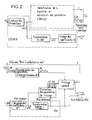
- x ′ (n) denotes the sample of rank n of the noisy decoded signal, that is to say the sample obtained on decoding, as shown in FIG. 2 after inverse transformation TCDM ⁇ 1.
- ⁇ 2b (n) denotes the energy of the coding noise and ⁇ 2w (n) the energy of the innovation noise w (n) for the sample x (n) of rank n considered.
- the method according to the invention then consists, during the coding process, in transmitting to the decoding level the value of the aforementioned energy parameters ⁇ 2x (n) and of the existence of the transition as described above.
- the method which is the subject of the present invention consists, during the decoding process, of estimating the filtering parameters, that is to say the prediction coefficients a1, a2 of the filtering from the samples of the block b-1 preceding, in accordance to the relationships previously given in the description.
- the energies of coding noise ⁇ 2b (n) and of noise ⁇ 2w (n) for the sample of rank n considered are evaluated, which makes it possible to ensure, at the decoding level, adaptive filtering of the KALMAN filtering type. of the noisy decoded signal x ′ (n) to reconstruct the filtered decoded signal in which the pre-echoes are substantially suppressed.
- t takes the value 0 or 1 as a function of the absence respectively of the presence of a transition for the current block considered.
- FIGS. 3a representing more particularly an encoder and 3b representing on the contrary a decoder constituting the system according to the invention.
- FIGS. 3a and 3b are shown in the form of block diagrams, the various block diagrams making it possible to carry out the steps of the method which is the subject of the present invention as carried out in FIG. 2.
- the system comprises, on the one hand, arranged in cascade at the level of the coder 1, a module 10 for reading samples x (n) of audio signal numerical constituting the latter as a block of N samples, a module 11 for calculating the TCDM transform delivering from the sample blocks the corresponding transform coefficients y (k) and a module 12 for coding by quantification of these coefficients with a view to their transmission via a digital transmission channel denoted CT in FIG. 3a.
- the digital transmission channel CT will not be described in detail since it corresponds to a transmission channel of the conventional type.
- the system according to the invention comprises, on the other hand, arranged in cascade at the level of the decoder 2 and on reception of the aforementioned transmission channel CT a decoding module 20 coefficients y (k) and a module 21 for calculating the inverse transform TCDM ⁇ 1, these modules constituting the decoder and delivering a noisy decoded signal x ′ (n).
- the system further comprises, at the level of the encoder 1, a module 13 for detecting the transitions identified by the rank Nq of the transition in the current block considered and a module 14 for extracting from the blocks of samples x (n) from the energy parameters ⁇ 2x (n) of the corresponding current x (n) sample or from a group of successive samples of the original signal.
- a coding module 15 is provided on the basis of the energy parameters ⁇ 2x (n) of the sample x (n) or of the group of samples of the sample block, this coding module making it possible to generate codes. corresponding C ⁇ 2x (n) and C, M in order to allow the coded transmission of the aforementioned parameters and of the signal indicator t of the presence of a transition in the current block via the transmission channel CT.
- transition detection module 13 As regards the previously mentioned transition detection module 13, it will simply be indicated that this generates the indicator t which, for example, takes the value 1 in the case of a block comprising a transition, that is to say say likely to generate pre-echoes, this indicator being simply coded on one bit and transmitted to the decoder.
- the module 13 also delivers the position of the transition in the block considered, that is to say the abscissa of the aforementioned point M.
- the address of the transition, M is then delivered to the coding module 15 previously mentioned and coded for example on log2 (N) bits where N is the size of the transform block for transmission in the form of the code C, M previously mentioned. .
- the detection of the attacks can be carried out by examination of the temporal waveform, for example comparison of the value of the amplitude of the sample considered with a threshold value in the report 4 previously mentioned, the module 13 detection of course receiving the samples x (n) of the block considered.
- the system according to the invention comprises at decoder level 2 a module 22 for reconstituting the energy parameters transmitted, this module receiving from the transmission channel CT the codes d transition address C, M and of energy C ⁇ 2x (n) and delivers the corresponding parameters of address M and energy ⁇ 2x (n). It will be noted that the module 22 makes it possible to reconstruct the parameters essential for filtering and which are unknown at the level of the decoder.
- a module 23 for extracting the filtering parameters a1, a2 is provided before carrying out the evaluation of these parameters from the samples x (n) of the preceding block of samples and d evaluation of the energies of the coding noise ⁇ 2b (n) and of the noise ⁇ 2w (n) for the sample of rank n considered.
- the extraction of the abovementioned filtering parameters can be carried out either from the noisy decoded signal x ′ (n) or from the quantized transform coefficients y ′ (k) delivered by the decoding module 20.
- a KALMAN filtering module 20 which receives the noisy decoded signal x ′ (n) as a filtering input delivered by the reverse transformation module 21 TCDM ⁇ 1, this same filtering module 24 receiving the parameters as command input. filtering a1, a2 and evaluating the energies of the coding noise ⁇ 2b (n) and of the noise ⁇ 2w (n) delivered by the module 23 for extracting the aforementioned parameters.
- the filter module 20 receives the reconstituted energy parameters delivered by the module 22 and of the address of the transition M.
- the filter module 20 outputs the filtered decoded signal xr (n).
- the decoder includes at the output a controlled switch 25 which receives, on the one hand, on a first switching input, the filtered decoded signal xr (n) and on a second switching input the signal x ′ (n) delivered by the decoder and more particularly by the reverse transformation module 21.
- the controlled switch 25 receives the indicator presence of transition t.
- the signal S delivered corresponds to that indicated in connection with FIG. 2.
- module 23 for extracting the filter parameters a1, a2 and for evaluating the coding noise energies ⁇ 2b (n) and the noise ⁇ 2w (n) will be given in connection with FIG. 4.
- the module 23 for extracting the above-mentioned filtering parameters comprises in parallel on an input port of the samples x ′ (n) of the noisy decoded signal a first channel A for calculating the filtering parameters a1 , a2 and noise ⁇ 2w (n) for the sample of rank n considered and a second channel B for calculating the coding noise ⁇ 2b (n).
- the filter parameters a1, a2 of the noise ⁇ 2w (n) and of the coding noise ⁇ 2b (n) are supplied to the filter module of KALMAN 24.
- the structure of the module 23 for extracting the filtering parameters as shown in FIG. 4a can be justified in the following manner.
- equation (1) requires knowledge of the prediction coefficients ai, i.e. a1, a2, when this equation of state is defined in self-regressive form of order 2 .
- the first channel A for calculating the filtering parameters comprises a sample memory 230 receiving the noisy samples x ′ (n) delivered by the module 21 for reverse transformation.
- the last R samples are kept in memory at the level of the memory 230.
- These R samples serve as input to the device for calculating the prediction coefficients.
- the first channel A consequently includes a circuit 231 for calculating the prediction coefficients ai or more precisely a1, a2 and the prediction gain Gp.
- the calculation circuit 231 can for example be constituted by a digital calculation circuit allowing the calculation of the above coefficients using a Levinson algorithm.
- the aforementioned Levinson algorithm will not be described since this algorithm is known from the state of the art.
- the prediction coefficients a1, a2 or more generally ai constitute one of the inputs of the filtering module 24. These coefficients are assumed to be constant over the duration of the pre-echo.
- the first channel A comprises in cascade with the circuit 231 for calculating the prediction and prediction gain coefficients Gp a circuit 232 for calculating the variance of the innovation noise ⁇ 2w (n).
- This circuit receives on the one hand the reconstituted value of the energy parameter of the sample ⁇ 2x ′ (n) transmitted delivered by the corresponding module 22 and the prediction gain Gp.
- ⁇ 2x (n) is the energy of the original noiseless audio-digital signal, G p representing the prediction gain associated with the autoregressive model.
- the calculation of the gain G p can be carried out at the level of the circuit 231 from the prediction coefficients a1 and a2 or more generally ai.
- a usable calculation method is described by Jayant and Noll in the Digital Coding of Waveforms 1984, Prentice Hall Signal Processing Series page 263.
- the second channel B comprises successively connected in cascade a circuit 233 for calculating the energy parameter ⁇ 2x ′ (n) of the sample x ′ (n) noisy.
- the calculation circuit 233 is followed by a circuit 235 for calculating the coding noise parameter ⁇ 2b (n) of the samples.
- the energy of the coding noise ⁇ 2b (n) can be deduced from the energies of the noiseless signals of origin ⁇ 2x (n) and of the noisy signal ⁇ 2x ′ (n) of the noisy signal x ′ (n).
- a is a constant between 0 and 1 and can for example be taken equal to 0.95.
- the calculation circuit 233 is associated with a delay circuit 234 which restores the value ⁇ 2x ′ (n-1) relative to the sample of order n-1 of the noisy signal x ′ (n-1).
- the circuit 233 for calculating the energy parameter ⁇ 2x ′ (n) then makes it possible to determine the current value of the energy of the noisy sample ⁇ 2x ′ (n) according to the relation 19.
- the value of the energy of the non-noisy sample ⁇ 2x (n) is, as we recall, calculated at the level of the coder, transmitted to the decoder and delivered by the corresponding circuit 22.
- ⁇ 2x (n) constant over the entire duration of the pre-echo so that only one corresponding value is transmitted per block of samples.
- the module 14 comprises a module 140 for cutting each block b of N samples into sub-blocks of a determined number of successive samples.
- the module 140 performs this cutting into a sub-block of dimension L.
- the value of the parameter L can be chosen so that local variations in energy can be isolated in a sub-block.
- the energy parameter ⁇ 2x (n) can be calculated by means of the relation:
- j represents the number of the sub-block among the set of M / L sub-blocks thus constituted, 0 ⁇ j ⁇ M / L-1.
- the abovementioned calculation is carried out by means of the module 141 for calculating the energy ⁇ 2x (j) which receives the various sub-blocks delivered by the module 140 previously described.
- the set [ ⁇ x2 (j)] of the energy parameters ⁇ 2x (j) is coded and transmitted to the decoder via the coding module 15.
- the coding of the abovementioned energy parameters can for example be carried out in accordance with the embodiment of this figure by quantification of the successive ratios.
- the coding module advantageously comprises successively a divider 150 receiving the energy parameters ⁇ 2x (j) previously described, a uniform quantizer 151 and a Huffmann coder 152.
- the output of the uniform quantizer 151 is further looped back to a input of the divider 150 via a reverse quantization circuit 153 followed by a sample delay circuit 154.
- the code words at the output of the uniform quantizer 151 can then undergo coding by entropy, for example, Huffmann coding by means of the coder 152.
- the coding module 15 then delivers the corresponding code C ⁇ 2x (n) for transmission by the transmission channel CT previously described.
- indices j, n are linked by the equation: j.L ⁇ n ⁇ (j + 1) .L-1.
- ⁇ 2x ′ (j) is the quantified version of ⁇ 2x (j) in subblock j received at the decoder and ⁇ 2x ′ (n) is estimated by equation (19) previously described.
- ⁇ 2b (n) ⁇ . ⁇ 2b (n-1) + (1- ⁇ ) ( ⁇ 2x ′ (n) - ⁇ 2x ′ (j))
- the first value ⁇ 2x (0) allowing the initialization of the recursive form given by the relation 20 must be coded with respect to a variable common to the decoder 1 and to the decoder 2.
- it may be the energy of the preceding block estimated by the sum of the energies of the quantized transform coefficients y ′ (k).
- the method and the system of the present invention make it possible to obtain particularly remarkable results because they make it possible to obtain a strong reduction in the pre-echoes.
- the original signal of a guitar attack sampled at 32 KHz over a duration of 32 msec is represented respectively in I.
- the amplitude axis is graduated in relative amplitude value which makes it possible to note, at the level of the samples immediately prior to the transition proper, a large variation in amplitude compared to the samples of the same block at the start of it. .
- the coded signal is shown without processing of the pre-echoes, the coding being carried out by means of a TCDM transform and the transmission being carried out with a bit rate of 64Kb / s.
- the phenomenon of pre-echoes is very apparent, insofar as the pre-echo noise, on the same samples immediately prior to the transition itself, presents a substantially peak-to-peak amplitude 4 to 5 times greater than the amplitude of the noise level of the samples present at the start of the corresponding block.
- the reduction in the level of the pre-echoes is particularly effective for any type of signal.
- the resulting improvement in quality is particularly noticeable especially when the coder uses a TCDM transform without there being a significant increase in the delay of the coding system.
- the processing, both at the level of the coding and at the level of the decoding is carried out in real time the transmission of the denoised samples being thus carried out in real time with the time of transmission and processing of a block close.
Abstract
Description
L'invention est relative à un procédé et à un système de traitement des prééchos d'un signal audio-numérique codé par transformée fréquentielle.The invention relates to a method and a system for processing the pre-echoes of an audio-digital signal coded by frequency transform.
Les processus de stockage, de transmission ou de traitement des signaux sonores numérisés, de plus en plus utilisés de nos jours, se heurtent au problème du débit numérique nécessaire toujours plus important selon les applications envisagées.The processes of storage, transmission or processing of digital sound signals, which are increasingly used today, face the problem of the necessary digital bit rate, which is increasingly important depending on the applications envisaged.
Des techniques très élaborées, telles que le codage de ces signaux par transformée fréquentielle, telle'que transformée en cosinus discrète modifiée, TCDM, sont utilisées afin de diminuer le débit d'information résultant, tout en conservant sensiblement la qualité du signal d'origine. Ainsi qu'on l'a représenté de manière illustrative en figure la, le codage par transformée procède par découpage du signal temporel, succession d'échantillons x(n), en blocs comportant N échantillons. Sur chacun des blocs précités, après application d'une fenêtre de pondération spatio-temporelle d'amplitude, telle que la fenêtre du bloc m sur les échantillons 0 à N-1 ainsi que représenté en figure la, ces fenêtres étant réitérées avec un recouvrement sur N/2 échantillons, une transformée temps/fréquence est appliquée au bloc d'échantillons ainsi pondérés, pour obtenir un ensemble de coefficients y(k) lesquels sont alors codés puis transmis avec la réduction de débit recherchée.Very sophisticated techniques, such as the coding of these signals by frequency transform, such as transformed into modified discrete cosine, TCDM, are used in order to decrease the resulting bit rate of information, while preserving appreciably the quality of the original signal . As illustrated in FIG. 1a, the coding by transform proceeds by cutting up the time signal, succession of samples x (n), into blocks comprising N samples. On each of the aforementioned blocks, after application of a space-time amplitude weighting window, such as the window of block m on the
Au décodage, une transformation inverse est appliquée aux coefficients reçus y′(k), ce qui permet de régénérer les échantillons d'origine x′(n) en temps réel, au temps de traitement codage-décodage, temps de transmission près. On notera toutefois que plusieurs types de transformées fréquentielles peuvent être utilisées, la transformée TCDM permettant cependant d'obtenir la réduction de débit la plus importante. Pour une description plus détaillée de ce type de traitement, on pourra se reporter par exemple aux publications de Johnston "Transfer Coding of Audio Singals Using Perceptual Noise Criteria" IEEE Journal on selected Areas in Communications, Vol. 6, No2, Février 1988, p. 314-323 et de Princen et Bradley "Adaptive Transform Coding incorporating Time Domain Aliasing Cancellation" Speech communication, Décembre 1987.During decoding, an inverse transformation is applied to the coefficients received y ′ (k), which makes it possible to regenerate the original samples x ′ (n) in real time, to the coding-decoding processing time, except for transmission time. Note however that several types of frequency transforms can be used, the TCDM transform making it possible however to obtain the greatest reduction in flow. For a more detailed description of this type of processing, see for example Johnston's publications "Transfer Coding of Audio Singals Using Perceptual Noise Criteria" IEEE Journal on selected Areas in Communications, Vol. 6, No2, February 1988, p. 314-323 and Princen and Bradley "Adaptive Transform Coding incorporating Time Domain Aliasing Cancellation" Speech communication, December 1987.
Dans les systèmes de codage par transformée fréquentielle, le bruit de codage résultant de la quantification des coefficients est réparti uniformément sur toute la durée du bloc d'échantillons.In frequency transform coding systems, the coding noise resulting from the quantization of the coefficients is distributed uniformly over the duration of the sample block.
Lorsque ce bloc contient une non stationnarité, telle qu'une attaque brusque, ainsi que représenté' en figure 1b, le spectre fréquentiel du signal, c'est-à-dire la distribution de l'amplitude des coefficients y(k) obtenus après transformée fréquentielle, en fonction de la fréquence f est à peu près plat.When this block contains a non-stationarity, such as a sudden attack, as shown in FIG. 1b, the frequency spectrum of the signal, that is to say the distribution of the amplitude of the coefficients y (k) obtained after frequency transform, as a function of frequency f is almost flat.
En outre, les algorithmes de codage précités réalisent généralement une mise en forme spectrale du bruit (cf. publication de Johnston précitée) et, même relativement au bloc contenant une transition, telle que mentionnée précédemment, le spectre du bruit est à peu près plat et d'un niveau constant pour toute la durée du bloc.In addition, the aforementioned coding algorithms generally perform a spectral shaping of the noise (cf. publication of Johnston aforementioned) and, even with respect to the block containing a transition, as mentioned previously, the noise spectrum is almost flat and a constant level for the entire duration of the block.
En conséquence, pour la partie précédant l'attaque, le spectre du bruit est bien supérieur à celui du signal. Ceci se traduit dans le domaine temporel, ainsi que représenté en figure 1c et 1d relatives à un signal original x(n) d'une attaque vibraphone respectivement à un signal correspondant décodé puis soumis à transformée inverse x′(n), par l'apparition d'une dégradation très importante appelée préécho.Consequently, for the part preceding the attack, the noise spectrum is much higher than that of the signal. This is reflected in the time domain, as represented in FIG. 1c and 1d relating to an original signal x (n) of a vibraphone attack respectively to a corresponding signal decoded then subjected to inverse transform x ′ (n), by the appearance of a very significant degradation called preecho.
En outre, lorsque le système de codage utilise la transformée TCDM, les deux blocs précédant la transition sont, du fait du recouvrement de N/2 échantillons entre fenêtres successives, affectés par le phénomène de prééchos.In addition, when the coding system uses the TCDM transform, the two blocks preceding the transition are affected by the phenomenon of N / 2 samples between successive windows. pre-echoes.
Différentes méthodes de traitement ont été proposées pour réduire ou éliminer le phénomène de prééchos.Different treatment methods have been proposed to reduce or eliminate the phenomenon of pre-echoes.
Parmi celles-ci on peut citer la méthode préconisée par Schroeder décrite dans l'article intitulé "Stereo Coding with CD quality" International Conference on Consumer Electronics, Chicago 1987 et par Sugiyama décrite dans l'article "Adaptive Transform Coding with an adaptive Block Size", Proceedings of ICASSP 90, Albuquerque p 1093 - 1096. Dans la méthode précitée, un facteur d'échelle est appliqué au bloc d'échantillons avant la transformation, de façon à réduire la différence de niveau avant et après la transition engendrée par l'attaque. L'application des facteurs d'échelle inverses au décodage permet de réduire le niveau de bruit dans les zones de faible énergie et donc l'amplitude, d'où la diminution correspondante du phénomène de préécho. Cependant une telle méthode ne peut être valablement utilisée lorsque la transformée fréquentielle est une transformée TCDM, une reconstitution parfaite du signal, en l'absence de codage, ne pouvant être effectuée, du fait de la présence même des facteurs d'échelle.Among these we can cite the method recommended by Schroeder described in the article entitled "Stereo Coding with CD quality" International Conference on Consumer Electronics, Chicago 1987 and by Sugiyama described in the article "Adaptive Transform Coding with an adaptive Block Size ", Proceedings of ICASSP 90, Albuquerque p 1093 - 1096. In the above method, a scale factor is applied to the sample block before the transformation, so as to reduce the level difference before and after the transition generated by l 'attack. The application of the inverse scale factors to the decoding makes it possible to reduce the noise level in the areas of low energy and therefore the amplitude, hence the corresponding reduction in the preecho phenomenon. However, such a method cannot be validly used when the frequency transform is a TCDM transform, a perfect reconstruction of the signal, in the absence of coding, which cannot be carried out, due to the very presence of the scaling factors.
La présente invention a pour objet la mise en oeuvre d'un procédé et d'un système de traitement des prééchos d'un signal audio-numérique codé par transformée TCDM dans lesquels les prééchos sont sensiblement supprimés.The subject of the present invention is the implementation of a method and a system for processing the pre-echoes of an audio-digital signal coded by TCDM transform in which the pre-echoes are substantially suppressed.
Un autre objet de la présente invention est la mise en oeuvre d'un procédé et d'un système de traitement des prééchos d'un signal audio-numérique codé par transformée TCDM dans lesquels aucune modification des niveaux de signal, avant ou après attaque, n'étant effectuée, une reconstitution quasi-parfaite du signal après décodage est ainsi obtenue.Another object of the present invention is the implementation of a method and a system for processing the pre-echoes of an audio-digital signal coded by TCDM transform in which no modification of the signal levels, before or after attack, not being carried out, a quasi-perfect reconstruction of the signal after decoding is thus obtained.
Le procédé de traitement des prééchos d'un signal audio-numérique codé par transformée fréquentielle, objet de la présente invention, est remarquable en ce qu'il consiste, après codage de ce signal x(n) par tranformée fréquentielle en coefficients y(k), sur des fenêtres de pondération formées sur des blocs d'échantillons comportant N échantillons x(n) successifs, à effectuer au décodage des coefficients de transformée y(k), un filtrage optimal de façon à réduire, lors de la présence d'une transition ou variation d'amplitude du signal, le bruit additif résultant lors du codage de la quantification des coefficients de transformée.The method for processing the pre-echoes of an audio-digital signal coded by frequency transform, object of the present invention is remarkable in that it consists, after coding of this signal x (n) by frequency transform into coefficients y (k), on weighting windows formed on blocks of samples comprising N samples x ( n) successive, to be performed when decoding the transform coefficients y (k), an optimal filtering so as to reduce, when there is a transition or amplitude variation of the signal, the additive noise resulting during the coding of the quantification of the transform coefficients.
Le système de traitement des prééchos de filtrage d'un signal audio-numérique codé par transformée fréquentielle, objet de la présente invention, ce système comportant, d'une part, disposés en cascade au niveau du codeur un module de lecture des échantillons x(n) de signal audio-numérique constituant ces derniers en blocs de N échantillons, un module de calcul de la transformée TCDM délivrant, à partir desdits blocs d'échantillons, des coefficients de transformée y(k) correspondants et un module de codage par quantification de ces coefficients en vue de leur transmission par l'intermédiaire d'un canal de transmission, et, d'autre part, disposés en cascade au niveau du décodeur, en réception du canal de transmission, un module de décodage des coefficients y(k) et un module de calcul de la transformée inverse TCDM⁻¹, ces modules constituant le décodeur et délivrant un signal décodé bruité x′(n), est remarquable en ce qu'il comporte en outre, d'une part, au niveau du codeur, un module de détection de transitions repérées par le rang N-q de la transition dans le bloc courant considéré, un module d'extraction, à partir des blocs d'échantillons x(n), des paramètres d'énergie σ²x(n) de l'échantillon x(n) ou d'un groupe d'échantillons successifs du signal d'origine, un module de codage, à partir des paramètres d'énergie σ²x(n) de l'échantillon x(n) ou du groupe d'échantillons du bloc d'échantillons, permettant la transmission codée des paramètres d'énergie σ²x(n), et d'un signal indicateur de la présence d'une transition dans le bloc d'échantillons considéré, et, d'autre part, au niveau du décodeur, un module de reconstitution de paramètres d'énergie σ²x(n) transmis, un module d'extraction des paramètres de filtrage a1, a2 à partir des échantillons x(n) du bloc précédent b-1 et d'évaluation des énergies du bruit de codage σ²b(n) et du bruit σ²w(n) pour l'échantillon de rang n considéré, un module de filtrage de Kalman recevant en entrée de filtrage le signal décodé bruité x′(n) et en entrée de commande lesdits paramètres de filtrage a1, a2 et l'évaluation des énergies du bruit de codage σ²w(n), ledit module de filtrage délivrant en sortie le signal décodé filtré xr(n).The system for processing the pre-echoes of filtering an audio-digital signal coded by frequency transform, object of the present invention, this system comprising, on the one hand, arranged in cascade at the level of the coder a module for reading samples x ( n) of an audio-digital signal constituting the latter in blocks of N samples, a TCDM transform calculation module delivering, from said sample blocks, corresponding transform coefficients y (k) and a quantization coding module of these coefficients with a view to their transmission via a transmission channel, and, on the other hand, arranged in cascade at the level of the decoder, on reception of the transmission channel, a module for decoding the coefficients y (k ) and a module for calculating the inverse transform TCDM⁻¹, these modules constituting the decoder and delivering a noisy decoded signal x ′ (n), is remarkable in that it also comprises, on the one hand, at the level of the encoder, a module for detecting transitions identified by the rank Nq of the transition in the current block considered, a module for extracting, from the blocks of samples x (n), energy parameters σ²x ( n) of the sample x (n) or of a group of successive samples of the original signal, a coding module, from the energy parameters σ²x (n) of the sample x (n) or of the sample group of the sample block, allowing coded transmission of energy parameters σ²x (n), and of a signal indicating the presence of a transition in the sample block considered, and, on the other hand, at the level of the decoder, a module for reconstitution of energy parameters σ²x (n ) transmitted, a module for extracting the filter parameters a1, a2 from the samples x (n) of the preceding block b-1 and for evaluating the energies of the coding noise σ²b (n) and of the noise σ²w (n) for the sample of rank n considered, a Kalman filter module receiving at the filtering input the noisy decoded signal x ′ (n) and at the control input said filtering parameters a1, a2 and the evaluation of the noise energies of σ²w (n) coding, said filtering module delivering the filtered decoded signal xr (n) as an output.
Le procédé et le système objets de la présente invention trouvent application à la transmission de signaux audio-numériques, de qualité haute fidélité, à la transmission, au codage, au décodage de signaux audio-numériques, à toutes les applications de la transmission de signaux audio-numériques, telles que le réseau numérique à intégration de services RNIS.The method and system which are the subject of the present invention find application in the transmission of audio-digital signals, of high fidelity quality, in the transmission, coding, decoding of audio-digital signals, in all the applications of signal transmission. audio-digital, such as the integrated digital network of ISDN services.
Le procédé et le système objet de l'invention seront mieux compris à la lecture de la description et à l'observation des dessins ci-après dans lesquels, outre les figures 1a à 1c relatives à l'art antérieur,
- la figure 2 représente un schéma illustratif de la mise en oeuvre du procédé objet de l'inven tion,
- la figure 3a représente un mode de réalisation du système selon l'invention au niveau du codeur des échantillons par transformée TCDM,
- la figure 3b représente un mode de réalisation du système selon l'invention au niveau du décodeur des échantillons codés transmis par transformée inverse TCDM⁻¹,
- la figure 4a représente un détail de réalisation des circuits d'extraction des paramètres de filtrage optimal, filtrage de KALMAN, au niveau du décodeur tel que représenté en figure 3b,
- la figure 4b représente un détail de réalisation des circuits d'estimation des paramètres d'énergie des échantillons audio-numériques x(n) au niveau du codeur, tel que représenté en figure 3a, et
- la figure 5 représente un chronogramme d'échan tillons représentatifs d'un signal d'attaque de guitare échantillonné à 32kHz, d'un signal correspondant codé par transformée TCDM sans traitement des prééchos avec un débit de transmission de 64Kbits/s et d'un signal correspon dant codé avec traitement des prééchos au moyen du procédé et du système objets de la présente invention.
- FIG. 2 represents an illustrative diagram of the implementation of the process which is the subject of the invention,
- FIG. 3a represents an embodiment of the system according to the invention at the level of the TCDM transform sample encoder,
- FIG. 3b represents an embodiment of the system according to the invention at the level of the decoder of the coded samples transmitted by reverse transform TCDM⁻¹,
- FIG. 4a represents a detail of embodiment of the circuits for extracting the parameters of optimal filtering, KALMAN filtering, at the level of the decoder as shown in FIG. 3b,
- FIG. 4b represents a detailed embodiment of the circuits for estimating the energy parameters of the audio-digital samples x (n) at the level of the coder, as represented in FIG. 3a, and
- FIG. 5 represents a chronogram of samples representative of a guitar attack signal sampled at 32 kHz, of a corresponding signal coded by TCDM transform without processing the pre-echoes with a transmission rate of 64Kbits / s and of a corresponding coded signal with processing of the pre-echoes by means of the method and system objects of the present invention.
Une description plus détaillée de la mise en oeuvre du procédé de traitement des prééchos d'un signal audionumérique, codé de manière non limitative par transformée TCDM, conformément à l'objet de la présente invention sera donnée en liaison avec la figure 2. D'autres types de transformée fréquentielle peuvent cependant être utilisés, sans sortir du cadre de l'objet de la présente invention.A more detailed description of the implementation of the method for processing the pre-echoes of a digital audio signal, coded in a nonlimiting manner by TCDM transform, in accordance with the object of the present invention will be given in connection with FIG. 2. D ' other types of frequency transform can however be used, without going beyond the scope of the object of the present invention.
De manière classique, le procédé comprend des étapes de codage du signal audio-numérique x(n), ces échantillons étant, par un processus de lecture des échantillons conformés en bloc, notés x(n), ces blocs comportant par exemple N échantillons successifs, chaque bloc étant soumis à une fenêtre de pondération formée sur ces blocs, ainsi que représenté par exemple en figure la. Les blocs précités sont ensuite soumis à un traitement par transformée TCDM, cette transformation délivrant les coefficients de transformée y(k). Les coefficients de transformée précités sont ensuite soumis à un processus de codage noté H, ce processus de codage délivrant des coefficients de transformée codés Cy(k) destinés à être transmis vers et en vue d'un processus de décodage.Conventionally, the method comprises steps of coding the digital audio signal x (n), these samples being, by a process of reading the samples conformed as a block, denoted x (n), these blocks comprising for example N successive samples , each block being subjected to a weighting window formed on these blocks, as shown for example in FIG. The above-mentioned blocks are then subjected to a TCDM transform processing, this transformation delivering the transform coefficients y (k). The aforementioned transform coefficients are then subjected to a coding process denoted H, this coding process delivering coded transform coefficients Cy (k) intended to be transmitted to and for a decoding process.
Ainsi qu'on l'observera sur la figure 2, le procédé objet de la présente invention consiste à effectuer, au décodage des coefficients de transformée y(k), ce processus de décodage étant noté H⁻¹ au niveau du décodage proprement dit, et plus particulièrement suite à un processus de transformation inverse noté TCDM⁻¹ appliqué au coefficient de transformée y(k) pour obtenir les échantillons x′(n) de rang n du signal décodé bruité, un filtrage optimal de ces échantillons du signal décodé bruité de façon à réduire lors de la présence d'une transition d'amplitude du signal audio-numérique le bruit additif résultant lors du codage de la quantification des coefficients de transformée.As will be observed in FIG. 2, the method which is the subject of the present invention consists in carrying out, at the decoding of the transform coefficients y (k), this decoding process being denoted H⁻¹ at the level of the decoding proper, and more particularly following an inverse transformation process noted TCDM⁻¹ applied to the transform coefficient y (k) to obtain the samples x ′ (n) of rank n of the noisy decoded signal, an optimal filtering of these samples of the noisy decoded signal so as to reduce, during the presence of an amplitude transition of the audio-digital signal, the additive noise resulting during the coding of the quantization of the transform coefficients.
De manière générale, on notera que la présence des prééchos au niveau du signal audio-numérique codé est en fait due à la dégradation du signal précédant la transition par introduction d'un bruit additif b(n) résultant de la quantification des coefficients de transformée y(k).In general, it will be noted that the presence of the pre-echoes at the level of the coded audio-digital signal is in fact due to the degradation of the signal preceding the transition by the introduction of an additive noise b (n) resulting from the quantification of the transform coefficients y (k).
Ainsi, le traitement et la réduction de ce phénomène, conformément à l'objet du procédé selon la présente invention, est assimilable à un problème de débruitage lequel peut être conduit au moyen d'un filtrage optimal du signal audio-numérique décodé.Thus, the treatment and reduction of this phenomenon, in accordance with the object of the method according to the present invention, is comparable to a problem of denoising which can be carried out by means of an optimal filtering of the decoded audio-digital signal.
Ainsi qu'on l'a représenté en figure 2, le procédé objet de la présente invention implique de manière générale au niveau du codage un processus d'identification de la transition. Une telle identification peut être effectuée de manière non limitative par la détection d'une telle transition dans le bloc courant considéré, par la création par exemple d'une variable t représentative de l'existence ou de la non existence d'une telle transition dans le bloc précité. En outre, et de manière avantageuse non limitative, l'identification de la transition dans le bloc courant considéré pourra être réalisée par la discrimination de la position de la transition dans le bloc précité, c'est-à-dire en fait de l'abscisse M de l'échantillon représentatif de la première occurence de cette transition. On notera enfin que, outre l'identification de la transition dans le bloc considéré, le procédé objet de la présente invention implique également l'évaluation d'un paramètre d'énergie de chacun des échantillons x(n), ce paramètre d'énergie pour chacun des échantillons x(n) du signal audio-numérique précité étant noté σ²x(n).As shown in FIG. 2, the method which is the subject of the present invention generally involves, at the coding level, a process of identifying the transition. Such an identification can be carried out in a nonlimiting manner by the detection of such a transition in the current block considered, by the creation for example of a variable t representative of the existence or non-existence of such a transition in the aforementioned block. In addition, and advantageously without limitation, the identification of the transition in the current block considered may be carried out by discriminating the position of the transition in the aforementioned block, that is to say in fact from the abscissa M of the sample representative of the first occurrence of this transition. Finally, it will be noted that, in addition to identifying the transition in the block considered, the method which is the subject of the present invention also involves the evaluation of an energy parameter of each of the samples x (n), this energy parameter for each of the samples x (n) of the aforementioned audio-digital signal being noted σ²x (n).
Bien entendu, l'ensemble des paramètres précités, paramètres d'identification de la transition, est alors transmis au décodage sous forme du paramètre t de présence ou d'absence de transition précité et du paramètre noté C,M lesquels représentent les paramètres codés de l'abscisse dans le bloc de la transition ainsi que d'un paramètre Cσ²x(n), lequel représente le paramètre d'énergie codé pour chaque échantillon x(n) du signal audio-numérique, l'ensemble des paramètres précités désignés par la référence Cp étant alors transmis vers le processus de décodage conjointement avec les coefficients de transformée codés notés Cy(k).Of course, all of the aforementioned parameters, parameters for identifying the transition, are then transmitted to the decoding in the form of the aforementioned parameter t of presence or absence of transition and of the parameter denoted C, M which represent the coded parameters of the abscissa in the transition block as well as a parameter Cσ²x (n), which represents the energy parameter coded for each sample x (n) of the audio-digital signal, the set of the aforementioned parameters designated by the reference Cp then being transmitted to the decoding process together with the coded transform coefficients denoted Cy (k).
Une mise en oeuvre particulièrement avantageuse du procédé objet de l'invention peut être réalisée compte tenu du fait que le bruit additif b(n) est non stationnaire. En effet, l'énergie du bruit précité est plus forte pour n proche de la transition dans le bloc considéré que pour les échantillons situés en début du bloc.A particularly advantageous implementation of the process which is the subject of the invention can be carried out taking into account the fact that the additive noise b (n) is not stationary. Indeed, the energy of the aforementioned noise is higher for n close to the transition in the block considered than for the samples located at the beginning of the block.
Conformément à la remarque précitée, une mise en oeuvre particulièrement avantageuse du procédé objet de la présente invention consiste à réaliser le filtrage optimal précédemment mentionné sous la forme d'un filtrage de KALMAN. Le filtrage de KALMAN effectué au décodage permet alors, conformément au procédé de la présente invention, d'obtenir la réduction du phénomène des prééchos de manière particulièrement satisfaisante, ainsi qu'il sera décrit ci-après dans la description.In accordance with the aforementioned remark, a particularly advantageous implementation of the method which is the subject of the present invention consists in carrying out the optimal filtering previously mentioned in the form of a KALMAN filtering. The KALMAN filtering performed during decoding then makes it possible, in accordance with the method of the present invention, to obtain the reduction of the phenomenon of pre-echoes in a particularly satisfactory manner, as will be described below in the description.
D'une manière générale, on rappellera que le filtrage de KALMAN suppose une modélisation de l'expression des signaux audio-numériques sous forme d'une équation d'état et d'une équation d'observation.In general, it will be recalled that the filtering of KALMAN supposes a modeling of the expression audio-digital signals in the form of an equation of state and an equation of observation.
Le modèle d'état est associé au signal original x(n) tandis que l'équation d'observation décrit le signal décodé x′(n) bruité, c'est-à-dire affecté des prééchos.The state model is associated with the original signal x (n) while the observation equation describes the decoded signal x ′ (n) noisy, that is to say affected by the pre-echoes.
L'équation d'état peut être définie sous forme auto-régressive d'ordre p. La valeur de p doit être choisie de façon à assurer un compromis entre une modélisation suffisamment exacte de la suite des échantillons du signal audio-numérique x(n) et un volume et une charge de calcul limité pour assurer un traitement compatible en temps réel. Pour une description plus détaillée de ce type de définition auto-régressive on pourra se reporter à la publication de Jayant et Noll intitulée "Digital Coding of Waweforms" 1984 Prentice Hall Signal Processing series.The equation of state can be defined in self-regressive form of order p. The value of p must be chosen so as to ensure a compromise between sufficiently precise modeling of the series of samples of the audio-digital signal x (n) and a volume and a limited computational load to ensure compatible processing in real time. For a more detailed description of this type of self-regressive definition, see the publication by Jayant and Noll entitled "Digital Coding of Waweforms" 1984 Prentice Hall Signal Processing series.
Les équations matricielles du filtrage sont données par les relations :
Les équations générales du filtre s'écrivent :
- * estimation: Xr(n)= A.Xr(n-1)+ K(n)( x′(n) - C.A.Xr(n-1))
- * calcul du gain : K(n) = P1(n).CT.[C.P1(n).CT + σb²(n)]⁻¹
- * matrice de l'erreur de prédiction: P1(n)=A.P(n-1).AT+Q(n)

- * matrice de l'erreur d'estimation: P(n)=P1(n)-K(n).C.P1(n)
- * estimate: Xr (n) = A.Xr (n-1) + K (n) (x ′ (n) - CAXr (n-1))
- * gain calculation: K (n) = P1 (n) .C T. [C.P1 (n) .C T + σ b ² (n)] ⁻¹
- * matrix of the prediction error: P1 (n) = AP (n-1). A T + Q (n)
- * estimation error matrix: P (n) = P1 (n) -K (n) .C.P1 (n)
A titre d'exemple non limitatif, on considèrera comme adapté pour la mise en oeuvre du procédé objet de la présente invention une valeur p = 2.By way of nonlimiting example, we will consider as suitable for implementing the process which is the subject of the present invention, a value p = 2.
Dans ces conditions, l'équation d'état définie sous forme régressive d'ordre 2 s'écrit :![]()
![]()
Dans la relation précitée, a1 et a2 désignent les coefficients de prédiction du filtre et w(n) désigne l'amplitude du bruit d'innovation pour l'échantillon x(n) de rang n considéré.In the above-mentioned relation, a1 and a2 denote the prediction coefficients of the filter and w (n) denotes the amplitude of the innovation noise for the sample x (n) of rank n considered.
En outre, l'équation ou relation d'observation s'écrit sous forme scalaire :![]()
![]()
Dans la relation précitée, x(n) désigne bien entendu le signal audio-numérique original, c'est-à-dire l'échantillon d'ordre n courant considéré, b(n) désigne l'amplitude du bruit de codage ou préécho pour ce même échantillon et x′(n) désigne l'échantillon de rang n du signal décodé bruité, c'est-à-dire l'échantillon obtenu au décodage, ainsi que représenté en figure 2 après transformation inverse TCDM⁻¹.In the above-mentioned relation, x (n) naturally designates the original audio-digital signal, that is to say the sample of current order n considered, b (n) designates the amplitude of the coding noise or pre-echo for this same sample and x ′ (n) denotes the sample of rank n of the noisy decoded signal, that is to say the sample obtained on decoding, as shown in FIG. 2 after inverse
Les équations du filtrage de KALMAN sont connues de l'état de la technique et compte tenu de la modélisation précédemment décrite, l'échantillon de rang n du signal décodé filtré, c'est-à-dire obtenu après filtrage optimal par filtrage de KALMAN est donné par la relation :![]()
![]()
![]()
![]()
Dans la relation précitée, K1, K2 désignent la valeur de gain du filtre vérifiant la relation :![]()
![]()
![]()
![]()
On rappellera pour mémoire que la matrice de l'erreur de prédiction est donnée par les relations :![]()
![]()
![]()
![]()
![]()
![]()
![]()
![]()
En outre, la matrice de l'erreur d'estimation est donnée par les relations :![]()
![]()
![]()
![]()
![]()
![]()
![]()
![]()
Les équations précitées sont calculées pour chaque valeur de n pour n compris, dans le bloc courant considéré, entre zéro et M-1, où M-1 est le numéro de l'échantillon immédiatement antérieur à la transition correspondant à l'échantillon d'ordre M, échantillon par exemple pour lequel une variation d'amplitude est supérieure à un rapport 4 par exemple.The above equations are calculated for each value of n for n included, in the current block considered, between zero and M-1, where M-1 is the number of the sample immediately prior to the transition corresponding to the sample of order M, sample for example for which a variation in amplitude is greater than a ratio 4 for example.
On notera que dans le cas d'un codage par transformée TCDM les équations précitées doivent être appliquées aux deux blocs en recouvrement dans lesquels la transition est présente, c'est-à-dire les deux blocs en recouvrement correspondants.It will be noted that in the case of a TCDM transform coding the above equations must be applied to the two overlapping blocks in which the transition is present, that is to say the two corresponding overlapping blocks.
On notera que dans les relations précitées, σ²b(n) désigne l'énergie du bruit de codage et σ²w(n) l'énergie du bruit d'innovation w(n) pour l'échantillon x(n) de rang n considéré.It will be noted that in the aforementioned relations, σ²b (n) denotes the energy of the coding noise and σ²w (n) the energy of the innovation noise w (n) for the sample x (n) of rank n considered.
On notera que les équations précitées sont établies dans l'hypothèse où b(n) est considéré comme un bruit blanc indépendant de x(n), ces conditions d'application étant en général vérifiées. En effet, lors de l'attaque, c'est-à-dire de l'apparition de la transition, le spectre à court terme résultant de la transformée par TCDM est sensiblement plat, il en est de même pour celui du bruit. D'autre part, on remarquera que ce bruit dépend largement de la portion la plus énergétique du signal, c'est-à-dire celle située après la transition, et par conséquent le bruit b(n) est généralement décorrellé du signal x(n) précédant l'attaque proprement dite.It will be noted that the above-mentioned equations are established on the assumption that b (n) is considered to be white noise independent of x (n), these application conditions being generally verified. Indeed, during the attack, that is to say the appearance of the transition, the short-term spectrum resulting from the transform by TCDM is substantially flat, it is the same for that of the noise. On the other hand, it will be noted that this noise depends largely on the most energetic portion of the signal, that is to say that located after the transition, and consequently the noise b (n) is generally decorrelated from the signal x (n) preceding the actual attack.
Ainsi, conformément au procédé objet de la présente invention telle que représenté en figure 2, dans le cas où le filtrage optimal est un filtrage de KALMAN, ce procédé consiste lors du processus de codage à déterminer, d'une part, l'énergie σ²x(n) de l'échantillon x(n) du signal original et, d'autre part, l'existence d'une transition au niveau d'au moins un échantillon x(N-q) de rang N-q d'un bloc courant déterminé, avec : N - q = M (14)Thus, in accordance with the method which is the subject of the present invention as shown in FIG. 2, in the case where the optimal filtering is a KALMAN filtering, this method consists during the coding process in determining, on the one hand, the energy σ²x (n) of the sample x (n) of the original signal and, on the other hand, the existence of a transition at the level of at least one sample x (Nq) of rank Nq of a determined current block, with: N - q = M (14)
Le procédé selon l'invention consiste alors, lors du processus de codage, à transmettre au niveau décodage la valeur des paramètres d'énergie précités σ²x(n) et d'existence de la transition ainsi que décrit précédemment.The method according to the invention then consists, during the coding process, in transmitting to the decoding level the value of the aforementioned energy parameters σ²x (n) and of the existence of the transition as described above.
Puis, le procédé objet de la présente invention consiste lors du processus de décodage à estimer les paramètres de filtrage, c'est-à-dire les coefficients de prédiction a1, a2 du filtrage à partir des échantillons du bloc b-1 précédant, conformément aux relations précédemment données dans la description. De même, les énergies de bruit de codage σ²b(n) et du bruit σ²w(n) pour l'échantillon de rang n considéré sont évaluées ce qui permet d'assurer, au niveau du décodage, le filtrage adaptatif de type filtrage de KALMAN du signal décodé bruité x′(n) pour reconstituer le signal décodé filtré dans lequel les prééchos sont sensiblement supprimés.Then, the method which is the subject of the present invention consists, during the decoding process, of estimating the filtering parameters, that is to say the prediction coefficients a1, a2 of the filtering from the samples of the block b-1 preceding, in accordance to the relationships previously given in the description. Similarly, the energies of coding noise σ²b (n) and of noise σ²w (n) for the sample of rank n considered are evaluated, which makes it possible to ensure, at the decoding level, adaptive filtering of the KALMAN filtering type. of the noisy decoded signal x ′ (n) to reconstruct the filtered decoded signal in which the pre-echoes are substantially suppressed.
De manière symbolique et conformément au procédé objet de la présente invention le signal S obtenu après décodage est donné par la relation logique :![]()
![]()
On comprendra bien sûr que dans la relation précitée, t prend la valeur 0 ou 1 en fonction de l'absence respectivement de la présence d'une transition pour le bloc courant considéré.It will of course be understood that in the aforementioned relation, t takes the
On comprendra que d'une manière générale, afin d'assurer une mise en oeuvre efficace du procédé objet de l'invention, certains paramètres nécessaires au filtrage peuvent être estimés au niveau du décodage alors que les paramètres destinés à suivre la non stationnarité du signal audio-numérique original x(n) doivent être évalués au niveau du codage puis transmis afin d'assurer le décodage et le filtrage optimal précédemment mentionné.It will be understood that in general, in order to ensure an efficient implementation of the method which is the subject of the invention, certain parameters necessary for filtering can be estimated at the level of decoding whereas the parameters intended to follow the non-stationarity of the original audio-digital signal x (n) must be evaluated at the level of coding and then transmitted in order to ensure the decoding and optimal filtering previously mentioned.
Une description plus détaillée d'un système de traitement des prééchos d'un signal audio-numérique codé par transformée fréquentielle conformément au procédé objet de la présente invention sera donné en liaison avec les figures 3a représentant plus particulièrement un codeur et 3b représentant au contraire un décodeur constitutif du système selon l'invention.A more detailed description of a system for processing the pre-echoes of an audio-digital signal coded by frequency transform according to the method which is the subject of the present invention will be given in connection with FIGS. 3a representing more particularly an encoder and 3b representing on the contrary a decoder constituting the system according to the invention.
Bien entendu, les figures 3a et 3b sont représentées sous forme de schémas blocs, les différents schémas blocs permettant de réaliser les étapes du procédé objet de la présente invention tel que réalisé en figure 2.Of course, FIGS. 3a and 3b are shown in the form of block diagrams, the various block diagrams making it possible to carry out the steps of the method which is the subject of the present invention as carried out in FIG. 2.
En conséquence, ainsi qu'on l'a représenté en figure 3a par exemple, le système comporte, d'une part, disposé en cascade au niveau du codeur 1, un module 10 de lecture des échantillons x(n) de signal audio-numérique constituant ces derniers en bloc de N échantillons, un module 11 de calcul de la transformée TCDM délivrant à partir des blocs d'échantillons les coefficients de transformée y(k) correspondants et un module 12 de codage par quantification de ces coefficients en vue de leur transmission par l'intermédiaire d'un canal de transmission numérique noté CT sur la figure 3a. Le canal de transmission numérique CT ne sera pas décrit en détail car il correspond à un canal de transmission de type classique.Consequently, as shown in FIG. 3a for example, the system comprises, on the one hand, arranged in cascade at the level of the
En outre, ainsi qu'on l'a représenté en figure 3b, le système selon l'invention comporte, d'autre part, disposé en cascade au niveau du décodeur 2 et en réception du canal de transmission CT précité un module 20 de décodage des coefficients y(k) et un module 21 de calcul de la transformée inverse TCDM⁻¹, ces modules constituant le décodeur et délivrant un signal décodé bruité x′(n).In addition, as shown in FIG. 3b, the system according to the invention comprises, on the other hand, arranged in cascade at the level of the
Conformément à l'objet de la présente invention, le système comporte en outre, au niveau du codeur 1, un module 13 de détection des transitions repérées par le rang N-q de la transition dans le bloc courant considéré et un module 14 d'extraction à partir des blocs d'échantillons x(n) des paramètres d'énergie σ²x(n) de l'échantillon x(n) courant correspondant ou d'un groupe d'échantillons successifs du signal d'origine.In accordance with the object of the present invention, the system further comprises, at the level of the
Enfin, un module 15 de codage est prévu à partir des paramètres d'énergie σ²x(n) de l'échantillon x(n) où du groupe d'échantillons du bloc d'échantillons, ce module de codage permettant d'engendrer des codes correspondants Cσ²x(n) et C,M afin de permettre la transmission codée des paramètres précités et du signal indicateur t de la présence d'une transition dans le bloc courant par l'intermédiaire du canal de transmission CT.Finally, a
En ce qui concerne le module 13 de détection des transitions précédemment mentionné, on indiquera simplement que celui-ci engendre l'indicateur t lequel prend par exemple la valeur 1 dans le cas d'un bloc comportant une transition, c'est-à-dire susceptible d'engendrer des prééchos, cet indicateur étant simplement codé sur un bit et transmis au décodeur. Le module 13 délivre également la position de la transition dans le bloc considéré, c'est-à-dire l'abscisse du point M précité. L'adresse de la transition, M est alors délivrée au module 15 de codage précédemment mentionné et codé par exemple sur log₂(N) bits où N est de la taille du bloc de transformée pour transmission sous la forme du code C,M précédemment mentionné.As regards the previously mentioned
On notera que la détection des attaques peut être réalisée par examen de la forme d'onde temporelle, par exemple comparaison de la valeur de l'amplitude de l'échantillon considéré à une valeur de seuil dans le rapport 4 précédemment mentionné, le module 13 de détection de transition recevant bien entendu les échantillons x(n) du bloc considéré.It will be noted that the detection of the attacks can be carried out by examination of the temporal waveform, for example comparison of the value of the amplitude of the sample considered with a threshold value in the report 4 previously mentioned, the
D'autres solutions peuvent être envisagées par exemple comparaison du spectre à court terme du bloc considéré par rapport à celui calculé sur le bloc précédent.Other solutions can be envisaged, for example comparison of the short-term spectrum of the block considered with respect to that calculated on the previous block.
Ainsi qu'on l'a en outre représenté en figure 3b, le système selon l'invention comprend au niveau décodeur 2 un module 22 de reconstitution des paramètres d'énergie transmis, ce module recevant à partir du canal de transmission CT les codes d'adresse de transition C,M et d'énergie Cσ²x(n) et délivre les paramètres correspondants d'adresse M et d'énergie σ²x(n). On notera que le module 22 permet de reconstituer les paramètres indispensables au filtrage et qui sont inconnus au niveau du décodeur.As has also been shown in FIG. 3b, the system according to the invention comprises at decoder level 2 a
En outre, ainsi que représenté en figure 3b, un module 23 d'extraction des paramètres de filtrage a1, a2 est prévu avant de réaliser l'évaluation de ces paramètres à partir des échantillons x(n) du bloc d'échantillons précédent et d'évaluation des énergies du bruit de codage σ²b(n) et du bruit σ²w(n) pour l'échantillon de rang n considéré. On notera d'une manière générale que l'extraction des paramètres de filtrage précités peut être effectuée soit à partir du signal décodé bruité x′(n) soit des coefficients de transformée quantifiés y′(k) délivrés par le module 20 de décodage.In addition, as shown in FIG. 3b, a
Enfin un module 20 de filtrage de KALMAN est prévu lequel reçoit en entrée de filtrage le signal décodé bruité x′(n) délivré par le module 21 de transformation inverse TCDM⁻¹, ce même module de filtrage 24 recevant en entrée de commande les paramètres de filtrage a1, a2 et d'évaluation des énergies du bruit de codage σ²b(n) et du bruit σ²w(n) délivré par le module 23 d'extraction des paramètres précités. En outre, le module 20 de filtrage reçoit les paramètres d'énergie reconstitués délivrés par le module 22 et d'adresse de la transition M. Le module 20 de filtrage délivre en sortie le signal décodé filtré xr(n).Finally, a KALMAN filtering module 20 is provided which receives the noisy decoded signal x ′ (n) as a filtering input delivered by the
De manière non limitative et selon un aspect avantageux du système objet de la présente invention tel que représenté en figure 3b, le décodeur comporte en sortie un interrupteur commandé 25 lequel reçoit, d'une part, sur une première entrée de commutation le signal décodé filtré xr(n) et sur une deuxième entrée de commutation le signal x′(n) délivré par le décodeur et plus particulièrement par le module de transformation inverse 21. En entrée de commande de commutation, l'interrupteur commandé 25 reçoit l'indicateur de présence de transition t. Le signal S délivré correspond à celui indiqué en liaison avec la figure 2.In a nonlimiting manner and according to an advantageous aspect of the system which is the subject of the present invention as shown in FIG. 3b, the decoder includes at the output a controlled
Une description plus détaillée du module 23 d'extraction des paramètres de filtrage a1, a2 et d'évaluation des énergies de bruit de codage σ²b(n) et du bruit σ²w(n) sera donnée en liaison avec la figure 4.A more detailed description of the
Ainsi que représenté sur la figure précitée, le module 23 d'extraction des paramètres de filtrage précité comporte en parallèle sur un port d'entrée des échantillons x′(n) du signal décodé bruité une première voie A de calcul des paramètres de filtrage a1, a2 et du bruit σ²w(n) pour l'échantillon de rang n considéré et une deuxième voie B de calcul du bruit de codage σ²b(n). Les paramètres de filtrage a1, a2 du bruit σ²w(n) et du bruit de codage σ²b(n) sont délivrés au module de filtrage de KALMAN 24.As shown in the above-mentioned figure, the
La structure du module 23 d'extraction des paramètres de filtrage telle que représentée en figure 4a peut être justifiée de la façon ci-après.The structure of the
L'équation d'état donnée par la relation (1) nécessite la connaissance des coefficients de prédiction ai, c'est-à-dire a1, a2, lorsque cette équation d'état est définie sous forme auto-régressive d'ordre 2.The equation of state given by equation (1) requires knowledge of the prediction coefficients ai, i.e. a1, a2, when this equation of state is defined in self-regressive form of
Ces coefficients doivent par contre être calculés sur le signal non bruité. En supposant qu'avant l'apparition de la transition d'attaque le signal est stationnaire, alors les coefficients a1, a2 peuvent être estimés au niveau du décodeur à partir des échantillons reconstitués du bloc précédent puisque ces échantillons ne sont pas affectés par le phénomène de préécho.These coefficients must on the other hand be calculated on the non-noisy signal. Assuming that before the attack transition appears the signal is stationary, then the coefficients a1, a2 can be estimated at the level of the decoder from the reconstituted samples of the previous block since these samples are not affected by the preecho phenomenon.
Ainsi, la première voie A de calcul des paramètres de filtrage comporte une mémoire d'échantillon 230 recevant les échantillons bruités x′(n) délivrés par le module 21 de transformation inverse. A chaque bloc à l'issue du décodage, les R derniers échantillons sont conservés en mémoire au niveau de la mémoire 230. Pour une taille de bloc N = 1024 par exemple, on peut prendre R = 256. Ces R échantillons servent d'entrée au dispositif de calcul des coefficients de prédiction. La première voie A comporte en conséquence un circuit 231 de calcul des coefficients de prédiction ai ou plus précisément a1, a2 et de gain de prédiction Gp. Les R échantillons mis en mémoire au niveau de la mémoire 230 servent d'entrée au dispositif de calcul des coefficients de prédiction si le bloc suivant est détecté comme étant un bloc à préécho, c'est-à-dire pour t=1.Thus, the first channel A for calculating the filtering parameters comprises a sample memory 230 receiving the noisy samples x ′ (n) delivered by the
Le circuit 231 de calcul peut par exemple être constitué par un circuit de calcul numérique permettant le calcul des coefficients précités au moyen d'un algorithme de Levinson. L'algorithme de Levinson précité ne sera pas décrit car cet algorithme est connu de l'état de la technique. Les coefficients de prédiction a1, a2 ou plus généralement ai constituent l'une des entrées du module de filtrage 24. Ces coefficients sont supposés constants sur la durée du préécho.The calculation circuit 231 can for example be constituted by a digital calculation circuit allowing the calculation of the above coefficients using a Levinson algorithm. The aforementioned Levinson algorithm will not be described since this algorithm is known from the state of the art. The prediction coefficients a1, a2 or more generally ai constitute one of the inputs of the
En outre, la première voie A comprend en cascade avec le circuit 231 de calcul des coefficients de prédiction et de gain de prédiction Gp un circuit 232 de calcul de la variance du bruit d'innovation σ²w(n). Ce circuit reçoit d'une part la valeur reconstituée du paramètre d'énergie de l'échantillon σ²x′(n) transmis délivré par le module 22 correspondant et le gain de prédiction Gp. La variance du bruit σ²w(n) vérifie la relation donnée par le modèle auto-régressif :![]()
![]()
Dans cette relation σ²x(n) est l'énergie du signal original audio-numérique non bruité, Gp représentant le gain de prédiction associé au modèle auto-régressif.In this relation σ²x (n) is the energy of the original noiseless audio-digital signal, G p representing the prediction gain associated with the autoregressive model.
On précise que le calcul du gain Gp peut être effectué au niveau du circuit 231 à partir des coefficients de prédiction a1 et a2 ou plus généralement ai. Une méthode de calcul utilisable est décrite par Jayant et Noll dans l'ouvrage Digital Coding of Waveforms 1984, Prentice Hall Signal Processing Series page 263.It is specified that the calculation of the gain G p can be carried out at the level of the circuit 231 from the prediction coefficients a1 and a2 or more generally ai. A usable calculation method is described by Jayant and Noll in the Digital Coding of Waveforms 1984, Prentice Hall Signal Processing Series page 263.
Ainsi qu'on l'a en outre représenté en figure 4a, la deuxième voie B comporte successivement connecté en cascade un circuit 233 de calcul du paramètre d'énergie σ²x′(n) de l'échantillon x′(n) bruité. Le circuit 233 de calcul est suivi d'un circuit 235 de calcul du paramètre de bruit de codage σ²b(n) des échantillons.As has also been shown in FIG. 4a, the second channel B comprises successively connected in cascade a
L'énergie du bruit de codage σ²b(n) peut être déduite des énergies des signaux non bruités d'origine σ²x(n) et du signal bruité σ²x′(n) du signal bruité x′(n).The energy of the coding noise σ²b (n) can be deduced from the energies of the noiseless signals of origin σ²x (n) and of the noisy signal σ²x ′ (n) of the noisy signal x ′ (n).
En effet, dans l'hypothèse d'une décorrélation totale entre le signal original et le bruit de codage b(n) on peut écrire :![]()
![]()
![]()
![]()
On notera que les énergies des signaux audionumériques d'origine et bruités peuvent être évaluées de diverses manières.Note that the energies of the original and noisy digital audio signals can be evaluated in various ways.
Par exemple, l'énergie du signal bruit σ²x′(n) peut être calculée au niveau du décodeur à l'aide d'une équation récursive de la forme :![]()
![]()
Dans cette équation a est une constante comprise entre 0 et 1 et peut par exemple être prise égale à 0,95. Dans ce but, au circuit de calcul 233 est associé un circuit de retard 234 lequel restitue la valeur σ²x′(n-1) relative à l'échantillon d'ordre n-1 du signal bruité x′(n-1). Bien entendu, le circuit 233 de calcul du paramètre d'énergie σ²x′(n) permet alors de déterminer la valeur actuelle de l'énergie de l'échantillon bruité σ²x′(n) selon la relation 19.In this equation a is a constant between 0 and 1 and can for example be taken equal to 0.95. For this purpose, the
La valeur de l'énergie de l'échantillon non bruité σ²x(n) est, on le rappelle, calculée au niveau du codeur, transmise au décodeur et délivrée par le circuit correspondant 22. On peut considérer σ²x(n) constant sur toute la durée du préécho ce qui permet de ne transmettre ainsi qu'une seule valeur correspondante par bloc d'échantillons.The value of the energy of the non-noisy sample σ²x (n) is, as we recall, calculated at the level of the coder, transmitted to the decoder and delivered by the corresponding
Cependant, ainsi qu'on le remarquera à l'observation de la figure 1c I par exemple, le signal précédant l'attaque, c'est-à-dire l'apparition de la transition, peut contenir des variations énergétiques relativement importantes dont le dispositif de filtrage précédemment décrit doit être informé.However, as will be seen from the observation of FIG. 1c I, for example, the signal preceding the attack, that is to say the appearance of the transition, can contain relatively large energy variations, the previously described filtering device must be informed.
Dans ce but, une description plus détaillée du module 14 d'extraction des paramètres d'énergie au niveau du codeur sera donnée en liaison avec la figure 4b.For this purpose, a more detailed description of the
Selon la figure précitée, le module 14 comprend un module 140 de découpe de chaque bloc b de N échantillons en sous blocs d'un nombre déterminé d'échantillons successifs. Ainsi, le module 140 effectue cette découpe en sous bloc de dimension L. La valeur du paramètre L peut être choisie de façon à ce que les variations locales d'énergie puissent être isolées dans un sous bloc. A titre d'exemple non limitatif pour une fréquence d'échantillonnage égale à 32KHz la valeur de L peut être prise égale à L = 128.According to the aforementioned figure, the
Le traitement des prééchos par filtrage est alors effectué sur R = E[M/L] sous blocs de L échantillons, où la notation E[.] signifie partie entière. On notera que les M-r.L derniers échantillons précédant la transition peuvent ne pas être filtrés. En effet, du fait des propriétés de masquage temporel et pour une valeur de L suffisamment faible, le bruit qui les affecte n'est pas audible. Une description des effets du masquage temporel plus détaillée pourra être trouvée dans l'ouvrage publié par Zwicker intitulé "Psycho-acoustique, l'oreille récepteur d'information" publié à Paris aux Editions MASSON en 1981.The processing of the pre-echoes by filtering is then carried out on R = E [M / L] under blocks of L samples, where the notation E [.] Means whole part. Note that the last Mr.L samples preceding the transition may not be filtered. Indeed, because of the temporal masking properties and for a value of L sufficiently low, the noise affecting them is not audible. A more detailed description of the effects of temporal masking can be found in the work published by Zwicker entitled "Psycho-acoustics, the ear receiver of information" published in Paris by Editions MASSON in 1981.
Dans chacun des M/L sous-blocs, le paramètre d'énergie σ²x(n) peut être calculé au moyen de la relation :
Dans cette relation j représente le numéro du sous bloc parmi l'ensemble des M/L sous blocs ainsi constitué, 0 ≦ j ≦ M/L-1.In this relation j represents the number of the sub-block among the set of M / L sub-blocks thus constituted, 0 ≦ j ≦ M / L-1.
Le calcul précité est effectué au moyen du module 141 de calcul de l'énergie σ²x(j) lequel reçoit les différents sous blocs délivrés par le module 140 précédemment décrit.The abovementioned calculation is carried out by means of the
L'ensemble [σx²(j)] des paramètres d'énergie σ²x(j) est codé et transmis au décodeur par l'intermédiaire du module de codage 15.The set [σx² (j)] of the energy parameters σ²x (j) is coded and transmitted to the decoder via the
Selon le mode de réalisation de la figure 4b, le codage des paramètres d'énergie précités peut par exemple être réalisé conformément au mode de réalisation de cette figure par quantification des rapports successifs.According to the embodiment of FIG. 4b, the coding of the abovementioned energy parameters can for example be carried out in accordance with the embodiment of this figure by quantification of the successive ratios.
Dans ce but, le module de codage comporte avantageusement successivement un diviseur 150 recevant les paramètres d'énergie σ²x(j) précédemment décrit, un quantificateur uniforme 151 et un codeur de Huffmann 152. La sortie du quantificateur uniforme 151 est en outre rebouclée sur une entrée du diviseur 150 par l'intermédiaire d'un circuit de quantification inverse 153 suivi d'un circuit de retard d'un échantillon 154.For this purpose, the coding module advantageously comprises successively a
On notera que le diviseur 150 délivre ainsi au quantificateur uniforme 151 les valeurs des rapports successifs e(j) donnés par la relation :![]()
![]()
Ces rapports peuvent être quantifiés par le quantificateur uniforme précité constitué par un quantificateur à faible nombre de niveaux. Les mots de code en sortie du quantificateur uniforme 151 peuvent alors subir un codage par entropie par exemple, un codage de Huffmann au moyen du codeur 152.These ratios can be quantified by the aforementioned uniform quantizer constituted by a quantizer with a low number of levels. The code words at the output of the
D'autres techniques telles que la quantification vectorielle peuvent cependant être utilisées. Le module de codage 15 délivre alors le code Cσ²x(n) correspondant pour transmission par le canal de transmission CT précédemment décrit.Other techniques such as vector quantization can however be used. The
Au niveau du décodeur, en particulier au niveau du module 23 d'extraction des paramètres de filtrage a1, a2 tel que représenté en figure 4a, l'énergie du bruit de codage σ²b(n) est donnée par la relation :![]()
![]()
Dans cette relation les indices j,n sont liés par l'équation : j.L ≦ n ≦ (j+1).L-1.In this relation the indices j, n are linked by the equation: j.L ≦ n ≦ (j + 1) .L-1.
Dans la relation (22) précitée, on notera en particulier que σ²x′(j) est la version quantifiée de σ²x(j) au sous bloc j reçu au décodeur et σ²x′(n) est estimé par l'équation (19) précédemment décrite.In the above-mentioned relation (22), it will be noted in particular that σ²x ′ (j) is the quantified version of σ²x (j) in subblock j received at the decoder and σ²x ′ (n) is estimated by equation (19) previously described.
Afin de disposer d'une estimation de bruit lissé délivré par le module 23, notamment à la jonction des sous blocs en n = j.L une équation récursive du même type que l'équation 19 peut être utilisée, la valeur de bruit lissé vérifiant la relation :![]()
![]()
Dans cette relation β est une constante comprise entre zéro et un ayant pour valeur par exemple la valeur β = 0,85.In this relation β is a constant between zero and one having for example the value β = 0.85.
La première valeur σ²x(0) permettant l'initialisation de la forme récursive donnée par la relation 20 doit être codée par rapport à une variable commune au décodeur 1 et au décodeur 2.The first value σ²x (0) allowing the initialization of the recursive form given by the relation 20 must be coded with respect to a variable common to the
A titre d'exemple non limitatif, il peut s'agir de l'énergie du bloc précédant estimé par la somme des énergies des coefficients de transformée quantifiés y′(k). Dans une telle hypothèse le rapport e(0) vérifie la relation :![]()
![]()
Dans la relation précitée![]()
![]()
Dans la relation précédente, les termes y′²(k) sont les coefficients quantifiés du bloc précédent. En effet, d'après la relation de Parseval, ρ²x = σ²x au bruit de codage près. Toutefois dans le cas d'un codeur utilisant la transformée TCDM la relation de Parseval n'est pas vérifiée mais du fait des particularités de cette transformée le terme ρ²x peut être approximé par :![]()
![]()
Le procédé et le système de la présente invention permettent d'obtenir des résultats particulièrement remarquables car ils permettent d'obtenir une forte réduction des prééchos.The method and the system of the present invention make it possible to obtain particularly remarkable results because they make it possible to obtain a strong reduction in the pre-echoes.
Sur la figure 5 on a représenté respectivement en I le signal d'origine d'une attaque de guitare échantillonné à 32 KHz sur une durée de 32 msec. L'axe des amplitudes est gradué en valeur relative d'amplitude ce qui permet de constater, au niveau des échantillons immédiatement antérieurs à la transition proprement dite, une forte variation d'amplitude par rapport aux échantillons du même bloc en début de celui-ci.In FIG. 5, the original signal of a guitar attack sampled at 32 KHz over a duration of 32 msec is represented respectively in I. The amplitude axis is graduated in relative amplitude value which makes it possible to note, at the level of the samples immediately prior to the transition proper, a large variation in amplitude compared to the samples of the same block at the start of it. .
Au point II de cette même figure 5 on a représenté au contraire le signal codé sans traitement des prééchos, le codage étant effectué au moyen d'une transformée TCDM et la transmission étant effectuée avec un débit de 64Kb/s. Ainsi qu'on le notera à l'observation du point II de la figure 5 précité, le phénomène des prééchos est très apparent, dans la mesure où le bruit de préécho, sur les mêmes échantillons immédiatement antérieurs à la transition elle-même, présente une amplitude crête à crête sensiblement 4 à 5 fois supérieure à l'amplitude du niveau de bruit des échantillons présents en début de bloc correspondant.In point II of this same FIG. 5, on the contrary, the coded signal is shown without processing of the pre-echoes, the coding being carried out by means of a TCDM transform and the transmission being carried out with a bit rate of 64Kb / s. As will be noted in the observation of point II of FIG. 5 above, the phenomenon of pre-echoes is very apparent, insofar as the pre-echo noise, on the same samples immediately prior to the transition itself, presents a substantially peak-to-peak amplitude 4 to 5 times greater than the amplitude of the noise level of the samples present at the start of the corresponding block.
Au point III de cette même figure 5 on a représenté le signal codé avec traitement des prééchos et l'on constate que le bruit de préécho a pratiquement disparu pour donner une signature de signal pratiquement semblable à celle du point I de cette même figure 5. Bien entendu sur les points I, II et III les axes sont gradués selon les mêmes unités en valeur relative de façon à donner une bonne appréciation de la réduction du niveau des prééchos ainsi obtenu.At point III of this same FIG. 5, the coded signal with pre-echo processing has been represented and it can be seen that the pre-echo noise has practically disappeared to give a signal signature practically similar to that of point I of this same FIG. 5. Of course on points I, II and III the axes are graduated according to the same units in relative value so as to give a good appreciation of the reduction in the level of the pre-echoes thus obtained.
Du fait du caractère adaptatif du procédé et du système objets de la présente invention la réduction du niveau des prééchos est particulièrement performante pour tout type de signal. L'amélioration de la qualité qui en résulte est particulièrement sensible surtout lorsque le codeur utilise une transformée par TCDM sans que pour cela il y ait un accroissement sensible du retard du système de codage. On comprendra en effet que le traitement, tant au niveau du codage qu'au niveau du décodage, est effectué en temps réel la transmission des échantillons débruités étant ainsi effectuée en temps réel au temps de transmission et de traitement d'un bloc près.Due to the adaptive nature of the method and of the system which are the subject of the present invention, the reduction in the level of the pre-echoes is particularly effective for any type of signal. The resulting improvement in quality is particularly noticeable especially when the coder uses a TCDM transform without there being a significant increase in the delay of the coding system. It will indeed be understood that the processing, both at the level of the coding and at the level of the decoding, is carried out in real time the transmission of the denoised samples being thus carried out in real time with the time of transmission and processing of a block close.
Claims (10)
x′(n)=x(n)+b(n) où b(n) désigne l'amplitude du bruit de codage ou préécho pour ce même échantillon x(n), x′(n) désignant l'échantillon de rang n du signal décodé bruité et l'échantillon de rang n du signal décodé filtré étant donné par la relation :
lors du processus de codage,
x ′ (n) = x (n) + b (n) where b (n) denotes the amplitude of the coding or pre-echo noise for this same sample x (n), x ′ (n) denotes the rank sample n of the noisy decoded signal and the sample of rank n of the filtered decoded signal given by the relation:
during the coding process,
un commutateur deux voies (25) dont une première voie commutée reçoit ledit signal décodé filtré xr(n) et dont une deuxième voie commutée reçoit ledit signal décodé bruité x′(n) délivré par le module (21) de transformation inverse, la voie de commande de commutation étant pilotée par ledit signal indicateur (t) de la présence d'une transition dans le bloc d'échantillons considéré.System according to claim 4, characterized in that it further comprises:
a two-way switch (25), a first switched channel receives said filtered decoded signal xr (n) and a second switched channel receives said noisy decoded signal x ′ (n) delivered by the reverse transformation module (21), the channel switching command being controlled by said signal signal (t) of the presence of a transition in the sample block considered.
Applications Claiming Priority (2)
| Application Number | Priority Date | Filing Date | Title |
|---|---|---|---|
| FR9103715A FR2674710B1 (en) | 1991-03-27 | 1991-03-27 | METHOD AND SYSTEM FOR PROCESSING PREECHOS OF AN AUDIO-DIGITAL SIGNAL ENCODED BY FREQUENTIAL TRANSFORM. |
| FR9103715 | 1991-03-27 |
Publications (2)
| Publication Number | Publication Date |
|---|---|
| EP0506535A1 true EP0506535A1 (en) | 1992-09-30 |
| EP0506535B1 EP0506535B1 (en) | 1995-11-29 |
Family
ID=9411189
Family Applications (1)
| Application Number | Title | Priority Date | Filing Date |
|---|---|---|---|
| EP92400775A Expired - Lifetime EP0506535B1 (en) | 1991-03-27 | 1992-03-23 | Method and system for processing of pre-echos of a frequency transform coded digital audio signal |
Country Status (7)
| Country | Link |
|---|---|
| US (1) | US5311549A (en) |
| EP (1) | EP0506535B1 (en) |
| JP (1) | JPH0590974A (en) |
| CA (1) | CA2063954A1 (en) |
| DE (1) | DE69206300T2 (en) |
| ES (1) | ES2081583T3 (en) |
| FR (1) | FR2674710B1 (en) |
Families Citing this family (16)
| Publication number | Priority date | Publication date | Assignee | Title |
|---|---|---|---|---|
| FR2687871B1 (en) * | 1992-02-25 | 1995-07-07 | France Telecom | FILTERING METHOD AND DEVICE FOR REDUCING PREECHOS OF AN AUDIO-DIGITAL SIGNAL. |
| JPH06112909A (en) * | 1992-09-28 | 1994-04-22 | Sony Corp | Signal converter for improved dct |
| JP3277682B2 (en) * | 1994-04-22 | 2002-04-22 | ソニー株式会社 | Information encoding method and apparatus, information decoding method and apparatus, and information recording medium and information transmission method |
| US5801652A (en) * | 1994-07-08 | 1998-09-01 | Cirrus Logic, Inc. | Pattern dependent noise reduction in a digital processing circuit utilizing image circuitry |
| US5719572A (en) * | 1994-07-08 | 1998-02-17 | Cirrus Logic, Inc. | Digital signal processor with reduced pattern dependent noise |
| GB2327577B (en) | 1997-07-18 | 2002-09-11 | British Broadcasting Corp | Re-encoding decoded signals |
| FR2802041A1 (en) * | 1999-12-07 | 2001-06-08 | Koninkl Philips Electronics Nv | METHOD FOR DETECTING CANAL BLOCKS SUBJECT TO UNPLANTING |
| US7711123B2 (en) * | 2001-04-13 | 2010-05-04 | Dolby Laboratories Licensing Corporation | Segmenting audio signals into auditory events |
| WO2002093560A1 (en) * | 2001-05-10 | 2002-11-21 | Dolby Laboratories Licensing Corporation | Improving transient performance of low bit rate audio coding systems by reducing pre-noise |
| US8171303B2 (en) * | 2004-11-03 | 2012-05-01 | Astav, Inc. | Authenticating a login |
| US20110057818A1 (en) * | 2006-01-18 | 2011-03-10 | Lg Electronics, Inc. | Apparatus and Method for Encoding and Decoding Signal |
| RU2481650C2 (en) * | 2008-09-17 | 2013-05-10 | Франс Телеком | Attenuation of anticipated echo signals in digital sound signal |
| KR101546849B1 (en) | 2009-01-05 | 2015-08-24 | 삼성전자주식회사 | Method and apparatus for sound externalization in frequency domain |
| CN101527139B (en) * | 2009-02-16 | 2012-03-28 | 成都九洲电子信息系统股份有限公司 | Audio encoding and decoding method and device thereof |
| US9672840B2 (en) * | 2011-10-27 | 2017-06-06 | Lg Electronics Inc. | Method for encoding voice signal, method for decoding voice signal, and apparatus using same |
| FR2992766A1 (en) * | 2012-06-29 | 2014-01-03 | France Telecom | EFFECTIVE MITIGATION OF PRE-ECHO IN AUDIONUMERIC SIGNAL |
Citations (1)
| Publication number | Priority date | Publication date | Assignee | Title |
|---|---|---|---|---|
| DE3806416A1 (en) * | 1988-02-29 | 1989-09-07 | Fraunhofer Ges Forschung | Method for reducing so-called pre-echoes in the transmission and/or storage of acoustic signals |
Family Cites Families (1)
| Publication number | Priority date | Publication date | Assignee | Title |
|---|---|---|---|---|
| US5079621A (en) * | 1990-06-29 | 1992-01-07 | Eastman Kodak Company | Dct transform compression, transmission and recovery of digital color using virtual filtering mechanism |
-
1991
- 1991-03-27 FR FR9103715A patent/FR2674710B1/en not_active Expired - Fee Related
-
1992
- 1992-03-23 DE DE69206300T patent/DE69206300T2/en not_active Expired - Fee Related
- 1992-03-23 ES ES92400775T patent/ES2081583T3/en not_active Expired - Lifetime
- 1992-03-23 EP EP92400775A patent/EP0506535B1/en not_active Expired - Lifetime
- 1992-03-23 US US07/855,535 patent/US5311549A/en not_active Expired - Lifetime
- 1992-03-25 CA CA002063954A patent/CA2063954A1/en not_active Abandoned
- 1992-03-27 JP JP4071461A patent/JPH0590974A/en not_active Withdrawn
Patent Citations (1)
| Publication number | Priority date | Publication date | Assignee | Title |
|---|---|---|---|---|
| DE3806416A1 (en) * | 1988-02-29 | 1989-09-07 | Fraunhofer Ges Forschung | Method for reducing so-called pre-echoes in the transmission and/or storage of acoustic signals |
Non-Patent Citations (3)
| Title |
|---|
| 1990 INTERNATIONAL CONFERENCE ON ACOUSTICS, SPEECH, AND SIGNAL PROCESSING vol. 2, Avril 1990, NEW YORK (US) pages 1105 - 1108; EBERLEIN ET AL.: 'AUDIO CODEC FOR 64KBIT/SEC (ISDN CHANNEL)-REQUIREMENTS AND RESULTS' * |
| JAYANT & NOLL 'DIGITAL CODING OF WAVEFORMS' 1984 , PRENTICE HALL , ENGLEWOOD CLIFFS (US) * |
| PROCEEDINGS OF THE 25TH IEEE CONFERENCE ON DECISION & CONTROL Décembre 1986, NEW YORK (US) pages 116 - 1121; LINDQUIST: 'USE OF SIGNAL PROCESSING ALGORITHMS IN MICROPROCESSOR-BASED CONTROL' * |
Also Published As
| Publication number | Publication date |
|---|---|
| DE69206300D1 (en) | 1996-01-11 |
| FR2674710A1 (en) | 1992-10-02 |
| DE69206300T2 (en) | 1996-04-18 |
| ES2081583T3 (en) | 1996-03-16 |
| FR2674710B1 (en) | 1994-11-04 |
| CA2063954A1 (en) | 1992-09-28 |
| US5311549A (en) | 1994-05-10 |
| JPH0590974A (en) | 1993-04-09 |
| EP0506535B1 (en) | 1995-11-29 |
Similar Documents
| Publication | Publication Date | Title |
|---|---|---|
| EP0506535B1 (en) | Method and system for processing of pre-echos of a frequency transform coded digital audio signal | |
| EP2586133B1 (en) | Controlling a noise-shaping feedback loop in a digital audio signal encoder | |
| WO2007096552A2 (en) | Method for trained discrimination and attenuation of echoes of a digital signal in a decoder and corresponding device | |
| WO2009010674A1 (en) | Hierarchical coding of digital audio signals | |
| EP0906613B1 (en) | Method and device for coding an audio signal by "forward" and "backward" lpc analysis | |
| EP1267325A1 (en) | Process for voice activity detection in a signal, and speech signal coder comprising a device for carrying out the process | |
| EP1875465A1 (en) | Method for adapting for an interoperability between short-term correlation models of digital signals | |
| EP2347411B1 (en) | Pre-echo attenuation in a digital audio signal | |
| EP3192073B1 (en) | Discrimination and attenuation of pre-echoes in a digital audio signal | |
| EP0334714B1 (en) | Differential coder with a self-adaptive filter, and decoder for said coder | |
| WO2013057453A2 (en) | Improved hierarchical coding | |
| EP0078195B1 (en) | Process and system for the differential coding and decoding of data, with limitation of the propagation of transmission errors | |
| EP0574288B1 (en) | Method and apparatus for transmission error concealment of frequency transform coded digital audio signals | |
| EP0078581A1 (en) | Differential PCM transmission system with adaptive prediction | |
| CA2108663C (en) | Filtering method and device for reducing digital audio signal pre-echoes | |
| EP0030194A1 (en) | Predictive stage for a dataflow compression system | |
| EP0812070B1 (en) | Method and device for compression encoding of a digital signal | |
| JP3334311B2 (en) | Digital signal processing method and apparatus | |
| EP2162883A2 (en) | Limitation of distortion introduced by a post-processing step during digital signal decoding | |
| FR2751776A1 (en) | METHOD OF EXTRACTING THE BASIC FREQUENCY OF A SPEECH SIGNAL | |
| FR2771543A1 (en) | Noise reduction algorithm | |
| Rolls | Theory and applications of digital smear filters. | |
| WO2002093553A1 (en) | Estimation of fundamental periods of multiple concurrent sources in particular of sound | |
| FR2616026A1 (en) | Method of ADPCM coding and installation for transmitting or storing information using such a method | |
| WO2006117453A1 (en) | Method for attenuation of the pre- and post-echoes of a digital audio signal and corresponding device |
Legal Events
| Date | Code | Title | Description |
|---|---|---|---|
| PUAI | Public reference made under article 153(3) epc to a published international application that has entered the european phase |
Free format text: ORIGINAL CODE: 0009012 |
|
| AK | Designated contracting states |
Kind code of ref document: A1 Designated state(s): DE ES FR GB IT NL |
|
| 17P | Request for examination filed |
Effective date: 19921006 |
|
| 17Q | First examination report despatched |
Effective date: 19940613 |
|
| GRAA | (expected) grant |
Free format text: ORIGINAL CODE: 0009210 |
|
| AK | Designated contracting states |
Kind code of ref document: B1 Designated state(s): DE ES FR GB IT NL |
|
| REF | Corresponds to: |
Ref document number: 69206300 Country of ref document: DE Date of ref document: 19960111 |
|
| GBT | Gb: translation of ep patent filed (gb section 77(6)(a)/1977) |
Effective date: 19951218 |
|
| ITF | It: translation for a ep patent filed |
Owner name: ING. C. GREGORJ S.P.A. |
|
| REG | Reference to a national code |
Ref country code: ES Ref legal event code: FG2A Ref document number: 2081583 Country of ref document: ES Kind code of ref document: T3 |
|
| PLBE | No opposition filed within time limit |
Free format text: ORIGINAL CODE: 0009261 |
|
| STAA | Information on the status of an ep patent application or granted ep patent |
Free format text: STATUS: NO OPPOSITION FILED WITHIN TIME LIMIT |
|
| 26N | No opposition filed | ||
| REG | Reference to a national code |
Ref country code: GB Ref legal event code: IF02 |
|
| PGFP | Annual fee paid to national office [announced via postgrant information from national office to epo] |
Ref country code: ES Payment date: 20090305 Year of fee payment: 18 |
|
| PGFP | Annual fee paid to national office [announced via postgrant information from national office to epo] |
Ref country code: NL Payment date: 20090223 Year of fee payment: 18 |
|
| PGFP | Annual fee paid to national office [announced via postgrant information from national office to epo] |
Ref country code: GB Payment date: 20090225 Year of fee payment: 18 |
|
| PGFP | Annual fee paid to national office [announced via postgrant information from national office to epo] |
Ref country code: IT Payment date: 20090316 Year of fee payment: 18 Ref country code: FR Payment date: 20090327 Year of fee payment: 18 Ref country code: DE Payment date: 20090327 Year of fee payment: 18 |
|
| REG | Reference to a national code |
Ref country code: NL Ref legal event code: V1 Effective date: 20101001 |
|
| GBPC | Gb: european patent ceased through non-payment of renewal fee |
Effective date: 20100323 |
|
| REG | Reference to a national code |
Ref country code: FR Ref legal event code: ST Effective date: 20101130 |
|
| PG25 | Lapsed in a contracting state [announced via postgrant information from national office to epo] |
Ref country code: NL Free format text: LAPSE BECAUSE OF NON-PAYMENT OF DUE FEES Effective date: 20101001 Ref country code: FR Free format text: LAPSE BECAUSE OF NON-PAYMENT OF DUE FEES Effective date: 20100331 |
|
| PG25 | Lapsed in a contracting state [announced via postgrant information from national office to epo] |
Ref country code: DE Free format text: LAPSE BECAUSE OF NON-PAYMENT OF DUE FEES Effective date: 20101001 |
|
| PG25 | Lapsed in a contracting state [announced via postgrant information from national office to epo] |
Ref country code: GB Free format text: LAPSE BECAUSE OF NON-PAYMENT OF DUE FEES Effective date: 20100323 Ref country code: IT Free format text: LAPSE BECAUSE OF NON-PAYMENT OF DUE FEES Effective date: 20100323 |
|
| REG | Reference to a national code |
Ref country code: ES Ref legal event code: FD2A Effective date: 20110418 |
|
| PG25 | Lapsed in a contracting state [announced via postgrant information from national office to epo] |
Ref country code: ES Free format text: LAPSE BECAUSE OF NON-PAYMENT OF DUE FEES Effective date: 20110404 |
|
| PG25 | Lapsed in a contracting state [announced via postgrant information from national office to epo] |
Ref country code: ES Free format text: LAPSE BECAUSE OF NON-PAYMENT OF DUE FEES Effective date: 20100324 |