EP0506343A2 - Cyclone separator roof - Google Patents
Cyclone separator roof Download PDFInfo
- Publication number
- EP0506343A2 EP0506343A2 EP92302536A EP92302536A EP0506343A2 EP 0506343 A2 EP0506343 A2 EP 0506343A2 EP 92302536 A EP92302536 A EP 92302536A EP 92302536 A EP92302536 A EP 92302536A EP 0506343 A2 EP0506343 A2 EP 0506343A2
- Authority
- EP
- European Patent Office
- Prior art keywords
- roof
- plate
- upper plate
- expansion joint
- cyclone separator
- Prior art date
- Legal status (The legal status is an assumption and is not a legal conclusion. Google has not performed a legal analysis and makes no representation as to the accuracy of the status listed.)
- Withdrawn
Links
Images
Classifications
-
- B—PERFORMING OPERATIONS; TRANSPORTING
- B01—PHYSICAL OR CHEMICAL PROCESSES OR APPARATUS IN GENERAL
- B01D—SEPARATION
- B01D45/00—Separating dispersed particles from gases or vapours by gravity, inertia, or centrifugal forces
- B01D45/12—Separating dispersed particles from gases or vapours by gravity, inertia, or centrifugal forces by centrifugal forces
-
- B—PERFORMING OPERATIONS; TRANSPORTING
- B04—CENTRIFUGAL APPARATUS OR MACHINES FOR CARRYING-OUT PHYSICAL OR CHEMICAL PROCESSES
- B04C—APPARATUS USING FREE VORTEX FLOW, e.g. CYCLONES
- B04C5/00—Apparatus in which the axial direction of the vortex is reversed
- B04C5/08—Vortex chamber constructions
-
- B—PERFORMING OPERATIONS; TRANSPORTING
- B04—CENTRIFUGAL APPARATUS OR MACHINES FOR CARRYING-OUT PHYSICAL OR CHEMICAL PROCESSES
- B04C—APPARATUS USING FREE VORTEX FLOW, e.g. CYCLONES
- B04C5/00—Apparatus in which the axial direction of the vortex is reversed
- B04C5/20—Apparatus in which the axial direction of the vortex is reversed with heating or cooling, e.g. quenching, means
-
- F—MECHANICAL ENGINEERING; LIGHTING; HEATING; WEAPONS; BLASTING
- F22—STEAM GENERATION
- F22B—METHODS OF STEAM GENERATION; STEAM BOILERS
- F22B31/00—Modifications of boiler construction, or of tube systems, dependent on installation of combustion apparatus; Arrangements of dispositions of combustion apparatus
- F22B31/0007—Modifications of boiler construction, or of tube systems, dependent on installation of combustion apparatus; Arrangements of dispositions of combustion apparatus with combustion in a fluidized bed
- F22B31/0084—Modifications of boiler construction, or of tube systems, dependent on installation of combustion apparatus; Arrangements of dispositions of combustion apparatus with combustion in a fluidized bed with recirculation of separated solids or with cooling of the bed particles outside the combustion bed
-
- F—MECHANICAL ENGINEERING; LIGHTING; HEATING; WEAPONS; BLASTING
- F22—STEAM GENERATION
- F22B—METHODS OF STEAM GENERATION; STEAM BOILERS
- F22B37/00—Component parts or details of steam boilers
- F22B37/02—Component parts or details of steam boilers applicable to more than one kind or type of steam boiler
- F22B37/36—Arrangements for sheathing or casing boilers
- F22B37/365—Casings of metal sheets, e.g. expansion plates, expansible joints
-
- F—MECHANICAL ENGINEERING; LIGHTING; HEATING; WEAPONS; BLASTING
- F23—COMBUSTION APPARATUS; COMBUSTION PROCESSES
- F23J—REMOVAL OR TREATMENT OF COMBUSTION PRODUCTS OR COMBUSTION RESIDUES; FLUES
- F23J15/00—Arrangements of devices for treating smoke or fumes
- F23J15/02—Arrangements of devices for treating smoke or fumes of purifiers, e.g. for removing noxious material
- F23J15/022—Arrangements of devices for treating smoke or fumes of purifiers, e.g. for removing noxious material for removing solid particulate material from the gasflow
- F23J15/027—Arrangements of devices for treating smoke or fumes of purifiers, e.g. for removing noxious material for removing solid particulate material from the gasflow using cyclone separators
Definitions
- This invention relates to a cyclone separator roof and, more particularly, to a roof for such a separator for separating solid fuel particles from gases discharged from a combustion system or the like.
- Conventional cyclone separators are normally provided with a monolithic external refractory wall and roof which are abrasion resistant and insulative so that the outer casing runs relatively cool.
- these walls and roofs are formed by an insulative refractory material sandwiched between an inner hard refractory material and an outer metal casing.
- these layers must be relatively thick which adds to the bulk, weight, and cost of the separator.
- the outer metal casing of these designs cannot be further insulated from the outside since to do so could raise its temperature as high as 1500°F which is far in excess of the maximum temperature it can tolerate.
- Cyclone separators having water-steam cooled walls are also known in the art. Cyclone separators using water-steam cooled walls reduce heat losses and minimize the need for internal refractory material. By doing so, these separators also reduce the bulk, weight, and cost of the separators, and these separators reduce the need for refractory-lined ductwork and expansion joints between the cyclone separator and the furnace and heat recovery sections.
- the roofs of these water-steam cooled cyclone separators have been formed using a metal outercas- ing with an inner refractory lining and using water-steam cooled tubes. The roofs formed using a metal outer casing with an inner refractory lining suffer from the deficiencies mentioned above with respect to conventional cyclone separators.
- Roofs formed using water-steam cooled tubes have been formed as separate roof tube circuits and have also been formed from the tubes of the walls of the outer cylinder, by bending the tubes radially inwardly towards the inner cylinder. Examples of such separator roofs are provided by U.S. Patent no. 4,615,715, U.S. Patent no. 4,746,337, U.S. Patent no. 4,880,450, and U.S. Patent no. 4,904,286, all owned by assignee Foster Wheeler Energy Corporation. Roofs formed by water-steam cooled tubes work well, but such roofs increase the fabrication cycle, are less flexible from an erection standpoint, and are relatively expensive.
- the cyclone separator roof of the present invention includes a corrugated annular upper seal plate having expansion joints and extending between inner and outer cylinders of a cyclone separator.
- the corrugations extend radially from the center of the upper seal plate to accommodate differential circumferential thermal expansion and contraction across the roof.
- Expansion joints are affixed to the upper seal plate and are aligned coaxially with the inner circumference of the annular upper seal plate to accommodate differential radial thermal expansion and contraction across the roof.
- the reference numeral 10 refers in general to a cyclone separator which includes a lower ring header 12 and an upper ring header 14.
- the lower ring header 12 extends immediately above, and is connected to, a conical hopper 16 disposed at the lower portion of the separator 10.
- a group of vertically-extending, spaced, parallel tubes 20 are connected at their lower ends to the header 12 and extend vertically for the greater parts of their lengths to form a right circular outer cylinder 22.
- the tubes 20 are connected by means of continuous fins (not shown) disposed at diametrically opposed portions of the tubes and connected thereto in a conventional manner to render the wall air-tight.
- a portion of the tubes 20 are bent out of the plane of the outer cylinder 22, as shown by the reference numeral 20a, to form an inlet passage 24 to the interior of the cylinder for reasons that will be described.
- a plurality of tiles 26 extend adjacent the inner wall of the outer cylinder 22 and are connected thereto in a conventional manner.
- a layer of refractory 28 (shown in Fig. 2) is placed between the tiles 26 and the tubes 20.
- the upper ends of the tubes 20 are connected to the upper header 14.
- a plurality of vertical pipes 29 extend upwardly from the upper header 14, it being understood that the lower header 12 can be connected to a source of cooling fluid, such as water, or steam, which passes from the lower header 12, through the tubes 20, and into the upper header 14 before being discharged, via the pipes 29, to external equipment.
- a source of cooling fluid such as water, or steam
- the direction of flow for the cooling fluid could also be reversed.
- An inner cylinder, or barrel, 30 is disposed within the outer cylinder 22, is formed from a solid, metallic material, such as stainless steel or high alloy austenitic, and has an upper end portion extending slightly above the plane formed by the upper header 14.
- the length of the inner cylinder 30 approximately coincides with the inlet passage formed by the bent tube portions 20a.
- a roof 34 extends between upper portions of the outer and inner cylinders 22, 30.
- the roof 34 comprises an annular upper seal plate 36 having a plurality of corrugations 38 and having inner and outer U-fold expansion joints 40, 42 secured thereto and dividing the upper seal plate into inner, medial, and outer portions 36a, 36b, 36c, respectively.
- the corrugations 38 extend radially from an axis of the upper seal plate 36 so that they can accommodate differential circumferential thermal expansion across the roof 34.
- the inner and outer expansion joints 40, 42 are aligned coaxially with the inner and outer circumferences of the upper seal plate 36.
- the expansion joints 40 and 42 are U-shaped in cross-section, and the inner end of the inner expansion joint 40 is secured to the outer edge of the inner plate portion 36a, and the outer end of the inner expansion joint 40 is secured to the inner edge of the medial plate portion 36b. Similarly, the inner end of the outer expansion joint 42 is secured to the outer edge of the medial plate portion 36b, and the outer end of the outer expansion joint 42 is secured to the inner edge of the outer plate portion 36c.
- the inner and outer ends of the expansion joints 40 and 42 may be secured to the respective plate portions 36a, 36b and 36c in any conventional manner such as by welding.
- the inner and outer ends of each expansion joint 40 and 42 are movable relative to each other to accommodate differential radial thermal expansion and contraction across the roof 34.
- the inner and outer expansion joints 40, 42 are formed by a plurality of straight segments 40a, 42a disposed perpendicular to radii of the upper plate 36 and together form inner and outer polygons aligned coaxially with the inner and outer circumferences of the upper seal plate.
- each expansion joint may be made in one piece or in any number of segments, and each expansion joint may be disposed in the upper seal plate in any number of positions. It is also understood that the expansion joints need not be in a "U” configuration but may be in a "W” or similar type configuration. It is further understood that fewer or more expansion joints may be utilized.
- the inner circumference of the upper seal plate 36 is affixed to an inner ring 46, such as by welding, and the inner ring 46 is affixed to the outer wall of the inner cylinder 30, such as by welding. It is understood that the inner circumference of the upper plate 36 may be affixed directly or by other means to the outer wall of the inner cylinder.
- An upper support, or bracket, 48 is affixed to the inner wall of the outer cylinder 22.
- the outer circumference of the upper seal plate 36 is affixed to the upper support ring 48, such as by welding, or directly to the outer cylinder 22.
- An annular shield plate 54 is disposed below the upper seal plate 36 and extends between the inner and outer cylinders 30, 22.
- the inner circumference of the shield plate 54 is affixed to the outer wall of the inner cylinder 30, such as by welding, or may rest on a support ring (not shown) that is affixed to inner cylinder 30.
- the outer circumference of the shield plate 54 rests upon, but is not welded or otherwise affixed to, a lower su pport or bracket 56 which is affixed to the inner wall of the outer cylinder 22.
- the shield plate 54 is preferably made of Hastelloy metal but may be made of a high alloy austenitic or stainless steel material, depending upon the erosion characteristics of the fuel used in the system.
- Insulative material 60 such as an annular ceramic fiber blanket, is sandwiched between the upper seal plate 36 and the shield plate 54. Additional layers of insulation 64, such as mineral wool batt, may be added above the upper seal plate 36, along the outer wall of the outer cylinder 22, around the outer surfaces of the ring headers 12, 14, and in other areas as desired.
- an upper hood or the like (not shown), can be provided above the plane formed by the upper header 14 and can be connected to the inner cylinder 30 (not shown).
- the hood can be top supported from the roof of the structure in which the separator 10 is placed, and the remaining portion of the separator can be supported from hangers connected to the upper header 14 or pipes 29.
- the inlet passage 24 formed by the bent tube portions 20a receives hot gases from the reactor, which gases contain entrained fine solid particulate fuel material from the fluidized bed.
- the gases containing the particulate material thus enter and swirl around in the annular chamber defined between the outer cylinder 22 and the inner cylinder 30, and the entrained solid particles are propelled against the inner wall of the outer cylinder 22 where they collect and fall downwardly by gravity into the hopper 16.
- the relatively clean gases remaining in the annular chamber are prevented from flowing upwardly by the shield plate 54 and the upper seal plate 36, and thus enter the inner cylinder 30 through its lower end.
- the gases thus pass through the length of the inner cylinder 30 before exiting from the upper end of the inner cylinder to the aforementioned hood, or the like, for directing the hot gases to external equipment for further use.
- Water or steam from an external source passes into the lower header 12 and passes upwardly through the tubes 20 before exiting, via the upper header 14 and the pipes 29, to external circuitry which may form a portion of the boiler system including the separator 10.
- the water thus maintains the wall of the outer cylinder 22 at a relatively low temperature.
- the cyclone separator 10 will typically be operated such that the inner cylinder 30 is at a relatively high temperature, such as 1600°F, and the outer cylinder 22 is at a relatively low temperature, such as 700°F.
- the bulk, weight, and cost of the separator roof of the present invention are much less than those of conventional separator roofs.
- the separator roof of the present invention also permits one to utilize the advantages of water-steam cooled cyclone separators while eliminating the need for expensive, difficult-to-construct roofs formed by water-steam cooled tubes.
- the separator roof of the present invention will also accommodate differential circumferential and radial thermal expansion and contraction.
- the separator roof of the present invention further provides an independent roof for a cyclone separator which reduces the overall costs, decreases the fabrication cycle, and provides greater flexibility from an erection standpoint.
Abstract
Description
- This invention relates to a cyclone separator roof and, more particularly, to a roof for such a separator for separating solid fuel particles from gases discharged from a combustion system or the like.
- Conventional cyclone separators are normally provided with a monolithic external refractory wall and roof which are abrasion resistant and insulative so that the outer casing runs relatively cool. Typically, these walls and roofs are formed by an insulative refractory material sandwiched between an inner hard refractory material and an outer metal casing. In order to achieve proper insulation, these layers must be relatively thick which adds to the bulk, weight, and cost of the separator. Also, the outer metal casing of these designs cannot be further insulated from the outside since to do so could raise its temperature as high as 1500°F which is far in excess of the maximum temperature it can tolerate.
- Cyclone separators having water-steam cooled walls are also known in the art. Cyclone separators using water-steam cooled walls reduce heat losses and minimize the need for internal refractory material. By doing so, these separators also reduce the bulk, weight, and cost of the separators, and these separators reduce the need for refractory-lined ductwork and expansion joints between the cyclone separator and the furnace and heat recovery sections. The roofs of these water-steam cooled cyclone separators have been formed using a metal outercas- ing with an inner refractory lining and using water-steam cooled tubes. The roofs formed using a metal outer casing with an inner refractory lining suffer from the deficiencies mentioned above with respect to conventional cyclone separators.
- Roofs formed using water-steam cooled tubes have been formed as separate roof tube circuits and have also been formed from the tubes of the walls of the outer cylinder, by bending the tubes radially inwardly towards the inner cylinder. Examples of such separator roofs are provided by U.S. Patent no. 4,615,715, U.S. Patent no. 4,746,337, U.S. Patent no. 4,880,450, and U.S. Patent no. 4,904,286, all owned by assignee Foster Wheeler Energy Corporation. Roofs formed by water-steam cooled tubes work well, but such roofs increase the fabrication cycle, are less flexible from an erection standpoint, and are relatively expensive.
- It is therefore an object of the present invention to provide a cyclone separator roof in which the bulk, weight, and cost of the separator roof are much less than those of conventional separator roofs.
- It is a still further object of the present invention to provide a cyclone separator roof of the above type which utilizes the advantages of water-steam cooled cyclone separators while eliminating the need for expensive, difficult-to-construct roofs formed by water-steam cooled tubes.
- It is a still further object of the present invention to provide a cyclone separator roof which will accommodate differential circumferential thermal expansion.
- It is a still further object of the present invention to provide a cyclone separator roof which will accommodate differential radial thermal expansion.
- It is a still further object of the present invention to provide an independent roof fora cyclone separator of the above type which will reduce the overall costs, decrease the fabrication cycle, and provide greater flexibility from an erection standpoint.
- Toward the fulfillment of these and other objects, the cyclone separator roof of the present invention includes a corrugated annular upper seal plate having expansion joints and extending between inner and outer cylinders of a cyclone separator. The corrugations extend radially from the center of the upper seal plate to accommodate differential circumferential thermal expansion and contraction across the roof. Expansion joints are affixed to the upper seal plate and are aligned coaxially with the inner circumference of the annular upper seal plate to accommodate differential radial thermal expansion and contraction across the roof.
- The above brief description as well as further objects, features, and advantages of the present invention will be more fully appreciated by reference to the following detailed description of presently preferred but nonetheless illustrative embodiments in accordance with the present invention when taken in conjunction with the accompanying drawings wherein:
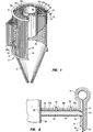
- FIG. 1 is a perspective/schematic view of a water-steam cooled cyclone separator which includes the roof of the present invention; and
- FIG. 2 is an enlarged cross-sectional view taken along a portion of the roof of the separator of FIG. 1, and showing the insulative material surrounding the roof.
- Referring to FIG. 1 of the drawings, the
reference numeral 10 refers in general to a cyclone separator which includes alower ring header 12 and anupper ring header 14. Thelower ring header 12 extends immediately above, and is connected to, aconical hopper 16 disposed at the lower portion of theseparator 10. - A group of vertically-extending, spaced,
parallel tubes 20 are connected at their lower ends to theheader 12 and extend vertically for the greater parts of their lengths to form a right circularouter cylinder 22. Thetubes 20 are connected by means of continuous fins (not shown) disposed at diametrically opposed portions of the tubes and connected thereto in a conventional manner to render the wall air-tight. A portion of thetubes 20 are bent out of the plane of theouter cylinder 22, as shown by thereference numeral 20a, to form aninlet passage 24 to the interior of the cylinder for reasons that will be described. - A plurality of
tiles 26 extend adjacent the inner wall of theouter cylinder 22 and are connected thereto in a conventional manner. A layer of refractory 28 (shown in Fig. 2) is placed between thetiles 26 and thetubes 20. The upper ends of thetubes 20 are connected to theupper header 14. - A plurality of
vertical pipes 29 extend upwardly from theupper header 14, it being understood that thelower header 12 can be connected to a source of cooling fluid, such as water, or steam, which passes from thelower header 12, through thetubes 20, and into theupper header 14 before being discharged, via thepipes 29, to external equipment. The direction of flow for the cooling fluid could also be reversed. - An inner cylinder, or barrel, 30 is disposed within the
outer cylinder 22, is formed from a solid, metallic material, such as stainless steel or high alloy austenitic, and has an upper end portion extending slightly above the plane formed by theupper header 14. The length of theinner cylinder 30 approximately coincides with the inlet passage formed by thebent tube portions 20a. Thus, an annular passage is formed between the outer surface of theinner cylinder 30 and the inner surface of theouter cylinder 22, for reasons that will be discussed. A roof 34 extends between upper portions of the outer andinner cylinders - The roof 34 comprises an annular
upper seal plate 36 having a plurality ofcorrugations 38 and having inner and outerU-fold expansion joints outer portions corrugations 38 extend radially from an axis of theupper seal plate 36 so that they can accommodate differential circumferential thermal expansion across the roof 34. The inner andouter expansion joints upper seal plate 36. Theexpansion joints inner expansion joint 40 is secured to the outer edge of theinner plate portion 36a, and the outer end of theinner expansion joint 40 is secured to the inner edge of themedial plate portion 36b. Similarly, the inner end of theouter expansion joint 42 is secured to the outer edge of themedial plate portion 36b, and the outer end of theouter expansion joint 42 is secured to the inner edge of theouter plate portion 36c. The inner and outer ends of theexpansion joints respective plate portions expansion joint - In one embodiment, the inner and
outer expansion joints upper plate 36 and together form inner and outer polygons aligned coaxially with the inner and outer circumferences of the upper seal plate. - It is understood that each expansion joint may be made in one piece or in any number of segments, and each expansion joint may be disposed in the upper seal plate in any number of positions. It is also understood that the expansion joints need not be in a "U" configuration but may be in a "W" or similar type configuration. It is further understood that fewer or more expansion joints may be utilized.
- Referring to FIG. 2, the inner circumference of the
upper seal plate 36 is affixed to aninner ring 46, such as by welding, and theinner ring 46 is affixed to the outer wall of theinner cylinder 30, such as by welding. It is understood that the inner circumference of theupper plate 36 may be affixed directly or by other means to the outer wall of the inner cylinder. An upper support, or bracket, 48 is affixed to the inner wall of theouter cylinder 22. The outer circumference of theupper seal plate 36 is affixed to theupper support ring 48, such as by welding, or directly to theouter cylinder 22. - An
annular shield plate 54 is disposed below theupper seal plate 36 and extends between the inner andouter cylinders shield plate 54 is affixed to the outer wall of theinner cylinder 30, such as by welding, or may rest on a support ring (not shown) that is affixed toinner cylinder 30. The outer circumference of theshield plate 54 rests upon, but is not welded or otherwise affixed to, a lower su pport orbracket 56 which is affixed to the inner wall of theouter cylinder 22. Theshield plate 54 is preferably made of Hastelloy metal but may be made of a high alloy austenitic or stainless steel material, depending upon the erosion characteristics of the fuel used in the system. -
Insulative material 60, such as an annular ceramic fiber blanket, is sandwiched between theupper seal plate 36 and theshield plate 54. Additional layers ofinsulation 64, such as mineral wool batt, may be added above theupper seal plate 36, along the outer wall of theouter cylinder 22, around the outer surfaces of thering headers - It is understood that an upper hood, or the like (not shown), can be provided above the plane formed by the
upper header 14 and can be connected to the inner cylinder 30 (not shown). The hood can be top supported from the roof of the structure in which theseparator 10 is placed, and the remaining portion of the separator can be supported from hangers connected to theupper header 14 orpipes 29. - In operation, and assuming the roof of the present invention and the
separator 10 are part of a boiler system including a fluidized bed reactor, or the like, disposed adjacent the separator, theinlet passage 24 formed by thebent tube portions 20a receives hot gases from the reactor, which gases contain entrained fine solid particulate fuel material from the fluidized bed. The gases containing the particulate material thus enter and swirl around in the annular chamber defined between theouter cylinder 22 and theinner cylinder 30, and the entrained solid particles are propelled against the inner wall of theouter cylinder 22 where they collect and fall downwardly by gravity into thehopper 16. The relatively clean gases remaining in the annular chamber are prevented from flowing upwardly by theshield plate 54 and theupper seal plate 36, and thus enter theinner cylinder 30 through its lower end. The gases thus pass through the length of theinner cylinder 30 before exiting from the upper end of the inner cylinder to the aforementioned hood, or the like, for directing the hot gases to external equipment for further use. - Water or steam from an external source passes into the
lower header 12 and passes upwardly through thetubes 20 before exiting, via theupper header 14 and thepipes 29, to external circuitry which may form a portion of the boiler system including theseparator 10. The water thus maintains the wall of theouter cylinder 22 at a relatively low temperature. Accordingly, thecyclone separator 10 will typically be operated such that theinner cylinder 30 is at a relatively high temperature, such as 1600°F, and theouter cylinder 22 is at a relatively low temperature, such as 700°F. - It can thus be appreciated that there will be differential circumferential and radial thermal expansion and contraction across the roof 34 which extends between the relatively high temperature inner cylinder and the relatively low temperature outer cylinder. The expansion joints 40, 42 accommodate relative radial movement of the roof 34 between the inner and
outer cylinders corrugations 38 of theupper seal plate 36 accommodate relative circumferential movement across the roof 34. The outer circumference of theshield plate 54 rests on thelower support 56, and the inner circumference of theshield plate 54 may be affixed directly to theinner cylinder 30 or supported on a ring (not shown) that is affixed, such as by welding, to theinner cylinder 30 so that theshield plate 54 is able to move and absorb the radial and axial movements due to differential expansion. - Several advantages result from the foregoing arrangement. For example, the bulk, weight, and cost of the separator roof of the present invention are much less than those of conventional separator roofs. The separator roof of the present invention also permits one to utilize the advantages of water-steam cooled cyclone separators while eliminating the need for expensive, difficult-to-construct roofs formed by water-steam cooled tubes. The separator roof of the present invention will also accommodate differential circumferential and radial thermal expansion and contraction. The separator roof of the present invention further provides an independent roof for a cyclone separator which reduces the overall costs, decreases the fabrication cycle, and provides greater flexibility from an erection standpoint.
- Other modifications, changes, and substitutions are intended in the foregoing disclosure and in some instances some features of the invention will be employed without a corresponding use of other features. Accordingly, it is appropriate that the appended claims be construed broadly and in a manner consistent with the spirit and scope of the invention herein.
Claims (21)
wherein said first means comprises an inner expansion joint and an outer expansion joint, said inner and outer expansion joints being secured to said upper plate and being aligned coaxially with said inner circumference of said upper plate.
wherein said expansion joint is aligned coaxially with said inner circumference of said upper plate.
Applications Claiming Priority (2)
| Application Number | Priority Date | Filing Date | Title |
|---|---|---|---|
| US07/673,920 US5116394A (en) | 1991-03-25 | 1991-03-25 | Cyclone separator roof |
| US673920 | 1991-03-25 |
Publications (2)
| Publication Number | Publication Date |
|---|---|
| EP0506343A2 true EP0506343A2 (en) | 1992-09-30 |
| EP0506343A3 EP0506343A3 (en) | 1993-06-02 |
Family
ID=24704633
Family Applications (1)
| Application Number | Title | Priority Date | Filing Date |
|---|---|---|---|
| EP19920302536 Withdrawn EP0506343A3 (en) | 1991-03-25 | 1992-03-25 | Cyclone separator roof |
Country Status (5)
| Country | Link |
|---|---|
| US (1) | US5116394A (en) |
| EP (1) | EP0506343A3 (en) |
| JP (1) | JPH0738956B2 (en) |
| CA (1) | CA2061887A1 (en) |
| MX (1) | MX9201145A (en) |
Families Citing this family (20)
| Publication number | Priority date | Publication date | Assignee | Title |
|---|---|---|---|---|
| CA2089424A1 (en) * | 1992-03-02 | 1993-09-03 | Michael Garkawe | Expansion seal assembly |
| US5417932A (en) * | 1993-06-21 | 1995-05-23 | Texaco Inc. | Vent orifice in fluid catalytic cracking direct-connected cyclone apparatus |
| FI107435B (en) | 1996-11-19 | 2001-08-15 | Foster Wheeler Energia Oy | Centrifugal separator device and process for separating particles from hot gas of a fluidized bed reactor |
| FI114289B (en) * | 2000-04-07 | 2004-09-30 | Foster Wheeler Energia Oy | Device for separating particles from hot gases |
| EE05544B1 (en) * | 2007-09-05 | 2012-06-15 | Aktsiaselts Narva ?Litehas | Dust extraction chamber for separating solid particles from a vapor-gas mixture |
| MX2011000506A (en) * | 2008-07-15 | 2011-04-05 | Mi Llc | Oil vapor cleaner. |
| US9068743B2 (en) * | 2009-02-26 | 2015-06-30 | 8 Rivers Capital, LLC & Palmer Labs, LLC | Apparatus for combusting a fuel at high pressure and high temperature, and associated system |
| US8986002B2 (en) | 2009-02-26 | 2015-03-24 | 8 Rivers Capital, Llc | Apparatus for combusting a fuel at high pressure and high temperature, and associated system |
| MX345743B (en) | 2009-02-26 | 2017-02-14 | 8 Rivers Capital Llc | Apparatus and method for combusting a fuel at high pressure and high temperature, and associated system and device. |
| US8157895B2 (en) * | 2010-05-04 | 2012-04-17 | Kellogg Brown & Root Llc | System for reducing head space in a pressure cyclone |
| US8869889B2 (en) | 2010-09-21 | 2014-10-28 | Palmer Labs, Llc | Method of using carbon dioxide in recovery of formation deposits |
| AU2014305660B2 (en) | 2013-08-09 | 2018-02-22 | Weir Minerals Australia Ltd | Cyclone separator apparatus and methods of production |
| CN103471092B (en) * | 2013-09-05 | 2015-07-15 | 无锡华光锅炉股份有限公司 | Supporting structure used for preventing circulating fluidized bed boiler center cylinder from falling off |
| FI126040B (en) * | 2014-07-09 | 2016-06-15 | Amec Foster Wheeler En Oy | Particle separator and fluidized bed reactor that can be connected to a fluidized bed reactor |
| EP2995788B1 (en) * | 2014-09-12 | 2019-06-26 | Rolls-Royce Corporation | Fuel cooled cyclonic air oil separator |
| BR112019018476A2 (en) | 2017-03-07 | 2020-04-14 | 8 Rivers Capital Llc | system and method for the combustion of solid fuels and derivatives thereof |
| WO2018162994A1 (en) | 2017-03-07 | 2018-09-13 | 8 Rivers Capital, Llc | System and method for operation of a flexible fuel combustor for a gas turbine |
| WO2020021456A1 (en) | 2018-07-23 | 2020-01-30 | 8 Rivers Capital, Llc | System and method for power generation with flameless combustion |
| CN112390261A (en) * | 2019-08-13 | 2021-02-23 | 斯特里特技术有限公司 | System and method for separation and dehydrogenation of fumed silica particles |
| CN111718743A (en) * | 2020-06-22 | 2020-09-29 | 洛阳瑞昌环境工程有限公司 | Thermal expansion self-absorption large-hole distribution plate |
Citations (6)
| Publication number | Priority date | Publication date | Assignee | Title |
|---|---|---|---|---|
| US3470678A (en) * | 1967-06-20 | 1969-10-07 | Exxon Research Engineering Co | Cyclone separator for high temperature operations |
| FR2129758A5 (en) * | 1971-03-17 | 1972-10-27 | Sinoski Donald | |
| GB2016328A (en) * | 1978-03-20 | 1979-09-26 | Schmidt Gmbh Karl | Cover for vessels for holding molten metal |
| US4479817A (en) * | 1980-04-03 | 1984-10-30 | Dorr-Oliver, Inc. | Pressurized hot cyclone |
| US4712938A (en) * | 1986-01-13 | 1987-12-15 | Foster Wheeler Energy Corporation | Expansion seal assembly |
| EP0298671A2 (en) * | 1987-07-06 | 1989-01-11 | Foster Wheeler Energy Corporation | Cyclone separator having water-steam cooled walls |
Family Cites Families (7)
| Publication number | Priority date | Publication date | Assignee | Title |
|---|---|---|---|---|
| US1032012A (en) * | 1911-04-10 | 1912-07-09 | Charles E Martin | Roof for silos or the like. |
| US1907268A (en) * | 1931-08-03 | 1933-05-02 | Parkersburg Rig And Reel Compa | Tank deck |
| JPS6014959B2 (en) * | 1978-12-07 | 1985-04-16 | 三菱重工業株式会社 | Distortion-free low temperature tank |
| FR2527478A1 (en) * | 1982-05-26 | 1983-12-02 | Creusot Loire | Cyclone separator - comprising gas-tight vertical cylindrical chamber into which gas enters tangentially at top |
| US4615715A (en) * | 1985-03-15 | 1986-10-07 | Foster Wheeler Energy Corporation | Water-cooled cyclone separator |
| US4746337A (en) * | 1987-07-06 | 1988-05-24 | Foster Wheeler Energy Corporation | Cyclone separator having water-steam cooled walls |
| US4944250A (en) * | 1989-03-30 | 1990-07-31 | Foster Wheeler Energy Corporation | Cyclone separator including a hopper formed by water-steam cooled walls |
-
1991
- 1991-03-25 US US07/673,920 patent/US5116394A/en not_active Expired - Fee Related
-
1992
- 1992-02-26 CA CA002061887A patent/CA2061887A1/en not_active Abandoned
- 1992-03-03 JP JP4045378A patent/JPH0738956B2/en not_active Expired - Lifetime
- 1992-03-16 MX MX9201145A patent/MX9201145A/en not_active IP Right Cessation
- 1992-03-25 EP EP19920302536 patent/EP0506343A3/en not_active Withdrawn
Patent Citations (6)
| Publication number | Priority date | Publication date | Assignee | Title |
|---|---|---|---|---|
| US3470678A (en) * | 1967-06-20 | 1969-10-07 | Exxon Research Engineering Co | Cyclone separator for high temperature operations |
| FR2129758A5 (en) * | 1971-03-17 | 1972-10-27 | Sinoski Donald | |
| GB2016328A (en) * | 1978-03-20 | 1979-09-26 | Schmidt Gmbh Karl | Cover for vessels for holding molten metal |
| US4479817A (en) * | 1980-04-03 | 1984-10-30 | Dorr-Oliver, Inc. | Pressurized hot cyclone |
| US4712938A (en) * | 1986-01-13 | 1987-12-15 | Foster Wheeler Energy Corporation | Expansion seal assembly |
| EP0298671A2 (en) * | 1987-07-06 | 1989-01-11 | Foster Wheeler Energy Corporation | Cyclone separator having water-steam cooled walls |
Also Published As
| Publication number | Publication date |
|---|---|
| US5116394A (en) | 1992-05-26 |
| JPH0738956B2 (en) | 1995-05-01 |
| CA2061887A1 (en) | 1992-09-26 |
| MX9201145A (en) | 1992-10-01 |
| JPH04367752A (en) | 1992-12-21 |
| EP0506343A3 (en) | 1993-06-02 |
Similar Documents
| Publication | Publication Date | Title |
|---|---|---|
| US5116394A (en) | Cyclone separator roof | |
| US4904286A (en) | Cyclone separator having water-steam cooled walls | |
| US4615715A (en) | Water-cooled cyclone separator | |
| EP0413599B1 (en) | Cyclone separator wall refractory material system | |
| US4944250A (en) | Cyclone separator including a hopper formed by water-steam cooled walls | |
| US5117770A (en) | Combustion unit | |
| CA1314497C (en) | Low stress cyclone gas collection systems | |
| EP0298671A2 (en) | Cyclone separator having water-steam cooled walls | |
| JPH0774681B2 (en) | Fluidized bed combustor utilizing improved connection between reactor and separator | |
| US5383316A (en) | Loop seal expansion joint | |
| US5443654A (en) | Method of removing deposits from the walls of a gas cooler inlet duct, and a gas cooler inlet duct having a cooled elastic metal structure | |
| US5269262A (en) | Combustion unit | |
| JP2788117B2 (en) | Power plant with a combustor that burns in a fluidized bed | |
| CA1323585C (en) | Cyclone separator having water-steam cooled walls | |
| EP0543564B1 (en) | Water-cooled cyclone separator | |
| CA1327946C (en) | Cyclone separator having water-steam cooled walls | |
| CN2398508Y (en) | Water cooled cyclone separator | |
| JP2729530B2 (en) | Fluidized bed steam generator including steam cooled cyclone separator | |
| JP6653186B2 (en) | Refractory structures | |
| SK3832000A3 (en) | Cyclone refractory system | |
| JP3185379B2 (en) | Pressurized fluidized bed boiler | |
| GB2050585A (en) | Gas generator for fine-grained carbonaceous fuels | |
| JP3348894B2 (en) | Connection structure between transfer duct and furnace wall in gas cooler | |
| JPH0435755A (en) | Cyclone separator | |
| JPH06147456A (en) | Discharged gas manihold for boiler |
Legal Events
| Date | Code | Title | Description |
|---|---|---|---|
| PUAI | Public reference made under article 153(3) epc to a published international application that has entered the european phase |
Free format text: ORIGINAL CODE: 0009012 |
|
| AK | Designated contracting states |
Kind code of ref document: A2 Designated state(s): ES GB IT PT |
|
| PUAL | Search report despatched |
Free format text: ORIGINAL CODE: 0009013 |
|
| AK | Designated contracting states |
Kind code of ref document: A3 Designated state(s): ES GB IT PT |
|
| PUAF | Information related to the publication of a search report (a3 document) modified or deleted |
Free format text: ORIGINAL CODE: 0009199SEPU |
|
| PUAL | Search report despatched |
Free format text: ORIGINAL CODE: 0009013 |
|
| D17D | Deferred search report published (deleted) | ||
| AK | Designated contracting states |
Kind code of ref document: A3 Designated state(s): ES GB IT PT |
|
| 17P | Request for examination filed |
Effective date: 19931119 |
|
| 17Q | First examination report despatched |
Effective date: 19950207 |
|
| GRAG | Despatch of communication of intention to grant |
Free format text: ORIGINAL CODE: EPIDOS AGRA |
|
| STAA | Information on the status of an ep patent application or granted ep patent |
Free format text: STATUS: THE APPLICATION IS DEEMED TO BE WITHDRAWN |
|
| 18D | Application deemed to be withdrawn |
Effective date: 19971001 |