EP0506203B1 - Drapery suspension system - Google Patents
Drapery suspension system Download PDFInfo
- Publication number
- EP0506203B1 EP0506203B1 EP19920200883 EP92200883A EP0506203B1 EP 0506203 B1 EP0506203 B1 EP 0506203B1 EP 19920200883 EP19920200883 EP 19920200883 EP 92200883 A EP92200883 A EP 92200883A EP 0506203 B1 EP0506203 B1 EP 0506203B1
- Authority
- EP
- European Patent Office
- Prior art keywords
- rail section
- roller
- section
- suspension system
- travelling
- Prior art date
- Legal status (The legal status is an assumption and is not a legal conclusion. Google has not performed a legal analysis and makes no representation as to the accuracy of the status listed.)
- Expired - Lifetime
Links
- 239000000725 suspension Substances 0.000 title claims description 20
- 230000000994 depressogenic effect Effects 0.000 claims description 3
- 229920003023 plastic Polymers 0.000 claims description 3
- 239000004033 plastic Substances 0.000 claims description 3
- 230000002950 deficient Effects 0.000 description 3
- 238000010276 construction Methods 0.000 description 1
- 239000000463 material Substances 0.000 description 1
- 238000005096 rolling process Methods 0.000 description 1
Images
Classifications
-
- A—HUMAN NECESSITIES
- A47—FURNITURE; DOMESTIC ARTICLES OR APPLIANCES; COFFEE MILLS; SPICE MILLS; SUCTION CLEANERS IN GENERAL
- A47H—FURNISHINGS FOR WINDOWS OR DOORS
- A47H15/00—Runners or gliders for supporting curtains on rails or rods
- A47H15/02—Runners
Definitions
- This invention relates to a drapery suspension system, substantially consisting of a rail section of C-shaped cross-section and a series of roller elements slidably mounted in the rail section.
- the rail section If it is desired for the rail section to be mounted in such a manner that no space is left between the ends of the rail section and the adjacent sidewalls, it is necessary to insert as many roller elements into the rail section as there are folds in the drapery before mounting the rail section on the ceiling or a wall.
- the drapery suspension system When at a later time the drapery is to be replaced by another material with a corresponding, different number of folds, the drapery suspension system must be demounted to enable the newly required number of roller elements to be inserted into the rail section.
- each roller element comprises a travelling roller which is capable of running over the bottom of the rail section and is mounted in a chassis of plastics, in which on the side remote from the bearing surface of the travelling roller a hole is provided so as to form a resiliently depressible arcuate wall whereby the roller element (11) is made resilient in a direction perpendicular to the longitudinal axis of the rail section (1) and parallel to the principal plane thereof, enabling said roller element to be clicked into or removed from said rail section at any point thereof.
- Mounting the travelling roller in a chassis moreover offers the advantage that the travelling rollers cannot jam in the rail section when the draperies attached thereto are being opened.
- the amount of spring travel of the travelling roller chassis is selected such that when the arcuate wall has been depressed, the travelling roller can be removed from or clicked into the rail by means of a pivoting motion.
- DE-C-581,364 discloses a drapery suspension system consisting of a rail section and roller elements which can be moved along this section, which roller elements can be fitted on and removed from the rail section at any point thereof.
- the rail section is I-shaped in cross-section and each roller element comprises two travelling rollers which are mounted at the end of two legs which are coupled for mutual hinging motion by means of a resilient hinge.
- the legs of each roller element can be opened in the manner of a clothes-peg or scissors so as to shift the roller elements from below over the lower flange of the I-shaped section.
- the two travelling rollers run on opposite sides of the principal plane of the section over the lower flange thereof extending in transverse direction.
- roller elements in mounted position are not hidden from view, there is the technical drawback that the roller elements each consist of two travelling rollers and legs that can be hinged relative to each other.
- U.S.-A-2,848,735 discloses a drapery suspension system in which the carrier elements slidably mounted in the C-shaped rail section are provided with resilient legs which provide the possibility of mounting or dismounting a carrier element at any point of the rail section.
- the carrier elements as in the system according to U.S.-A-3,293,685, discussed above, are mounted between the edges of the C-shaped rail section that have been so bent as to be directed to each other, but do not comprise travelling rollers that can be moved substantially without resistance. On the contrary, the carrier elements move in sliding or shifting fashion over the bent edge of the rail section.
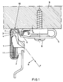
- the drapery suspension system according to Fig. 1 comprises a rail section 1 of C-shaped cross-section, closed on three sides and comprising a lower edge 2 and an upper edge 3 which have been bent and directed towards each other.
- the upper edge 3 comprises an attaching section 4 formed thereon, which can be mounted between the legs 6 and 7 of a retaining clamp 5 via which the rail section 1 can be screwed to a ceiling 9 by means of screws 8.
- the number of clamps to be used naturally depends on the weight of the drapery to be suspended.
- the highest point of the attaching section 4 is disposed lower than the top surface 10 of the rail section 11 by a distance h, so that this top surface 10 in mounted position can abut the ceiling 9 so as to obviate the aesthetically undesirable gap between the ceiling 9 and the top surface 10 of the rail section 1.
- roller elements 11 Arranged within the rail section 1 are a plurality of roller elements 11 which can be moved in a direction perpendicular to the plane of the paper.
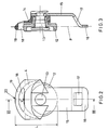
- the construction of this roller element 11 is shown to an enlarged scale in Figs 2 and 3.
- the roller element 11 comprises a travelling roller proper 12 which is bearing-mounted on a rivet pin 13 within a chassis 14 made of plastics.
- a vertically depending carrying member 15 is mounted on the chassis 14.
- the end of the carrying member 15 is bent in such a manner that this end 16 is located in the principal plane P of the travelling roller 12.
- an opening 17 is provided in the carrying member 15 adjacent the end 16 for receiving the drapery hooks.
- the travelling roller chassis 14 is provided at the top thereof with a sickle-shaped hole 18 so as to form a resiliently depressible arcuate wall 19 which is bounded by the circumferential surface 20.
- the distance L between the circumferential surface 20 and the travelling surface of roller 12 is only slightly smaller than the internal distance between the top and bottom surfaces 10 of the C-shaped rail section 1, so that the roller element 11 remains locked within the rail section 1, and the surface 20 remains clear of the top surface of the rail section 1 during the rolling motion of the roller elements 11.
- Inserting the roller elements 11 into the rail section 1 takes place in the manner as shown schematically in Fig. 1.
- the roller element is inserted obliquely into the rail section 1 according to the direction F until the circumferential surface 20 abuts against the transitional arc between the horizontal and vertical plane of the rail section 1. Then some pressure is brought to bear on the roller element 11 in the direction F, so that the resiliently depressible arcuate wall 19 can be depressed over the spring travel distance v until the wall 19 abuts the bottom surface of the sickle-shaped hole 18.
- the roller element 11 can be pivoted in the direction R, whereby the bottom surface of the travelling roller 12 can pass the upright lower edge 2 of the rail section 1, whereafter the roller element 11 is locked in the rail section in the position shown in Fig. 1. Removal of the roller element is effected in exactly the same manner. The roller element 11 is pushed up and then pivoted in the opposite direction, whereafter the roller element 11 can be removed from the rail section 1 according to the direction F.
- the roller elements 11 remain in the desired, vertical position owing to the fact that the point of suspension, i.e., the end 16, is located in the principal plane P of the travelling roller 12 of the roller element 11.
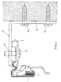
- Fig. 4 shows the drapery suspension system according to Fig. 1, but now it is mounted on a wall 25.
- the retaining clamps 5 are affixed to the horizontal leg of an L-shaped bracket 21, which is screwed to the wall 25 by means of two screws 22.
- the clamp 5 is fixed to the horizontal leg 21 provided with a threaded hole 24 for receiving the bolt 23.
Landscapes
- Curtains And Furnishings For Windows Or Doors (AREA)
- Supports Or Holders For Household Use (AREA)
- Support Devices For Sliding Doors (AREA)
Applications Claiming Priority (2)
| Application Number | Priority Date | Filing Date | Title |
|---|---|---|---|
| NL9100553A NL9100553A (nl) | 1991-03-28 | 1991-03-28 | Gordijn-ophangsysteem. |
| NL9100553 | 1991-03-28 |
Publications (2)
| Publication Number | Publication Date |
|---|---|
| EP0506203A1 EP0506203A1 (en) | 1992-09-30 |
| EP0506203B1 true EP0506203B1 (en) | 1996-02-21 |
Family
ID=19859072
Family Applications (1)
| Application Number | Title | Priority Date | Filing Date |
|---|---|---|---|
| EP19920200883 Expired - Lifetime EP0506203B1 (en) | 1991-03-28 | 1992-03-27 | Drapery suspension system |
Country Status (5)
| Country | Link |
|---|---|
| EP (1) | EP0506203B1 (pl) |
| DE (1) | DE69208380T2 (pl) |
| ES (1) | ES2084918T3 (pl) |
| NL (1) | NL9100553A (pl) |
| PL (1) | PL169276B1 (pl) |
Families Citing this family (1)
| Publication number | Priority date | Publication date | Assignee | Title |
|---|---|---|---|---|
| FR2800794B1 (fr) | 1999-11-05 | 2003-07-04 | Rehau Sa | Caisson de volet roulant avec profile de suspension integre pour rideau ou autre piece ou structure d'occultation interieure |
Family Cites Families (7)
| Publication number | Priority date | Publication date | Assignee | Title |
|---|---|---|---|---|
| DE581364C (de) * | 1933-07-26 | Valer Flax | Laufrollenaufhaenger fuer Vorhaenge, Gardinen o. dgl. | |
| US1658271A (en) * | 1926-01-26 | 1928-02-07 | Wilson Ernest Lodge | Curtain-suspension device |
| US2683890A (en) * | 1953-04-10 | 1954-07-20 | Eastern Venetian Blind Company | Drapery traverse rod assembly |
| US2848735A (en) * | 1955-03-07 | 1958-08-26 | Ault | Drapery carrier |
| US3199142A (en) * | 1963-09-19 | 1965-08-10 | Graber Mfg Company Inc | Drapery slide |
| US3293685A (en) * | 1964-11-17 | 1966-12-27 | Eastern Prod Corp | Drapery carrier |
| ZA828653B (pl) * | 1981-12-04 | 1983-08-08 |
-
1991
- 1991-03-28 NL NL9100553A patent/NL9100553A/nl not_active Application Discontinuation
-
1992
- 1992-03-27 EP EP19920200883 patent/EP0506203B1/en not_active Expired - Lifetime
- 1992-03-27 ES ES92200883T patent/ES2084918T3/es not_active Expired - Lifetime
- 1992-03-27 PL PL29399792A patent/PL169276B1/pl unknown
- 1992-03-27 DE DE1992608380 patent/DE69208380T2/de not_active Expired - Fee Related
Also Published As
| Publication number | Publication date |
|---|---|
| DE69208380T2 (de) | 1996-07-18 |
| PL293997A1 (en) | 1992-11-02 |
| PL169276B1 (pl) | 1996-06-28 |
| EP0506203A1 (en) | 1992-09-30 |
| DE69208380D1 (de) | 1996-03-28 |
| ES2084918T3 (es) | 1996-05-16 |
| NL9100553A (nl) | 1992-10-16 |
Similar Documents
| Publication | Publication Date | Title |
|---|---|---|
| EP0801257B1 (en) | Universal beam hanger | |
| US2754535A (en) | Frameless plate glass door hanger | |
| CA1334084C (en) | Modular shelving and hanger bar system | |
| CA2140212A1 (en) | A pull-out mechanism for drawers | |
| US4359080A (en) | Hanger for folding partition | |
| US4633614A (en) | Adjustable tub enclosure and shower stall doors | |
| US4112622A (en) | Roller assembly for sliding screen door, and the like | |
| US20030052244A1 (en) | Curtain rods and supports therefor | |
| US2533778A (en) | Sign display frame | |
| KR840007814A (ko) | 드레이퍼리 지지 및 횡단 시스템 | |
| EP0506203B1 (en) | Drapery suspension system | |
| EP2937502B1 (en) | Door stopper for a sliding door assembly | |
| US4391019A (en) | Corner connector for sliding doors | |
| US5209357A (en) | Hanging book end device | |
| US4380260A (en) | Folding closure with a sweeper | |
| EP0855477A3 (de) | Deckenaufbau | |
| US4034439A (en) | Traverse rod for decorations, in particular for curtains | |
| AU739513B2 (en) | Adjustable two-piece clip for mounting objects on a wall stud | |
| US3550291A (en) | Adjustable chalkboard assembly | |
| US5494175A (en) | Hanging file support structure for a drawer | |
| US2784444A (en) | Trackway and hanger for a sliding door | |
| US5395169A (en) | Pull-out guide for drawers | |
| US1758292A (en) | Support for maps and analogous devices | |
| US4887873A (en) | File system with hang rail | |
| DE19833962B4 (de) | Kühlschranktür |
Legal Events
| Date | Code | Title | Description |
|---|---|---|---|
| PUAI | Public reference made under article 153(3) epc to a published international application that has entered the european phase |
Free format text: ORIGINAL CODE: 0009012 |
|
| AK | Designated contracting states |
Kind code of ref document: A1 Designated state(s): BE DE ES FR LU NL PT |
|
| 17P | Request for examination filed |
Effective date: 19930330 |
|
| 17Q | First examination report despatched |
Effective date: 19940421 |
|
| GRAH | Despatch of communication of intention to grant a patent |
Free format text: ORIGINAL CODE: EPIDOS IGRA |
|
| GRAA | (expected) grant |
Free format text: ORIGINAL CODE: 0009210 |
|
| AK | Designated contracting states |
Kind code of ref document: B1 Designated state(s): BE DE ES FR LU NL PT |
|
| REF | Corresponds to: |
Ref document number: 69208380 Country of ref document: DE Date of ref document: 19960328 |
|
| REG | Reference to a national code |
Ref country code: ES Ref legal event code: FG2A Ref document number: 2084918 Country of ref document: ES Kind code of ref document: T3 |
|
| ET | Fr: translation filed | ||
| SC4A | Pt: translation is available |
Free format text: 960305 AVAILABILITY OF NATIONAL TRANSLATION |
|
| PLBE | No opposition filed within time limit |
Free format text: ORIGINAL CODE: 0009261 |
|
| STAA | Information on the status of an ep patent application or granted ep patent |
Free format text: STATUS: NO OPPOSITION FILED WITHIN TIME LIMIT |
|
| 26N | No opposition filed | ||
| PGFP | Annual fee paid to national office [announced via postgrant information from national office to epo] |
Ref country code: DE Payment date: 20001124 Year of fee payment: 10 |
|
| PGFP | Annual fee paid to national office [announced via postgrant information from national office to epo] |
Ref country code: PT Payment date: 20001130 Year of fee payment: 10 Ref country code: FR Payment date: 20001130 Year of fee payment: 10 |
|
| PGFP | Annual fee paid to national office [announced via postgrant information from national office to epo] |
Ref country code: BE Payment date: 20001215 Year of fee payment: 10 |
|
| PGFP | Annual fee paid to national office [announced via postgrant information from national office to epo] |
Ref country code: LU Payment date: 20010322 Year of fee payment: 10 |
|
| PGFP | Annual fee paid to national office [announced via postgrant information from national office to epo] |
Ref country code: NL Payment date: 20010331 Year of fee payment: 10 |
|
| PGFP | Annual fee paid to national office [announced via postgrant information from national office to epo] |
Ref country code: ES Payment date: 20010409 Year of fee payment: 10 |
|
| PG25 | Lapsed in a contracting state [announced via postgrant information from national office to epo] |
Ref country code: LU Free format text: LAPSE BECAUSE OF NON-PAYMENT OF DUE FEES Effective date: 20020327 |
|
| PG25 | Lapsed in a contracting state [announced via postgrant information from national office to epo] |
Ref country code: ES Free format text: LAPSE BECAUSE OF NON-PAYMENT OF DUE FEES Effective date: 20020328 |
|
| PG25 | Lapsed in a contracting state [announced via postgrant information from national office to epo] |
Ref country code: BE Free format text: LAPSE BECAUSE OF NON-PAYMENT OF DUE FEES Effective date: 20020331 |
|
| BERE | Be: lapsed |
Owner name: THOMAS *REGOUT N.V. Effective date: 20020331 |
|
| PG25 | Lapsed in a contracting state [announced via postgrant information from national office to epo] |
Ref country code: PT Free format text: LAPSE BECAUSE OF NON-PAYMENT OF DUE FEES Effective date: 20020930 |
|
| PG25 | Lapsed in a contracting state [announced via postgrant information from national office to epo] |
Ref country code: NL Free format text: LAPSE BECAUSE OF NON-PAYMENT OF DUE FEES Effective date: 20021001 Ref country code: DE Free format text: LAPSE BECAUSE OF NON-PAYMENT OF DUE FEES Effective date: 20021001 |
|
| PG25 | Lapsed in a contracting state [announced via postgrant information from national office to epo] |
Ref country code: FR Free format text: LAPSE BECAUSE OF NON-PAYMENT OF DUE FEES Effective date: 20021129 |
|
| NLV4 | Nl: lapsed or anulled due to non-payment of the annual fee |
Effective date: 20021001 |
|
| REG | Reference to a national code |
Ref country code: PT Ref legal event code: MM4A Free format text: LAPSE DUE TO NON-PAYMENT OF FEES Effective date: 20020930 |
|
| REG | Reference to a national code |
Ref country code: FR Ref legal event code: ST |
|
| REG | Reference to a national code |
Ref country code: ES Ref legal event code: FD2A Effective date: 20030410 |