-
The present invention concerns a switching power supply device also known as a variable control "chopper", and more precisely having time durations of the conduction and blocking conditions (usually called time-on and time-off, respectively) that are variable. More particularly, the device of the invention is advantageously employed in apparatuses for carrying out nondestructive tests, such as industrial radiography or X-ray photographs in the field, for testing and checking industrial products such as manufactured articles, welds, etc.
-
These radiographies are usually accomplished by using X-rays, i.e. electromagnetic radiations with a wavelength from 5 to 0.1 Angstroms, or gamma radiations having a shorter wavelength. More particularly the invention concerns the accomplishment of radiographies or photographs by means of X-rays.
-
Industrial X-ray photographs are usually carried out by means of generally movable apparatuses comprising a radiation source made up by a vacuum tube adapted to emit X-rays through the collision of accelerated electrons against one target electrode, and a power supplying device for feeding such tube through the power drawn by a local source or a battery.
-
The radiation source is activated to radiate the article to be tested behind which or within which a suitable sensible film or plate is located, in case sandwiched between shielding thin metal foils to improve the image definition.
-
The generating tube, also known as X-ray tube, comprises two electrodes, a cathode and an anode, housed within a bulb between which a very high voltage is applied, in the order of 100-300 kV and higher. The cathode emits electrons thanks to the heating of a tungsten filament rendered incandescent by a circulating current of a few Amperes, whereas a tungsten plate (also known as anticathode) is welded to the anode that emits X-rays when hit by the electrons being accelerated by the potential difference between anode and cathode.
-
The power supply device comprises a high voltage transformer adapted to supply the required anode-cathode voltages from a locally available power source. As a function of the characteristics of the article to be X-ray photographed, the tube is fed with a high voltage of a proper value, set each time, and anyhow not higher than the maximum value specified by the tube manufacturer.
-
The power of the generated X-rays, and hence the depth of their penetration, depends upon the voltage applied between cathode and anode, hereinafter also simply called high voltage, whereas the intensity of the emitted X-ray beam is a function of the feeding characteristics of the filament which is fed by a voltage of a few Volts (low voltage). The filament temperature is adjusted by acting on a so-called mA knob.
-
There are known transportable industrial X-ray apparatuses in which in order to decrease the weight of the high voltage transformer there is employed a DC pulse power supply working at a frequency quite higher than that of the mains (50 or 60 Hz), typically in the order of some hundreds of Hz. This way it has become possible to reduce by approximately one half the weight of the high voltage transformer, and hence the weight of the whole apparatus.
-
These known apparatuses furthe comprise, besides the high voltage transformer, a circuit for regulating the DC voltage supplied by the local source, and a switching device or chopper which is not provided with a feedback loop since it is rather troublesome to sense the real value of so high voltages and operate quickly enough. More particularly, when it is desided to adjust at will the output voltage of the high voltage transformer in view of the type of the X-ray photographs to be taken, it has to be taken into account the non-linear relationship between the high voltage values and the low voltage valuse caused by the transformer nucleus, as well as the difficulties of using effective high voltage sensors.
-
Although these known power supply devices for controlling the high voltage have appreciably reduced the transformer weight, nevertheless they are still not completely satisfactory due to several reasons.
-
Namely the control of the correspondence between the high voltage set on the control panel and that really applied to the tube is still rather critical since due to the strong currents produced by the use of a chopping circuit, even small changes in the total impedance of the circuit cause relevant changes of the high voltage, with the risk of triggering a disruptive discharge in the X-ray tube. As a matter of fact, X-ray tubes have a very limited tolerance with respect to overvoltages and are permanentely damaged even by values exceeding by 10-20% the maximum rated voltage. Because of the difficulty of controlling the voltage peak induced on the secondary winding this latter often receives a voltage higher than the maximum admissible voltage and the damaging of the tube is not infrequent. This can take place particularly in apparatuses using the mains voltage as a power supply source, in case of overvoltage or surges in this latter.
-
Other shortcomings are encountered whenever the voltage is not regulated to maintain constant the set value, producing photographs of poor quality that must be repeated. Besides the plate cost there are to be accounted for the setup times and the safety procedure for each photograph which all add to the final operating cost of the apparatus.
-
Several and poorly predictable factors effect the final value of the secondary (high) voltage, such as mains oscillations, the length of the cables connecting the radiation source (tube and high voltage transformer) to the low voltage and control section of the apparatus, the components' efficiency (particularly the high voltage transformer) with the temperature and hence with the time from the turn on, the contact resistance of the connectors, the applied load, etc.
-
A further inconvenience of the known apparatuses resides in that the feeding for the X-ray tube's filament is drawn from the same secondary high voltage winding through an intermediate tap involving a few turns. This way, when setting a new value of the voltage to be applied to the X-ray tube, the voltage applied to the filament also changes and hence the current circulating therethrough (in the order of the Amperes), thus resulting in a change of the cathode temperature, and therefore of the emitted beam's intensity that can no longer match the selected exposition time.
-
The object of the present invention is that of realizing a power supply device of the above mentioned type, working at a frequency higher than that of the mains, that overcomes these shortcomings, and more particularly that maintains rigorously constant the (high) output voltage, and completely insensitive to variations of the voltage at the input of the secondary winding of the transformer due to different causes.
-
Moreover the device of the invention provides for continuously variable voltages from a very low value up to a maximum value in a simple and cheaper way, and further allows for the regulating of the current circulating through the X-ray tube.
-
The objects are accomplished by means of the invention consisting in an apparatus for performing industrial X-rays photographs comprising a DC voltage source connected to the primary winding of a high voltage transformer through a switch periodically opened and closed by control means, and an X-ray tube fed through the secondary winding of said high voltage transformer, characterized in that said high voltage transformer comprises an additional sensing winding, and in that said control means comprises a comparator having one input connected to the output of said sensing winding and the other input connected to a first reference voltage adjustable for setting a desired value of the high voltage applied to the X-ray tube, and a differential amplifier having one input connected to the return of the mA and the other input connected to a second reference voltage adjustable for setting a desired value of the current through the filament of the tube, the output of said comparator being connected to the reset input of a multivibrator the output of which controls the opening and the closing of said switch, the output of the differential amplifier being connected through a voltage/frequency converter to the set input of said multivibrator.
-
Additional advantageous characteristics are the objects of the dependent claims.
-
The invention will now be disclosed with reference to a preferred but non-limiting embodiment thereof, illustrated in the attached drawings, in which:
- Fig. 1 shows a schematic circuit diagram of the apparatus according to the invention;
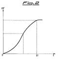
- Fig. 2 shows the relationship between the conduction time and the secondary voltage.
-
Fig. 1 shows an electric general diagram of the apparatus according to the invention.
-
An X-ray tube designated at RG is fed through a high voltage transformer AT for the emission of a beam f of X-rays by an emitting anode. More precisely the high voltage is present between the terminals S1 and S2 of the secondary winding, whereas a low voltage for the filament of the cathode K is obtained through an intermediate tap Si. The turn ratio n between the secondary and the primary windings is in the order of 7,000 to obtain a secondary voltage comprised between 0 and 300 kV.
-
The primary winding P1-P2 of the transformer AT is connected to a DC voltage Vcc supplied by a DC voltage supply PS through a switching or chopping circuit, known as chopper, designated at SW1 in the figure, and conceptually equivalent to a controlled switch that is periodically closed and opened by a control unit UC that generates output control pulses I having proper duration and frequency. Between the switch SW1, schematically shown in Fig. 1 as a semiconductor device having a control electrode, and the control unit UC, there is provided a drive circuit DR to supply the necessary power levels, schematically shown as two transistors TR1 and TR2 of complementary type, connected in series with each other and with the base electrodes connected together and driven by pulses I. The chopper circuit SW1 and the drive unit DR together form the power section of the device.
-
The source PS is schematically illustrated as comprising a rectifying bridge D1 connected to the 220 Volts main network, either directly or through a transformer (not shown), and a smoothing capacitor C1. It is to be pointed out that in the device of the invention, contrarily to those of the prior art, no voltage regulation is provided for.
-
The source PS can be of several known designs. In particular, although not expressely shown in the drawings, it can comprise a battery pack, in case rechargeable, to be used on locations without connections to the AC network.
-
The closing of the switch SW1 causes an increasing current to circulate in the primary winding P1-P2 that causes an induced voltage, also increasing, in the secondary winding as shown in Fig. 2 that represents the curve of the secondary voltage versus the closing duration or time-on of the switch SW1. The closure of the switch SW1 corresponds to the origin O and the switch is again opened before the time t1 corresponding to the saturation of the nucleus of the transformer AT. The control modalities for the switch SW1 will be described in detail later on.
-
According to the invention the transformer AT is provided with an additional low voltage sensing winding, designate at MS which is able to generate a voltage proportional to the high voltage effectively present at the secondary terminals S1-S2. A terminal of the winding MS is connected to ground whereas the other is connected to an input of a comparator CP1, the other input of which is connected to a first reference voltage obtained through a voltage source V1 and a potentiometer PR1. The potentiometer PR1 consents to the operator to set a predetermined value of the high voltage to be applied to the tube RG as a function of the characteristics of the article to be X-ray photographed.
-
The control unit further comprises a differential amplifier CP2 having an input connected to the return of the milliAmperes (mA) of the transformer AT, and the other input connected to a second reference voltage adjustable by the operator for adjusting the current in the filament of the tube RG, and hence the intensity of the emitted X-ray beam. Such second voltage is obtained for example through a voltage source V2 and a potentiometer PR2.
-
The output of the differential amplifier CP2 is connected to a voltage/frequency converter V/f transforming the error voltage with respect to the set value into a square waveform with a suitable repetition frequency. The output of the converter V/f is connected to the set input S of a resettable monostable multivibrator designated at MV, having the reset input R connected to the output of the comparator CP1. A R2-C2 network provides for the necessary time constant.
-
The working of the device is the following. The switch SW1 is periodically driven into conduction (on condition) by the pulse (wave edge) produced by the converter V/f. This causes a current pulse circulating in the primary winding and the generation of a high voltage pulse at the secondary winding of the transformer AT.
-
When the feedback voltage sensed by the sensing winding MS exceeds the value predetermined through PR1, the output of the comparator CP1 changes its logical state (output level) thus returning to zero the output Q of MV and thereby opening the switch SW1.
-
The duration of the conduction pulse (t-on) is not fixed, but rather changes with the changing of the set voltage and, during the conduction time, the high voltage increases as a function of the nucleus hysteresis and is interrupted when it reaches the predetermined value. This way the effects of the above considered variable intrinsic to the circuit, such as the cable lengths, the contact resistances, the temperature of the circuit, etc., do not influence the high voltage value any longer, but only determine a variation of the t-on duration.
-
The maintenance of a constant value of the secondary voltage in the first place allows for a regular working of the X-ray tube since its filament is regularly fed under any conditions.
-
Further, even when setting different values of the secondary voltage, the device of the invention correspondingly modifies the frequency of the pulses output from V/f, thus modifying the t-off time in such a manner as to return the (average) current in the filament to the requeste value.
-
Preferably the switch SW1 is implemented by means of semiconductor devices of the EXFET type that exhibit switching times in the order of 50 nanoseconds.
-
The switching frequency of the switch SW1 is preferably of about 800 Hz, anyhow such frequency can in general be comprised between 200 and 1,000 Hz.
-
The invention achieves the prefixed objects. Namely the sensing winding allows for sensing a voltage that is directly proportional to the high voltage effectively generated by the transformer. The voltage sensed by the sensing winding supplies the feedback that is used by the comparator for the comparison with the voltage set by the operator. When the DC voltage is obtained by rectifying the AC network voltage, there is no need of a regulation thereof.
-
Moreover, the time-on duration, i.e. the duration of the conduction pulse, is not fixed, but it changes when the set voltage changes. This way all the intrinsic variables of the circuit that are not easy to be monitored do not influence the final value of the high voltage, but only modify the time-on duration.
-
Finally, when a new value for the high voltage to be applied to the X-ray tube is set, the device of the invention is able to maintain the average current to the filament by simply varying the duration of the rest time, i.e. the time-off.
-
Although the invention has been described with particular reference to a preferred embodiment, the same is not to be considered limited to it, but extends to cover the obvious changes and modifications that will be evident to the skilled in the art.