EP0505505B1 - Interne strukturen aerodynamischer fühler - Google Patents
Interne strukturen aerodynamischer fühler Download PDFInfo
- Publication number
- EP0505505B1 EP0505505B1 EP91904298A EP91904298A EP0505505B1 EP 0505505 B1 EP0505505 B1 EP 0505505B1 EP 91904298 A EP91904298 A EP 91904298A EP 91904298 A EP91904298 A EP 91904298A EP 0505505 B1 EP0505505 B1 EP 0505505B1
- Authority
- EP
- European Patent Office
- Prior art keywords
- probe
- chambers
- bulkheads
- open
- port
- Prior art date
- Legal status (The legal status is an assumption and is not a legal conclusion. Google has not performed a legal analysis and makes no representation as to the accuracy of the status listed.)
- Expired - Lifetime
Links
- 239000000523 sample Substances 0.000 title claims abstract description 95
- 238000010276 construction Methods 0.000 title abstract description 10
- 230000007704 transition Effects 0.000 claims description 13
- 239000012530 fluid Substances 0.000 claims description 9
- 238000007789 sealing Methods 0.000 claims description 3
- 238000004519 manufacturing process Methods 0.000 abstract description 5
- 239000000463 material Substances 0.000 abstract description 3
- 230000003068 static effect Effects 0.000 description 5
- 239000002131 composite material Substances 0.000 description 3
- PXHVJJICTQNCMI-UHFFFAOYSA-N Nickel Chemical compound [Ni] PXHVJJICTQNCMI-UHFFFAOYSA-N 0.000 description 2
- 239000004568 cement Substances 0.000 description 2
- 238000000034 method Methods 0.000 description 2
- 230000009467 reduction Effects 0.000 description 2
- 238000005476 soldering Methods 0.000 description 2
- XLYOFNOQVPJJNP-UHFFFAOYSA-N water Substances O XLYOFNOQVPJJNP-UHFFFAOYSA-N 0.000 description 2
- 229910000990 Ni alloy Inorganic materials 0.000 description 1
- 239000000853 adhesive Substances 0.000 description 1
- 230000001070 adhesive effect Effects 0.000 description 1
- 230000000712 assembly Effects 0.000 description 1
- 238000000429 assembly Methods 0.000 description 1
- 238000005219 brazing Methods 0.000 description 1
- 230000008878 coupling Effects 0.000 description 1
- 238000010168 coupling process Methods 0.000 description 1
- 238000005859 coupling reaction Methods 0.000 description 1
- 238000002955 isolation Methods 0.000 description 1
- 239000002184 metal Substances 0.000 description 1
- 229910052751 metal Inorganic materials 0.000 description 1
- 229910001092 metal group alloy Inorganic materials 0.000 description 1
- 238000005549 size reduction Methods 0.000 description 1
- 229910000679 solder Inorganic materials 0.000 description 1
- 229920002994 synthetic fiber Polymers 0.000 description 1
- 238000003466 welding Methods 0.000 description 1
Images


Classifications
-
- G—PHYSICS
- G01—MEASURING; TESTING
- G01L—MEASURING FORCE, STRESS, TORQUE, WORK, MECHANICAL POWER, MECHANICAL EFFICIENCY, OR FLUID PRESSURE
- G01L19/00—Details of, or accessories for, apparatus for measuring steady or quasi-steady pressure of a fluent medium insofar as such details or accessories are not special to particular types of pressure gauges
- G01L19/0007—Fluidic connecting means
-
- G—PHYSICS
- G01—MEASURING; TESTING
- G01F—MEASURING VOLUME, VOLUME FLOW, MASS FLOW OR LIQUID LEVEL; METERING BY VOLUME
- G01F1/00—Measuring the volume flow or mass flow of fluid or fluent solid material wherein the fluid passes through a meter in a continuous flow
- G01F1/05—Measuring the volume flow or mass flow of fluid or fluent solid material wherein the fluid passes through a meter in a continuous flow by using mechanical effects
- G01F1/34—Measuring the volume flow or mass flow of fluid or fluent solid material wherein the fluid passes through a meter in a continuous flow by using mechanical effects by measuring pressure or differential pressure
- G01F1/36—Measuring the volume flow or mass flow of fluid or fluent solid material wherein the fluid passes through a meter in a continuous flow by using mechanical effects by measuring pressure or differential pressure the pressure or differential pressure being created by the use of flow constriction
- G01F1/40—Details of construction of the flow constriction devices
- G01F1/46—Pitot tubes
-
- G—PHYSICS
- G01—MEASURING; TESTING
- G01P—MEASURING LINEAR OR ANGULAR SPEED, ACCELERATION, DECELERATION, OR SHOCK; INDICATING PRESENCE, ABSENCE, OR DIRECTION, OF MOVEMENT
- G01P5/00—Measuring speed of fluids, e.g. of air stream; Measuring speed of bodies relative to fluids, e.g. of ship, of aircraft
- G01P5/14—Measuring speed of fluids, e.g. of air stream; Measuring speed of bodies relative to fluids, e.g. of ship, of aircraft by measuring differences of pressure in the fluid
- G01P5/16—Measuring speed of fluids, e.g. of air stream; Measuring speed of bodies relative to fluids, e.g. of ship, of aircraft by measuring differences of pressure in the fluid using Pitot tubes, e.g. Machmeter
- G01P5/165—Arrangements or constructions of Pitot tubes
Definitions
- the present invention relates to air data sensors constructed to maintain very compact outer dimensions and yet be relatively easy to manufacture.
- Multifunction probes are presently available that provide signals to determine air speed, static pressure, angle of attack and angle of side slip, and which have outer configurations that are designed to provide compensation for mounting configuration disturbances.
- WO-A-8607465 shows an aerodynamically compensated static pressure sensing probe that includes fixed internal bulkheads and tubes which are individually mounted on the interior of the probe barrel to provide individual chambers open to selected ports. The chambers are separated only by the bulkheads, which are individually fixed in place on the interior of the probe.
- US-A-4836019 discloses a probe for sensing air data parameters that has an insertable assembly on the interior of the probe that divides the interior into chambers using radial, annularly spaced divider sections to form longitudinally extending passageways or conduits for carrying fluid pressure from selected ports to suitable instrumentation.
- the divisions are annularly spaced and are not capable of having axially spaced ports opening to individual chambers at the same axial position.
- the present invention relates to air data sensing probes having an internal construction for carrying pressure signals from a plurality of ports on the probe to conduits at the probe support.
- the past arrangements of heater, bulkheads and individual tubes have increased the size of probes because of the need to be able to fabricate the assemblies.
- an air data sensing probe for determining air data parameters of fluid moving past the probe, and including an elongated tubular wall probe with a longitudinal axis and an inner surface, and a plurality of port means in the walls thereof for sensing pressures of a fluid relative to which the probe is moving, axially separated bulkheads arranged transverse to the longitudinal axis of the tubular wall probe defining at least first and second chambers, each open to at least one different port means from the other, and passageways for carrying fluid pressure open to each of the first and second chambers and extending longitudinally from a leading end of the probe toward a trailing end of the probe, characterised by a support fixedly mounting the bulkheads, and passageways in a separate assembly internal of the tubular wall probe, the bulkheads engaging and sealing on the inner surface of the tubular wall probe, and the assembly including wall means between the bulkheads forming the first and second chambers into part annular chambers.
- the probe then can be made smaller because, when the separate assembly is inserted into the interior of the probe, substantially all of the cross section of the probe is used for routing the pressure signal carrying passageways and the heater elements while sealing and isolating the ports from one another with the bulkheads.
- the invention provides a probe which can be made small in diameter so that it has less drag, weight, and radar cross section.
- Construction can be modular, since the internal assembly of bulkheads and tubes can be the same for probes which have the same internal size but which have different outer surface configurations. With the reduction in size achievable, it becomes practical to use moulded composite type materials in place of metal for the probe and for other structural parts.
- the invention provides isolation of ports that are at the same axial location in fore and aft directions by use of the bulkheads and part annular chambers to permit individual sensing of pressures at ports at the same axial location using a separate assembly that can be inserted into the interior of the probe without individually mounting each of the bulkheads and individual tubes.
- the present invention provides structure for coupling pressure from the pressure sensing ports to pressure output tubes so that the internal construction can be made with relatively small diameter, precision made standard parts that will be usable on a wide number of different models of air data sensors.
- the probe of the present invention can further include heaters that are mounted around a central support or passageway which can be used for receiving pitot pressure. Additionally, the placement of the heaters in one form of the invention permits use of materials other than nickel or metal alloys for the tube itself.
- the separate assembly comprises a concentric tube bundle of a plurality of individual tubes, with a connection component having multiple isolated passageways at the base end of the probe barrel.
- Two embodiments of the invention are shown, one which provides for pressure passageways being formed by individual tubular members mounted around a central tube that receives the pitot pressure (usually from a front facing, centered or axial port).
- a second form of the invention utilizes a single plug member having grooves therein that define pressure carrying conduits, and a central passageway for the pitot pressure.
- the unitary assembly then has a multiple passageway isolated outlet assembly at its rearward portion, where the probe is mounted to the air vehicle, that provides for connection to remote conduits that lead to the specific instruments or sensors that are desired.
- the present invention permits very small, compact probes wherein the size limitations caused by conventional fabrication techniques are minimized.
- the present construction permits the sensing ports to be placed much closer together and closer to the leading end of the probe, so that short probes, where the sensing ports are on a tapered forward portion of the barrel, can be connected to their respective instruments through the present passageway assembly very efficiently and effectively.
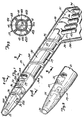
- a multifunction air data sensor or probe indicated generally at 20 as shown is of the type that can measure angle of attack, mach number, and provide readings that indicate static pressure.
- the air data sensor includes a barrel or shell indicated generally at 21 which is formed in its main portion as an elongated cylinder 21A, having a central longitudinal axis 22 ( Figure 3).
- the forward end 23 of the air data sensor barrel or shell 21 has a tapered forward surface 24 that has a pitot port 25 for sensing impact pressure at the forward (leading) end thereof.
- the pitot port 25 is a sharp-edged port.
- the tapered surface 24 expands in downstream direction relative to the longitudinal axis 22 for a selected distance.
- a small hole 25A may be used to drain water which enters port 25.
- a surface section may be formed to have a greater included angle than the section 24, for providing a compensating pressure disturbance, as is known in the prior art.
- the surface 24 joins the cylindrical section 21A.
- the shell or barrel 21 is mounted onto a mounting strut 30 that is adapted to be mounted onto the side of an aircraft.
- the longitudinal axis 22 of the barrel is held in a known position relative to the aircraft axis so that changes in the orientation of the probe longitudinal axis 22 relative to a horizontal reference plane will give an indication of angle of attack of the aircraft.
- the angle of side slip also may be determined with a probe using the interior manifold construction of the present invention by providing appropriately positioned sensing ports.
- a first set of ports 31 and 32 positioned at the top and bottom of a barrel or shell 21, and there is a port 33 that has an axis 90° to the axes of ports 31 and 32.
- the axes of ports 31 and 32 are coincident axes. Measuring side slip would require a port to be provided on the same axis as the axis of port 33 but on the opposite side of the probe from port 33.
- the port 33 is used to provide a static pressure signal.
- the ports 31 and 32 are used for individually obtaining pressure signals that indicate the angle of attack of the aircraft. With proper compensation and calculation using derived formulas known in the prior art, angle of attack, static pressure, and with the pitot pressure, mach number can be obtained from the signals.
- the pressure signals from ports 31 and 32 are kept isolated or separated by suitable blocks or walls 34 and 34A which are provided between the ports which are on common axes. Wall 34A is on the opposite side of the probe from block 34.
- the pressure signals from ports 31, 32 and 33, and from pitot port 25 are transmitted to remote conduits for use in a desired manner through a multiple passageway assembly indicated generally at 35 which includes bulkhead disks 26,36,36A and 39 that fit within the inner surface of the barrel, including the tapered forward section.
- Bulkheads and blocks or walls 34 and 34A form chambers indicated at 31A-33A in Figure 2A. These chambers open into individual tubes of a multiple tube bundle 37 which is rearwardly of a bulkhead 36A.
- a central tube 38 forms a support for the bulkheads and the tube bundle 37.
- Bulkhead 39 forms a pitot pressure chamber 40 to the rear of pitot port 25.
- the tube 38 opens to the chamber 40 through one or more ports 38A and is thus connected to the pitot port.
- the tube bundle 37 is shown in Figure 3, and is formed of a plurality of individual part annular cross section tubes 41, 42 (for the ports 31 and 32), and 43 (for the port 33).
- a tube 44 that would be used as a port for measuring angle of side slip is provided, but in this form of the invention this tube does not carry a pressure signal.
- the tubes have outer part-cylindrical walls indicated at 41A-44A and define interior passageways 41B-44B.
- the tubes also have radially extending walls and part annular inner walls that fit around the tube 38 that carries the pressure from the pitot port.
- the tubes 41-44 form cylindrical-shaped bundle 37 as shown in Figure 1.
- the tubes can be suitably joined together by welding or in another suitable manner to form tube bundle 37.
- the passageways of the tube bundle form a multiple passageway portion that is concentric with the central axis 22, because the tubes are formed around and are concentric with the tube 38 carrying the pitot pressure.
- the tube bundle 37 and tube 38 substantially fill an internal cross section with no wasted space between the pressure passageways. This efficient use of internal cross section allows for a reduced probe cross section with corresponding reductions in drag and radar cross section.
- Assembly 35 includes a transition section 50 for connection of conduits or tubes carrying pressure signals from the tubes in bundle 37 to instrumentation on the aircraft.
- the transition section 50 forms part of the assembly 35 and comprises an outer sleeve 51 that wraps around the tube bundle 37.
- the sleeve 51 is not fully annular, as can be seen in Figures 4-8 in particular, but is formed to enclose the tubes 41-44 which are terminated and connected to conduits at different axial locations along the longitudinal axis 22.
- transition section 50 has part annular walls of bulkheads to seal off the rear openings of the individual tubes 41-44 at different axial positions so that the pressure signal from each of the individual tubes 41-44 are isolated or seal from one another and can be provided to an individual line or conduit leading through the strut to remote instruments.
- Figure 4 is rotated 90° from Figures 1 and 3 so tube 44 is on the bottom and the connection conduits extend downwardly in Figures 5-8.
- the transition section has a bulkhead wall 55 forming a quarter of a circular segment that forms a chamber 58 to the rear of the tube 44.
- a pressure port is defined in the wall of the sleeve 51 and a pressure output line or conduit 57 is connected to the chamber formed by bulkhead wall 55.
- the tube 44 ends just rearwardly of front edge 56 of sleeve 51.
- Chamber 58 is formed by sleeve 51 and bulkhead wall 55 and the walls of the adjacent tubes 41 and 42, and tube 38.
- a second tube for example the tube 41, is terminated in a chamber formed with a half-circle bulkhead wall 60 shown in Figure 6.
- a pressure signal can be taken off tube 41 through an output line or conduit 62.
- Half-circle bulkhead 60 closes off a chamber 61 and that extends about 180°.
- Tube 41 terminates rearwardly of bulkhead wall 55, and walls 55 and 60 define the chamber 61 together with the wall of sleeve 51 and side walls of tubes 43 and 42.
- Tube 41 opens into chamber 61, and line 62 also opens to chamber 61.
- the bulkhead walls are soldered or otherwise sealed in place. If synthetic materials are used, the bulkhead walls can be cemented into position.
- a third tube extends beyond the bulkhead 60, in downstream direction and opens to a chamber 67 formed at the rear thereof by a three-quarter circular section bulkhead wall 65 and at the front by bulkhead wall 60.
- the sleeve 51 and the side walls of tube 42 also define the walls of chamber 67 along with the outer surface of tube 38.
- the fluid pressure from tube 43 is transferred to a line or conduit 66 attached to sleeve 51.
- the fourth tube for example tube 42, extends downstream toward the rear end of the manifold transition section 50.
- the tube 42 ends rearwardly of bulkhead wall 66Aand opens into a chamber 71 formed by a full circle annular bulkhead 70 and wall 66A.
- the chamber 71 is an annular chamber and a line or conduit 73 is open to chamber 71 through sleeve 51. Line 73 leads to remote instruments.
- the pitot pressure carrying tube 38 is connected at the rear of the transition section 50, to a conduit or line 74 which leads to remote instruments.
- the bulkhead walls 55, 60, 65, and 70 are all fitted around the line or tube 38 and the tube 38 forms a central support for the manifold assembly.
- the manifold assembly 35 can be slipped into the outer barrel quite easily, and can be manufactured separately from the shell or barrel. It is more simple to manufacture and seal the bulkheads and tubes outside of the barrel.
- a deicing heater indicated generally at 75 can be wrapped on the outside of the tube bundle 37 and be supported thereon, and suitable leads are then connected to wires extending through the strut 30 for power. Since the outer shell or barrel does not have to have the heater embedded in it, or otherwise fixed to its wall, the barrel can be made of composite materials, as can the tube bundle 37.
- the construction makes it possible to have smaller outer barrels, because of the simplicity of constructing the manifold assembly and slipping it into place before securing it to the barrel or shell in a suitable manner.
- the manifold assembly can be secured with various cements or adhesives, or by soldering or brazing in place if desired.
- the front bulkheads 26, 36 and 36A can be slid against the inner surface of the barrel and fitted to provide for adequate pressure seals.
- a short probe again is used with an internal manifold, and as can be seen in Figure 9, a short probe indicated generally at 80 is made to have a generally tapered outer surface 81, and a sharp-edged pitot port 82 at the leading end thereof.
- the probe has a mounting hub 83 at its rearward end, that can be used for mounting the probe barrel onto a suitable transition section or cap and support structure such as a strut.
- This probe also has a pair of ports 84 and 85 on the top and bottom of the probe, which have axes that lie on a common plane at a first location along the longitudinal axis 86. Additionally, in this particular probe, ports 87 and 88, respectively, are formed through the wall of the barrel of the probe downstream from and aligning with the ports 84 and 85 in longitudinal direction. The ports open through the wall of the probe. A bore 90 is defined in the center of the probe barrel.
- the leading end of the probe also has a bore indicated at 91 therein that opens to a central leading bore 92 carrying the pressure signal from the port 82.
- a helically wound electrical heater 93 is slipped into bore 91 and has an open central passageway of about the same size as bore 92.
- the heater conduit can be held in place in a suitable manner and the bore 90 mounts a multiple passageway assembly indicated generally at 94 which in this form of the invention comprises a unitary block that has an interior bore 95 of size to receive the heater 93 and provide a passageway for pitot pressure.
- the ports 84, 85, 88 and 87 are made so that they open to the bore 90, and are then suitably isolatingly connected to passageways in the assembly 94.
- the port 84 opens into a part annular passageway or chamber 100 as can be seen in Figure 10.
- a front wall or bulkhead 101 closes off passageway 100.
- the part annular passageway 100 is formed in part by an interior wall section 101A and extends partway around the central axis 86.
- a longitudinally extending passageway 105 that is centered at an approximately horizontal plane indicated at 96 in Figure 10 opens to passageway 100.
- Port 85 which is diametrically opposite from the port 84, opens into a part annular passageway 107, which also extends around the central axis 86.
- a passageway 108 that extends longitudinally along the barrel opens to part annular passageway 107.
- Passageway 108 can also be seen in Figure 11, which is a section taken through the axes of ports 87 and 88.
- the rear of the passageways 100 and 107 are formed by a bulkhead wall 110.
- Ports 87 and 88 open into separate longitudinally extending passageways, as can be seen in Figure 11.
- the port 87 opens into a passageway 112 formed or defined directly in the assembly 94 through bulkhead wall 110.
- Passageway 112 extends longitudinally and is separated from and centered 90° from the passageways 108 and 105.
- the port 88 opens into a passageway 114 that also extends longitudinally through bulkhead wall 110 and is diametrically opposite from the passageway 112.
- a pair of guide ribs indicated at 120,120 are formed between the adjacent passageways between bulkhead walls 101 and 110 and serve to seal the passageways from each other, so the pressure signals are kept separate or isolated and to provide surfaces that will slide on the interior of the bore 90, and support the manifold properly for use.
- These guide ribs 120 are formed by the respective adjacent passageways and a longitudinally extending slot 121 (for solder) formed between each set of ribs.
- the passageways can easily be connected into a housing or cap 125 that fits over the shoulder or hub 83, for example.
- the cap has suitable passageways that mate with the respective passageways 92, 105, 108, 112 and 114.
- the individual passageways open to conduits shown at 126 for the passageway 112; 127 for the passageway 105; 128 for the passageway 114; and 129 for the passageway 108.
- a conduit 131 is used for carrying the pitot pressure from the passageway 92 to remote instruments.
- a small opening 95A can be provided to drain water from the pitot passageway.
- conduits can be run down a strut for the air data sensing probe, or if the probe is mounted on a boom or similar support, the conduits can be run directly through the boom or support that might fit on the hub 83.
- a very short and small diameter probe can be made because the internal manifold assembly can be separately manufactured and slid into place, and fastened securely with suitable methods, such as soldering or with suitable cements. There is substantially no wasted space in the cross section. It is not necessary to have a large number of separated bulkheads with individual tubes carrying the various pressure signals.
Landscapes
- Physics & Mathematics (AREA)
- General Physics & Mathematics (AREA)
- Engineering & Computer Science (AREA)
- Aviation & Aerospace Engineering (AREA)
- Fluid Mechanics (AREA)
- Measuring Fluid Pressure (AREA)
- Motor Or Generator Cooling System (AREA)
Claims (12)
- Ein Luftdatenerfassungsfühler (20, 80) zur Bestimmung von Luftdatenparametern von sich an dem Fühler (20, 80) vorbeibewegendem Fluid und das einen länglichen Fühler (20, 80) mit röhrenförmiger Wand, mit einer Längsachse (22, 86) und einer inneren Oberfläche, und eine Vielzahl von Öffnungsvorrichtungen (31, 32, 84, 85), in dessen Wänden zur Erfassung von Drücken eines Fluids, relativ zu dem sich der Fühler (20, 80) bewegt, axial getrennte Trennwände (26, 36, 36A, 39, 101, 110), die quer zur Längsachse des Fühlers (20, 80) mit röhrenförmiger Wand angeordnet sind und zumindest erste und zweite Kammern (31A, 32A, 100, 107) abgrenzen, die je zu mindestens einer gegenüber der anderen unterschiedlichen Öffnungsvorrichtung (31, 32, 84, 85) offen sind, und Durchtrittsausnehmungen (41B, 42B, 105, 108) zum Führen von Fluiddruck aufweist, die zu jeder der ersten und zweiten Kammern (31A, 32A, 100, 107) offen sind und sich von einem vorderen Ende (23) des Fühlers (20, 80) zu einem hinteren Ende des Fühlers (20, 80) längs erstrecken, gekennzeichnet durch eine Abstützung (38, 94), die die Trennwände (26, 36, 36A, 39, 101, 110) fest lagert, und Durchtrittsausnehmungen (41B, 42B, 105, 108) in einer separaten Anordnung innerhalb des Fühlers (20, 80) mit röhrenförmiger Wand, wobei die Trennwände (26, 36, 36A, 39, 101, 110) auf der inneren Oberfläche des Fühlers (20, 80) mit röhrenförmiger Wand in Eingriff stehen und abdichten, und die Anordnung Wandvorrichtungen (34, 120) zwischen den Trennwänden (26, 36, 36A, 39, 101, 110) aufweist, die die ersten und zweiten Kammern in teilweise ringförmigen Kammern ausbilden.
- Fühler nach Anspruch 1, dadurch gekennzeichnet, daß die Trennwände (26, 36, 36A, 39, 101, 110) eine dritte Kammer (33A, 112) abgrenzen, die von den ersten und zweiten Kammern axial beabstandet ist, wobei jede ausgebildete Kammer zu dieser eine separate Ausnehmungsöffnung (31, 32, 33, 84, 85, 87) aufweist.
- Fühler nach Anspruch 1 oder 2, dadurch gekennzeichnet, daß die sich längs erstreckenden Durchtrittsausnehmungen einzelne Rohrelemente (41, 42, 43) aufweisen, die als ein Bündel (37) abgestützt sind und Enden aufweisen, die zu den jeweiligen Kammern (31A, 32A, 33A) offen sind.
- Fühler nach Anspruch 1, 2 oder 3 und ein Übergangsabschnitt (50) an einem hinteren Ende des Fühlers (20), wobei der Übergangsabschnitt (50) eine Muffe (51) aufweist, die die sich längs erstreckenden Durchtrittsausnehmungen (41B, 42B, 43B, 44B) umgibt, Wandvorrichtungen (55, 60, 65, 70) zum einzelnen Abschluß jeder der sich längs erstreckenden Durchtrittsausnehmungen in teilweise ringförmige Übergangskammern (58, 61, 67), die an dem Übergangsabschnitt (50) ausgebildet sind, und Leitungen (57, 62, 66, 73), die zu jeder der ringförmigen Übergangskammern offen sind.
- Fühler nach Anspruch 4, dadurch gekennzeichnet, daß die Leitungen (57, 62, 66, 73) Achsen aufweisen, die im allgemeinen entlang einer gemeinsamen Ebene liegen, die sich dort erstreckt, wo die Leitungen zu den teilweise ringförmigen Übergangskammern offen sind.
- Fühler nach einem der Ansprüche 1 bis 5, dadurch gekennzeichnet, daß die Abstützung (38) ein Pitotdruck leitendes Rohr (38) aufweist, auf dem die Trennwände (26, 36, 36A, 39) befestigt sind, wobei sich das Pitotdruck leitende Rohr (38) in das vordere Ende (23) des Fühlers (20) erstreckt, wobei der Fühler (20) eine scharfkantige Mündung (25) in sich aufweist, die zu dem Pitotdruck leitenden Rohr (38) offen ist.
- Fühler nach einem der Ansprüche 1 bis 5, dadurch gekennzeichnet, daß die Abstützung eine im wesentlichen starre Leitung (38) aufweist, und die sich längs erstreckenden Durchtrittsausnehmungen (41B, 42B) teilweise ringförmige Rohrvorrichtungen (41, 42) aufweisen, die an der im wesentlichen starren Leitung (38) angebracht sind und diese umgeben.
- Fühler nach einem der Ansprüche 1 bis 5, dadurch gekennzeichnet, daß die Anordnung eine separat hergestellte Anordnung (94) ist, die in das Innere des Fühlers (80) mit ringförmiger Wand zum Leiten einzelner Drücke von jeder der Öffnungen eingebracht werden kann, und erste Abschnitte aufweist, die eine mittlere Öffnung (95) entlang der Längsachse (86) der Anordnung abgrenzt, wobei die Trennwände separate zweite ringförmig beabstandete zweite Kammern (112, 114) ausbilden, die von den ersten und zweiten Kammern (100, 107) axial beabstandet sind, und wobei jede der zweiten ringförmig beabstandeten zweiten Kammern (112, 114) zu mindestens einer separaten Öffnung (87, 88) in dem Fühler (80) mit ringförmiger Wand offen ist.
- Fühler nach Anspruch 8 und eine Pitotöffnung (82), die in einem vorderen Ende des Fühlers festgelegt ist, um ein Pitotdrucksignal zu liefern, wobei die mittlere Öffnung (90) zur Pitotöffnung (82) offen ist und ein Pitotdrucksignal zu einem rückwärtigen Ende des Fühlers (80) leitet.
- Fühler nach einem der Ansprüche 1 bis 5 oder 8, dadurch gekennzeichnet, daß die sich längs erstreckenden Durchtrittsausnehmungen (105, 108) ein einheitliches Blockelement (94) aufweisen, das äußere Oberflächenabschnitte aufweist, die mit der inneren Oberfläche des verlängerten Fühlers (80) in Eingriff stehen, wobei das Blockelement (94) in sich ausgebildete und sich entlang diesem längs erstreckende Aussparungen (105, 108) aufweist, wobei die Aussparungen (105, 108) an ihrer äußeren Oberfläche durch die innere Oberfläche des Fühlers mit ringförmiger Wand abgeschlossen sind, und eine mittlere Bohrung (92) in dem einheitlichen Element zu einer vorderen Pitotdrucköffnung (82) am vorderen Ende des Fühlers (80) offen ist.
- Fühler nach einem der Ansprüche 1 bis 5 oder 8 bis 10, dadurch gekennzeichnet, daß die separate Anordnung und die sich längs erstreckenden Durchtrittsausnehmungen (105, 108) einen einheitlichen Block (94), der in sich ausgebildete und zu einer äußeren Oberfläche des Blocks offene und sich entlang diesem längs erstreckende Aussparungen (105, 108) aufweist, wobei die Aussparungen (105, 108) an ihren äußeren Oberflächen durch eine innere Oberfläche des Fühlers mit ringförmiger Wand abgeschlossen sind, und eine mittlere Bohrung (95) in dem einheitlichen Block und eine schraubenförmig gewickelte Heizvorrichtung (93) aufweisen, die in der mittleren Bohrung (95) angebracht ist.
- Fühler nach Anspruch 11, dadurch gekennzeichnet, daß die schraubenförmig gewickelte Heizvorrichtung (93) mit einer Oberfläche in Eingriff steht, die die Bohrung (95) abgrenzt, und die schraubenförmig gewickelte Heizvorrichtung (93) einen offenen mittleren Abschnitt (92) zum Leiten von Fluiddruck aufweist.
Applications Claiming Priority (3)
| Application Number | Priority Date | Filing Date | Title |
|---|---|---|---|
| US451437 | 1989-12-15 | ||
| US07/451,437 US5046360A (en) | 1989-12-15 | 1989-12-15 | Aerodynamic probe internal constructions |
| PCT/US1990/006567 WO1991009274A1 (en) | 1989-12-15 | 1990-11-09 | Aerodynamic probe internal constructions |
Publications (3)
| Publication Number | Publication Date |
|---|---|
| EP0505505A1 EP0505505A1 (de) | 1992-09-30 |
| EP0505505A4 EP0505505A4 (en) | 1993-01-13 |
| EP0505505B1 true EP0505505B1 (de) | 1995-08-23 |
Family
ID=23792213
Family Applications (1)
| Application Number | Title | Priority Date | Filing Date |
|---|---|---|---|
| EP91904298A Expired - Lifetime EP0505505B1 (de) | 1989-12-15 | 1990-11-09 | Interne strukturen aerodynamischer fühler |
Country Status (10)
| Country | Link |
|---|---|
| US (1) | US5046360A (de) |
| EP (1) | EP0505505B1 (de) |
| JP (1) | JP2851163B2 (de) |
| CN (1) | CN1029029C (de) |
| BR (1) | BR9007910A (de) |
| CA (1) | CA2069110A1 (de) |
| DE (1) | DE69021890T2 (de) |
| IL (1) | IL96190A (de) |
| RU (1) | RU2062988C1 (de) |
| WO (1) | WO1991009274A1 (de) |
Families Citing this family (44)
| Publication number | Priority date | Publication date | Assignee | Title |
|---|---|---|---|---|
| US5552576A (en) * | 1992-02-21 | 1996-09-03 | The Bf Goodrich Company | Modular drainmast for aircraft |
| US5290996A (en) * | 1992-02-21 | 1994-03-01 | The B. F. Goodrich Company | Modular drainmast for aircraft |
| US5337602A (en) * | 1992-08-24 | 1994-08-16 | Gibson Michael E | Pitot static tube having accessible heating element |
| US6098474A (en) * | 1997-09-09 | 2000-08-08 | Rosemont Aerospace Inc. | Enclosure for position transmitter |
| US6029361A (en) * | 1998-03-25 | 2000-02-29 | Ultratech Stepper, Inc. | Air-guage nozzle probe structure for microlithographic image focusing |
| US6012331A (en) * | 1998-07-02 | 2000-01-11 | Avionics Specialties, Inc. | Multifunction aircraft probes |
| FR2856880B1 (fr) * | 2003-06-27 | 2005-09-23 | Auxitrol Sa | Resistance chauffante notamment pour la chauffe d'une piece massive telle qu'une sonde de temperature et/ou de prise de pression |
| US7137297B2 (en) * | 2004-05-11 | 2006-11-21 | Harco Laboratories, Inc. | System and method for non-contact forming of parts to a fluid sensor assembly |
| US8930062B2 (en) * | 2009-04-21 | 2015-01-06 | Indian Space Research Organisation | System and method for detecting and isolating faults in pressure sensing of flush air data system (FADS) |
| ES2394558B1 (es) * | 2010-01-18 | 2013-12-12 | Eads Construcciones Aeronáuticas, S.A. | Dispositivo de soporte para sonda. |
| FR2960596B1 (fr) | 2010-05-25 | 2014-05-02 | Turbomeca | Dispositif d'acquisition/distribution multipoints de fluide, en particulier sonde de prise de pression dans une entree d'air de turbomachine |
| US8863590B2 (en) * | 2012-03-26 | 2014-10-21 | General Electric Company | Large diameter flow-through Kiel-style pressure probe for high moisture applications |
| EP2728364B1 (de) | 2012-10-31 | 2019-04-17 | Rosemount Aerospace Inc. | Eisresistente Pitot-Sonde |
| CN103344486A (zh) * | 2013-07-04 | 2013-10-09 | 武汉大学 | 一种再热裂纹插销试验机加热装置 |
| US10585109B2 (en) | 2014-06-02 | 2020-03-10 | University Of Kansas | Systems, methods, and devices for fluid data sensing |
| US9541429B2 (en) | 2014-06-02 | 2017-01-10 | University Of Kansas | Systems, methods, and devices for fluid data sensing |
| US11209330B2 (en) | 2015-03-23 | 2021-12-28 | Rosemount Aerospace Inc. | Corrosion resistant sleeve for an air data probe |
| US10227139B2 (en) * | 2015-03-23 | 2019-03-12 | Rosemount Aerospace Inc. | Heated air data probes |
| US20190316946A9 (en) * | 2015-03-23 | 2019-10-17 | Rosemount Aerospace Inc. | Corrosion resistant sleeve for an air data probe |
| US9606137B2 (en) | 2015-06-17 | 2017-03-28 | Rosemount Aerospace Inc. | Enhancements for differential-pressure-driven fluid flows |
| US9664542B2 (en) * | 2015-08-20 | 2017-05-30 | Honeywell International Inc. | Systems and methods for additive manufacturing for air data probes |
| US9891083B2 (en) | 2016-01-08 | 2018-02-13 | Honeywell International Inc. | Probe tip for air data probe |
| US10384787B2 (en) * | 2016-06-23 | 2019-08-20 | Honeywell International Inc. | Forming an air data probe from a porous cover and brazing material |
| CN107543649B (zh) * | 2016-06-26 | 2023-10-24 | 成都凯天电子股份有限公司 | 热气除冰总压受感器 |
| US10197588B2 (en) * | 2016-11-09 | 2019-02-05 | Honeywell International Inc. | Thin film heating systems for air data probes |
| US11414195B2 (en) | 2018-03-23 | 2022-08-16 | Rosemount Aerospace Inc. | Surface modified heater assembly |
| US10564173B2 (en) * | 2018-05-09 | 2020-02-18 | Rosemount Aerospace, Inc. | Pitot-static probe with pneumatic angle-of-attack sensor |
| US11262227B2 (en) | 2018-10-05 | 2022-03-01 | Rosemount Aerospace Inc. | Pitot tube heater assembly |
| US11002754B2 (en) | 2018-11-06 | 2021-05-11 | Rosemount Aerospace Inc. | Pitot probe with mandrel and pressure swaged outer shell |
| CN109470401B (zh) * | 2018-11-08 | 2021-09-07 | 中国航天空气动力技术研究院 | 一种带有迎侧角度解算的直杆型空速管 |
| CN109877314B (zh) * | 2018-12-05 | 2021-11-23 | 太原航空仪表有限公司 | 一种多功能大气数据探头及增材制造方法 |
| US10823753B2 (en) * | 2018-12-14 | 2020-11-03 | Rosemount Aerospace Inc. | Air data probe with optical pressure integration |
| CA3067550A1 (en) | 2019-01-17 | 2020-07-17 | Goodrich Corporation | Pitot tube |
| US10884014B2 (en) | 2019-03-25 | 2021-01-05 | Rosemount Aerospace Inc. | Air data probe with fully-encapsulated heater |
| US11428707B2 (en) | 2019-06-14 | 2022-08-30 | Rosemount Aerospace Inc. | Air data probe with weld sealed insert |
| CN112649621B (zh) * | 2019-10-11 | 2024-05-14 | 上海峰飞航空科技有限公司 | 一体式加热空速管及包含其的无人机 |
| CN111157759B (zh) * | 2019-12-24 | 2022-11-04 | 太原航空仪表有限公司 | 一种固定压差式攻角传感器及使用方法 |
| BR112022016815A2 (pt) | 2020-02-25 | 2022-10-11 | Rosemount Aerospace Inc | Sensor de ângulo de ataque |
| CN113532788B (zh) * | 2021-07-22 | 2025-07-01 | 北京航空航天大学 | 一种测量转静间端区二次流的小扰动高分辨率动态探针 |
| US11624637B1 (en) | 2021-10-01 | 2023-04-11 | Rosemount Aerospace Inc | Air data probe with integrated heater bore and features |
| US11662235B2 (en) | 2021-10-01 | 2023-05-30 | Rosemount Aerospace Inc. | Air data probe with enhanced conduction integrated heater bore and features |
| US12214887B2 (en) | 2022-01-27 | 2025-02-04 | Hamilton Sundstrand Corporation | Environmental control system including humidity sensor |
| CN115892490B (zh) * | 2022-11-14 | 2025-06-24 | 南京航空航天大学 | 大气数据探头支臂及大气数据探测系统 |
| US12455295B2 (en) * | 2023-08-17 | 2025-10-28 | Rosemount Aerospace Inc. | Conformal multi-function air-data probes |
Citations (1)
| Publication number | Priority date | Publication date | Assignee | Title |
|---|---|---|---|---|
| WO1986007465A1 (en) * | 1985-06-04 | 1986-12-18 | Rosemount Inc. | Family of aerodynamically compensated multiple static pressure tubes |
Family Cites Families (7)
| Publication number | Priority date | Publication date | Assignee | Title |
|---|---|---|---|---|
| US2381327A (en) * | 1944-02-19 | 1945-08-07 | Westinghouse Electric Corp | Pitot static air-speed indicator |
| US2977793A (en) * | 1957-02-25 | 1961-04-04 | Specialties Inc | Pneumatic probe assembly for detecting airstream direction |
| US2984107A (en) * | 1957-09-16 | 1961-05-16 | Us Industries Inc | Pitot static tube |
| US3482445A (en) * | 1968-04-25 | 1969-12-09 | Rosemount Eng Co Ltd | Strut mounted dual static tube |
| US4192178A (en) * | 1978-06-29 | 1980-03-11 | Westinghouse Electric Corp. | Apparatus for determining stagnation pressure, static pressure, pitch angle, and yaw angle of elastic fluid |
| US4275603A (en) * | 1979-11-23 | 1981-06-30 | The Boeing Company | Indirectly heated aircraft probes and masts |
| US4836019A (en) * | 1987-08-27 | 1989-06-06 | Rosemount Inc. | Compact air data sensor |
-
1989
- 1989-12-15 US US07/451,437 patent/US5046360A/en not_active Expired - Fee Related
-
1990
- 1990-10-31 IL IL96190A patent/IL96190A/xx not_active IP Right Cessation
- 1990-11-08 CA CA002069110A patent/CA2069110A1/en not_active Abandoned
- 1990-11-09 RU SU905052454A patent/RU2062988C1/ru active
- 1990-11-09 WO PCT/US1990/006567 patent/WO1991009274A1/en not_active Ceased
- 1990-11-09 JP JP3504321A patent/JP2851163B2/ja not_active Expired - Fee Related
- 1990-11-09 EP EP91904298A patent/EP0505505B1/de not_active Expired - Lifetime
- 1990-11-09 BR BR909007910A patent/BR9007910A/pt not_active IP Right Cessation
- 1990-11-09 DE DE69021890T patent/DE69021890T2/de not_active Expired - Fee Related
- 1990-12-13 CN CN90109966.XA patent/CN1029029C/zh not_active Expired - Fee Related
Patent Citations (1)
| Publication number | Priority date | Publication date | Assignee | Title |
|---|---|---|---|---|
| WO1986007465A1 (en) * | 1985-06-04 | 1986-12-18 | Rosemount Inc. | Family of aerodynamically compensated multiple static pressure tubes |
Also Published As
| Publication number | Publication date |
|---|---|
| IL96190A (en) | 1992-11-15 |
| CN1029029C (zh) | 1995-06-21 |
| US5046360A (en) | 1991-09-10 |
| JPH05508704A (ja) | 1993-12-02 |
| JP2851163B2 (ja) | 1999-01-27 |
| RU2062988C1 (ru) | 1996-06-27 |
| BR9007910A (pt) | 1992-08-25 |
| CN1052550A (zh) | 1991-06-26 |
| EP0505505A1 (de) | 1992-09-30 |
| CA2069110A1 (en) | 1991-06-16 |
| EP0505505A4 (en) | 1993-01-13 |
| DE69021890T2 (de) | 1996-04-25 |
| IL96190A0 (en) | 1991-07-18 |
| DE69021890D1 (de) | 1995-09-28 |
| WO1991009274A1 (en) | 1991-06-27 |
Similar Documents
| Publication | Publication Date | Title |
|---|---|---|
| EP0505505B1 (de) | Interne strukturen aerodynamischer fühler | |
| US4378696A (en) | Pressure sensor for determining airspeed altitude and angle of attack | |
| US4096744A (en) | Pressure sensor for determining airspeed, altitude and angle of attack | |
| US4836019A (en) | Compact air data sensor | |
| US5544526A (en) | Combined aircraft angle of attack and dynamic/static pressure sensor assembly | |
| CN106840591B (zh) | 一种直接测量喷流推力的试验装置 | |
| US4821566A (en) | Air data measurement apparatus | |
| EP0229534A2 (de) | Kombinationsdrucksonde | |
| US4672846A (en) | Multi-function pressure probe for aircraft | |
| CA2252867A1 (en) | Flow meter pitot tube with temperature sensor | |
| EP1092126B1 (de) | Verbesserte multifunktionsflugzeugsonden | |
| US3585859A (en) | Aerodynamically compensated static pressure tube | |
| EP0158664B1 (de) | Vorrichtung zur korrektur des barometerdrucks verursacht durch fehler hervorgerufen durch windrichtung und geschwindigkeit | |
| WO1986007465A1 (en) | Family of aerodynamically compensated multiple static pressure tubes | |
| US4872807A (en) | Static pressure system for gas turbine engines | |
| US5756892A (en) | Apparatus for measuring ambient pressure within a gaseous flow field | |
| US4425807A (en) | Flow measuring device with constant flow coefficient | |
| CN101512215B (zh) | 具有集成的压力传感器的液压/气动加载阀 | |
| WO1981001331A1 (en) | Flow device for sensors | |
| CN107796452A (zh) | 气体流量计 | |
| JPH07110274A (ja) | 水冷式多チャンネル圧力計測センサ | |
| CN209356526U (zh) | 一种基于边界层设计的测速多腔体装置 | |
| JPH0236093Y2 (de) | ||
| SU815503A1 (ru) | Турбинный расходомер | |
| CN104296815A (zh) | 一种高精度液体流量计 |
Legal Events
| Date | Code | Title | Description |
|---|---|---|---|
| PUAI | Public reference made under article 153(3) epc to a published international application that has entered the european phase |
Free format text: ORIGINAL CODE: 0009012 |
|
| 17P | Request for examination filed |
Effective date: 19920518 |
|
| AK | Designated contracting states |
Kind code of ref document: A1 Designated state(s): DE FR GB IT SE |
|
| A4 | Supplementary search report drawn up and despatched |
Effective date: 19921123 |
|
| AK | Designated contracting states |
Kind code of ref document: A4 Designated state(s): DE FR GB IT SE |
|
| 17Q | First examination report despatched |
Effective date: 19940308 |
|
| GRAA | (expected) grant |
Free format text: ORIGINAL CODE: 0009210 |
|
| AK | Designated contracting states |
Kind code of ref document: B1 Designated state(s): DE FR GB IT SE |
|
| PGFP | Annual fee paid to national office [announced via postgrant information from national office to epo] |
Ref country code: SE Payment date: 19950927 Year of fee payment: 6 |
|
| REF | Corresponds to: |
Ref document number: 69021890 Country of ref document: DE Date of ref document: 19950928 |
|
| ITF | It: translation for a ep patent filed | ||
| ET | Fr: translation filed | ||
| PLBE | No opposition filed within time limit |
Free format text: ORIGINAL CODE: 0009261 |
|
| STAA | Information on the status of an ep patent application or granted ep patent |
Free format text: STATUS: NO OPPOSITION FILED WITHIN TIME LIMIT |
|
| 26N | No opposition filed | ||
| PG25 | Lapsed in a contracting state [announced via postgrant information from national office to epo] |
Ref country code: SE Effective date: 19961110 |
|
| EUG | Se: european patent has lapsed |
Ref document number: 91904298.6 |
|
| PGFP | Annual fee paid to national office [announced via postgrant information from national office to epo] |
Ref country code: DE Payment date: 20010731 Year of fee payment: 11 |
|
| REG | Reference to a national code |
Ref country code: GB Ref legal event code: IF02 |
|
| PG25 | Lapsed in a contracting state [announced via postgrant information from national office to epo] |
Ref country code: DE Free format text: LAPSE BECAUSE OF NON-PAYMENT OF DUE FEES Effective date: 20020702 |
|
| PGFP | Annual fee paid to national office [announced via postgrant information from national office to epo] |
Ref country code: FR Payment date: 20021017 Year of fee payment: 13 |
|
| PGFP | Annual fee paid to national office [announced via postgrant information from national office to epo] |
Ref country code: GB Payment date: 20021106 Year of fee payment: 13 |
|
| PG25 | Lapsed in a contracting state [announced via postgrant information from national office to epo] |
Ref country code: GB Free format text: LAPSE BECAUSE OF NON-PAYMENT OF DUE FEES Effective date: 20031109 |
|
| GBPC | Gb: european patent ceased through non-payment of renewal fee |
Effective date: 20031109 |
|
| PG25 | Lapsed in a contracting state [announced via postgrant information from national office to epo] |
Ref country code: FR Free format text: LAPSE BECAUSE OF NON-PAYMENT OF DUE FEES Effective date: 20040730 |
|
| REG | Reference to a national code |
Ref country code: FR Ref legal event code: ST |
|
| PG25 | Lapsed in a contracting state [announced via postgrant information from national office to epo] |
Ref country code: IT Free format text: LAPSE BECAUSE OF NON-PAYMENT OF DUE FEES Effective date: 20051109 |