EP0505237A1 - Verfahren und Einrichtung für Nachtsichtverbesserung in Fahrzeugen - Google Patents
Verfahren und Einrichtung für Nachtsichtverbesserung in Fahrzeugen Download PDFInfo
- Publication number
- EP0505237A1 EP0505237A1 EP92400627A EP92400627A EP0505237A1 EP 0505237 A1 EP0505237 A1 EP 0505237A1 EP 92400627 A EP92400627 A EP 92400627A EP 92400627 A EP92400627 A EP 92400627A EP 0505237 A1 EP0505237 A1 EP 0505237A1
- Authority
- EP
- European Patent Office
- Prior art keywords
- night vision
- ultraviolet
- camera
- image
- sensor
- Prior art date
- Legal status (The legal status is an assumption and is not a legal conclusion. Google has not performed a legal analysis and makes no representation as to the accuracy of the status listed.)
- Withdrawn
Links
- 230000004297 night vision Effects 0.000 title claims abstract description 23
- 238000000034 method Methods 0.000 title claims abstract description 20
- 230000003595 spectral effect Effects 0.000 claims abstract description 20
- 230000001360 synchronised effect Effects 0.000 claims description 11
- 238000005516 engineering process Methods 0.000 claims description 6
- 230000004438 eyesight Effects 0.000 claims description 6
- 239000002131 composite material Substances 0.000 description 5
- 239000000243 solution Substances 0.000 description 5
- 230000035945 sensitivity Effects 0.000 description 4
- 230000005540 biological transmission Effects 0.000 description 3
- 230000015572 biosynthetic process Effects 0.000 description 3
- 238000010586 diagram Methods 0.000 description 3
- 238000002329 infrared spectrum Methods 0.000 description 3
- 238000002211 ultraviolet spectrum Methods 0.000 description 3
- 229920000742 Cotton Polymers 0.000 description 2
- 241000219146 Gossypium Species 0.000 description 2
- 238000002347 injection Methods 0.000 description 2
- 239000007924 injection Substances 0.000 description 2
- 239000010985 leather Substances 0.000 description 2
- 239000000463 material Substances 0.000 description 2
- 238000012545 processing Methods 0.000 description 2
- 238000011084 recovery Methods 0.000 description 2
- 230000011664 signaling Effects 0.000 description 2
- 238000001228 spectrum Methods 0.000 description 2
- 206010039203 Road traffic accident Diseases 0.000 description 1
- 230000006978 adaptation Effects 0.000 description 1
- 238000000429 assembly Methods 0.000 description 1
- 230000000712 assembly Effects 0.000 description 1
- 238000004891 communication Methods 0.000 description 1
- 238000002474 experimental method Methods 0.000 description 1
- 239000004744 fabric Substances 0.000 description 1
- 239000011521 glass Substances 0.000 description 1
- 230000010354 integration Effects 0.000 description 1
- 239000004973 liquid crystal related substance Substances 0.000 description 1
- 238000004519 manufacturing process Methods 0.000 description 1
- 239000011159 matrix material Substances 0.000 description 1
- QSHDDOUJBYECFT-UHFFFAOYSA-N mercury Chemical compound [Hg] QSHDDOUJBYECFT-UHFFFAOYSA-N 0.000 description 1
- 239000003973 paint Substances 0.000 description 1
- 239000013589 supplement Substances 0.000 description 1
- 229920002994 synthetic fiber Polymers 0.000 description 1
- 239000004758 synthetic textile Substances 0.000 description 1
- 238000012546 transfer Methods 0.000 description 1
Images
Classifications
-
- B—PERFORMING OPERATIONS; TRANSPORTING
- B60—VEHICLES IN GENERAL
- B60Q—ARRANGEMENT OF SIGNALLING OR LIGHTING DEVICES, THE MOUNTING OR SUPPORTING THEREOF OR CIRCUITS THEREFOR, FOR VEHICLES IN GENERAL
- B60Q1/00—Arrangement of optical signalling or lighting devices, the mounting or supporting thereof or circuits therefor
- B60Q1/02—Arrangement of optical signalling or lighting devices, the mounting or supporting thereof or circuits therefor the devices being primarily intended to illuminate the way ahead or to illuminate other areas of way or environments
- B60Q1/04—Arrangement of optical signalling or lighting devices, the mounting or supporting thereof or circuits therefor the devices being primarily intended to illuminate the way ahead or to illuminate other areas of way or environments the devices being headlights
- B60Q1/14—Arrangement of optical signalling or lighting devices, the mounting or supporting thereof or circuits therefor the devices being primarily intended to illuminate the way ahead or to illuminate other areas of way or environments the devices being headlights having dimming means
-
- H—ELECTRICITY
- H04—ELECTRIC COMMUNICATION TECHNIQUE
- H04N—PICTORIAL COMMUNICATION, e.g. TELEVISION
- H04N23/00—Cameras or camera modules comprising electronic image sensors; Control thereof
- H04N23/70—Circuitry for compensating brightness variation in the scene
- H04N23/74—Circuitry for compensating brightness variation in the scene by influencing the scene brightness using illuminating means
-
- H—ELECTRICITY
- H04—ELECTRIC COMMUNICATION TECHNIQUE
- H04N—PICTORIAL COMMUNICATION, e.g. TELEVISION
- H04N7/00—Television systems
- H04N7/18—Closed-circuit television [CCTV] systems, i.e. systems in which the video signal is not broadcast
- H04N7/181—Closed-circuit television [CCTV] systems, i.e. systems in which the video signal is not broadcast for receiving images from a plurality of remote sources
Definitions
- the present invention relates to the technical field of night lighting of the roadway by motor vehicles. It aims to improve the vision of each driver when driving at night, without disturbing other users.
- a first solution, developed on certain known devices, consists in lighting the roadway with ultraviolet rays.
- This solution is illustrated in particular by the publication FR 2,648,541, which relates to a projector improving the lighting of traffic signs thanks to the emission of ultraviolet rays over a large range.
- wavelengths less than 300 nm, dangerous for humans, are inevitably stopped naturally by the glass of the projectors.
- Ultraviolet rays can for example be produced by ionized mercury vapor lamps thanks to electric arcs created by an ignition device of "balast type". These rays meet in particular the roadway, horizontal signaling strips, signs, pedestrians, etc.
- a shift in wavelength reflected at around 500 nm allows the human eye to see objects lit with ultraviolet light. This phenomenon is spectacular in the case where objects have a coat of fluorescent paint.
- a second solution usable with a view to improving the night vision of drivers, lies in the use of impulse lighting of the flash type, associated with an image recovery by a CCD camera ("charge coupled device", in French “ charge transfer device ").
- the flashes can for example be obtained by means of a pulsed laser.
- By playing on the integration time of the CCD camera one can reconstruct an image corresponding to a scene located at a certain distance from it.
- the vehicle lighting and display system consists in particular of lighting the road with a long-range beam in the near field infrared.
- the image of the roadway is then taken up by a CCD camera, sensitive in the near infrared.
- the invention proposes a method and devices specially designed for its implementation, solving in a simple manner the set of problems raised.
- the invention relates to a method for improving motor vision at night, comprising illuminating the road and the objects therein, using two projectors emitting light rays of determined wavelength, and picking up an image of the roadway lit by these rays, by means of a shooting system.
- This process is characterized in that the two long-range projectors illuminate respectively in the near infrared and ultraviolet domains, in that the shooting is also carried out inside spectral bands covering the near infrared and the ultraviolet, and in that the combined night image resulting from this double shooting is restored to the driver, in or near his usual driving field of vision.
- the shooting in the near infrared domain is carried out by a CCD type camera (charge coupled device), and the shooting in the ultraviolet field is carried out at using a CID camera (charge injection device).
- a CCD type camera charge coupled device
- a CID camera charge injection device
- the shooting in the near infrared and ultraviolet range is ensured by two cameras of CCD technology sensitive in these two spectral domains.
- the signals picked up by each camera are transmitted to a frame separator isolating the odd lines coming from the first camera, and the even lines coming from the second camera, so as to preserve a first half - image of the roadway in the ultraviolet domain, and a second half-image of the roadway in the near infrared domain.
- the signals selected by the frame separator are processed by a synchronous mixer, making it possible to deliver in real time a complete frame, reconstructed from the odd lines coming from the first camera and from the even lines from the second camera.
- the invention also relates to a device for implementing this method, characterized in that it comprises a special camera grouping together a reception lens, a separating blade for infrared and ultraviolet rays, a first C.I.D. sensitive to ultraviolet light, a second C.C.D. sensitive to infrared, and a synchronous mixer making it possible to deliver in real time a complete frame reconstructed from the odd lines coming from the first C.I.D sensor and from the even lines coming from the second C.C.D.
- the device for implementing this method comprises a special camera grouping together a reception lens, a separating blade for infrared and ultraviolet rays, two thinned CCD sensors sensitive to infrared and ultraviolet and a synchronous mixer, capable of reconstructing in real time a complete frame from the odd lines from the first sensor and the even lines from the second sensor.
- the signal separating blade is located between the reception objective and the sensors; this plate is crossed in the direction of the first sensor by the rays of wavelength greater than 0.7 ⁇ m and reflects the rays belonging to the band 0.3 - 0.4 ⁇ m in the direction of the second sensor.
- this device comprises a spectral filter, disposed between the separating plate and the second sensor, so as to allow only the rays between 0.7 and 1.2 ⁇ m to pass through.
- the invention also relates to another device specially designed for carrying out the method of the invention; this device is characterized in that it comprises a single camera of the C.I.D type with a broad spectral band covering the infrared and the ultraviolet.
- the broadband spectral camera is preceded by two filters which are transparent to ultraviolet and to near infrared respectively.
- the image of the roadway is restored to the driver on a video monitor integrated into the dashboard of the vehicle.
- the image of the roadway is restored to the driver using a head-up or medium-head display system (in English Head Up Display [HUD]).
- HUD English Head Up Display
- the invention begins with the observation that certain materials, such as synthetic fabrics and certain cottons reflect the light rays of the near infrared better (0.7 ⁇ m - 1.2 ⁇ m) than the light rays located in the ultraviolet C spectrum not harmful to humans (300 to 400 nm). Conversely, other materials, such as leather, reflect C ultraviolet better than infrared rays.
- the invention proposes to simultaneously take an image of the roadway, in two separate spectral bands.
- this double shooting can be carried out by two synchronized video cameras.
- the first camera 1 could for example be based on CCD technology (charge coupler sensor) and have a spectral band of sensitivity comprised between 0.4 ⁇ m and 1.2 ⁇ m, so as to capture a first image of the roadway in the near infrared.
- the second camera 2 will then be of the C.I.D type (charge injection sensor), so as to capture a second image of the roadway in the ultraviolet C spectrum (0.3 ⁇ m- 0.4 ⁇ m).
- the two cameras (1, 2) could include two "thinned" C.C.D sensors, sensitive both in the ultraviolet and infrared spectra.
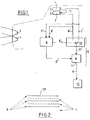
- the two cameras 1, 2 are associated with a frame separator 6, also appearing in FIG. 1.
- This separator 6 is responsible for selecting the even lines 7 of the video image captured by the first camera 1 , and the odd lines 8 of the video image captured by the second camera 2. All of the lines 7, 8 selected by the frame separator 6 are transmitted to a synchronous mixer 9, capable of providing in real time a composite image of the roadway, composed of the odd lines 8 received in the ultraviolet , alternated with even lines 7 received in the near infrared.
- This reconstituted video image will be available to the driver, either on a video monitor 12 integrated into his dashboard, or using a head-up display system revealing it on the windshield.
- FIG. 1 there is also shown schematically the first projector 3 lighting the roadway with infrared rays, and the second projector 4 lighting the roadway with ultraviolet rays, as well as the synchronization circuit 5 of the cameras 1 and 2.
- the synchronous mixer 9 comprises on the one hand a switch 10 directly receiving the two video signals 7 ′, 8 ′ coming respectively from the first and from the second camera, as well as a control signal 6 ′ coming from the frame separator 6 and other share a summator 11 ensuring the summation of common synchronization signals 6 ⁇ coming from the frame separator 6 and the signal 10 ′ delivered by the switch 10.
- the final signal 9 ′ emitted by the mixer 9 is a composite video signal which is then transmitted to a monitor 12 of CRT type ("Cathode Ray Tube", or in French CRT screen) or of LCD type ("liquid crystal device” "), or a HUD (Head Up Display) projection system.
- CRT type Cathode Ray Tube
- LCD type liquid crystal device
- HUD Head Up Display
- the device of the invention provides the display of all the lines of a complete image at the video-television rate.
- FIG. 2 schematically illustrates the formation of a composite image, formed simultaneously in the ultraviolet and infrared spectra.
- CCIR International Consultative Committee for Radio-communication
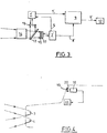
- FIG. 3 relates to a second embodiment of the invention, according to which an infrared and ultraviolet separating plate 13 is used, disposed at the output of an image reception objective 14.
- the shooting is ensured by two video sensors 16, 17 of respective technologies CID and CCD or by two sensors "CCD thinned", sensitive both in the ultraviolet spectrum and in the near infrared.
- These two sensors 16, 17, the objective 14 and the separating blade 13 will advantageously be grouped in a camera assembly which is not highlighted in this diagram for reasons of clarity.
- the separating plate 13 can for example ensure total reflection in the band 0.3 - 0.4 ⁇ m, in the direction of the first sensor 16, and transmit the spectral band 0.4 ⁇ m - 1.2 ⁇ m to the second sensor 17, by means of a spectral filter 15, (for example of the type marketed under the reference RG 715 of the SCHOTT brand), allowing only wavelengths greater than 0.7 ⁇ to pass.
- This filter facilitates in particular the production of the separating plate which will be transparent at wavelengths between 0.4 ⁇ m and 1.2 ⁇ m, and completely reflective with ultraviolet light.
- This diagram also mentions the presence of the control and processing modules 1 ′ and 2 ′ of the signals coming from the matrix sensors 16 and 17.
- the synchronous mixer 9 recipient of an ultraviolet video signal 7 ′ coming from the first sensor 16, and an infrared video signal 8 ′ coming from the second sensor 17.
- the synchronous mixer delivers a CCIR video signal 9 ′ whose display is ensured by the monitor 12.
- the operation of this device comparable to that of FIG. 1, since the sensors 16 and 17 capture two superimposable images of the road, lit respectively in the ultraviolet and the near infrared.
- a third embodiment of the invention illustrated in FIG. 4, consists in lighting the road using long-range projectors 3, 4, radiating respectively in the near infrared range (0.7 ⁇ m - 1.2 ⁇ m) and ultraviolet (0.3 ⁇ m -0.4 ⁇ m), and to capture an image of the roadway thus lit by means of a single CID camera 18 with a very broad spectral band of sensitivity: 0.2 ⁇ m - 1.2 ⁇ m. All the details reflecting in the near infrared and ultraviolet are selected thanks to the arrangement of the ultraviolet 19 and infrared 20 filters so as to be captured by the single camera 18 and to be sent to a monitor 12 integrated into the dashboard , or projected in head-up vision on the windshield.
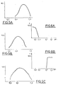
- FIG. 5A shows the sensitivity spectral band of a C.C.D sensor, in FIG. 5B that of a C.I.D sensor, and in FIG. 5C that of a C.I.D sensor. broadband, these three sensors being usable in accordance with the invention.
- the graphs in FIGS. 6 A and 6 B reproduce the transmission curves of ultraviolet and infrared filters usable in accordance with the first variant of the invention.
- the image perceived by the driver includes details captured by ultraviolet lighting, as well as details captured by infrared lighting.
- the process of the invention is relatively simple to implement and the costs promise to be reasonable for improving the night vision obtained.
- the multispectacle image processing techniques implemented in the military and space fields are much heavier to implement, because they require the adaptation of more substantial computer hardware.
Landscapes
- Engineering & Computer Science (AREA)
- Multimedia (AREA)
- Signal Processing (AREA)
- Mechanical Engineering (AREA)
- Closed-Circuit Television Systems (AREA)
- Studio Devices (AREA)
- Traffic Control Systems (AREA)
Applications Claiming Priority (2)
| Application Number | Priority Date | Filing Date | Title |
|---|---|---|---|
| FR9103484 | 1991-03-22 | ||
| FR9103484A FR2674198B1 (fr) | 1991-03-22 | 1991-03-22 | Procede et dispositif d'amelioration de la vision automobile de nuit. |
Publications (1)
| Publication Number | Publication Date |
|---|---|
| EP0505237A1 true EP0505237A1 (de) | 1992-09-23 |
Family
ID=9411013
Family Applications (1)
| Application Number | Title | Priority Date | Filing Date |
|---|---|---|---|
| EP92400627A Withdrawn EP0505237A1 (de) | 1991-03-22 | 1992-03-11 | Verfahren und Einrichtung für Nachtsichtverbesserung in Fahrzeugen |
Country Status (2)
| Country | Link |
|---|---|
| EP (1) | EP0505237A1 (de) |
| FR (1) | FR2674198B1 (de) |
Cited By (20)
| Publication number | Priority date | Publication date | Assignee | Title |
|---|---|---|---|---|
| FR2713165A1 (fr) * | 1993-12-04 | 1995-06-09 | Bosch Gmbh Robert | Dispositif pour régler la distance d'éclairage des phares de véhicules à moteur. |
| FR2726094A1 (fr) * | 1994-10-24 | 1996-04-26 | Valeo Vision | Dispositif de visualisation d'informations dans un vehicule automobile |
| FR2730035A1 (fr) * | 1995-01-30 | 1996-08-02 | Valeo Vision | Projecteur infrarouge pour systeme d'aide a la vision pour vehicule automobile et systeme d'aide a la vision le comportant |
| FR2759043A1 (fr) * | 1997-02-06 | 1998-08-07 | Bosch Gmbh Robert | Installation pour regler la portee des projecteurs d'un vehicule |
| EP1298481A3 (de) * | 2001-09-24 | 2004-01-28 | Hella KG Hueck & Co. | Nachtsichtvorrichtung für Fahrzeuge |
| EP1262795A3 (de) * | 2001-05-31 | 2004-04-14 | DaimlerChrysler AG | Verfahren zur Verbesserung der Sicht in Fahrzeugen |
| WO2004068216A1 (de) * | 2003-01-28 | 2004-08-12 | Carl Zeiss Vision Gmbh | Vorrichtung und verfahren zum anpassen einer position eines brillenglases relativ zur position einer pupille |
| WO2004070449A1 (de) * | 2003-02-06 | 2004-08-19 | Bayerische Motoren Werke Aktiengesellschaft | Verfahren und vorrichtung zur sichtbarmachung der umgebung eines fahrzeugs mit umgebungsabhängiger fusion eines infrarot- und eines visuell-abbilds |
| DE10348117A1 (de) * | 2003-08-20 | 2005-03-17 | Daimlerchrysler Ag | Fahrzeug-Infrarotstrahlungsquelle für ein Infrarot-Nachtsichtsystem |
| EP1553429A1 (de) * | 2004-01-09 | 2005-07-13 | Valeo Vision | System und Verfahren für ein Fahrzeug um die Verkehrsbedingungen zu detektieren |
| EP1386781A3 (de) * | 2002-08-02 | 2006-10-04 | Robert Bosch Gmbh | Vorrichtung zum automatischen Schalten von Beleuchtungseinrichtungen, insbesondere für ein Kraftfahrzeug |
| US7362215B2 (en) | 2000-11-29 | 2008-04-22 | Robert Bosch Gmbh | System and method for monitoring the surroundings of a vehicle |
| US8818042B2 (en) | 2004-04-15 | 2014-08-26 | Magna Electronics Inc. | Driver assistance system for vehicle |
| US8842176B2 (en) | 1996-05-22 | 2014-09-23 | Donnelly Corporation | Automatic vehicle exterior light control |
| US8917169B2 (en) | 1993-02-26 | 2014-12-23 | Magna Electronics Inc. | Vehicular vision system |
| US8993951B2 (en) | 1996-03-25 | 2015-03-31 | Magna Electronics Inc. | Driver assistance system for a vehicle |
| US9171217B2 (en) | 2002-05-03 | 2015-10-27 | Magna Electronics Inc. | Vision system for vehicle |
| US9436880B2 (en) | 1999-08-12 | 2016-09-06 | Magna Electronics Inc. | Vehicle vision system |
| US10071676B2 (en) | 2006-08-11 | 2018-09-11 | Magna Electronics Inc. | Vision system for vehicle |
| DE102006055905B4 (de) * | 2006-11-27 | 2020-01-30 | Adc Automotive Distance Control Systems Gmbh | Verfahren zur Fahrzeugumfelderkennung und Vorrichtung zur Umfelderkennung in einem Kraftfahrzeug |
Families Citing this family (1)
| Publication number | Priority date | Publication date | Assignee | Title |
|---|---|---|---|---|
| DE4304005A1 (de) * | 1993-02-11 | 1994-08-18 | Pranab Dr Sarma | Überwachungsvorrichtung für Fahrzeuge |
Citations (3)
| Publication number | Priority date | Publication date | Assignee | Title |
|---|---|---|---|---|
| US4692798A (en) * | 1984-01-09 | 1987-09-08 | Nissan Motor Company, Limited | Apparatus and process for improving visibility of object within visual field |
| FR2621872A1 (fr) * | 1987-10-20 | 1989-04-21 | Bonino Gerard | Retroviseur video integral a telemetrie optique |
| US4985816A (en) * | 1988-03-28 | 1991-01-15 | Nissan Motor Company, Ltd. | Vehicle headlamp |
-
1991
- 1991-03-22 FR FR9103484A patent/FR2674198B1/fr not_active Expired - Fee Related
-
1992
- 1992-03-11 EP EP92400627A patent/EP0505237A1/de not_active Withdrawn
Patent Citations (3)
| Publication number | Priority date | Publication date | Assignee | Title |
|---|---|---|---|---|
| US4692798A (en) * | 1984-01-09 | 1987-09-08 | Nissan Motor Company, Limited | Apparatus and process for improving visibility of object within visual field |
| FR2621872A1 (fr) * | 1987-10-20 | 1989-04-21 | Bonino Gerard | Retroviseur video integral a telemetrie optique |
| US4985816A (en) * | 1988-03-28 | 1991-01-15 | Nissan Motor Company, Ltd. | Vehicle headlamp |
Cited By (52)
| Publication number | Priority date | Publication date | Assignee | Title |
|---|---|---|---|---|
| US8917169B2 (en) | 1993-02-26 | 2014-12-23 | Magna Electronics Inc. | Vehicular vision system |
| FR2713165A1 (fr) * | 1993-12-04 | 1995-06-09 | Bosch Gmbh Robert | Dispositif pour régler la distance d'éclairage des phares de véhicules à moteur. |
| FR2726094A1 (fr) * | 1994-10-24 | 1996-04-26 | Valeo Vision | Dispositif de visualisation d'informations dans un vehicule automobile |
| FR2730035A1 (fr) * | 1995-01-30 | 1996-08-02 | Valeo Vision | Projecteur infrarouge pour systeme d'aide a la vision pour vehicule automobile et systeme d'aide a la vision le comportant |
| US8993951B2 (en) | 1996-03-25 | 2015-03-31 | Magna Electronics Inc. | Driver assistance system for a vehicle |
| US8842176B2 (en) | 1996-05-22 | 2014-09-23 | Donnelly Corporation | Automatic vehicle exterior light control |
| FR2759043A1 (fr) * | 1997-02-06 | 1998-08-07 | Bosch Gmbh Robert | Installation pour regler la portee des projecteurs d'un vehicule |
| US6144159A (en) * | 1997-02-06 | 2000-11-07 | Robert Bosch Gmbh | Apparatus for regulating the illumination field of a vehicle headlight |
| US9436880B2 (en) | 1999-08-12 | 2016-09-06 | Magna Electronics Inc. | Vehicle vision system |
| US7362215B2 (en) | 2000-11-29 | 2008-04-22 | Robert Bosch Gmbh | System and method for monitoring the surroundings of a vehicle |
| EP1262795A3 (de) * | 2001-05-31 | 2004-04-14 | DaimlerChrysler AG | Verfahren zur Verbesserung der Sicht in Fahrzeugen |
| EP1298481A3 (de) * | 2001-09-24 | 2004-01-28 | Hella KG Hueck & Co. | Nachtsichtvorrichtung für Fahrzeuge |
| US10351135B2 (en) | 2002-05-03 | 2019-07-16 | Magna Electronics Inc. | Vehicular control system using cameras and radar sensor |
| US9834216B2 (en) | 2002-05-03 | 2017-12-05 | Magna Electronics Inc. | Vehicular control system using cameras and radar sensor |
| US9643605B2 (en) | 2002-05-03 | 2017-05-09 | Magna Electronics Inc. | Vision system for vehicle |
| US10118618B2 (en) | 2002-05-03 | 2018-11-06 | Magna Electronics Inc. | Vehicular control system using cameras and radar sensor |
| US9555803B2 (en) | 2002-05-03 | 2017-01-31 | Magna Electronics Inc. | Driver assistance system for vehicle |
| US9171217B2 (en) | 2002-05-03 | 2015-10-27 | Magna Electronics Inc. | Vision system for vehicle |
| US10683008B2 (en) | 2002-05-03 | 2020-06-16 | Magna Electronics Inc. | Vehicular driving assist system using forward-viewing camera |
| US11203340B2 (en) | 2002-05-03 | 2021-12-21 | Magna Electronics Inc. | Vehicular vision system using side-viewing camera |
| EP1386781A3 (de) * | 2002-08-02 | 2006-10-04 | Robert Bosch Gmbh | Vorrichtung zum automatischen Schalten von Beleuchtungseinrichtungen, insbesondere für ein Kraftfahrzeug |
| WO2004068216A1 (de) * | 2003-01-28 | 2004-08-12 | Carl Zeiss Vision Gmbh | Vorrichtung und verfahren zum anpassen einer position eines brillenglases relativ zur position einer pupille |
| US7199366B2 (en) | 2003-02-06 | 2007-04-03 | Bayerische Moteren Werke Aktiengesellschaft | Method and device for visualizing a motor vehicle environment with environment-dependent fusion of an infrared image and a visual image |
| WO2004070449A1 (de) * | 2003-02-06 | 2004-08-19 | Bayerische Motoren Werke Aktiengesellschaft | Verfahren und vorrichtung zur sichtbarmachung der umgebung eines fahrzeugs mit umgebungsabhängiger fusion eines infrarot- und eines visuell-abbilds |
| CN100401129C (zh) * | 2003-02-06 | 2008-07-09 | 宝马股份公司 | 用于以红外图像和可见图像与环境相关的结合来显示车辆环境的方法和装置 |
| DE10348117B4 (de) * | 2003-08-20 | 2005-08-25 | Daimlerchrysler Ag | Fahrzeug-Infrarotstrahlungsquelle für ein Infrarot-Nachtsichtsystem |
| DE10348117A1 (de) * | 2003-08-20 | 2005-03-17 | Daimlerchrysler Ag | Fahrzeug-Infrarotstrahlungsquelle für ein Infrarot-Nachtsichtsystem |
| EP1553429A1 (de) * | 2004-01-09 | 2005-07-13 | Valeo Vision | System und Verfahren für ein Fahrzeug um die Verkehrsbedingungen zu detektieren |
| FR2864932A1 (fr) * | 2004-01-09 | 2005-07-15 | Valeo Vision | Systeme et procede de detection de conditions de circulation pour vehicule automobile |
| US7350945B2 (en) | 2004-01-09 | 2008-04-01 | Valeo Vision | System and method of detecting driving conditions for a motor vehicle |
| US10187615B1 (en) | 2004-04-15 | 2019-01-22 | Magna Electronics Inc. | Vehicular control system |
| US9191634B2 (en) | 2004-04-15 | 2015-11-17 | Magna Electronics Inc. | Vision system for vehicle |
| US9948904B2 (en) | 2004-04-15 | 2018-04-17 | Magna Electronics Inc. | Vision system for vehicle |
| US10015452B1 (en) | 2004-04-15 | 2018-07-03 | Magna Electronics Inc. | Vehicular control system |
| US11847836B2 (en) | 2004-04-15 | 2023-12-19 | Magna Electronics Inc. | Vehicular control system with road curvature determination |
| US10110860B1 (en) | 2004-04-15 | 2018-10-23 | Magna Electronics Inc. | Vehicular control system |
| US9609289B2 (en) | 2004-04-15 | 2017-03-28 | Magna Electronics Inc. | Vision system for vehicle |
| US9008369B2 (en) | 2004-04-15 | 2015-04-14 | Magna Electronics Inc. | Vision system for vehicle |
| US10306190B1 (en) | 2004-04-15 | 2019-05-28 | Magna Electronics Inc. | Vehicular control system |
| US8818042B2 (en) | 2004-04-15 | 2014-08-26 | Magna Electronics Inc. | Driver assistance system for vehicle |
| US10462426B2 (en) | 2004-04-15 | 2019-10-29 | Magna Electronics Inc. | Vehicular control system |
| US11503253B2 (en) | 2004-04-15 | 2022-11-15 | Magna Electronics Inc. | Vehicular control system with traffic lane detection |
| US9428192B2 (en) | 2004-04-15 | 2016-08-30 | Magna Electronics Inc. | Vision system for vehicle |
| US10735695B2 (en) | 2004-04-15 | 2020-08-04 | Magna Electronics Inc. | Vehicular control system with traffic lane detection |
| US9736435B2 (en) | 2004-04-15 | 2017-08-15 | Magna Electronics Inc. | Vision system for vehicle |
| US11148583B2 (en) | 2006-08-11 | 2021-10-19 | Magna Electronics Inc. | Vehicular forward viewing image capture system |
| US10787116B2 (en) | 2006-08-11 | 2020-09-29 | Magna Electronics Inc. | Adaptive forward lighting system for vehicle comprising a control that adjusts the headlamp beam in response to processing of image data captured by a camera |
| US11396257B2 (en) | 2006-08-11 | 2022-07-26 | Magna Electronics Inc. | Vehicular forward viewing image capture system |
| US11623559B2 (en) | 2006-08-11 | 2023-04-11 | Magna Electronics Inc. | Vehicular forward viewing image capture system |
| US10071676B2 (en) | 2006-08-11 | 2018-09-11 | Magna Electronics Inc. | Vision system for vehicle |
| US11951900B2 (en) | 2006-08-11 | 2024-04-09 | Magna Electronics Inc. | Vehicular forward viewing image capture system |
| DE102006055905B4 (de) * | 2006-11-27 | 2020-01-30 | Adc Automotive Distance Control Systems Gmbh | Verfahren zur Fahrzeugumfelderkennung und Vorrichtung zur Umfelderkennung in einem Kraftfahrzeug |
Also Published As
| Publication number | Publication date |
|---|---|
| FR2674198B1 (fr) | 1993-05-28 |
| FR2674198A1 (fr) | 1992-09-25 |
Similar Documents
| Publication | Publication Date | Title |
|---|---|---|
| EP0505237A1 (de) | Verfahren und Einrichtung für Nachtsichtverbesserung in Fahrzeugen | |
| EP0830267B2 (de) | Fahrzeug-rückblicksystem mit panoramischer sicht | |
| US9131120B2 (en) | Multi-camera vision system for a vehicle | |
| US6498620B2 (en) | Vision system for a vehicle including an image capture device and a display system having a long focal length | |
| EP1553429B1 (de) | System und Verfahren für ein Fahrzeug um die Verkehrsbedingungen zu detektieren | |
| US10390004B2 (en) | Stereo gated imaging system and method | |
| CN104076514B (zh) | 一种汽车信息显示方法及装置 | |
| US20030155513A1 (en) | Active night vision system for vehicles employing short-pulse laser illumination and a gated camera for image capture | |
| FR2903199A1 (fr) | Systeme optique pour projecteur et projecteur correspondant | |
| JP2003203294A (ja) | 車両での視界を改善する方法 | |
| JP2005229317A (ja) | 画像表示システム及び撮像装置 | |
| EP0359634B1 (de) | Periskop zum Tag- und Nachtbetrieb für Panzerfahrzeuge | |
| WO2008142270A2 (fr) | Procédé et dispositif à deux lasers pour la détection de systèmes optiques grossissants | |
| US20130083195A1 (en) | Polarization-based anti-blinding night vision system, vehicle comprising same, and method therefor | |
| RU2191417C1 (ru) | Оптико-электронный прибор для дистанционного обнаружения систем скрытого видеонаблюдения | |
| FR3061461A1 (fr) | Systeme d'avertissement lumineux pour vehicule automobile et procede d'avertissement lumineux | |
| CN2606694Y (zh) | 车载夜视辅助装置 | |
| FR2736731A1 (fr) | Dispositif de detection d'organes optiques pointes sur le dispositif | |
| JP2002290788A (ja) | 車載撮像装置 | |
| FR3087986A1 (fr) | Dispositif d’affichage avec superposition d’image autostereoscopique sur une image reelle | |
| FR2736491A1 (fr) | Dispositif de detection optique | |
| KR20040079450A (ko) | 감시카메라의 역광차단장치 | |
| BE558598A (de) | ||
| JPS60145782A (ja) | 視界向上装置 | |
| CN105898193A (zh) | 一种基于偏振光谱的雾天影像增强系统 |
Legal Events
| Date | Code | Title | Description |
|---|---|---|---|
| PUAI | Public reference made under article 153(3) epc to a published international application that has entered the european phase |
Free format text: ORIGINAL CODE: 0009012 |
|
| AK | Designated contracting states |
Kind code of ref document: A1 Designated state(s): DE ES FR GB |
|
| 17P | Request for examination filed |
Effective date: 19930226 |
|
| 17Q | First examination report despatched |
Effective date: 19940617 |
|
| STAA | Information on the status of an ep patent application or granted ep patent |
Free format text: STATUS: THE APPLICATION HAS BEEN WITHDRAWN |
|
| 18W | Application withdrawn |
Withdrawal date: 19941128 |